1. Introduction
In the interior ballistics lumped parameters model, described in STANAG 4367 [
1], the solution of equations describing the interior ballistics cycle starts at the moment when the priming mixture is completely burned, and the burning of the propellant charge starts. The pressure value produced by the action of the primer is called the ‘ignition pressure’. Usually, it is estimated as the value of pressure produced by the full combustion of the priming mixture in the free volume inside the cartridge case. The free volume is defined as the difference between the case capacity and the volume of the propellant charge. The problem is that the values of the force and the covolume for priming mixtures are not available, which is why values determined for black powder are often used; it is believed that its characteristics do not differ much from those of the commonly used priming mixtures. The question is to what extent this belief is justified? Several studies have attempted to experimentally determine the ignition pressure.
The method for experimentally determining the ignition pressure value consists of measuring the maximum pressure value inside a closed chamber, into which the products of the combustion of the priming mixture inflow. The method is based on the assumption that during the action of the primer the propellant charge behaves like an inert substance and starts to burn after the end of the primer action. Thus, when the propellant is replaced by an inert substance one can expect that the measured maximum pressure value is equal to the ignition pressure. The free volume in the chamber is equal to the free volume in a cartridge case; it is attained by using a chamber of a capacity equal to the free volume [
2] or by filling the chamber with an inert granular material [
3,
4].
In [
2], the ignition pressure for 9 mm pistol ammunition was determined. Values from 10–20 MPa were measured. In [
3], six primers used in 5.56 mm ammunition were investigated. The chamber had a capacity of 1.9 cm
3. The pressure was measured by two piezoelectric gauges mounted at the side wall of the chamber. The chamber was filled with steel balls with a diameter of 2.5 mm. The free volume was equal to 0.984 cm
3 (in a cartridge of 0.980 cm
3). The measured maximum pressure values for the empty chamber ranged from 3.5–7.0 MPa. When the chamber was filled with steel balls, the maximum pressure values measured by the gauge closest to the primer ranged from 2.6 to 5.1 MPa, while the values measured by the most distant gauge ranged from 1.9 to 3.8 MPa.
In the report by [
4], the ignition pressure values were determined for the N.41 primer used in 5.56 mm ammunition. A glass chamber of capacity 1.8 cm
3 was used. The pressure was measured at the end of the chamber opposite to the primer. In the case of the empty chamber, the maximum pressure value was equal to 3 MPa and the pressure rise time was 25–35 µs. When the chamber was filled with Teflon balls with a diameter of 0.908 mm, the pressure value increased to 18.3 MPa in 18–20 µs. When the chamber was filled with a propellant, the pressure value increased to 30.2 MPa in 10–12 µs. The higher-pressure value and the shorter rise time were attributed to the ignition and combustion of the propellant. The results obtained in the cartridge simulator were compared with the results of live firing. Based on the results of pressure measurements inside the case, it was determined that there was a very fast pressure rise to 28 MPa in 30 µs and then the pressure value almost stabilised for a time.
In [
5], an attempt was made to calculate the value of the ignition pressure by using the Cheetah thermodynamic code. The calculations were performed for the priming mixture used in primer N. 41, namely: lead styphnate 37%, barium nitrate 32%, antimony sulphide 15%, aluminium powder 7%, tetracene 4%, and PETN 5%; it was assumed that the explosives and aluminium undergo the reaction, while barium nitride and antimony sulphide act as heat sinks when heated to the boiling temperature. The mass of the priming mixture was equal to 25 mg, which corresponds to the loading density of 13.9 kg/m
3 in a 1.8 cm
3 capacity chamber. The calculated ignition pressure value was equal to 7.4 MPa; this value is much higher than the 3.0 MPa measured in [
4].
In the cited works, two methods of adjusting the free volume in the experimental setups to the free volume in the ammunition case were used, namely restricting the sizes of the chamber and filling the chamber with an inert, granular substance. In this work the two methods were compared in one experimental setup; moreover, two sizes of the grains of the inert filling were used. The aim of this was to check, how the form of the chamber filling influences measured values of the ignition pressure. Similar to the work by [
3] and [
4], pressure values were measured inside a closed chamber of a capacity equal to the capacity of the cartridge case, filled with inert substances. The second aim of the presented investigations was a comparison of the values of the ignition pressure determined in the model experiments and measured inside the case at the live firings. The results obtained are used to discuss the problem of choosing the ignition pressure value in interior ballistics modelling.
The aim of this work is to estimate the ignition pressure value produced by a primer used in 12.7 × 99 mm ammunition with an M33 Ball projectile, produced by MESKO SA (Skarżysko-Kamienna, Poland). Similar to the work by [
3,
4], pressure values were measured inside a closed chamber of a capacity equal to the capacity of the cartridge case, filled with inert substances. The ignition pressure values determined in the chamber were compared with the results of measurements of the pressure value inside the cartridge case at the live firings. The results obtained are used to discuss the problem of choosing the ignition pressure value in interior ballistics modelling.
2. Materials and Methods
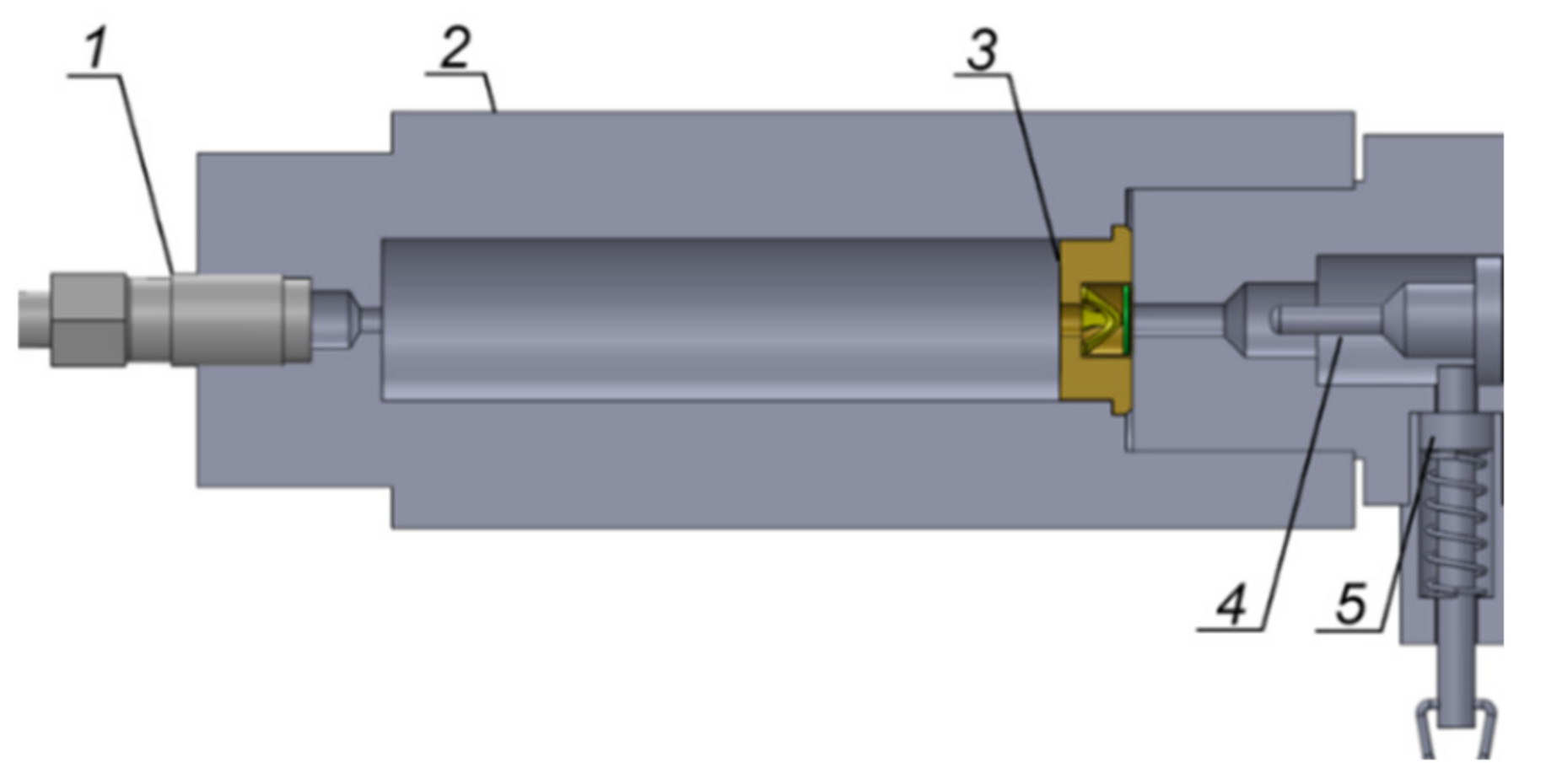
The experimental setup used is shown schematically in
Figure 1.
The chamber had a capacity of 17.5 cm
3, equal to the capacity of the cartridge case of 12.7 × 99 mm ammunition with an M33 Ball projectile, produced by MESKO SA (the volume of the projectile bottom was taken into account). The dimensions of the chamber are presented in
Figure 2.
The bottom of the case with the primer was positioned in the chamber. The chamber was filled with: (1) a sleeve with a 10 mm inner diameter and 64 mm length, and (2) glass balls with diameters of 2 or 4 mm. The sleeve was positioned inside the chamber at the primer side. The sleeve and the balls limited the chamber volume to a free volume of 7.53 cm
3. The size of the glass balls was compared with the size of the propellant NC1214 grains in
Figure 3.
Based on five measurements, the mass of the priming mixture was determined to be 122 ± 10 mg. In addition, the mass of 19 primers was weighted before and after the firings. The difference was 88 ± 5 mg; this is the mass of the priming mixture combustion products that entered the chamber. In accordance with the information obtained from the ammunition producer, the priming mixture contains: lead azide, lead sulphate, tetracene, barium nitride and antimony sulphide. The proportions of the ingredients are unknown.
For each chamber filling, the firings were repeated five times.
The pressure inside the cartridge case at the live firings was measured using the setup shown in
Figure 4. The pressure gauge was positioned 16.8 mm from the case bottom. The pressure courses were synchronised with the moment that the pin impacted onto the primer, by a short-circuit gauge positioned between the pin and the primer.
3. Results and Discussion
The experimental pressure courses were filtered by a 20 kHz low-pass filter and smoothed by the Loess method [
6]. A comparison of the filtered and the smoothed pressure courses is presented in
Figure 5. Pressure courses for various fillings of the chamber are shown in
Figure 6,
Figure 7,
Figure 8 and
Figure 9.
The average maximum pressure value for the empty chamber is equal to 3.3 ± 0.3 MPa; this value is close to the value of 3 MPa obtained for the empty chamber in [
4] but it is lower than the value of 4.2 ± 0.4 MPa, obtained in [
3].
Averaged pressure courses for the three chamber fillings are presented in
Figure 10. Because the free volume for each filling is the same, the maximum pressure values can be used to estimate the ignition pressure value. Three different estimations were obtained: 5.1 ± 0.9 MPa, 2.2 ± 0.4 MPa, 0.7 ± 0.1 MPa. The first value may have been influenced by some dynamic effects caused by the motion of gases. The second and the third values were affected by the heat exchange between the gases and the glass spheres. The total area of the surfaces of 2 mm spheres is 2.25 times greater than the surface area of 2 mm spheres. The rise time is approximately 3 times longer for 2 mm spheres. Thus, the heat losses before attaining the maximum pressure value are approximately 7 times larger for the bed of smaller spheres and this explains the difference between the maximum pressure values. The thermal conductivity value of propellants is 3.0–3.5 times lower than the thermal conductivity of glass; it is assumed that the ignition pressure in the propellant bed is closer to the value determined for 4 mm spheres.
The effect of the inert filling is qualitatively different from that observed in [
4]. The use of the Teflon filling in [
4] caused an increase in the pressure value from 3.0 to 18.3 MPa. Teflon had a thermal conductivity value close to the value for propellants (0.2 W/(mK) [
7]). The higher thermal conductivity value of glass may be one of the reasons why the maximum pressure values in tests with glass fillings were lower than those measured for the empty chamber, in our experiments. The difference in the space scale may be another reason; it is 2.3 times higher for a 12.7 mm gun than for a 5.56 mm gun. The processes of thermal conductivity scale with the square of linear dimensions. Thus, the effects of heat loss are more pronounced in the 12.7 mm gun.
Let us compare the estimated ignition pressure values with the assessment based on the black powder data determined in [
8]. (The force 298 kJ/kg and the covolume 0.5 dm
3/kg). By assuming the mass of the priming mixture of 88 mg and the free volume 7.35 cm
3, we can assess the loading density as being equal to 12 kg/m
3. The calculated value of the ignition pressure is equal to 3.57 MPa; this value situates itself between the lowest and the highest estimates of the ignition pressure and suggests that, by using the black powder data, a rough estimation of the ignition pressure value can be made.
The initial parts of the pressure courses recorded in seven live firing tests are presented in
Figure 11; they are characterised by a fast increase in pressure value at approximately 100 ∝s, which is followed by a relative stabilisation of the pressure value. The same characteristics of the pressure courses were observed in [
4]. The differences concern the rise time scale (100 versus 30 ∝s) and the pressure value (from 13 to 20 MPa versus 28 MPa).
If we assume that the pressure values at the end of the fast rise period correspond to the ignition pressure, we come to values one order of magnitude higher than those determined in the experiments with the inert filling; this may prove that the method of experimental estimation of the ignition pressure value based on the chambers with inert filling is methodologically incorrect; however, another possibility can be discussed.
In [
4], it was observed that the filling of the case simulator by a propellant produced higher pressures than the use of inert filling; this effect explains that the propellant is ignited and starts to burn in a very short time; it means that the height of the pressure rise is an effect of the superposition of the pressure produced by the primer and the pressure produced by the combustion of a small amount of the propellant. For a rough estimation of the amount of the propellant burnt, we can refer to the results in [
9], where a method of identification of the experimental shape function was presented. Using this function takes into account the prolonged ignition process in lumped parameters interior ballistics models. Results of the analysis presented in [
9] suggest that, during the action of the primer in a 12.7 mm gun, approximately 2% of the propellant is burned. Assuming that the ignition pressure value is 2.5 MPa and assuming the values of the force and covolume determined for NC1214 propellant, we can estimate that combustion of 2% of the propellant charge produces a pressure value equal to 23 MPa; this value is of the same order of magnitude as that measured in the live firing tests.
The question arises: is it possible that the propellant was ignited in 100 ∝s and a part of it was burnt? In [
10], it was found that 90 ∝s lasts from the time instant when the primer gases reach the propellant bed to the ignition of the propellant; however, in the experiment described in [
10], the propellant bed was situated at a distance from the primer outlet. When the propellant bed is situated close to the outlet, the situation is different. The priming mixture of combustion products is accelerated inside the vent of the primer. Thus, they flow around the propellant grains at a very high velocity; it was shown in [
11] that the ignition time shortens with the increase of the Reynolds number of the flow of gases around a propellant grain; this means that the conditions in the neighbourhood of the primer output facilitate fast ignition. The high velocity of gas flow around the propellant grains may cause erosive burning, which accelerates the consumption of the propellant; it should also be taken into account that the braking of the flow penetrating the propellant bed produces high-intensity shocks that increase the pressure and the temperature values; it locally accelerates the ignition and the combustion of the propellant. We can refer to the results of the report by [
12], based on the optical recording of the motion of a projectile inside a truncated barrel; it was deduced that, in the first 50 ∝s, the projectile moves with a high acceleration; this was explained as an effect of the high-pressure value at the outlet of the primer; this pressure is transferred by intergranular stresses onto the projectile and the projectile is initially driven by the thrust of the propellant bed. The estimated maximum pressure value was 117 MPa. Such a high value of pressure can accelerate the process of propellant combustion.
When the gases penetrate the propellant bed their velocity diminishes. The pressure value at the output of the primer also drops and the process of ignition slows down; this process is well illustrated by the results in [
13], in which the ignition time of a thin layer of a propellant, bounded from both sides by inert material inside the cartridge case, was measured. By increasing the distance between the propellant layer and the primer, the ignition time increased exponentially. Thus, the pressure courses shown in
Figure 11 can be interpreted in the following way: in a time shorter than 100 ∝s, the propellant positioned near the outlet of the primer is ignited and, due to erosive burning and high-pressure values, it burns very fast. The decrease in pressure value and flow velocity slows down the process of ignition and burning. In this phase, the energy delivered by the igniter and the burning propellant only compensates for the heat losses to the propellant grains which were not ignited. That is why the pressure value is stabilised. The increasing degree of ignition of the propellant bed gives a net amount of energy and the pressure value starts to rise.
In light of the above interpretation, a question arises: what value of ignition pressure should be chosen in the interior ballistics calculations? One possible answer to this question is illustrated by the plots shown in
Figure 12; they represent the results of pressure measurements in seven live firing tests and interior ballistics calculations, using the model used in [
9]. For the convenience of comparison, the plots were synchronised with respect to the time of attaining the maximum pressure value. In the theoretical calculation, the ignition pressure of 2.5 MPa was assumed. The experimental and calculated pressure courses converge at 1.22 ms. In accordance with the results of the calculations, the projectile attained its velocity of 45 m/s and travelled a distance of 5.5 mm to this moment. The real pressure values were lower than calculated for
t < 1.22 ms. Thus, the real velocity value and the projectile displacement are lower than calculated and this means that the convergence of calculated and measured pressure values takes place shortly after the start of the projectile motion.
The divergence between calculated and measured pressure values takes place in the phase of the process, which is insignificant, from the point of view of assessing the force driving the automatic system of the gun. Determination of this force was the motivation for developing modifications of the lumped parameters interior ballistics model described in [
9]. Thus, taking into account this application of the interior ballistics model, choosing the ignition pressure value determined in the experiments with the inert filling of the chamber is an acceptable approximation; moreover, using the ignition pressure value calculated by the use of black powder data is also acceptable; this value is of the same order of magnitude as the values determined in this work, as well as in [
3] and [
4].
Our results suggest possible directions for the modification of the lumped parameters interior ballistics models [
14]. The initial conditions for solving the interior ballistics equations can be chosen to correspond to the moment at the end of the fast pressure rise, which can be identified in the pressure courses shown in
Figure 11. Approximate estimations suggest that 1–2% of the propellant charge is burnt to this moment. Thus, the pressure value can be calculated as a result of the combustion of this amount of the propellant and the combustion of the priming mixture. The scatter of the pressure plots shown in
Figure 11 proves that the estimation of the pressure value does not need to be very precise; however, the incorporation of this method of determining the initial pressure value needs to make some additional modifications in the lumped parameters model. Such processes as absorption of the heat by propellant grains which were not ignited and returning it after the ignition, as well as the accelerated burning of the heated propellant layers, should be taken into account. Some of these processes are taken into account in multiphase interior ballistics models, originating from the early works of Kuo and Koo [
15] and Gough and Zwarts [
16]; however, incorporating these processes into the lumped parameters models is a challenge.

