
FBM-CSoC Control and Management System for Multi-Port Converter Applied in Hybrid Energy Storage System Used in Microgrid

 , , , , , and
Abstract
:1. Introduction
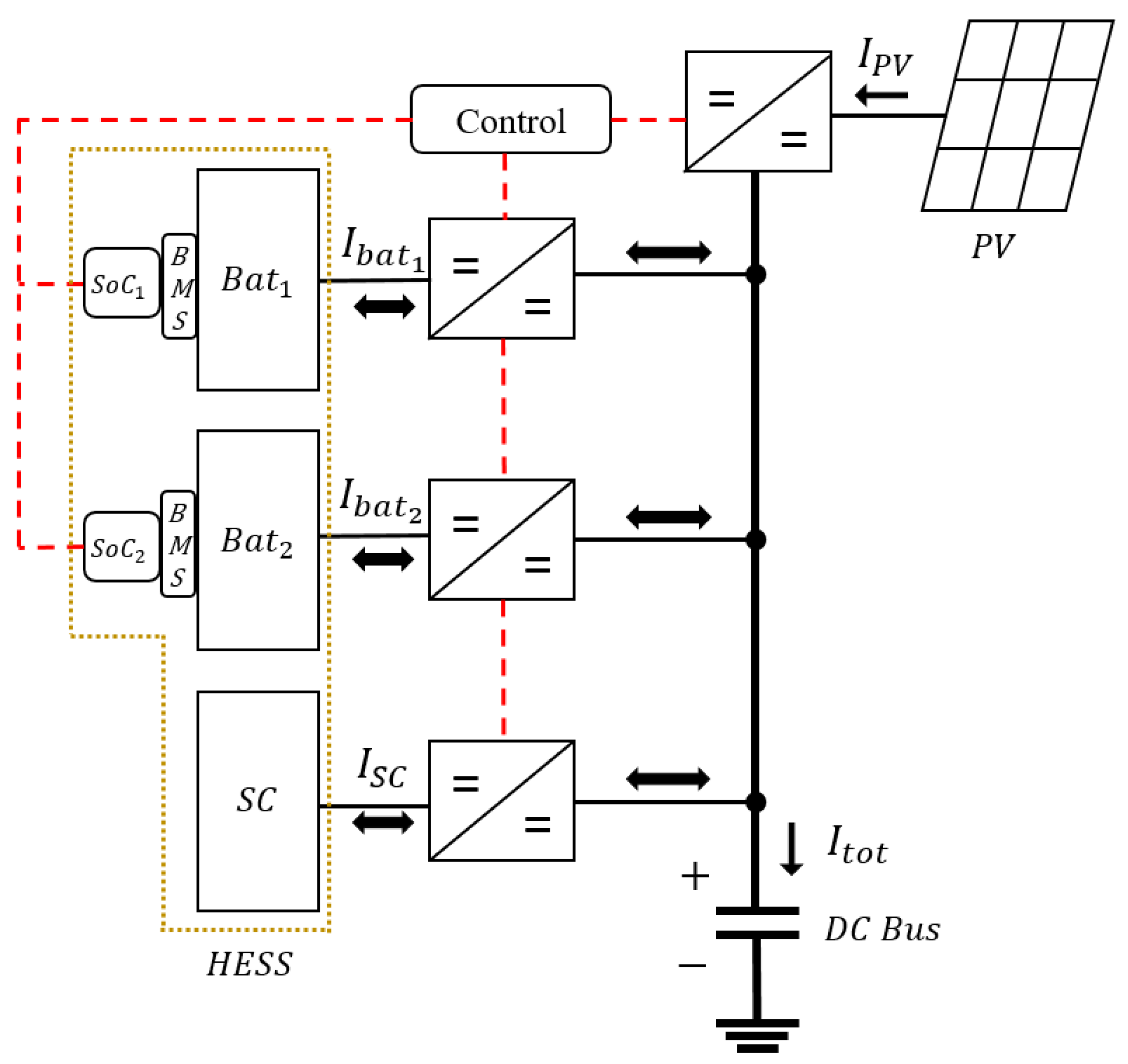
2. MG Topology
2.1. HESS Charging Process in MG
2.2. HESS Discharging Process in MG
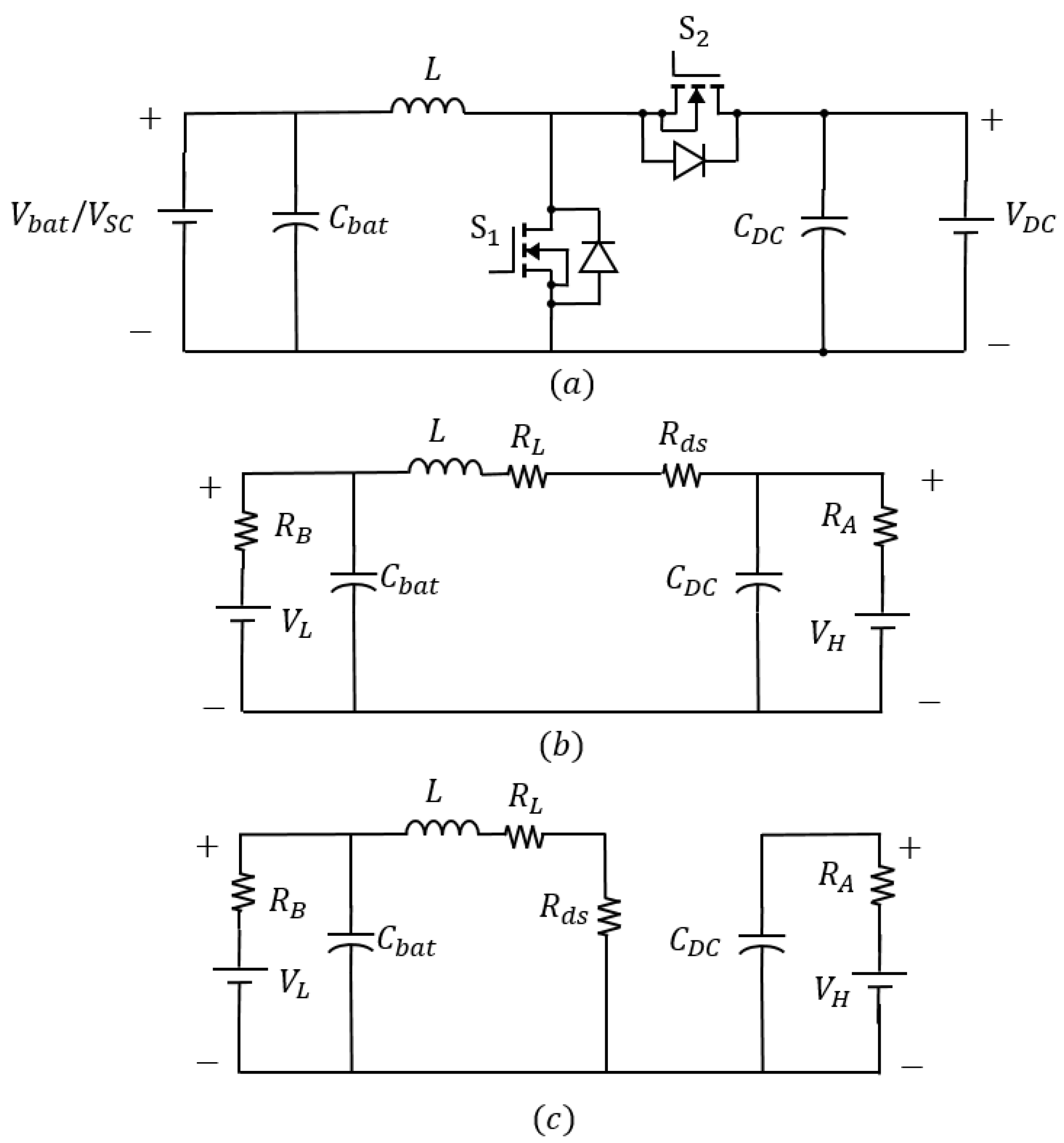
3. Control System Modelling
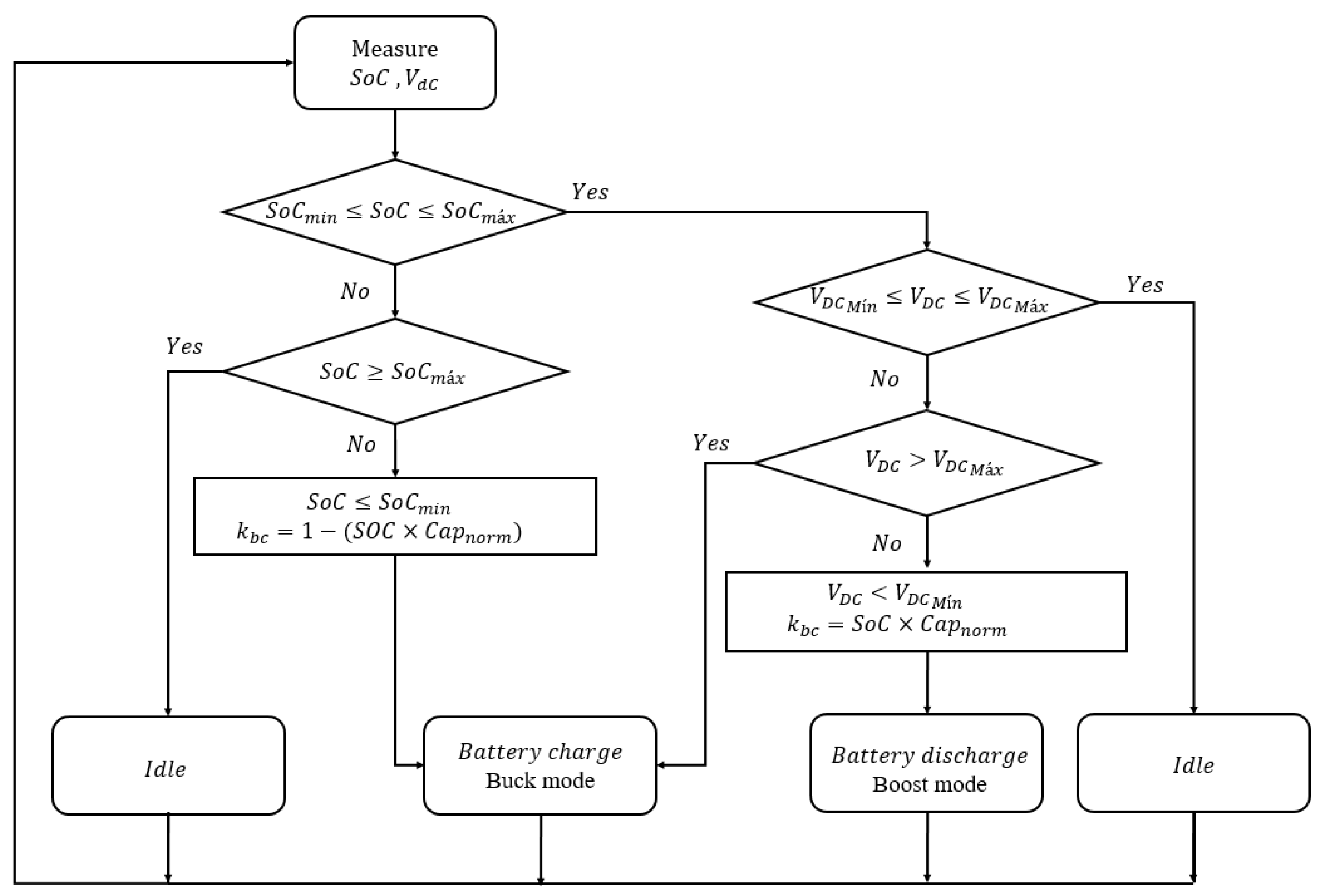
4. Control Logic for HESS Energy Management
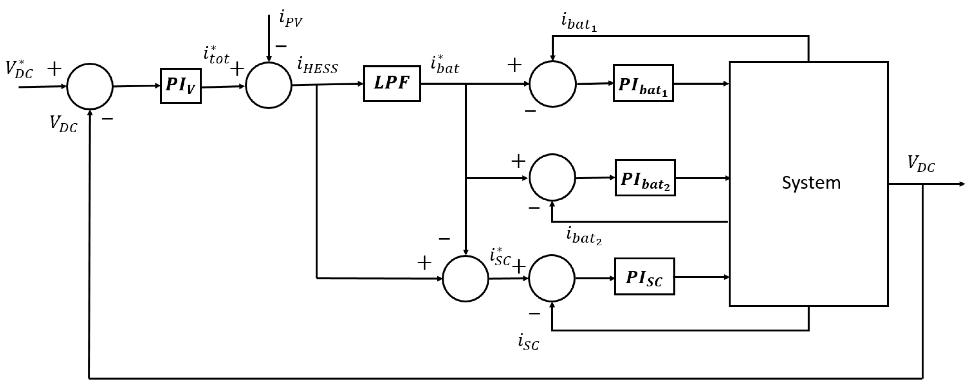
4.1. Conventional Filter-Based Method Structure
4.2. FBM-CSoC Proposed Control Structure
5. Simulation Results and Discussion
5.1. FBM Results
5.2. FBM-CSoC Results
6. Conclusions
Author Contributions
Funding
Institutional Review Board Statement
Informed Consent Statement
Data Availability Statement
Acknowledgments
Conflicts of Interest
Abbreviations
| AC | Alternating Curent |
| BMS | Battery Management System |
| DC | Direct Current |
| DER | Distributed Energy Resources |
| DoD | Depth of Discharge |
| FBM | Filter-Based Method |
| FBM-CSoc | Adapted Filter-Based Method |
| HESS | Hybrid Energy Storage System |
| LPF | Low Pass Filter |
| MGs | Microgrids |
| MPP | Maximum Power Point |
| MPPT | Maximum Power Point Track |
| PI | Proportional Integral |
| PV | Photovoltaic |
| SC | Supercapacitors |
| SoC | State-of-Charge |
| SoH | State-of-Health |
References
- He, L.; Wei, Z.; Yan, H.; Xv, K.-Y.; Zhao, M.-Y.; Cheng, S. A Day-ahead Scheduling Optimization Model of Multi-Microgrid Considering Interactive Power Control. In Proceedings of the 2019 4th International Conference on Intelligent Green Building and Smart Grid (IGBSG), Yi-chang, China, 6–9 September 2019; pp. 666–669. [Google Scholar]
- Smil, V. The long slow rise of solar and wind. Sci. Am. 2014, 310, 52–57. [Google Scholar] [CrossRef] [PubMed]
- Lasseter, R.; Akhil, A.; Marnay, C.; Stephens, J.; Dagle, J.; Guttromson, R.; Meliopoulous, A.; Yinger, R.; Eto, J. The CERTS microgrid concept. In White Paper for Transmission Reliability Program; Office of Power Technologies, US Department of Energy: Washington, DC, USA, 2002; Volume 2, p. 30. [Google Scholar]
- Georgious, R.; Garcia, J.; Garcia, P.; Navarro-Rodriguez, A. A Comparison of Non-Isolated High-Gain Three-Port Converters for Hybrid Energy Storage Systems. Energies 2018, 11, 658. [Google Scholar] [CrossRef]
- Teston, S.; Vilerá, K.; Mezaroba, M.; Rech, C. Control System Development for the Three-Ports ANPC Converter. Energies 2020, 13, 3967. [Google Scholar] [CrossRef]
- Aljarajreh, H.; Lu, D.; Siwakoti, Y.; Tse, C.; See, K. Synthesis and Analysis of Three-Port DC/DC Converters with Two Bidirectional Ports Based on Power Flow Graph Technique. Energies 2021, 14, 5751. [Google Scholar] [CrossRef]
- Haruni, A.; Negnevitsky, M.; Haque, M.; Gargoom, A. A novel operation and control strategy for a standalone hybrid renewable power system. IEEE Trans. Sustain. Energy 2012, 4, 402–413. [Google Scholar] [CrossRef]
- Etxeberria, A.; Vechiu, I.; Camblong, H.; Vinassa, J. Comparison of three topologies and controls of a hybrid energy storage system for microgrids. Energy Convers. Manag. 2012, 54, 113–121. [Google Scholar] [CrossRef]
- Zeng, J.; Ning, J.; Du, X.; Kim, T.; Yang, Z.; Winstead, V. A Four-Port DC–DC Converter for a Standalone Wind and Solar Energy System. IEEE Trans. Ind. Appl. 2019, 56, 446–454. [Google Scholar] [CrossRef]
- Prabhakaran, P.; Agarwal, V. Novel four-port DC–DC converter for interfacing solar PV–fuel cell hybrid sources with low-voltage bipolar DC microgrids. IEEE J. Emerg. Sel. Top. Power Electron. 2018, 8, 1330–1340. [Google Scholar] [CrossRef]
- Tian, Q.; Zhou, G.; Leng, M.; Xu, G.; Fan, X. A nonisolated symmetric bipolar output four-port converter interfacing PV-battery system. IEEE Trans. Power Electron. 2020, 35, 11731–11744. [Google Scholar] [CrossRef]
- Zhao, C.; Round, S.; Kolar, J. An isolated three-port bidirectional DC-DC converter with decoupled power flow management. IEEE Trans. Power Electron. 2008, 23, 2443–2453. [Google Scholar] [CrossRef]
- Tao, H.; Duarte, J.; Hendrix, M. Three-port triple-half-bridge bidirectional converter with zero-voltage switching. IEEE Trans. Power Electron. 2008, 23, 782–792. [Google Scholar]
- Matsuo, H.; Lin, W.; Kurokawa, F.; Shigemizu, T.; Watanabe, N. Characteristics of the multiple-input DC-DC converter. IEEE Trans. Ind. Electron. 2004, 51, 625–631. [Google Scholar] [CrossRef]
- Jiang, W.; Fahimi, B. Multiport power electronic interface—Concept, modeling, and design. IEEE Trans. Power Electron. 2010, 26, 1890–1900. [Google Scholar] [CrossRef]
- Mendis, N.; Muttaqi, K.; Perera, S. Active power management of a super capacitor-battery hybrid energy storage system for standalone operation of DFIG based wind turbines. In Proceedings of the 2012 IEEE Industry Applications Society Annual Meeting, Las Vegas, NV, USA, 7–11 October 2012; pp. 1–8. [Google Scholar]
- Sathishkumar, R.; Kollimalla, S.; Mishra, M. Dynamic energy management of micro grids using battery super capacitor combined storage. In Proceedings of the 2012 Annual IEEE India Conference (INDICON), Kochi, India, 7–9 December 2012; pp. 1078–1083. [Google Scholar]
- Hredzak, B.; Agelidis, V.; Jang, M. A model predictive control system for a hybrid battery-ultracapacitor power source. IEEE Trans. Power Electron. 2013, 29, 1469–1479. [Google Scholar] [CrossRef]
- Teleke, S.; Baran, M.; Bhattacharya, S.; Huang, A. Optimal control of battery energy storage for wind farm dispatching. IEEE Trans. Energy Convers. 2010, 25, 787–794. [Google Scholar] [CrossRef]
- Zhang, J.; Lai, J.; Yu, W. Bidirectional DC-DC converter modeling and unified controller with digital implementation. In Proceedings of the 2008 Twenty-Third Annual IEEE Applied Power Electronics Conference and Exposition, Austin, TX, USA, 24–28 February 2008; pp. 1747–1753. [Google Scholar]
- Kollimalla, S.; Mishra, M.; Narasamma, N. Design and analysis of novel control strategy for battery and supercapacitor storage system. IEEE Trans. Sustain. Energy 2014, 5, 1137–1144. [Google Scholar] [CrossRef]
- Liu, S.; Liu, X.; Jiang, S.; Zhao, Z.; Wang, N.; Liang, X.; Zhang, M.; Wang, L. Application of an Improved STSMC Method to the Bidirectional DC–DC Converter in Photovoltaic DC Microgrid. Energies 2022, 15, 1636. [Google Scholar]
- Ravada, B.; Tummuru, N.; Ande, B. Photovoltaic-Wind and hybrid energy storage integrated multi-source converter configuration for DC microgrid applications. IEEE Trans. Sustain. Energy 2020, 12, 83–91. [Google Scholar] [CrossRef]
- Zhang, Q.; Wang, L.; Li, G.; Liu, Y. A real-time energy management control strategy for battery and supercapacitor hybrid energy storage systems of pure electric vehicles. J. Energy Storage 2020, 31, 101721. [Google Scholar] [CrossRef]
- Habeeb, S.; Tostado-Véliz, M.; Hasanien, H.; Turky, R.; Meteab, W.; Jurado, F. DC Nanogrids for Integration of Demand Response and Electric Vehicle Charging Infrastructures: Appraisal, Optimal Scheduling and Analysis. Electronics 2021, 10, 2484. [Google Scholar] [CrossRef]
- Ramos, G.; Costa-Castelló, R. Energy Management Strategies for Hybrid Energy Storage Systems Based on Filter Control: Analysis and Comparison. Electronics 2022, 11, 1631. [Google Scholar] [CrossRef]
- Jin, Y.; Xu, J.; Zhou, G.; Mi, C. Small-signal modeling and analysis of improved digital peak current control of boost converter. In Proceedings of the 2009 IEEE 6th International Power Electronics and Motion Control Conference, Wuhan, China, 17–20 May 2009; pp. 326–330. [Google Scholar]
- Catherino, H.A. Complexity in battery systems: Thermal runaway in VRLA batteries. J. Power Sources 2005, 158, 977–986. [Google Scholar] [CrossRef]
- Feng, X.; Ouyang, M.; Liu, X.; Lu, L.; Xia, Y.; He, X. Thermal runaway mechanism of lithium ion battery for electric vehicles: A review. Energy Storage Mater. 2018, 10, 246–267. [Google Scholar] [CrossRef]
- Torabi, F.; Esfahanian, V. Study of Thermal-Runaway in Batteries: II. The Main Sources of Heat Generation in Lead-Acid Batteries. J. Electrochem. Soc. 2012, 160, A223. [Google Scholar] [CrossRef]


| Parameter | Value |
|---|---|
| Bidirectional converter inductance | 2 mH |
| Boost converter inductance MPPT | 3 mH |
| DC Bus capacitance | 440 uF |
| PV filter capacitance | 100 uF |
| Supercapacitor’s capacitance | 58 F |
| Switching frequency | 10 kH |
| and controller gains for batteries and | |
| controller gains for supercapacitor | |
| Boost converter PI controller gains for PV | |
| Capacity | Cap_1 = 36 Ah |
| Capacity | Cap_2 = 10 Ah |
| Initial | 0.8 |
| Initial | 0.5 |
| DC Bus reference voltage | 48 V |
| PV Open circuit voltage | 37.4 V |
| PV short-circuit current | 5.9 A |
| PV MPP voltage | 32 V |
| PV MPP current | 4.8 A |
| PV maximum power | 153.6 W |
Publisher’s Note: MDPI stays neutral with regard to jurisdictional claims in published maps and institutional affiliations. |
© 2022 by the authors. Licensee MDPI, Basel, Switzerland. This article is an open access article distributed under the terms and conditions of the Creative Commons Attribution (CC BY) license (https://creativecommons.org/licenses/by/4.0/).
Share and Cite
Cantane, D.A.; Tavares Junior, A.T.; Isernhagen, E.K.S.; Busti, N.D.; Rospirski, A.; Jahn, T.G.; de Oliveira, F.M. FBM-CSoC Control and Management System for Multi-Port Converter Applied in Hybrid Energy Storage System Used in Microgrid. Energies 2022, 15, 5923. https://doi.org/10.3390/en15165923
Cantane DA, Tavares Junior AT, Isernhagen EKS, Busti ND, Rospirski A, Jahn TG, de Oliveira FM. FBM-CSoC Control and Management System for Multi-Port Converter Applied in Hybrid Energy Storage System Used in Microgrid. Energies. 2022; 15(16):5923. https://doi.org/10.3390/en15165923
Chicago/Turabian StyleCantane, Daniel Augusto, Adalberto Teogenes Tavares Junior, Ediane Karine Scherer Isernhagen, Nathalie Danree Busti, Alexsandra Rospirski, Tales Gottlieb Jahn, and Fernando Marcos de Oliveira. 2022. "FBM-CSoC Control and Management System for Multi-Port Converter Applied in Hybrid Energy Storage System Used in Microgrid" Energies 15, no. 16: 5923. https://doi.org/10.3390/en15165923
APA StyleCantane, D. A., Tavares Junior, A. T., Isernhagen, E. K. S., Busti, N. D., Rospirski, A., Jahn, T. G., & de Oliveira, F. M. (2022). FBM-CSoC Control and Management System for Multi-Port Converter Applied in Hybrid Energy Storage System Used in Microgrid. Energies, 15(16), 5923. https://doi.org/10.3390/en15165923