1. Introduction
The design of proper ventilation schemes, to condition dwelling indoor air, has been identified as a key strategy to reduce the risk of aerial transmission/infection of SARS-CoV-2. According to the Federation of European Heating, Ventilation and Air Conditioning Association, REHVA, these systems may have a complementary role in decreasing disease transmission, in indoor spaces, by increasing air change rates, decreasing air recirculation, and increasing the use of outdoor air [
1]. Furthermore, recommend extending HVAC systems operation times; 2 h before opening and 2 h after closing. The implementation of such actions entails a considerably large increase in energy expenditure, inherently associated with the operation of these indoor conditioning systems; considering that thermal energy is the largest end-use within the sector, amounting to 50% of the global final consumption [
2]. Therefore, alternatives capable of reducing energy consumption, or increasing operational efficiency, should be explored. Moreover, to reduce economic investments, these solutions are to be implemented such as to avoid; (i) heavy modifications to base equipment and (ii) hindering the performance/capabilities of these systems.
1.1. Thermosyphons for Air Conditioning Systems
Wickless heat pipes or thermosyphons have proven to be a particularly suitable alternative to enhance thermal energy transfer [
3]. These are gravity-aided devices that enable passive heat exchange between two spaces at different temperatures [
4].
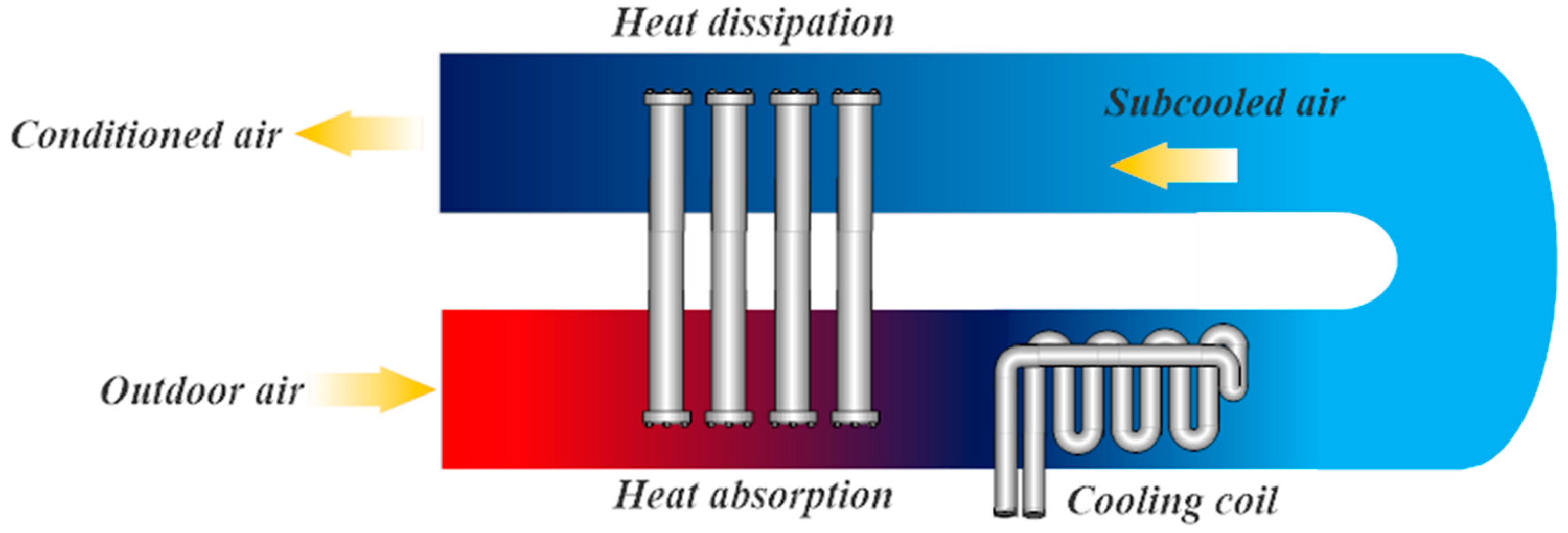
Figure 1 shows the typical implementation of thermosyphons for enhancing air conditioning systems. The thermosyphons absorb heat from the outdoor air through the evaporator at the bottom, reducing the temperature of the inlet air stream and enhancing the dehumidification capacity of the cooling coil; consequently, reducing the energy required to reject the heat of the supply air stream. The heat absorbed by the thermosyphons is then dissipated to the subcooled air stream by the condenser at the outlet duct. The added heat helps reach desired relative humidity, thus eliminating an external source, such as electric heaters [
5]. However, when conditioned air has lower relative humidity, i.e., <30%, an additional process is required; with direct evaporative cooling being the preferred solution.
Several studies regarding the utilization of heat pipes and thermosyphons in conditioning systems are available [
6,
7,
8,
9,
10,
11]. Yau and Ahmadzadehtalatapeh [
12] detail several operation schemes for air conditioning systems in tropical climates employing heat pipes and thermosyphons. The authors conclude that the implementation of these devices, within air conditioning systems, is rather advantageous, since the energy efficiency of the involved processes is increased, in addition, to removing a considerable amount of humidity within the air stream, by cooling it below its dew point temperature. However, they also state that, to achieve this performance enhancement, these devices require a thorough analysis to determine the optimal working fluid of the thermosyphon.
Similarly, Adel et al. [
13] published an experimental and numerical study, testing the performance of thermosyphons in air conditioning systems operation under semi-tropical climates. The performance of the devices was evaluated, ranging the relative humidity from 10 to 100% and the dry-bulb temperatures from 35 to 50 °C, concluding that a 5 to 35% increase in the efficiency of the system could be possible. This represents an overall reduction in energy consumption which, consequently, could even out its distribution disparity, especially, in regions with (i) deficient or inadequate infrastructure, i.e., developing countries, or (ii) with higher energy-intensive requirements, i.e., focused urban hot spots/heat islands and extreme climates.
1.2. Working Fluid Selection and Considerations
To properly build a thermosyphon heat exchanger, several factors should be considered. The accurate designation of operation conditions, i.e., pressure-temperature, as well as inherent design factors, such as working fluid, vessel material, geometry, fluid compatibility, and filling ratio, should be considered [
14,
15,
16,
17,
18].
Working fluid selection depends, mainly, on thermosyphon operation temperature range. This parameter commonly refers to the average vapour temperature inside the evaporator. For air conditioning purposes, the heat exchanger often performs under moderate conditions, i.e., <60 °C, which entails that low temperature working fluids should be preferred [
19].
The influence of the working fluid on thermosyphon performance has been thoroughly studied [
20,
21,
22,
23,
24] involving a variety of substances such as FC-72, R410a, R407C, R134a, distilled water, ethanol, methanol, and acetone, among others. These studies focus on heat pipes/thermosyphon devices as waste-heat recovery or electronic cooling, and most of the authors conclude that refrigerants are most suitable for these applications. However, distilled water and acetone are preferred for setups where operation temperatures range between 35 and 50 °C [
25].
1.3. Aim and Scope
From the aforementioned information, it is clear that, operationally, thermosyphons are a viable option to increase the overall efficiency of air conditioning systems, and, within the requirements imposed by COVID-19 prevention protocols, these remain the most suitable support devices to achieve this. These devices are capable of enhancing the heat transfer capabilities of the system, given their modularity and simplicity, without the additional power consumption and heavy equipment modifications. However, given their, rather, autonomous functional behaviour, an integral analysis should be conducted; involving associated operation variables to develop a broader criterion for working fluid selection. From a design and construction perspective, the filling ratio is a particularly relevant factor, since it directly influences thermosyphon heat transfer capacity, thus constraining its operation range, to a greater extent, compared to the remaining parameters.
This research paper is the first part of an ongoing investigation, regarding the integral design of energy-efficient, thermosyphon-based, low-temperature heat exchangers for indoor air conditioning systems. The proposed configuration is thought of as to be implemented along the southwestern US and northern Mexico border, specifically, the heat islands within the Chihuahuan, Sonoran, and Mojave deserts. These regions are considered to be the hottest and driest places in North America, with average dry bulb temperatures reaching between 38 and 57 °C, and average relative humidity ranging between 16 and 39%.
The psychrometric chart shown in
Figure 2, exemplifies how the coupling, of both these systems, enhances heat transport for air conditioning purposes. The figure outlines the psychrometrics associated with the proposed setup configuration/application; a conventional HVAC system with a thermosyphon heat exchanger that pre-cools (process 1–2) and reheats air (process 3–4), seen in red; a chiller water coil that overcools the air (process 2–3), seen in blue and; direct evaporative cooling (process 4–5), seen in green, as the last stage to ascertain comfort environmental conditions for human occupancy.
Based on this, thermosyphon characterization becomes crucial for heat exchanger design. The experimental evaluation here presented analyses of the effect the combination between working fluid and thermosyphon filling ratio exerts on its performance, in terms of (i) the thermal resistance; (ii) the total heat flow transferred, and (iii) the overall efficiency of the process. For this assessment, one thermosyphon was tested with acetone, distilled water, and ethanol as working fluids at 20, 30, and 40% filling ratios. From compiling experimental data, response surfaces were constructed and used as direct and rough optimization tools. The information provided by this approach is considered to be particularly useful and is introduced for modelling and design purposes.
2. Materials and Methods
A proposed experimental evaluation was performed to ascertain, solely, the thermal behaviour and heat conveyance capabilities of a single thermosyphon, working with different fluids and respective filling ratios. This scheme was deliberately designed as such, to characterize, individually, device performance and eventually determine its replicability in terms of tube bundle heat exchanger design and construction, by implementing the preferred methodology from the available literature. Based on this outline, procedure considerations were:
The main experimental factor is the supplied heat flow at the evaporator since it represents the thermal load the thermosyphon is capable of removing from inlet airflow.
The cooling water flow at the condenser was kept constant, based on the minimum heat flow expected to be dissipated by one thermosyphon.
Ratio between the evaporator and condenser lengths was kept at 2.5 for all treatments.
Working fluid filling ratio was computed as a function of the total internal volume of the vessel, i.e., copper pipe.
2.1. Experimental Setup
The workbench employed is comprised of a copper two-phase closed thermosyphon as shown in
Figure 3.
Copper was chosen as a vessel material due to its malleability, machinability, commercial availability, and long product lifespan. The vessel is a type L copper pipe of 0.5 m in length, 0.0127 m inner diameter, and 0.001 m thickness. Thermosyphon sections are presented in
Figure 3a, and are described as follows: (i) evaporation zone is located in the lower section of the vessel, with a 0.1 m length from the bottom; (ii) adiabatic zone spans 0.15 m above the evaporator and; (iii) the top 0.25 m, are occupied by a water-cooled concentric condenser; fitted using a 0.0254 m diameter pipe with a thickness of 0.00127 m.
The bottom of the vessel is sealed with a copper plug of 0.003 m thickness, whilst the upper end of the thermosyphon is fitted with a needle valve that allows the attachment of a valve array extension to load selected working fluids, as shown in
Figure 3b. Finally, to avoid any heat leakage to the surroundings, the thermosyphon was covered with elastomeric foam with a thickness of 0.0127 m.
The outside of the evaporator was fitted with a Ni-Cr electric resistance heater due to its low temperature-resistivity dependence. The electric resistance has a diameter of 0.0005 m; a rated wattage of 460 W and peak voltage and current of 130 V and 8.6 A. Energy is supplied through a 4.62 kVA rheostat with an output voltage ranging from 0 to 127 V. The available voltage was regulated to deliver 25, 50, 75, 100, and 125 W.
The heat dissipation loop is comprised of a 0.0001 m3/s water pump, and two 0.2 m3 water storage tanks as heat sinks. To measure fluid flow, a Dwyer 641 RM (±3% from 10 to 50 °C) flowmeter was employed, located at the inlet of the condenser. The cooling flow was kept constant at 0.005 kg/s. Running service water was used, with an inlet temperature of 21 ± 1 °C, consistently, 4 to 6 °C below ambient temperature.
To measure the temperature of the thermosyphon outside the wall, six type T thermocouples, with 0.1 °C precision, are used. Two were located in each zone of the thermosyphon. Two extra thermocouples were located at the condenser inlet and outlet to measure cooling flow temperature.
Data acquisition from these sensors was performed using a Cole-Palmer Mod.92 DAQ, with a precision of ±0.1% and a sensitivity of ±0.5 °C. The setup was linked to a workstation to process and analyse the data. The schematic of the experimental workbench is shown in
Figure 3c.
The experimental tests were conducted inside an isolated chamber kept at 17 °C. The uncertainty analysis was performed employing the procedure described by Coleman and Steel [
26] based on a 95% confidence interval. The highest relative error, ±6%, was obtained through the calculation of the heat transferred to the cooling flow inside the condenser. Based on this output, the results yielded by this procedure are deemed acceptable.
2.2. Working Fluid Selection and Charging Procedure
Working fluid selection was based on: (i) vessel compatibility and (ii) operation temperature range. According to the list shown in [
15], several fluids are compatible with copper. To ensure proper volume measurement of the substance, for charging purposes, liquids are preferred. Based on this, from the list shown in [
27] and for the 293.15 K to 333.15 K interval, ideal fluids are (i) water; (ii) methanol; (iii) ethanol, and (iv) acetone. The figure of merit,
, Equation (1), was employed to choose the most suitable fluid [
28].
From the results presented in [
23,
24], for the designated temperature interval, the figure of merit for ethanol, acetone, and methanol ranges from 1200 kg/(K
3/4 s
5/2) to 2000 kg/(K
3/4 s
5/2); revealing no significant difference between them. This finding confirms that, despite the existence of several criteria, the selection of an optimal working fluid is not possible without an integral performance analysis. For this evaluation, ethanol and acetone were selected as working fluids based on their lower latent heat of vaporization [
24]; a property crucial to achieving a higher heat transfer rate. To compare the performance of these working fluids, distilled water was employed as a control/benchmark since it is a common fluid and suited to the designated temperature interval [
27].
The cleaning and preparation procedures were conducted as described in [
29]. To control the operation of the vacuum pump, a vacuum gauge was fitted in the adiabatic zone of the thermosyphon. After performing the vacuum, the working fluid loading procedure was performed using a set of valves and a graduated pipette, similar to what is outlined in [
30]. Corresponding schematics are presented in
Figure 3b.
Three different filling ratios were selected: (i) 20%; (ii) 30% and (iii) 40%, of the total inner volume of the thermosyphon pipe
. These filling ratios correspond to volumes of
,
and
, respectively. Using total vessel internal volume, instead of just evaporator volume, stems from the fact that, heat transport is proportional to the amount of working fluid used, thus, as long as this quantity remains below the thermosyphon flooding limit higher heat conveyance rates can be achieved [
29].
2.3. Thermosyphon Energy Exchange Rate and Efficiency
By performing an energy balance on the condenser, Equation (2), the heat flow dissipated,
, by the cooling loop,
, is determined from its specific heat capacity,
, and temperature difference. Alternatively, the heat flow supplied to the thermosyphon through the evaporator,
, is associated with the electric power of the resistance heater and is a function of the potential,
, and current,
as seen in Equation (3). The parameters involved in both energy equations were measured during the experimental testing, except the cooling water heat capacity, which was taken from reference tables based on the condenser average temperatures.
Considering an ideal scenario, the heat dissipated by the condenser would amount to the heat initially absorbed through the evaporator, i.e.,
. However, several factors are involved in the performance of the device. These factors lead to heat transfer rate losses, resulting in Equation (4).
These losses are, mainly, attributed to the heat flow not being transferred due to limits inherent to the operation of thermosyphons,
, [
4,
14,
15], and the heat losses,
. These are closely related to inherent convective phenomena, specifically:
The temperature difference between the vessel’s external surface and the surroundings.
The thermal contact resistance between the evaporator wall and the electric heater.
The liquid film thermal resistance inside the condenser.
The filling ratio, since depending on the amount of working fluid, boiling within the thermosyphon changes, ultimately affecting the amount of heat the device can transfer.
For this instance, the highest contribution to heat loss, , was found at the evaporator, given the large difference between surface temperature and its surroundings. This heat flow can be estimated using the corresponding Nusselt correlation for natural convection over a hot vertical cylinder. Based on the highest recorded temperature maximum heat flow and no insulation, maximum heat loss amounts to 4.93 W, equivalent to 3.94% of total heat input.
To determine the thermal energy transfer capabilities of the thermosyphon, the thermal resistance,
, is computed, with Equation (5) describing the ratio between operation temperatures and the heat supplied to the device.
Finally, to evaluate the performance of the thermosyphon the thermal efficiency,
, is computed based on the ratio between the dissipated and absorbed heat flows.
3. Results and Discussion
The figures in this section show the effect the aforementioned parameters exert on the performance of the thermosyphon for a supplied heat, , of 25, 50, 75, 100, and 125 W; and corresponding filling ratios, , of 20, 30, and 40%.
For the test conducted using ethanol, the flooding limit [
31] was reached for the condition of
and
. However, this working fluid was able to perform using a
, therefore, the operation range for this fluid was adjusted, accordingly, for the remaining tests, to a maximum
.
Similarly, when using distilled water, for , the thermosyphon was not able to operate for any , which was attributed to the high latent heat of vaporization of the fluid; 4 and 2.5 times greater than acetone and ethanol, respectively. Thus, for this working fluid, the operation range was also adjusted to a minimum for the remainder of the testing procedures.
3.1. Heat Flow Dissipated in the Condenser
Figure 4a shows the thermosyphon heat dissipation rate when using acetone as a working fluid. Overall, when increasing the filling ratio, heat transferred also increases, except for the
. For this condition, the trend curve reveals a minimum at
; a decrease of 16.83% and 23.75% compared to the 20 and 40% filling ratios. Furthermore, changing from 20 to 40% does not exert a particularly noticeable effect, since this increase amounts to 8.3%, making it the most disadvantageous operation condition. However, when increasing the heat supply, thermosyphon heat transfer also increases, for all filling ratios, presenting average increments of 48.1% for 50 W; 44.5% for 75 W; 34.2% for 100 W, and 21.5% for 125 W, all compared to their previous heat flow.
Figure 4b shows thermosyphon behaviour when using distilled water as a working fluid. Overall, the performance of the thermosyphon is considered to be steady, given coefficients of variation of the samples ranging between 0.009 and 0.088 for the complete range of heat supplied. The shown trend lines reveal that for
and
maximum heat dissipation is achieved when
. For the remaining heat flows, a fluctuation between filling ratios is relatively negligible, with differences ranging from 0.5 W to 4 W. This consistent behaviour is ascribed to two main reasons. First, the high figure of merit for this temperature interval,
; approximately 3.5 and 4 times higher than acetone and ethanol respectively [
31]. Second, the heat transfer potential of the setup is constrained by the experimental design; specifically, the constant cooling flow,
, and the low heat supply,
.
When using ethanol as a working fluid,
Figure 4c, a drastic change in behaviour is displayed. The figure shows that ethanol does not perform well at
since it delivers the lowest heat dissipation rate. However, for the remaining heat supply flows, maximum values are achieved when
. This reveals that a higher filling ratio is required for the adequate operation of the thermosyphon as the heat supply flow rises; this allows a greater evaporation rate and, consequently, higher heat dissipation at the condenser. To corroborate this,
was tested, which, for
and
did increase the heat dissipation rate. However, for the remaining heat flows,
, this operation condition was rather disadvantageous. This occurrence is attributed to the flooding limit, previously mentioned, which is worsened due to the constant magnitude of the cooling flow,
, constraining heat dissipation within the condenser.
When comparing these results with the other working fluids, the maximum heat dissipated by the ethanol at and is almost equal to the acetone rate at the same heat supply flow, but for with . Similarly, when using distilled water, under the same conditions, is achieved. This shows that acetone and water perform, on average, 14.6 and 19.6% better, compared to ethanol for the same conditions.
Comparatively, both acetone and distilled water achieved higher heat dissipation rates with lower filling ratios, for acetone and for distilled water. This entails that both fluids are able to perform adequately for higher heat supply flows, with the added advantage of being directly proportional, i.e., acetone; or relatively independent, i.e., water.
3.2. Thermal Resistance
Figure 5 shows thermal resistance, for tested working fluids, as a function of the heat supplied. As a general observation, it is seen that, for all cases, thermal resistance,
, decreases as heat supply,
, is increased.
In
Figure 5a, when using acetone as a working fluid, the highest thermal resistance corresponds to the lower bound of the heat supply range,
, with
equal to 2.89, 2.5, and 2.26 °C/W, for the 20, 30, and 40% filling ratios respectively. Contrarily, for
, the differences in thermal resistance between filling ratios and heat supply are practically negligible, amounting to 0.2 °C/W and 0.1 °C/W respectively. This entails that from this point on, the thermal resistance becomes independent of both parameters.
Figure 5b shows the behaviour of distilled water as a working fluid. It is seen that it is the fluid with the lowest dispersion rate, with an average coefficient of variation of 0.024, compared to 0.036 for acetone and 0.179 for ethanol. As with acetone, for values above
, there is no significant difference between the resulting thermal resistances for the 20 and 30% filling ratios with an average variation of 0.1 °C/W. The 40% filling ratio does present a slight increase for
, compared to the remaining filling ratios, however, since the average difference between heat flows also amounts to 0.1 °C/W, it could be said that the thermal resistance of distilled water also becomes independent
Finally, the results obtained when using ethanol are presented in
Figure 5c. Compared to the other fluids, the filling ratio
does exert a substantial effect on the thermal resistance of the thermosyphon. The maximum variation of
obtained was 1.1 °C/W. Of all the fluids studied, ethanol presents both the highest and lowest thermal resistance, however, these are both accompanied by a drastic reduction of heat dissipation in the condenser. From this information, it is concluded that this parameter should be accounted for during the design process in order to accurately select the proper working fluid.
3.3. Thermal Efficiency
Figure 6a shows the behaviour of the thermal efficiency when employing acetone as a working fluid. A similar pattern to the one in
Figure 4a, with a tendency to increase efficiency as both the filling ratio and heat supply increase. This is particularly evident for
where increasing filling ratio yields increments in the efficiency of 42.5% for
and 50.6% for
. Overall minimums are present at
and
for
, whilst the highest efficiency for all heat flows was achieved with
. Furthermore, maximum efficiency,
, is achieved, unexpectedly, with
, which surpasses the efficiency of
at approximately
. This particular occurrence is ascribed to the constant cooling flow, which limits heat dissipation inside the condenser, leading to a fraction of the generated vapour to condensate within the adiabatic zone instead of the condensation zone, hence reducing efficiency.
The results obtained from the evaluation of distilled water are shown in
Figure 6b. Contrarily to acetone, for
and
and
, it achieves particularly noticeable maximums, with
and
respectively. For
, the thermal efficiency displays a rather consistent behaviour, yielding an average of
, the value expected based on what was presented in
Figure 3a. However, for
lowest thermal efficiency is achieved for
, with
. Despite these variations, distilled water is, overall, deemed the working fluid with the most consistent performance values, remaining comparatively unaffected by the changes of the control variables.
Figure 6c presents the performance of ethanol as a working fluid. From a broad perspective, it displays the highest dispersion of the analysed lot. As acetone, with the lowest heat flow,
, presents itself as an outlier, since, as increasing the filling ratio, the efficiency decreases considerably until reaching its minimum at
with
which amounts to a 26% reduction from the
at
. Furthermore, when increasing the filling ratio up to 50%, the efficiency rises again, reaching
; the highest efficiency value observed. Nonetheless, under this condition, it transfers 50% less heat than the maximum value of
. For
, efficiency decreases for
but achieves its maximum at
. Furthermore, for
, efficiency rises as the filling ratio increases, and it also reaches its maximum at
, to later decrease further at
. Revealing that, for this particular instance,
is the maximum threshold for
, and higher filling ratios are only suited for small heat loads.
Finally, when comparing the three working fluids, it is observed that the highest efficiency of the lot is achieved by employing ethanol, with , followed by acetone with and distilled water with ; differences not particularly discrepant. However, maximum efficiency for ethanol and distilled water was achieved in operation conditions for which the maximum heat dissipation, , was not reached. This is particularly relevant since, for air conditioning devices, heat dissipation is especially important due to the dependence on the primary device’s energy consumption.
3.4. Interaction Analysis and Response Surface
Finally, to thoroughly analyse the effect all the studied variables exert on the performance of the thermosyphon, as well as to explore the existing relationships between them, a response surface is created from the experimental measurements recorded employing shape-preserving spline interpolation.
In
Figure 7,
Figure 8 and
Figure 9 the physical shape of the surface is based on the variations of heat flow supplied, filling ratio, and computed thermal resistance, whilst the surface colour map is a function of the efficiency. This visualization method helps find the optimal ranges of the involved parameters to effectively enhance the performance of the intended thermosyphon design. Furthermore, it is considered a rather direct and rough optimization approach, and, through the surface fitting, it enables the creation of specific empirical expressions to correlate the involved variables. From the authors’ perspective, this approach has not been introduced for thermosyphon design, thus,
Figure 7,
Figure 8 and
Figure 9 are presented.
For the thermosyphon with acetone as working fluid,
Figure 7, there is a region within
and
where
and
, corresponding to maximum heat dissipation,
, ranging from 54.4 W to 101.3 W, making it the region where the thermosyphon should operate to achieve the highest available thermal performance.
Figure 8 shows the surface created for a thermosyphon operating with distilled water as a working fluid. It is observed that this fluid delivers a more consistent operation, reaching, on average, higher efficiencies,
, particularly, at the
and
range. However, operating within this region yields a heat dissipation rate ranging from 31.6 W to 58.1 W. Therefore, the optimal region of operation, is considered to be the
range, for all filling ratios, since heat dissipation is the maximum available, ranging from 74.9 W to 96.2 W, whilst only reducing efficiency a 7.9%. However, operating in this range means that the thermosyphon filled with distilled water has limited application in air conditioning.
For the thermosyphon working with ethanol,
Figure 9, the suggested area is particularly difficult to identify. The highest efficiency,
is reached within the range
and, specifically, for
. However, due to the high thermal resistance, heat dissipation corresponding to said region amounts to
. Therefore, even though efficiency is reduced by 21%, the suggested operation condition lies within the
and
ranges, since the maximum heat dissipation available, is achieved, with an average of
.
Finally, from analysing all the presented data, it is determined that the most suitable working fluid for thermosyphons in air conditioning applications is acetone, with a filling ratio close to 40%, since it provides maximum heat dissipation and a broader heat supply range for operation, thus enhancing the performance of the primary device, leading to perceivable energy savings.
4. Conclusions
The experimental evaluation of a two-phase closed thermosyphon pipe was conducted to determine the most adequate operation conditions to enhance the performance of air conditioning devices within the context of COVID-19 prevention protocols. Acetone, distilled water, and ethanol were tested as potential working fluids, and filling ratios of 20%, 30%, and 40% were considered. From the information obtained, the following conclusions are presented.
It was found that as the heat flow supplied at the evaporator increases, a higher quantity of fluid is required, i.e., filling ratio, to achieve a higher evaporation rate, thus increasing heat dissipation at the condenser. However, there is a limit, depending on the fluid, to which quantity of fluid could be added without hindering performance. Such an example is observed when using ethanol, and the clear operation threshold at . Furthermore, the thermosyphon is particularly susceptible to the changes in heat flow supplied and filling ratio when working with ethanol, displaying the highest dispersion of the three analysed fluids.
Contrarily, distilled water was the most consistent fluid, up to a point that, for this particular operation ranges, it is suggested that its performance is independent of both the heat supplied at the evaporator and the filling ratio.
The highest heat dissipation rate was achieved using acetone as a working fluid. Furthermore, it was the only fluid tested that displays a directly proportional behaviour, between the heat dissipation at the condenser and the heat flow supplied at the evaporator, and it has a broader heat supply range for thermosyphon operation in air conditioning applications.
This research introduces a particularly unorthodox approach to the performance assessment, by constructing a response surface from the measurements conducted. It was found that this visualization method is considered a rather direct and rough optimization tool since it makes it possible to identify the most suitable region to achieve the maximum performance available. For future work, the use of these approaches is suggested to compile integral information regarding the performance of the thermosyphon, and possibly derive an empirical expression that correlates the involved variables and delivers accurate estimations for modelling purposes.
Finally, based on the information obtained, it is determined that a thermosyphon working with acetone and within the operation ranges, and , would be the most suitable configuration for a thermosyphon heat exchanger as operation enhancer in air conditioning devices within the context of COVID-19 prevention protocols.
Author Contributions
Conceptualization, I.C.-M.; Data curation, J.E.D.L.-R.; Formal analysis, I.C.-M., J.E.D.L.-R., J.V.-A. and M.V.; Funding acquisition, I.C.-M.; Investigation, J.E.D.L.-R., J.V.-A. and M.V.; Methodology, J.E.D.L.-R.; Project administration, I.C.-M.; Resources, I.C.-M.; Software, J.V.-A.; Supervision, I.C.-M.; Validation, J.E.D.L.-R. and M.V.; Visualization, J.E.D.L.-R.; Writing–original draft, I.C.-M. and J.E.D.L.-R.; Writing–review & editing, I.C.-M., J.E.D.L.-R., J.V.-A. and M.V. All authors have read and agreed to the published version of the manuscript.
Funding
The research work described in this paper was fully supported by the grants from the National Council of Science and Technology of Mexico, CONACyT, the Mexican Ministry of Energy, SENER. The resources employed, were provided by the Applied Thermal and Hydraulic Engineering Laboratory of the National Polytechnic Institute of Mexico, LABINTHAP–IPN and the Commission of Operation and Promotion of Academic Activities of the National Polytechnic Institute of Mexico, COFAA-IPN.
Acknowledgments
The authors are particularly grateful to E. Ortega-Gómez, from the National Polytechnic Institute of Mexico, for the contributions made, and information provided, during the experimental testing and data collection phases.
Conflicts of Interest
The authors declare no conflict of interest.
References
- REHVA COVID-19 GUIDANCE Version 4.1, “How to Operate HVAC and Other Building Service Systems to Prevent the Spread of the Coronavirus (SARS-CoV-2) Disease (COVID-19) in Workplaces”, Federation of European Heating, Ventilation and Air Conditioning Associations, 15 April 2021. Available online: https://www.rehva.eu/fileadmin/user_upload/REHVA_COVID-19_guidance_document_V4.1_15042021.pdf (accessed on 20 May 2022).
- International Energy Agency (IEA). Renewables 2019: Analysis and Forecast to 2024; IEA Publications: Paris, France, 2019; Available online: https://www.iea.org/reports/renewables-2019 (accessed on 25 May 2022).
- Carvajal-Mariscal, I.; De León-Ruíz, J.; Belman-Flores, J.; Salazar-Huerta, A. Experimental evaluation of a thermosyphon-based waste-heat recovery and reintegration device: A case study on low-temperature process heat from a microbrewery plant. Sustain. Energy Technol. Assess. 2022, 49, 101760. [Google Scholar] [CrossRef]
- Peterson, G.P. An Introduction to Heat Pipes: Modeling, Testing and Applications, (Thermal Management of Microelectronic and Electronic System Series); John Wiley and Sons-Interscience: New York, NY, USA, 1994. [Google Scholar]
- Firouzfar, E.; Soltanieh MHossien Noie, S.; Hassan Saidi, M. Application of heat pipe heat exchanger in heating, ventilation and aire conditioning (HVAC) systems. Sci. Res. Essays 2011, 6, 1900–1908. [Google Scholar]
- Rey-Martínez, F.J.; Plasencia, M.A.-G.; Gómez, E.V.; Dı́ez, F.V.; Martı́n, R.H. Design and experimental study of a mixed energy recovery system, heat pipes and indirect evaporative equipment for air conditioning. Energy Build. 2003, 35, 1021–1030. [Google Scholar] [CrossRef]
- Abd El-Baky, M.A.; Mohamed, M.M. Heat pipe heat exchanger for heat recovery in air conditioning. Appl. Therm. Eng. 2007, 27, 795–801. [Google Scholar] [CrossRef]
- Yau, Y. The use of a double heat pipe heat exchanger system for reducing energy consumption of treating ventilation air in an operating theatre—A full year energy consumption model simulation. Energy Build. 2008, 40, 917–925. [Google Scholar] [CrossRef]
- Jouhara, H.; Meskimmon, R. Experimental investigation of wraparound loop heat pipe heat exchanger used in energy efficient air handling units. Energy 2010, 35, 4592–4599. [Google Scholar] [CrossRef]
- Ahmadzadehtalatapeh, M.; Yau, Y. The application of heat pipe heat exchangers to improve the air quality and reduce the energy consumption of the air conditioning system in a hospital ward—A full year model simulation. Energy Build. 2011, 43, 2344–2355. [Google Scholar] [CrossRef]
- Chaudhry, H.N.; Hughes, B.R.; Ghani, S.A. A review of heat pipe systems for heat recovery and renewable energy applications. Renew. Sustain. Energy Rev. 2012, 16, 2249–2259. [Google Scholar] [CrossRef]
- Yau, Y.; Ahmadzadehtalatapeh, M. A review on the application of horizontal heat pipe heat exchangers in air conditioning systems in the tropics. Appl. Therm. Eng. 2010, 30, 77–84. [Google Scholar] [CrossRef]
- Eidan, A.A.; Najim, S.E.; Jalil, J.M. An experimental and a numerical investigation of HVAC system using thermosyphon heat exchangers for sub-tropical climates. Appl. Therm. Eng. 2017, 114, 693–703. [Google Scholar] [CrossRef]
- Faghri, A. Heat Pipe Science and Technology, 1st ed.; Taylor & Francis: Washington, DC, USA, 1995. [Google Scholar]
- Pioro, L.S.; Pioro, I.L. Industrial Two-Phase Thermosyphons; Begell House: New York, NY, USA, 1997. [Google Scholar]
- Vasiliev, L.L. Heat pipes in modern heat exchangers. Appl. Therm. Eng. 2005, 25, 1–19. [Google Scholar] [CrossRef]
- Reay, D.; McGlen, R.; Kew, P. Heat Pipes; Butterworth-Heinemann: Oxford, UK, 2013; ISBN 9780080982663. [Google Scholar]
- Shabgard, H.; Allen, M.J.; Sharifi, N.; Benn, S.P.; Faghri, A.; Bergman, T.L. Heat pipe heat exchangers and heat sinks: Opportunities, challenges, applications, analysis, and state of the art. Int. J. Heat Mass Transf. 2015, 89, 138–158. [Google Scholar] [CrossRef]
- Yang, X.; Yan, Y.Y.; Mullen, D. Recent developments of lightweight, high performance heat pipes. Appl. Therm. Eng. 2012, 33–34, 1–14. [Google Scholar] [CrossRef]
- Park, Y.J.; Kang, H.K.; Kim, C.J. Heat transfer characteristics of a two-phase closed thermosyphon to the fill charge ratio. Int. J. Heat Mass Transf. 2002, 45, 4655–4661. [Google Scholar] [CrossRef]
- Kannan, M.; Natarajan, E. Thermal Performance of a Two-Phase Closed Thermosyphon for Waste Heat Recovery System. J. Appl. Sci. 2010, 10, 413–418. [Google Scholar] [CrossRef]
- Gedik, E. Experimental investigation of the thermal performance of a two-phase closed thermosyphon at different operating conditions. Energy Build. 2016, 127, 1096–1107. [Google Scholar] [CrossRef]
- Lataoui, Z.; Jemni, A. Experimental investigation of a stainless steel two-phase closed thermosyphon. Appl. Therm. Eng. 2017, 121, 721–727. [Google Scholar] [CrossRef]
- Russo, G.M.; Krambeck, L.; Nishida, F.B.; Santos, P.H.D.; Alves, T.A. Thermal performance of thermosyphon for different working fluids. Rev. Eng. Térmica 2016, 15, 03–08. [Google Scholar] [CrossRef]
- Eidan, A.A.; Najim, S.E.; Jalil, J.M. Experimental and numerical investigation of thermosyphone performance in HVAC system applications. Heat Mass Transf. 2016, 52, 2879–2893. [Google Scholar] [CrossRef]
- Coleman, H.W.; Steele, W.G. Experimentation, Validation and Uncertainty Analysis for Engineers, 3rd ed.; John Wiley & Sons: Hoboken, NJ, USA, 2009; 376p, ISBN 978-0-470-16888-2. [Google Scholar]
- Vasiliev, L.L.; Kakaç, S. Heat Pipes and Solid Sorption Transformations: Fundamentals and Practical Applications; CRC Press: Boca Raton, FL, USA, 2013. [Google Scholar]
- Jouhara, H.; Robinson, A.J. Experimental investigation of small diameter two-phase closed thermosyphons charged with water, FC-84, FC-77 and FC-3283. Appl. Therm. Eng. 2010, 30, 201–211. [Google Scholar] [CrossRef]
- Carvajal, M.I.; Sánchez, S.F.; Polupan, G. Development of high efficiency two-phase thermosyphons for heat recovery. In Heat Exchangers—Basics Design Applications; InTech: London, UK, 2012; pp. 97–116. ISBN 978-953-51-0278-6. [Google Scholar]
- Alammar, A.A.; Al-Mousawi, F.N.; Al-Dadah, R.K.; Mahmoud, S.M.; Hood, R. Enhancing thermal performance of a two-phase closed thermosyphon with an internal surface roughness. J. Clean. Prod. 2018, 185, 128–136. [Google Scholar] [CrossRef]
- Guichet, V.; Jouhara, H. Condensation, evaporation and boiling of falling films in wickless heat pipes (two-phase closed thermosyphons): A critical review of correlations. Int. J. Thermofluids 2019, 1–2, 100001. [Google Scholar] [CrossRef]
| Publisher’s Note: MDPI stays neutral with regard to jurisdictional claims in published maps and institutional affiliations. |
© 2022 by the authors. Licensee MDPI, Basel, Switzerland. This article is an open access article distributed under the terms and conditions of the Creative Commons Attribution (CC BY) license (https://creativecommons.org/licenses/by/4.0/).


 ,
, 
