Article

Water Losses in the Condenser Cooling System at the 905 MWe Power Unit

1
Faculty of Mechanical Engineering, Opole University of Technology, 45-758 Opole, Poland
2
Faculty of Economics and Management, Opole University of Technology, 45-758 Opole, Poland
3
Faculty of Production Engineering and Logistics, Opole University of Technology, 45-758 Opole, Poland
4
“Energopomiar” Sp. z o.o., 44-100 Gliwice, Poland
5
Polska Grupa Energetyczna Górnictwo i Energetyka Konwencjonalna S.A., Opole Power Plant, 46-021 Opola, Poland
*
Authors to whom correspondence should be addressed.
Energies 2022, 15(16), 5969; https://doi.org/10.3390/en15165969
Submission received: 26 July 2022 / Revised: 13 August 2022 / Accepted: 15 August 2022 / Published: 17 August 2022

Abstract

:
The paper focuses on water losses in the turbine condenser cooling system of the 905 MW power unit in Opole Power Plant (Opole Poland). The evaporative and drift losses are determined for various operating and atmospheric conditions. The drift loss is found to be 0.125–0.375% of the cooling water flux and some increase in this loss is noticed with increase in unit power and ambient temperature. The studies have shown that the presence of wind increases the total water loss related to the power generated by the power unit. This effect is analysed for selected constant air temperature values Tamb. The increase of the cooling water loss stream, related to the power of the unit, is at the level of 14.8% for Tamb equal to 7 °C, 23% for 15 °C, and approximately 10% at 22 °C. These increases are related to the level of losses in almost no wind conditions. It is investigated how the change in the cooling water flux affects the power unit operation and the amount of water loss. For the power unit under consideration, the reduction of the cooling water flux from 80,000 to 60,000 ton/h raises the temperature of water behind the condenser and lowers the temperature of the cooled water tw2 within the range of 0.75–1.5 °C, depending on the unit power and the ambient temperature. Reducing the cooling water flux in the analysed range results in an increase in condenser vapour pressure, within 0.5 kPa at Tamb = 25 °C. This increase is lower at lower ambient temperatures. Within the range of variations analysed, the effect of cooling water flux on evaporative losses is negligibly small. The increase in condenser steam pressure significantly affects the power generated by the turbine generator unit. The calculations show that it is possible to optimize the size of the cooling water flux for the analysed power unit and condenser cooling system. This optimization would allow (within a limited range of load variability) an increase in the net power generated by the power unit.

1. Introduction

The commercial power industry is an economic activity field with very high water consumption [1,2]. In Poland, the core of the power industry consists of conventional power plants, fired with hard coal and lignite, with closed cooling systems and wet cooling towers. Some of the Polish power plants, located on large rivers, have open systems. The water consumption is due to the replenishment of water in the condenser cooling circuits, desalination of water in these circuits, and other needs relating to the power generation process. These include preparing and supplementing water losses in the boiler circuit, water for wet flue gas desulphurisation systems, supplying fire protection systems and other smaller water consumers. It is estimated that the total annual water consumption for the replenishment of the cooling and boiler water circuit of a 900 MW power unit in Opole Power Plant is approx. 7,000,000 m3. The average annual shares of water consumption in the power generation process are shown in Figure 1.
As can be seen, the replenishment of the cooling tower circuit is the primary contributor to water consumption in the power generation process. The heat exchange in the cooling tower and the evaporation process is directly related to the operation of turbine condensers and the efficiency of the power unit. On the other hand, changes in the power unit load and the daily and seasonal variability of atmospheric conditions indicate that the water flux in the cooling tower circuit can be reduced.
The cooling tower optimization studies mainly concern smaller systems related to server room cooling, as well as central ventilation and air conditioning systems. The studies are mainly based on minimizing system load and the energy consumption under certain atmospheric conditions [3,4]. In [3], the effect of water flux in both the water-cooling circuit and the secondary circuit giving up heat in the heat exchanger on the operation of cooling systems and the temperatures of the cooled equipment and server is analysed.
There are only a few papers concerning the studies of the effect of cooling water flux on the operation of wet cooling towers of large power units and the drift and evaporative losses that occur in them. The authors focus more on the computational methodology and the precision of the determination of the parameters characterizing the cooling tower operation [5,6,7]. It is important to accurately determine the temperature of chilled water, the value of which affects the efficiency of the power unit.
There are some papers that deal with wind as a factor affecting the cooling tower operation. These studies have been carried out on large industrial facilities [8,9], but mainly the papers are based on scale models [10,11,12] or numerical simulations [13,14,15]. In [16], a wet cooling tower model station made at a scale of 1:100 is used to investigate the effect of wind on cooling efficiency and the cooling water temperature difference achieved. An initial decrease in these values is found as wind speed increases, followed by an increase up to a value higher than that for windless conditions. The Froude number ( F r = W w g D ), equal to 0.174, is taken as the value separating these areas. In [17], these studies are extended by analysing the effect of wind on the heat and mass transfer process in the cooling tower and on the value of the Merkel number. Empirical relationships capturing the effect of wind on this criterion number are given. The results indicate that the effect is within 10%, toward increasing the Me number relative to the value for windless conditions. The test station indicated above is also used to evaluate the effect of wind on the operation of the cooling tower with different fillings used [18]. The effects of wind on cooling tower efficiency, cooling zone ΔT, cooling tower ventilation flux, the Merkel number, and evaporative losses are studied. The results indicate a significant effect of the fillings used on the cooling tower operation. The effect of wind is visible and similar to the results presented in [16]. For evaporative losses, the loss initially decreases with wind speed. It then increases reaching the value which is 2–5% greater than the value for windless conditions.
The paper [12] is an extension of the study to a cooling tower with a mechanically assisted ventilation system. The results indicate a dominant effect of the assisted ventilation system on ΔT and the value of Me number. The influence of wind is also demonstrated through the nature of the changes in the analysed parameters, with a point of change in the trend.
Part of the studies conducted involves analysing the design changes to the cooling towers proposed. These changes involve improvements in cooling efficiency, for example, through the use of new filling designs [18]. The performance of the cooling tower after modifications at the air intakes is numerically studied in [15]. The solution used, in the form of air ducts, not only increases the stream of air ventilating the cooling tower, but also improves its aerodynamic properties, increasing the intensity of heat and mass transfer. The article also shows a reduction in chilled water temperature by 0.68 °C, with air ducts introducing more air into the central airflow zone.
The paper [9] presents the effects of design improvements applied to a large industrial scale wet cooling tower. The modifications included air deflectors, air ducts and non-uniform fillings. The summary of the results concludes that the applied changes increase the cooling tower ventilation by 36.6%, improve the air temperature distribution above the drift eliminators and result in an increase in the Merkel number by 14.5%. The results of numerical studies of the effect of deflectors on the cooling tower operation are presented in [14]. The numerical analysis is also used in the paper [13], investigating the effect of wind on the operation of a wet cooling tower with a central flue gas exit above the fillings. The digital simulation results show that under certain conditions related to the wind speed, the gas movement in the cooling tower becomes clearly asymmetrical, and the flue gas stream approaches the cooling tower wall. This situation can cause accelerated corrosion of its structure. The studies of the effect of wind on the operation of a large industrial dry cooling tower [19] are also interesting. It is found that the wind can affect the different cooling zones differently depending on their location with respect to the wind direction. This manifests itself in the value of the temperature difference between the inlet water and the chilled water depending on the position of a given part of the cooling tower in relation to the wind direction. However, in general, wind adversely affects the heat transfer process in the cooling tower. In some cooling tower zones, the heat transfer reduction can be as high as 32%. In [20], the structural modification of the inlet section under the heat exchanger in natural draft dry cooling tower is analysed experimentally on a scale model and numerically. The modification consisted of baffles radiating out every 120° from the central part of the cooling tower. They divide the inlet into three equal parts. The presence of wind results in different heat transfer conditions in each section due to changes in airflow inside the cooling tower. The summary concludes that the use of baffles makes it possible to increase total heat transfer by as much as 80% compared to heat transfer without baffles in the presence of wind.
Evaporative loss is the primary loss of cooling water and is the focus of papers concerning the effect of various factors on water loss in the cooling tower circuit. Drift loss is ignored or combined with evaporative loss. It is generally assumed that well managed and properly functioning drift eliminators should reduce this loss to 0.01% of the cooling tower hydraulic load. Nevertheless, research papers report higher values. The total amount of water in the air at the outlet of a cooling tower with a hydraulic load of 4860 ton/h is measured by aspiration in [5]. By subtracting the calculated evaporative loss from this amount of water, a drift loss of 0.35–0.45% of the cooling water flux is determined. In the paper [6] concerning the same cooling tower, drift losses are determined as 0.084–0.28% of the cooling tower hydraulic load. The results of drift eliminator performance tests are presented in [21]. The studies have been carried out in a laboratory cooling tower equipped with a fan with a water load of 20 ton/h. Depending on the eliminator used, the drift losses are in the range of 0.01–0.039% of the cooling water flux.
The primary objective of this study is to determine the water losses in the condenser cooling system of the power unit. In addition, one of the objectives of the paper is to evaluate the effect of the reduction of water flux in the cooling circuit on the turbine condenser and cooling tower operation. It should be emphasized that the reduction of the cooling water flux lowers the electricity demand to drive the cooling water pumps. This can increase the power output and net efficiency of the power unit in certain situations. This is because the potential decrease in electricity production may be less than the decrease in electricity for own use.
This paper is a continuation of another study, the results of which are presented in [22].

2. Materials and Methods

2.1. Cooling Water System in 905 MW Power Unit

The article presents an analysis of water losses in cooling towers of new power units no. 5 and 6 in Opole Power Plant. Opole Power Plant is located in south-western Poland, on the outskirts of the city of Opole. It is the third largest coal-fired power plant in Poland (second among hard coal-fired power plants) after Bełchatów and Kozienice. The total capacity of Opole Power Plant is approximately 3340 MW, consisting of four old 360 MW class power units and two new 900 MW class power units. The source of water for Opole Power Plant is the Mała Panew River, which is a tributary of the Oder River.
A diagram for the new power units, including cooling towers and cooling water system, is shown in Figure 2.
Both power units are the same in terms of their structure and device parameters. The rated power of each unit is 905 MW. Each power unit has an ultra-supercritical steam boiler fired by hard coal. The rated fresh steam flux produced in the boiler is 2555 ton/h, and its pressure is 28 MPa. The rated fresh and secondary steam temperatures are 600 °C and, 610 °C respectively. The assumed net efficiency of the power unit is ηe = 45.5%. The condenser cooling systems are closed systems with cooling towers. The cooling water is continuously replenished from the water treatment plant (WTP). The desalination plant also operates continuously.
The study covers a two-year period of operation of the power units. The registered and averaged, in a specific time interval, measurements of operational parameters of the power units and cooling towers are used in the studies and analysis of the problem. The water flux flowing through the cooling towers remains approximately constant and is 87,000–91,000 ton/h, as indicated by flow meters. This value is verified in the tests based on condenser balances, including cooling water: for the service water cooler, vacuum pump coolers and air compressor coolers. The wind speed and direction are measured at a weather station.
Air temperature was measured using Pt-100 class A resistance thermometers with Phoenix-contact TT-ST-M-2 transmitters, calibrated to achieve a measurement uncertainty of less than 0.1 °C. Air humidity was determined using a WM33 humidity transmitter from Michell Instruments, with an accuracy of ±3% (RH). Cooling water temperatures were measured using Pt-100 class A resistance thermometers with Rosemount 248 Emerson transmitters. The sensors were calibrated to obtain measurements with an uncertainty of less than 0.1 °C. A Rosemount 8705 Emerson flow meter was used to measure the water flow rate in the desalination plant. The uncertainty of the flow meter was 0.25%. The water flow rate for replenishing the cooling circuits and for the flue gas desulfurization (FGD) was measured with a Rosemount 8750 Emerson electromagnetic flow meter with a measurement uncertainty of 0.5%. The water level in the cooling basin was determined using an Enders-Hauser FMB52 hydrostatic probe with a measurement uncertainty of 0.2% of the measured value. Temperature and water level measurements in the cold storage basin were taken at several locations and then averaged. The measuring instruments worked with a computerized measurement system using intermediary devices.

2.2. Water Balance of the Power Unit

It is assumed that the drift loss is significantly reduced by the drift eliminators used. In the source literature, values in the range between 0.01% to 0.45% of the cooling tower water load can be found [5,21]. An average value of 0.15% of the cooling water flux is given in [22]. It results from a water balance carried out within the cooling tower over a 10-day period. It is difficult to isolate this loss when the water loss due to evaporation and drift occurs together in a single flux. Therefore, in addition to balance measurements, calculation of evaporative losses is required.
The requirements relating to cooling water are the lowest compared to any other requirements for water circuits in a power plant. The cooling water should be free of mechanical contaminants that could settle in condenser and cooler tubes. The presence of corrosive acids, high content of acid carbonates precipitating in the form of scale and organic substances and micro-organisms that may contaminate condenser tubes is also undesirable.
Due to the continuous evaporation and water droplet drift in the cooling tower, the concentration of its ingredients increases. For example, the sulphate content of the cooling system replenishment water is 100 mg/L on average, while that of the cooling tower sump water is 300–400 mg/L. The ratio of concentration of a given contaminant in the cooling water to the concentration in the replenishment water expresses the water concentration which, on average, is approximately 4. Periodic desalting of the cooling system is carried out in order to prevent excessive concentration of minerals in the water. The desalination flux is between 50 and 250 ton/h, and its value is determined on the basis of analyses performed in the power plant chemical laboratory.

2.3. Cooling Water Losses in the Steam Condenser

As described in Section 2.2., cooling water losses are the most significant item in the water balance of power plants. These consist of evaporative losses, drift losses (despite the use of drift eliminators), and desalination losses in the cooling water circuit.
The evaporative losses are determined in a simplified manner based on the measured values of thermodynamic parameters of ambient air and cooling water. Using the methodology described in [23,24], the average water temperature is determined as follows: t w , m = t w 1 + t w 2 2 , where tw1 and tw2 are the water temperature at the cooling tower inlet and the water temperature flowing out of the cooling tower sump, respectively. It is assumed that the temperature of the air flowing out of the cooling tower is Ta,m = tw,m and it is saturated with moisture ( i a , m ). The assumption that the air is saturated with air moisture above the fillings is commonly accepted [23,25,26]. It is also assumed that the air temperature above the filling is equal to or close to the average temperature of the cooled water tw,m [24,26]. It is also indicated by the extensive results included in [7]. The air flux m ˙ a and the evaporative loss flux m ˙ e v are determined from the cooling tower balance (Equations (1) and (2)):
m ˙ a ( i a , m i a , i ) = m ˙ w c w ( t w 1 t w 2 )
m ˙ e v = m ˙ a ( X a , m X a , i )
The air enthalpy values are determined by measuring the temperature and relative humidity and the atmospheric pressure pb of the air. The moisture content of saturated air at Ta,m is determined from Equation (3):
X a , m = 0.622 p s p b p s
where the saturation pressure ps is calculated from Equation (4) [27]:
p s = 1321 44.44   T a , m + 4.735   T a , m 2   [ Pa ]
The above approach implies a number of simplifications, including: in Equation (1), as in [23] or [25], the water loss due to evaporation and drift is neglected Δw = 0.
The calculations are designed to determine the contribution of evaporation to the measured water loss from the cooling tower circuit. It is assumed that the difference between the water loss and the evaporative loss stream is due to the water droplets floating away from the cooling tower (drift loss). The calculations include changes in the water level in the cooling tower and desalination.
The variables (ev and loss) with quantitative nature and large number of values are analysed statistically. Nevertheless, such properties also require that the precondition of applicability of parametric statistical tests is checked. The distributions of the variables analysed does not follow a normal distribution, so non-parametric tests are used for the analysis. The dependence of the level of cooling water loss on wind power (grouping categorization variable: (1) 0–1 m/s; (2) 1–2 m/s; (3) 2–3 m/s; (4) > 3 m/s) is investigated. The non-parametric Kruskal–Wallis multiple independent samples test [28,29] and the median level comparison test [30] are used. The study uses a significance level of p = 0.05.

2.4. Evaluation of the Size of Influence of Cooling Water Flux on Water Losses and Unit Power

The aggregate steam and heat fluxes to the turbine condensers are determined from in-service measurements [31]. For design steam and water measurements in the boiler circuit, they can be expressed by formulas as a function of fresh steam flux m ˙ s or generated power B. The fresh steam pressure ps depends on the m ˙ s flux, and its temperature is kept constant at 602 °C.
Based on measurement data from [31,32], the steam flux m ˙ L P entering the condensers is assumed to be a linear function of unit power:
m ˙ L P = 1.4763   B + 111.69   [ ton / h ]
This is a relationship consistent with the conditions under which the cited measurements are performed. Under distinctly different operating conditions, with respect to water injection or operation of steam air heaters, the Formula (5) may give values of LP differing by several percent from the actual ones.
The heat flux Q ˙ s is received in the condenser by the cooling water, i.e., w flux. The water temperature at the inlet (tw2) and outlet (tw1) from the condensers depends both on Q ˙ s , and on the parameters of the atmospheric air receiving heat Q ˙ s in the cooling tower.
A change in temperature tw1 results in a change in the inlet vapour pressure ps to the condenser and its enthalpy at the condenser inlet. The measurements indicate that the steam flux (at a given power B) directed to the condensers remains virtually constant, while its pressure and enthalpy change, and, consequently, so does the value of Q ˙ s . In-service measurements of condensers show that the difference between the temperature of the condenser steam and the cooling water tw1 is 1.3–2.2 °C [31,32] depending on the LP flux, with a constant flux of cooling water w.
By carrying out the condenser balance, the water temperature tw1 can be determined when the condenser operating conditions change, e.g., when the cooling water flux changes ( m ˙ w = m ˙ w ). Based on the measurements made, it is assumed that the temperature build-up in the condenser TLPtw1 at the level of 1.3–1.9 °C, depends on the temperature and the cooling water flux. Based on the in-service measurements of the power unit for different condenser operating conditions, the enthalpy of steam is expressed as a function of the outlet steam temperature TLP and the steam flux LP downstream of the low-pressure part of the turbine.
i L P = 2313 0.1383   m ˙ L P + 6.08   T L P     [ kJ / kg ]
The condenser balance can be expressed as follows:
m ˙ L P ( i L P i L P ) = m ˙ w   ( t w 1 t w 2 ) .
The temperature build-up TLPtw1 is determined based on measured data as a function of LP. The nature of the changes tw1, tw2 with the change in unit power is known, as is the amount of heat transferred in the condenser, expressed as a function of unit power. Then the temperature tw1 and the new heat and mass transfer conditions in the cooling tower can be determined from Equation (7). The calculations are carried out using the method of successive approximations.
The calculation of the chilled water temperature in the cooling tower (outlet water temperature) tw2 is performed based on the power exponent method [24], based on the general chimney draft equation and Merkel’s basic equation for the process of cooling water by partial evaporation, similarity theory and model test results. In general, the method is based on the assumption that the mass transfer coefficient depends on the design of fillings and the density of the water and air stream. This dependence, as in other works [23,25], is expressed as a function of the mentioned parameters in the respective powers. In the analyzed case, the algorithm for iterative calculations is used, mainly the effect of changing the cooling water stream mw on the chilled water temperature tw2. The composition of the air parameters above the fillings allows for some simplifications of the calculation procedure.
The thrust and aerodynamic drag equation of the cooling tower is assumed, similarly to [17], to be:
H e g ( ρ a 1 ρ a 2 ) = ζ w m 2 2 ρ a m
The effective height He of the cooling tower can be calculated from the formula [30]:
H e = 2.5 ( F π ) 0.5
The coefficient of resistance to air flow through the cooling tower ξ, which, based on experimental data, is:
ζ = 38 + 20 ( 1 + 0.12 m ˙ w / F )
The resistance coefficient takes into account the resistance of the fillings, drop eliminators, structural elements and the chimney of the cooling tower. The size of the elements affecting the flow resistance are listed, among others in [23]. The formula from [24], obtained on the basis of research on domestic cooling towers, is presented above. The formula also shows the influence of the hydraulic load of the cooling tower on the value ξ.
A preliminary value of the so-called atmospheric coefficient IN is determined:
I N = ( ρ a m Δ i a 2 g ρ a s m 2 Δ ρ a ) 0.33
where ρam is:
ρ a m = ρ a 1 + ρ a 2 2
Δρa is equal to ρa1ρa2, ρasm is the average value of the dry air density. Whereas:
Δ i a = i a 2 i a 1
expresses the air enthalpy increase in the fillings.
The definition of the coefficient IN is given in the description of the calculation method based on exponents [24].
The atmospheric coefficient depends primarily on the condition of the air entering the cooling tower, and to a lesser extent on the condition of the air above the fillings, which most often reaches a saturated state. The air condition is below the saturation line when the cooling tower heat load is low and during hot weather. The air flow rate through the cooling tower increases as the heat load of the cooling tower increases and decreases as the aerodynamic drag value of the cooling tower increases. The result from the heat balance expressed by Equation (1) is as follows:
Δ i a = c w Δ t Λ
where Λ expresses the number of ventilations:
Λ = m ˙ a d m ˙ w
and Δt = tw1tw2
The dry air flux is then calculated from the formula [24]:
m ˙ a d = ( c w m ˙ w Δ t w H e F   ζ ) 0.33 F I N
The simultaneous determination of the correct value of the atmospheric coefficient, dry air flux, and air enthalpy increase in the cooling tower requires the use of iterative calculus.
It is assumed that the air above the fillings is saturated with moisture and its temperature corresponds to the average temperature of water. That is i a 2 = i a m .
After determining the air enthalpy above the fillings, the temperature of the cooled water is calculated as:
t w 2 = T a m Δ t w 2
By changing the water flux w the calculations for the new conditions are run in cycles until the IN coefficient values converge. The iterative calculation corrects ρam, ρasm, ia2, ∆ia and, ad and then IN. Once convergence is achieved, the water outlet temperature tw2, adjusted for the new cooling water flux, is determined. For a new water flux w and temperature tw2, the water loss flux due to evaporation can be determined.
Based on the design calculations of the cooling tower and the equations given in standard [33], an approximation equation is developed that relates the outlet temperature of water from the cooling tower tw2, as a function of flux w [ton/h] of the temperature and relative humidity Tamb [°C], φ [%] and the cooling zone ∆tw [°C], which is directly related to the heat given off to the cooling water in the condenser.
t w 2 = 8.0751 + 1.4929 E 04 · m ˙ w + 4.2428 E 11 · m ˙ w 2 + 2.4522 E 02 · φ + 9.5821 E 05 · φ 2 + 7.6953 E 01 · T a m b + 8.0825 E 04 · φ 2 + 1.1229 · Δ t w 2.2487 E 02 · Δ t w 2 1.3654 E 07 · m ˙ w · φ 1.9421 E 06 · m ˙ w · T a m b 2.1553 E 06 · m ˙ w · Δ t w + 1.9973 E 03 · φ · T a m b 9.2642 E 04 · φ · Δ t w 1.3750 E 02 · T a m b · Δ t w
The equation includes a range of changes in flux w 68,450–94,116 ton/h and a cooling interval 4–11 °C. These ranges of variation of w and Δtw are greater than those assumed in the design of cooling tower. The extrapolation is performed based on Merkel’s assumptions for heat transfer in a cooling tower and the guidelines given in standard [33].
The values of tw2 obtained based on Equation (18) can be used for comparison as well as verification of the adopted calculation method for the determination of tw2.
Moreover, based on the in-service measurements of the power unit [31], for different condenser operating conditions, i.e., different steam pressures at the turbine outlet, the dependence of the unit power on the steam flux flowing into the turbine and the steam pressure at the turbine outlet to the condenser is obtained. The test points from real measurements are approximated in such a way as to obtain characteristics covering the entire power unit operating area. The characteristics assume operation of the power unit without water injections into the secondary steam and no steam feed to the steam air heaters. The charts are made for fresh steam temperature of 600 °C and reheated steam temperature of 610 °C. A graphical presentation is shown in Section 3.

3. Results and Discussion

3.1. Effect of Atmospheric Conditions on Cooling Water Losses

The thermodynamics of the steam power station circuit clearly indicates that the power output of the power unit is proportional to the heat flux given off by the circulating medium in the condenser. The size of this flux depends on the efficiency of the circuit, which is significantly affected by the parameters of steam in the turbine condenser. The issue of condenser design with associated equipment and its technical performance is ignored at this point. Since the heat in a wet cooling tower is mainly removed by water evaporation, the unit power has a decisive influence on the level of cooling water losses. On the other hand, the cooling tower operation and chilled water temperature are affected by atmospheric conditions, temperature and humidity, and, to a lesser extent, wind. The power output of a power unit is subject to large changes in a daily cycle. The changes in weather conditions amplify these changes.
Analysing the impact of these factors for a power unit operating in the power grid is a complex issue. It requires the collection of large amounts of measurement data and their appropriate statistical processing. The periods of power unit shutdowns and start-ups and abnormal operating conditions should also be considered.
When analysing water losses due to evaporation, it is also necessary to take into account the previously mentioned drift losses. Despite the use of various types of drift eliminators, this loss cannot be eliminated completely.
Figure 3, Figure 4 and Figure 5 show the effect of selected weather conditions and power unit operating conditions on water evaporative loss. For the measured cooling water temperatures and ambient air parameters, the air flux and its moisture content, as well as the water flux lost due to evaporation, are determined according to the formulas presented earlier. The data presented on Figure 3, Figure 4 and Figure 5 refer to the data for power unit 5 during the two-year operating period.
As indicated in the literature, the effect of power unit load and ambient temperature on ev is crucial. The results shown in Figure 3, Figure 4 and Figure 5 determine this impact for the analysed power unit with its associated cooling tower. In addition, the values shown in the Figure 3, Figure 4 and Figure 5 are approximated by the following function:
m ˙ e v = 76.0076 + 0.8054 · B + 10.1445 · T amb 1.2537 · φ 0.0001 · B 2 0.1558 · T amb 2 0.0025 · φ 2 + 0.0143 · B · T amb 0.0002 · B · φ + 0.0156 · T amb · φ
The above Equation (19) can be useful in the operation of the cooling and water treatment system.
Figure 6 shows loss of water as a total of evaporative and drift losses. Because it is difficult to determine water losses for individual power units separately, loss is determined from the water replenishment, desalination and the level of water in the sump when one of the power units is not operating. Under these conditions, the data in Figure 6 apply to both power units 5 and 6. Nevertheless, the number of data relative to Figure 5 is definitely smaller.
Figure 7 shows the drift loss as a function of B and Tamb, with the difference being lossev. This is determined for the data forming Figure 6 after calculating evaporative losses (φ = 70 ± 10%).
By analysing the results shown in the figures above, it can be concluded that the level of water loss due to evaporation is similar to that observed in other such facilities. This is natural since evaporation is the main mechanism for cooling water in the cooling tower circuit. The determined drift losses are at 0.1–0.375% of the cooling water flux. The values obtained in other such facilities are closer to those reported in [6]. It should be pointed out that the drift loss is determined indirectly by differentiating two distinctly larger values. Their values are also subject to error due to the measurements and the averaging procedure. Nevertheless, the data collected have produced reproducible results.
For the effect of wind on the level of water loss, the methodology used in [22] is developed taking into account other parameters and their average values affecting loss. Due to the previously mentioned problems connected with the measurement of the water flux replenishing a given cooling tower, the total water loss from both cooling towers is examined in relation to the power generated by both units, i.e., m ˙ loss ( 5 + 6 ) B 5 + B 6 . Only operation data of the power units above their minimum power are taken into account, without periods of shutdown and start-up.
Figure 8a–c show the total water loss related to the power of the units for the measured data of three temperature intervals, respectively: 7 ± 1 °C, 15 ± 1 °C, and 22 ± 1 °C.
For each temperature, a general qualitative pattern can be seen in that the ratio loss/B increases with the next wind category. A deviation is shown in category 4 for temperatures 15 °C and 22 °C. Nevertheless, the loss/B values for this wind category are higher than when the wind speed is less than 1 m/s. In general, it can be stated that an increase in wind speed is associated with an increase in the flux of cooling water losses per unit of energy produced. The paper [24] states that wind-induced changes to cooling conditions are due to an increase in the flow resistance of the cooling tower and generally an increase in the circulating water temperature is observed.
Table 1 summarizes the mean values of selected parameters used to prepare Figure 8a–c. It can be seen, especially for the data on Figure 8a, that the differences in Tamb values for individual wind category are very small. Interestingly, as the wind category increases, the average power sum B5 + B6 also increases. The average power B5 + B6 assigned to category one is clearly the lowest. This is probably due to the correlation between the daily unit loads and the statistical distribution of wind speeds over the day at Opole Power Plant location. At night, when wind speeds are statistically lower, the power units operate in the so-called night valley. For power unit 5, the loads B5 (under the condition that B > 360 MW) are assigned wind categories 1–4, and then Pearson and Spearman correlations are calculated between B and category number. They are 0.068 and 0.066, respectively. This indicates the statistical significance of the correlation of these parameters. The changes in chilled water temperature values tw2, seen especially for ambient temperature of 7 °C, may be due to the value of generated power B5 + B6 associated with each category. Some limited, ambient temperature changes may also have an impact. Therefore, it is difficult to determine the effect of wind on tw2 based on these data.

3.2. Influence of Changes in Cooling Water Flux on the Power Unit Operation and the Amount of Water Losses

The heat flux Q ˙ s , as well as atmospheric conditions, affect the water temperature values at the inflow tw1 and the outflow tw2 of the cooling tower. For the same fresh steam flux with rated parameters, a temperature tw2 increase results in new values of t w 1 , p L P   and Q ˙ s .
Figure 9a,b show the measured tw1 and tw2 values as a function of power of units no. 5 and 6, for selected average ambient air parameters. It can be seen that these values change as a function of B practically linearly. The fundamental change is in the temperature tw1 of the inflow to the cooling tower. Under the conditions analysed, the variation of the chilled water temperature is ±2 °C, over the entire range of generated power. When analysing the measurement results, also at other values of Tamb and φ it can be concluded that the change in tw1, with increasing power, is about four times larger than the change in tw2.
Figure 9a also shows the results of calculations of temperature tw1 and tw2 for different power unit loads performed based on the previously presented iterative procedures. The calculations are made for a constant water flux in the cooling tower circuit and equal to 79,726 ton/h, taking it as a rated value [31]. A quantitative agreement between the results can be stated, which allows, among other things, for a theoretical evaluation of the influence of the circulating water flux on the operation of the cooling tower. It also makes it possible to calculate the temperature of water chilled beyond the range for which formula (18) is developed.
A constant cooling water flux is maintained for the analysed cooling towers. According to flow measurements made with an ultrasonic flow meter, it is 87,000–88,000 ton/h for the cooling tower of power unit 5 and 90,000–91,000 t/h or the cooling tower circuit of power unit 6. During the operational tests of the power unit no. 5 [32], the cooling water flux determined from the energy balance of the condenser has been in the range between 74,920 ton/h and 84,960 ton/h, on average it was 79,726 ton/h and by 0.07% lower than the rated value.
From the point of view of the power unit operation, the information on the influence of changes in the cooling water flux w on the operation of the cooling tower may be important. The reduction of cooling water flux reduces the energy consumption of the circulating water pumps. On the other hand, an increase in steam temperature and condenser pressure reduces the turbine power output compared to the rated conditions. The magnitude of these changes depends on the power of unit B and the ambient temperature Tamb.
Figure 10a–f shows the computationally determined temperatures tw1 and tw2 as a function of cooling water flux w. It can be seen that for a given power unit load the water temperature tw1 increases, as the water flux decreases, which has a negative effect on the turbine power by increasing Ts and ps. On the other hand, in the analysed range of changes in water flow w the temperature of the chilled water tw2 decreases as the water flex decreases. This may be due to the decreasing resistance to airflow through the cooling tower and the change in the ratio a/w. Figure 10e and f show the values obtained based on the function (18), marked for selected curves. Not only can a qualitative similarity of the temperature change tw2 be found, but also a good quantitative agreement.
The effect of the change in flux m ˙ w on the condenser pressure is illustrated in Figure 11a,b. It can be seen that the ps value is most significantly affected by the power unit load and ambient temperature. In the range analysed, the impact of changes in flux m ˙ w is clearly smaller. The changes in p s are between 0.5 kPa at unit power of 903 MW and ambient temperature of 25 °C and 0.16 kPa at unit power of 361.7 MW. For ambient temperature of 5 °C, these changes are equal to 0.34 kPa and 0.08 kPa, respectively.
The effect of changes in flux w on water loss due to evaporation is also negligibly small, below 0.5% of the level of water loss flux due to evaporation. This is due to the essentially very small changes in the heat flux given off in the condenser at constant power B and Tamb and φ . This translates directly into the evaporation process which is the primary mechanism of heat removal in the cooling tower. Only the experimental studies can show how the changes in flux w can affect drift loss.
As mentioned in the Materials and Methods section, calculations are also carried out to evaluate the effect of condenser steam pressure on the achieved turbine generator unit power output. The dependence of unit power on fresh steam flux and condenser pressure is shown on Figure 12.
The analysis of the effect of condenser pressure changes on turbine power allows for isolation of areas of power unit loads and pressures ps, where mass flux changes w limiting pumping power are possible. In such ranges, the aggregate change in power output of the turbine generator unit and cooling water pump group can increase the gross unit power generated.
Figure 12 shows that an increase in steam pressure in the condenser, especially at high power unit loads, results in a significant reduction in the power achieved by the turbine generator unit (for the same energy flow in steam). The net efficiency of the power unit is significantly affected by the energy consumption for the cooling water pumping operation. A preliminary analysis shows that at minimum loads of the power unit there are parameter ranges at which it seems advisable to limit the cooling water flux. In such ranges, the aggregate change in power output of the turbine generator unit and cooling water pump group can increase the net unit power generated.

4. Conclusions

The analysis of the results of measurements of the power unit operational parameters and the calculations performed make it possible to formulate the following conclusions:
(a)
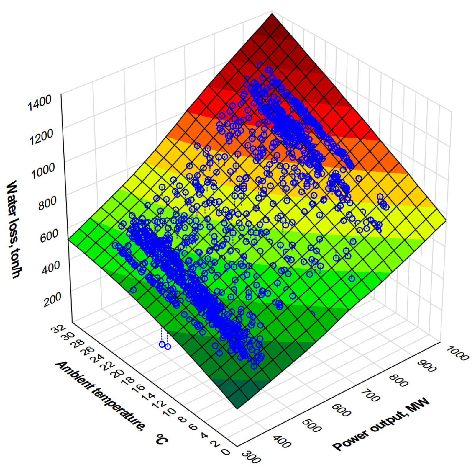
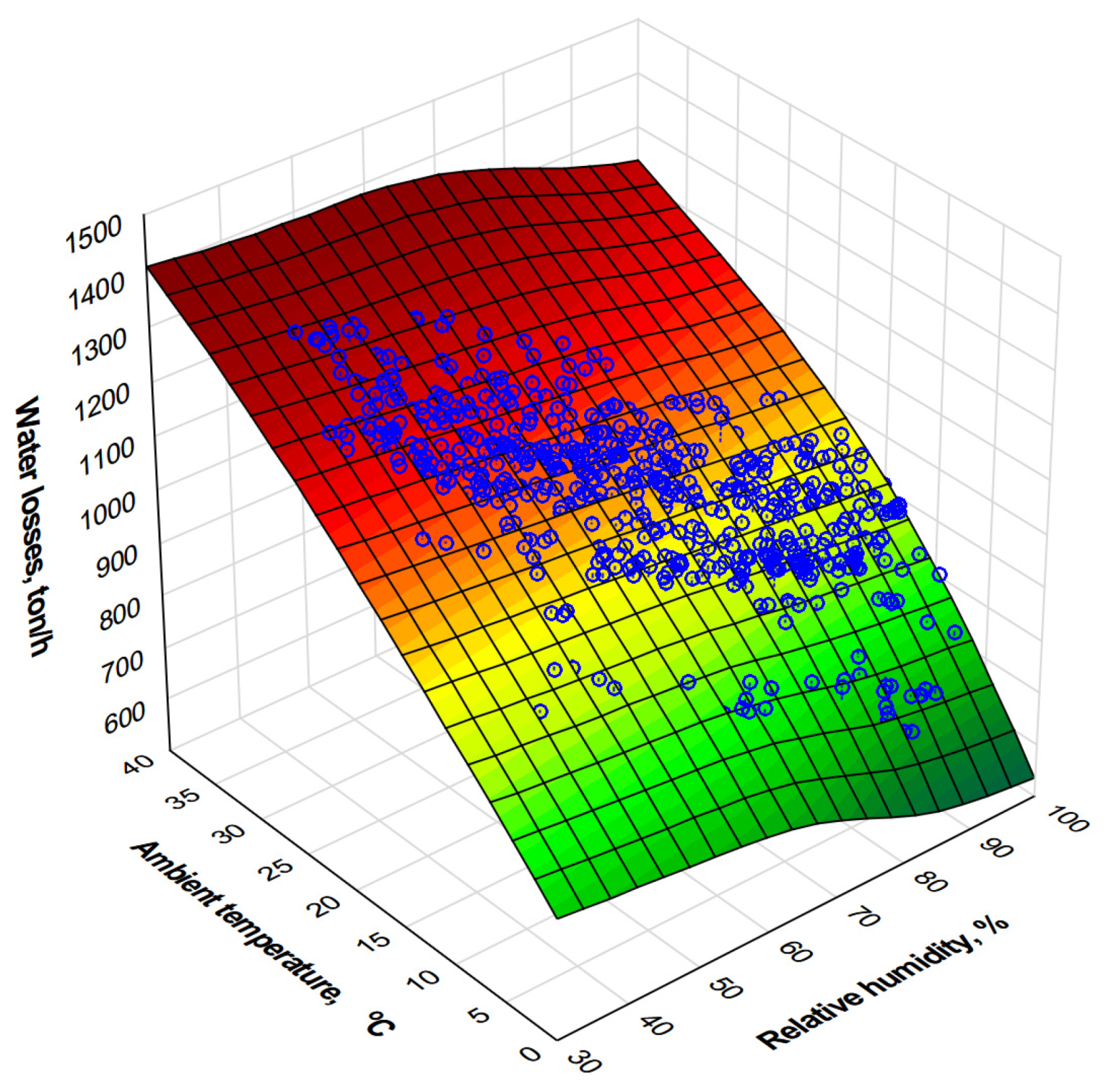
The calculations allow to determine the water loss flux due to evaporation and to determine the effect of ambient conditions and power unit load on its value. This information is very important when the conditions in which the cooling tower operates differ from the design assumptions. This is especially true for cooling tower operation at high temperatures and humidity when the power unit is operating at maximum load. The results make it possible to formulate an approximation function defining the dependence of evaporative loss on the unit power as well as on the temperature and humidity of ambient air. The feature can be helpful in forecasting water usage within a power unit.
(b)
Based on the measured data, the total water loss due to evaporation and drift is determined and expressed as a function of ambient temperature and unit power. After subtracting the water loss due to evaporation, the drift loss is determined. The drift loss is found to be at 100–300 ton/h, i.e., approximately 0.125–0.375% of the cooling water flux and increases slightly with increasing ambient temperature Tamb and increasing unit power.
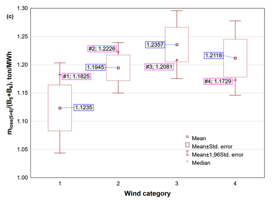
(c)
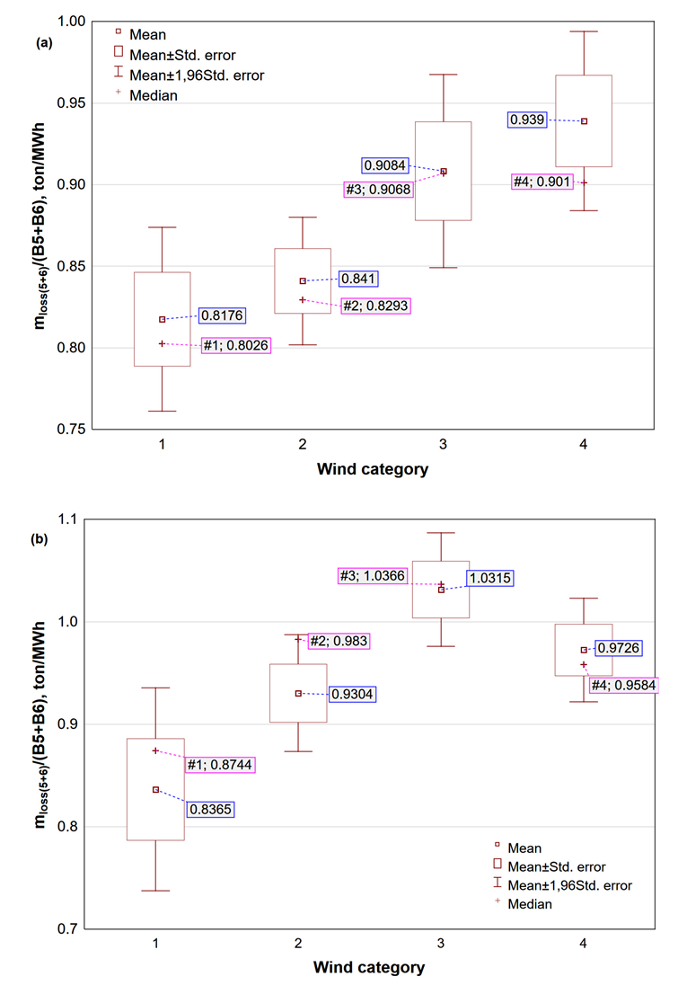
The effect of wind on total water loss due to evaporation and drift is investigated. Its value is determined for the cooling tower and related to the generated power. The measurement results are given and the calculations are performed for three different values of Tamb, i.e., 7 °C, 15 °C, 22 °C. This effect is found to be statistically significant and the loss so determined, in general, increases with wind speed. This is evident for ambient temperature of 7 °C. In other cases, in each of the wind speed categories, the loss is greater than in case, when the wind speed is in the range between 0–1 m/s. The loss of cooling water related to the power unit increased to 14.8% for the temperature of Tamb 7 °C and to 23.3% for Tamb 15 °C. For Tamb 22 °C, the maximum increase of this loss was about 10%.
(d)
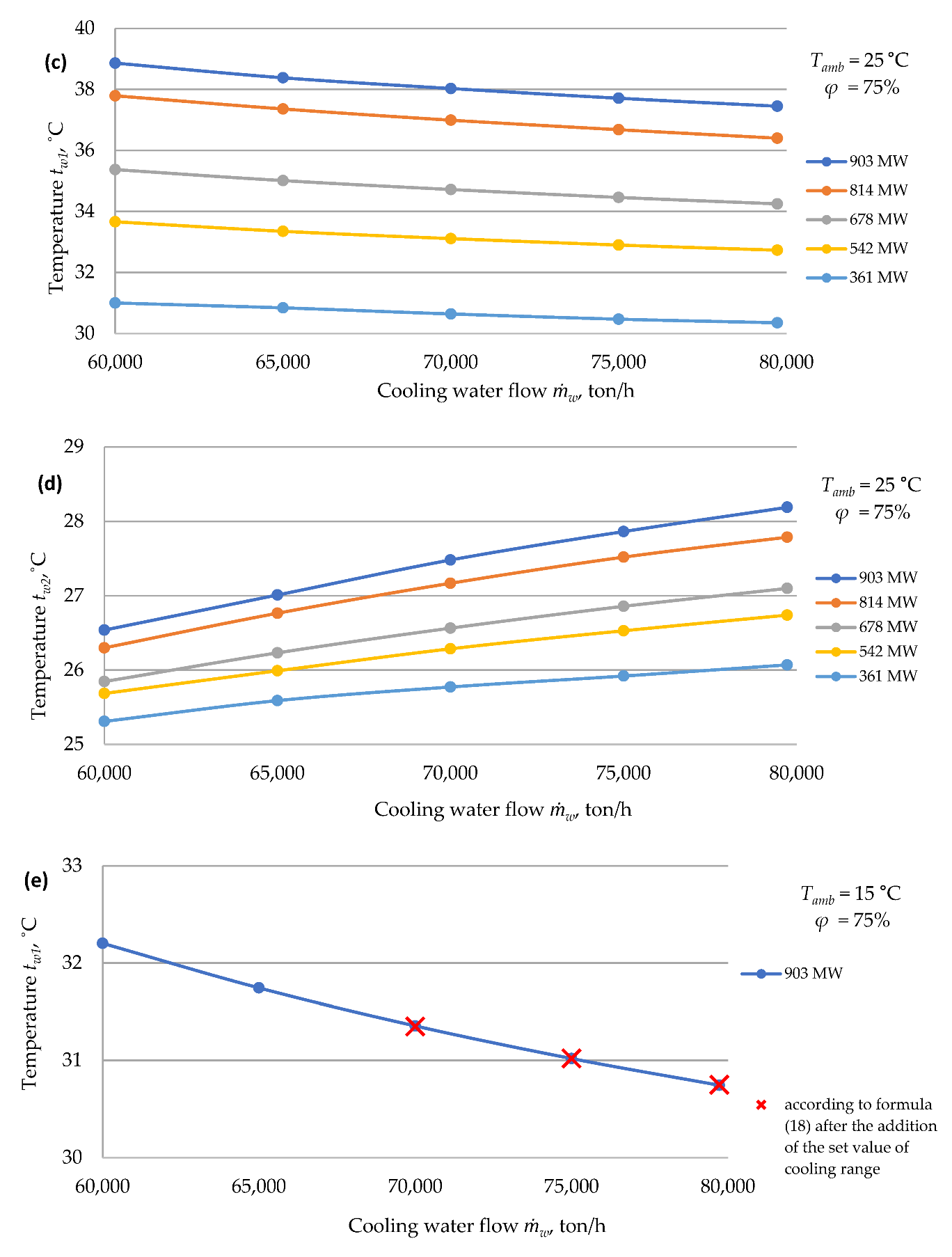
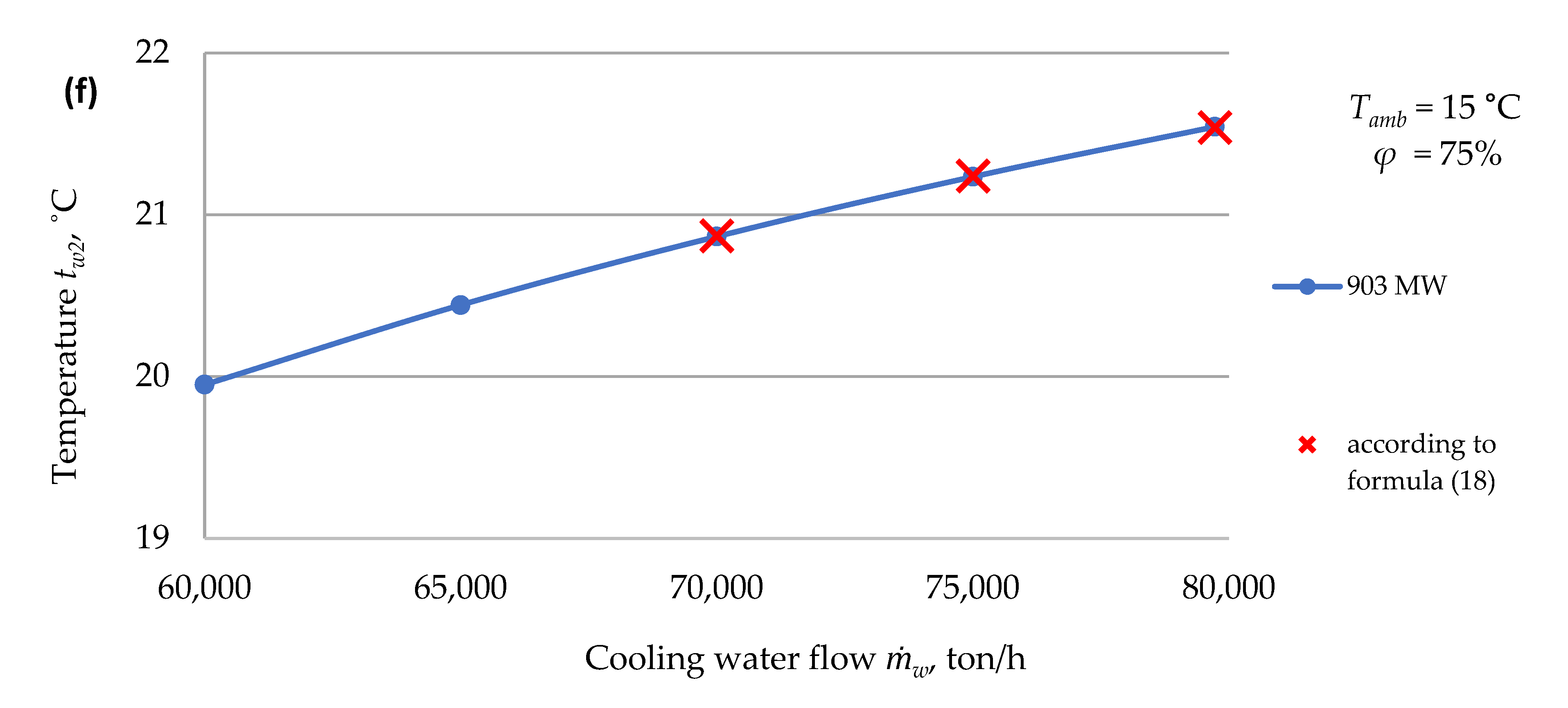
The effect of change in the cooling water flux on the power unit operation is investigated. As the cooling water flux decreases, the water temperature tw1 increases, which has a negative effect on the turbine power output by increasing Ts and ps. In the analysed range of changes in m ˙ w , as the chilled water flux w decreases, the chilled water temperature tw2 decreases. This may be due to the decreasing resistance to airflow through the cooling tower and the change in the ratio m ˙ a m ˙ w . In terms of changes in water flux w from 80,000 ton/h to 60,000 ton/h, tw2 decreases by about 1.5 °C for B = 903 MW and Tamb = 25 °C and by about 0.75 °C at 361 MW and Tamb = 25 °C Similar ranges of change occur for other ambient temperatures Tamb.
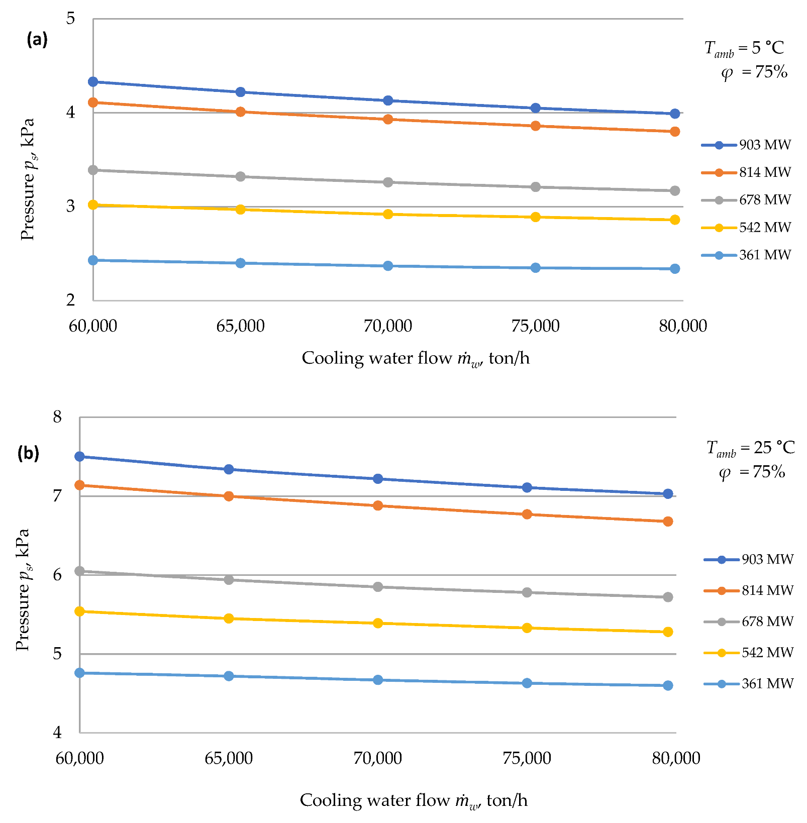
(e)
The condenser vapour pressure value is most significantly affected by the power unit load and ambient temperature. In the range of changes analysed, the effect of w on ps is clearly smaller. At Tamb = 25 °C, the range of these changes is 0.5 kPa for the power of 903 MW and 0.16 kPa for the lowest power of 361.7 MW. At Tamb = 5 °C, these changes are 0.34 kPa and 0.08 kPa, respectively. In the range of changes in w analysed, their effect on water loss due to evaporation is also negligibly small and less than 0.5% of ev.
(f)
Figure 12 shows the changes in turbine generator unit power resulting from the increase in condenser pressure. At extremely different temperatures Tamb and thus ps, the reduction in turbine generator unit power can be 8–10% of the rated value. The calculations also show that at low power unit loads of 360–400 MW and at low temperatures Tamb, less than 10 °C, it is possible to reduce the cooling water flux and obtain an increase in the net power of the unit. This increase is due to a reduction in cooling water pump power. This issue requires further studies for the power units analysed.

Author Contributions

Conceptualization, J.P.; methodology, J.P.; validation, M.P. and R.S.; formal analysis, A.K. and K.W.; investigation, Z.B.; data curation, Z.B., R.C. and A.D.; writing—original draft, J.P.; writing—review and editing, A.K., R.C. and A.D.; visualization, Z.B. and K.W.; supervision: M.P. and R.S. All authors have read and agreed to the published version of the manuscript.

Funding

This research received no external funding.

Institutional Review Board Statement

Not applicable.

Informed Consent Statement

Not applicable.

Data Availability Statement

The data presented in this study are available on request from the corresponding author. The data are not publicly available due to their commercial nature.

Acknowledgments

The authors would like to thank the Management of PGE, Opole Power Plant for providing the measurement data and other documentation.

Conflicts of Interest

The authors declare no conflict of interest.

Abbreviations

Latin Symbols:
Bpower output (in general), [MWe]
B5, B6power output of power unit no. 5/6, [MWe]
cwspecific heat of water, [kJ/(kg K)]
Finner surface area of the cooling tower shell at the top edge of the air inlet [m2]
FrFroude number
gEarth’s acceleration, [m/s2]
Heeffective height of the cooling tower [m]
ia1, ia2air enthalpy at the inlet/outlet to the cooling tower, [kJ/kg]
ia,iair enthalpy, [kJ/kg]
ia,mair average enthalpy, [kJ/kg]
iaair enthalpy in the fillings, [kJ/kg]
iLPenthalpy of LP-steam [kJ/kg]
INatmospheric coefficient,
aair flux, [m3/h]
evevaporative loss flux, [ton/h]
lossevaporation and drift loss fluxes, [ton/h]
LPsteam flux from LP-part of turbine [ton/h]
wcooling water flux, [ton/h]
sboiler fresh steam flux, [kg/s]
MeMerkel number
psteam pressure, [MPa]
pbbarometric pressure, [Pa]
pssaturation pressure, [Pa]
Q ˙ s heat flux from condensing steam to cooling water [W]
Ta,mair average temperature, [°C]
Tambambient temperature, [°C]
TLPtemperature of steam from the LP part of the turbine, [°C]
T a m temperature of steam-saturated air above the fillings [°C]
tw,maverage water temperature, [°C]
tw1, tw2inlet/outlet water temperature at the cooling tower, [°C]
wmaverage air velocity under the cooling tower fillings, [m/s]
Xa,iair moisture of air surrounding the cooling towers
Xa,mair moisture of saturated air
FDGFlue Gas Desulfurization
RHrelative humidity, [%]
NDWCTnatural draft wet cooling tower
NDHCTnatural draft hybrid cooling tower
CCScarbon capture and storage
CSPconcentrating solar power
WTPwater treatment plant
LPlow pressure part of steam turbine
Greek Symbols:
increment symbol
ηepower unit net efficiency
Λnumber of ventilations
ζcoefficient of resistance to air flow through the cooling tower
φrelative air humidity, [%]
ρa1, ρa1air density at the inlet/outlet to the cooling tower, [kg/m3]
ρamair average density of moist air in front of the cooling tower and above the fillings, [kg/m3]
ρasmdry air average density, [kg/m3]

References

  1. Macknick, J.; Newmark, R.; Heath, G.; Hallett, K.C. Operational water consumption and withdrawal factors for electricity generating technologies: A review of existing literature. Environ. Res. Lett. 2012, 7, 045802. [Google Scholar] [CrossRef]
  2. Xia, L.; Li, J.; Ma, W.; Gurgenci, H.; Guan, Z.; Wang, P. Water Consumption Comparison between a Natural Draft Wet Cooling Tower and a Natural Draft Hybrid Cooling Tower—An Annual Simulation for Luoyang Conditions. Heat Transf. Eng. 2017, 38, 1034–1043. [Google Scholar] [CrossRef]
  3. He, W.; Zhang, J.; Li, H.; Liu, S.; Wang, Y.; Lv, B.; Wei, J. Optimal thermal management of server cooling system based cooling tower under different ambient temperatures. Appl. Therm. Eng. 2022, 207, 118176. [Google Scholar] [CrossRef]
  4. García Cutillas, C.; Ruiz Ramírez, J.; Lucas Miralles, M. Optimum Design and Operation of an HVAC Cooling Tower for Energy and Water Conservation. Energies 2017, 10, 299. [Google Scholar] [CrossRef]
  5. Song, Y.; Wu, G.; Song, B. Analysis of drift loss and concentration change of wet cooling tower. In IOP Conference Series: Earth and Environmental Science; IOP Publishing: Bristol, UK, 2020; Volume 569, p. 012059. [Google Scholar]
  6. Song, B. Numerical analysis on the effects of water spraying on cooling tower evaporation and drift. In IOP Conference Series: Earth and Environmental Science; IOP Publishing: Bristol, UK, 2020; Volume 529, p. 012004. [Google Scholar]
  7. Rubio-Castro, E.; Serna-González, M.; Ponce-Ortega, J.M.; Morales-Cabrera, M.A. Optimization of mechanical draft counter flow wet-cooling towers using a rigorous model. Appl. Therm. Eng. 2011, 31, 3615–3628. [Google Scholar] [CrossRef]
  8. Gao, M.; Zou, J.; He, S.; Sun, F. Thermal performance analysis for high level water collecting wet cooling tower under cross wind conditions. Appl. Therm. Eng. 2018, 136, 568–575. [Google Scholar] [CrossRef]
  9. Zhang, Z.; Gao, M.; Wang, M.; Guan, H.; Dang, Z.; He, S.; Sun, F. Field test study on thermal and ventilation performance fornatural draft wet cooling tower after structural improvement. Appl. Therm. Eng. 2019, 155, 305–312. [Google Scholar] [CrossRef]
  10. Alavi, S.R.; Rahmati, M. Experimental investigation on thermal performance of natural draft wet cooling towers employing an innovative wind-creator setup. Energy Convers. Manag. 2016, 122, 504–514. [Google Scholar] [CrossRef]
  11. Lu, Y.; Guan, Z.; Gurgenci, H.; Hooman, K.; He, S.; Bharathan, D. Experimental study of crosswind effects on the performance of small cylindrical natural draft dry cooling towers. Energy Convers. Manag. 2015, 91, 238–248. [Google Scholar] [CrossRef]
  12. Zhou, Y.; Gao, M.; Long, G.; Zhang, Z.; Dang, Z.; He, S.; Sun, F. Experimental study regarding the effects of forced ventilation on the thermal performance for super-large natural draft wet cooling towers. Appl. Therm. Eng. 2019, 155, 40–48. [Google Scholar] [CrossRef]
  13. Klimanek, A.; Cedzich, M.; Białecki, R. 3D CFD modeling of natural draft wet-cooling tower with flue gas injection. Appl. Therm. Eng. 2015, 91, 824–833. [Google Scholar] [CrossRef]
  14. Wu, T.; Ge, Z.; Yang, L.; Du, X. Flow deflectors to release the negative defect of natural wind on large scale dry cooling tower. Int. J. Heat Mass Transf. 2019, 128, 248–269. [Google Scholar] [CrossRef]
  15. Chen, X.; Sun, F.; Chen, J.; Gao, M. Novel method for improving the cooling performance of natural draft wet cooling towers. Appl. Therm. Eng. 2019, 147, 562–570. [Google Scholar] [CrossRef]
  16. Gao, M.; Sun, F.; Wang, K.; Shi, Y.; Zhao, Y. Experimental research of heat transfer performance on natural draft counter flow wetcooling tower under cross-wind conditions. Int. J. Therm. Sci. 2008, 47, 935–994. [Google Scholar] [CrossRef]
  17. Chen, K.; Sun, F.; Zhang, L.; Chen, X.; Zhang, X. A sensitivity-coefficients method for predicting thermal performance of natural draft wet cooling towers under crosswinds. Appl. Therm. Eng. 2022, 206, 118105. [Google Scholar] [CrossRef]
  18. Zhou, Y.; Wang, K.; Gao, M.; Dang, Z.; He, S.; Sun, F. Experimental study on the drag characteristic and thermal performance of non-uniform fillings for wet cooling towers under crosswind conditions. Appl. Therm. Eng. 2018, 140, 398–405. [Google Scholar] [CrossRef]
  19. Ardekani, M.A.; Farhani, F.; Mazidi, M. Effects of Cross Wind Conditions on Efficiency of Heller Dry Cooling Tower. Exp. Heat Transf. 2015, 28, 344–353. [Google Scholar] [CrossRef]
  20. Lu, Y.; Guan, Z.; Gurgenci, H.; Alkhedhair, A.; He, S. Experimental investigation into the positive effects of a tri-blade-like windbreak wall on small size natural draft dry cooling towers. Appl. Therm. Eng. 2016, 105, 1000–1012. [Google Scholar] [CrossRef]
  21. Lucas, M.; Martínez, P.J.; Viedma, A. Experimental determination of drift loss from a cooling tower with different drift eliminatorsusing the chemical balance method. Int. J. Refrig. 2012, 35, 1779–1788. [Google Scholar] [CrossRef]
  22. Buryn, Z.; Kuczuk, A.; Pospolita, J.; Smejda, R.; Widera, K. Impact of Weather Conditions on the Operation of Power Unit Cooling Towers 905 MWe. Energies 2021, 14, 6412. [Google Scholar] [CrossRef]
  23. He, S.; Gurgenci, H.; Guan, Z.; Hooman, K.; Zou, Z.; Sun, F. Comparative study on the performance of natural draft dry, pre-cooled and wet cooling towers. Appl. Therm. Eng. 2016, 99, 103–113. [Google Scholar] [CrossRef]
  24. Zembaty, W. Systemy i Urządzenia Chłodzące Elektrowni Cieplnych [Cooling Systems and Devices of Thermal Power Plants]; WNT: Warsaw, Poland, 1993; p. 337. (In Polish)
  25. Picardo, J.R.; Variyar, J.E. The Merkel equation revisited: A novel method to compute the packed height of a cooling tower. Energy Convers. Manag. 2012, 57, 167–172. [Google Scholar] [CrossRef]
  26. Yuan, W.; Sun, F.; Liu, R.; Chen, X.; Li, Y. The Effect of Air Parameters on the Evaporation Loss in a Natural Draft Counter-Flow Wet Cooling Tower. Energies 2020, 13, 6174. [Google Scholar] [CrossRef]
  27. Badanie Wilgotności Gazów na Przykładzie Powietrza [Testing the Moisture of Gases Using Air as an Example]. Available online: http://home.agh.edu.pl/~{}pawelzak/lab/badanie_wilg_gazow.pdf (accessed on 15 May 2021).
  28. Kruskal, W.H.; Wallis, W.A. Use of ranks in one-criterion variance analysis. J. Am. Stat. Assoc. 1952, 47, 583–621. [Google Scholar] [CrossRef]
  29. Corder, G.W.; Foreman, D.I. Nonparametric Statistics for Non-Statisticians; John Wiley & Sons: Hoboken, NJ, USA, 2009; pp. 99–105. [Google Scholar]
  30. Divine, G.W.; Norton, H.J.; Barón, A.E.; Juarez-Colunga, E. The Wilcoxon–Mann–Whitney Procedure Fails as a Test of Medians. Am. Stat. 2018, 72, 278–286. [Google Scholar] [CrossRef]
  31. Radzik, T.; Miełek, Ł.; Cholewa, R.; Kusa, M. Report on the In-Service Measurements of Power Unit 5 in PGE GiEK S.A. Opole Power Plant Branch, Part 1/5. Turbogenerator and Power Unit Thermal Measurements. Ref. No. 120/ZC/2021. ZP-BE Energopomiar Sp. z o.o. Gliwice; Energopomiar: Gliwice, Poland, 2021. (In Polish) [Google Scholar]
  32. Miełek, Ł.; Cholewa, R.; Kusa, M. Report on the Measurements to Determine the Characteristics of the Influence of the Outlet Steam Pressure Change on the Power and Specific Heat Consumption of Power Units no. 5 and 6 in PGE GiEK S.A. Opole Power Plant Branch. No. 169/ZC/2021. ZP-BE Energopomiar Sp. z o.o. Gliwice; Energopomiar: Gliwice, Poland, 2021. (In Polish) [Google Scholar]
  33. Standard EN 14705:2005; Heat Exchangers—Method of Measurement and Evaluation of Thermal Performances of Wet Cooling Towers. Comite Europeen de Normalisation: Brussels, Belgium, 2015.
Figure 1. Water consumption in the power generation process (water replenishment in the cooling circuit is shown in blue, water replenishment in the boiler circuit is shown in green).
Energies 15 05969 g001
Figure 2. Schematic diagram of a 905 MW power unit with water system for cooling and boiler circuit.
Energies 15 05969 g002
Figure 3. Dependence of water losses due to evaporation on the function of the unit power output and ambient temperature (φ = 70 ± 5%).
Energies 15 05969 g003
Figure 4. Dependence of water losses due to evaporation on the function of ambient temperature, relative humidity (B = 400 ± 10 MW).
Energies 15 05969 g004
Figure 5. Dependence of water losses due to evaporation on the function of ambient temperature, relative humidity (B = 900 ± 10 MW).
Energies 15 05969 g005
Figure 6. Effect of unit power and ambient temperature on the sum of evaporative and drift losses.
Energies 15 05969 g006
Figure 7. Drift loss as a function of the unit power output and ambient temperature (φ = 70 ± 10%).
Energies 15 05969 g007
Figure 8. Water losses due to evaporation and drift related to the power of units for humidity φ = 70 ± 5% and ambient temperature: (a) Tamb = 7 ± 1 °C; (b) Tamb = 15 ± 1 °C; (c) Tamb = 22 ± 1 °C (symbol #+number means wind category).
Energies 15 05969 g008aEnergies 15 05969 g008b
Figure 9. Temperatures tw1 and tw2 as a function of unit power output and Tamb =15 ± 1 °C, φ = 70 ± 5%: (a) for power unit 5; (b) for power unit 6.
Energies 15 05969 g009
Figure 10. Temperature values at the inflow tw1 and outflow tw2 to/from the cooling tower as a function of cooling water flux for ambient temperature: (a,b) 5 °C; (c,d) 25 °C; (e,f) after considering the results obtained using Formula (18).
Energies 15 05969 g010aEnergies 15 05969 g010bEnergies 15 05969 g010c
Figure 11. Effect of water flux on steam pressure in turbine condenser for air temperature: (a). Tamb = 5 °C, (b) Tamb = 25 °C.
Energies 15 05969 g011
Figure 12. Dependence of unit power on fresh steam flux and condenser pressure for different values of fresh steam flux (theoretical curves are marked with lines, and in-service measurement results are marked with points).
Energies 15 05969 g012
Table 1. Mean values of selected parameters presented on Figure 8a–c and Kruskal-Wallis test statistic values and median test for values of m ˙ loss ( 5 + 6 ) B 5 + B 6 .
Wind SpeedNumber
of Data
Mean Valuesp-Value
Tamb = 7 ± 1 °CB5 + B6loss(5 + 6)tw2 m ˙ loss ( 5 + 6 ) B 5 + B 6
1287.006909.304742.59915.8500.818
2697.0721054.557885.60515.8350.841
3406.8961090.670981.19216.2890.908
4277.0351141.9131042.28316.3860.939
testKruskal-WallisH(3) = 13.0509 0.0045
Mediadf = 3; χ2 = 11.9345 0.0076
Wind SpeedNumber
of Data
Mean Valuesp-value
Tamb = 15 ± 1 °CB5 + B6loss(5 + 6)tw2 m ˙ loss ( 5 + 6 ) B 5 + B 6
13314.816910.027797.71521.3000.837
28915.0151244.2891180.55921.2610.930
36015.2111235.2321260.13021.1691.032
43514.9281170.5161124.71820.3730.973
testKruskal-WallisH(3) = 12.4542 0.0060
Median df = 3; χ2 = 8.65443 0.0343
Wind SpeedNumber
of Data
Mean Valuesp-value
Tamb = 22 ± 1 °CB5 + B6 m ˙ l o s s ( 5 + 6 ) tw2 m ˙ l o s s ( 5 + 6 ) B 5 + B 6
14522.0391076.7751221.59625.3831.124
213821.9311171.8481383.29225.3931.195
37421.8891282.6041546.71325.2001.236
42821.8001317.0311564.84825.1121.212
testKruskal-WallisH(3) = 1.70131 0.6366
Mediandf = 3; χ2 = 2.17466 2.17466 0.5370
Publisher’s Note: MDPI stays neutral with regard to jurisdictional claims in published maps and institutional affiliations.

