Abstract
Permanent-magnet (PM) width-modulation array is designed to solve the issues resulting from big pole-pitches of PMLSMs in high-speed and high-precision systems. PM width-modulation array provided in this paper is a kind of segmented magnetic-pole structure, featuring low PM eddy currents and low thrust ripples. First, the magnetomotive force (MMF) excited by the PM width-modulation array is analyzed to prove its feasibility, the PM eddy current of the novel array is studied to show its advantage in high-speed applications, and the electromagnetic models of two PM width-modulation arrays are established, which are designed by the equal area method and the triangular modulation method, respectively. Then, the thrust features and the PM usage amounts of the two PM width-modulation arrays are analyzed by the finite element method (FEM) and the performance comparisons are presented. The prototype is manufactured and tested to verify the analytical results. The experimental data agree well with the simulations and analyses.
1. Introduction
Permanent magnet linear synchronous motor (PMLSM) has a broad application prospect in the high-speed and high-precision systems such as high-performance laser machining and additive manufacturing. For PMLSMs, their speeds are proportional to the synchronous frequencies and the pole pitches. Excessive increases of the synchronous frequencies cause serious problems, so high-speed PMLSMs generally employ big pole pitches. However, big pole-pitch PMLSMs with conventional secondary structures also have the issues of high PM eddy current loss, low secondary mechanical strength, manufacture difficulties, and so on [1,2,3].
The magnetic pole segmented along the longitudinal direction employs several permanent magnets (PMs) per pole to replace one PM per pole. The longitudinal lengths and volumes of PMs are greatly reduced, then the PM eddy current losses and the manufacture difficulties are suppressed [4,5]. Further, the materials and the constructions of the fillers among PMs per pole can be optimized to improve the secondary mechanical strength [6]. Thus, the segmented magnetic pole structures are preferred by the high-speed PMLSMs.
Though the segmented magnetic pole structures can effectively solve the issues from the big pole-pitches of high-speed PMLSMs, they lead to the increases of the thrust ripple. Low thrust ripples are very important for the high-precision systems [7]. Thus, a segmented magnetic pole structure featuring a low thrust ripple is the technical challenge for the high-speed and high-precision PMLSMs. Skew poles [8,9], eccentric poles [10], and Halbach array [11] all have been used in the segmented magnetic pole structure to reduce the thrust ripple. However, the decrease of the average thrust and the increase of manufactory cost are their drawbacks. The PM width-modulation array presented in this paper adopts a group of same-polarity PMs to excite the main magnetic field per pole. This novel secondary, as a kind of segmented magnetic pole structure, can help reduce the thrust ripple while solving the issues from big pole-pitches [4].
In ref. [4], the topology of PM width-modulation array is designed, and the average thrust of PMLSM with this novel array can reach the thrust level of motors with the conventional non-salient pole secondaries. This paper calculates the PM eddy current in this novel array; the PM eddy current in a conventional non-salient pole secondary is employed for comparison and it is found that two methods can be used to design the PM width-modulation array after further studies: the equal area method and the triangular modulation method. The analyses and comparisons of the two PM width-modulation arrays designed by the two different methods are the focus of this paper.
The paper is organized as follow: Section 2 provides the magnetomotive force (MMF) of the PM width-modulation array and calculates its PM eddy current; electromagnetic models of two PM width-modulation arrays, designed by the equal area method and the triangular modulation method respectively, are studied in Section 3 and Section 4; Section 5 compares the thrust characteristics and the PM usage amounts of two PM width-modulation arrays. Experimental validation is presented in Section 6.
2. Electromagnetic Performance of PM Width-Modulation Array
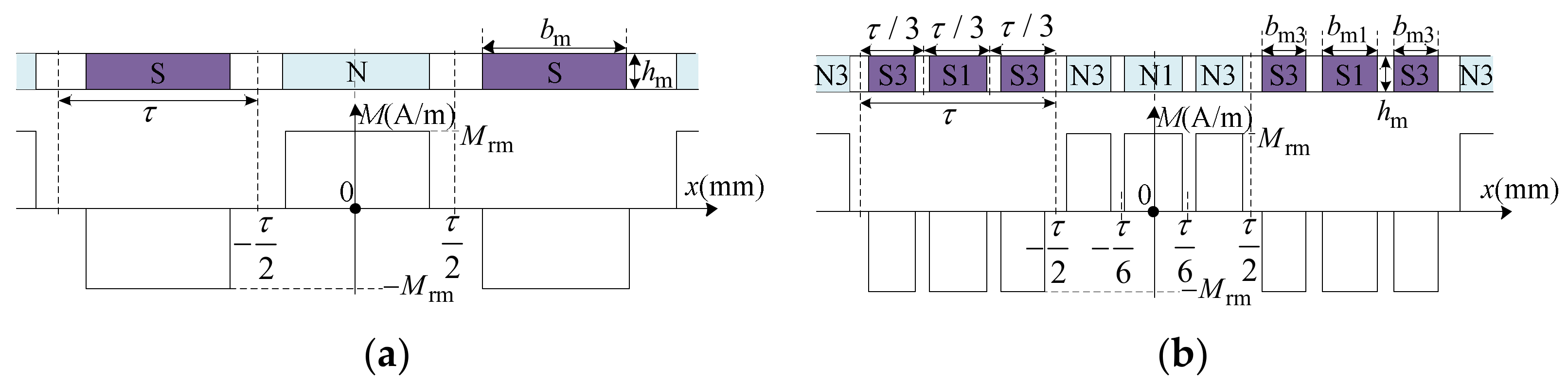
For PMLSM, the main magnetic field excited by PMs in its secondary interacts with the armature magnetic field induced by the currents in its primary to generate the electromagnetic force. The main magnetic field is stronger than the armature magnetic field, so the thrust features of PMLSM are greatly influenced by the electromagnetic structure of its magnetic pole. For the conventional non-salient pole secondary, there is only one PM per pole, as shown in Figure 1a. M is the distribution of the magnetization intensity, Mrm is the amplitude of M. The pole pitch of PMLSM is τ, the longitudinal (Direction x) length of PMs is bm, and the normal (Direction y) length of PMs is hm. For the PM width-modulation array, there are s PMs to excite the main magnetic field per pole, s is the carrier ratio of this novel array. Figure 1b shows a PM width-modulation array with s = 3, 3 PMs per pole have two kinds of longitudinal lengths which are noted as bm1 and bm3.
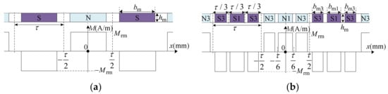
Figure 1.
Secondary structures of PMLSMs: (a) conventional non-salient pole secondary; (b) PM width-modulation array with a carrier ratio s = 3.
The PM width-modulation array with a carrier ratio of s has s PMs per pole, and their longitudinal lengths are different.
If the carrier ratio s is an even number, the labels of the PMs per pole are the even numbers in the range from 2 to s, their longitudinal lengths are bm2······bms. These can be noted as bmr, and r is an even number ranging from 2 to s.
If the carrier ratio s is an odd number, the labels of the PMs per pole are the odd numbers in the range from 1 to s, their longitudinal lengths are bm1, bm3······bms. These can be noted as bmr, and r is an odd number ranging from 1 to s.
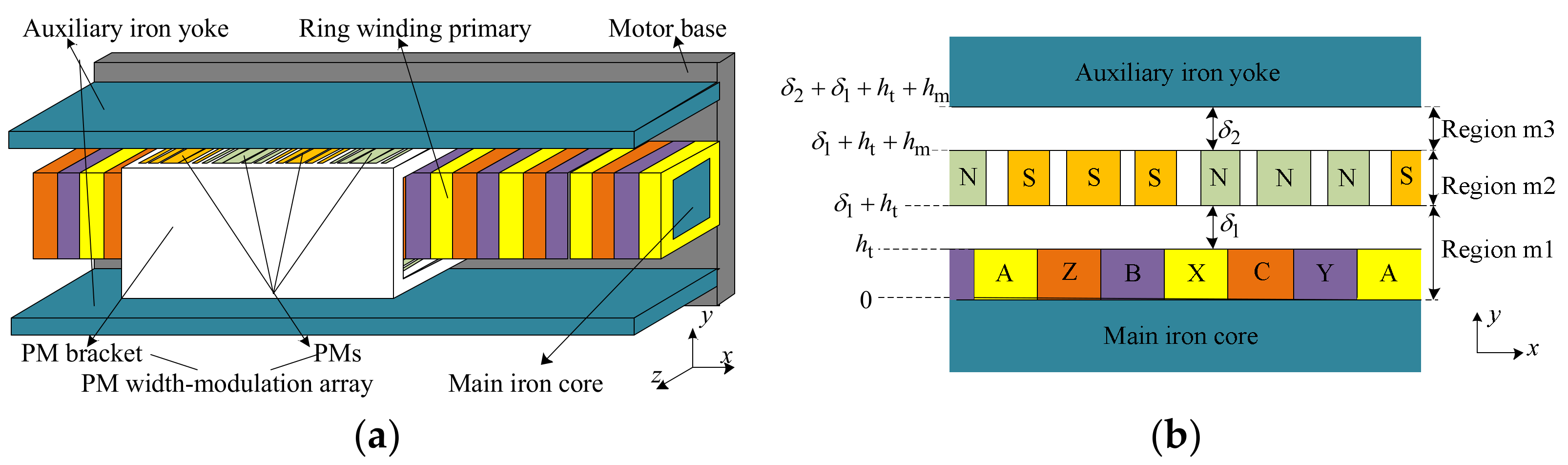
As a novel magnetic-pole array, the feasibility of the PM width-modulation array should be verified first; its MMF is analyzed here. In addition, the PM width-modulation array is a segmented magnetic pole structure, the reduction of the PM eddy current is one of its important advantages, so the analysis of PM eddy current in this PM width-modulation array is provided in this section. The model of a double-sided PMLSM with a PM width-modulation array, exhibited in Figure 2, is employed to study the performances of this novel structure.

Figure 2.
Model of the double-sided PMLSM with the PM width-modulation array: (a) motor structure, (b) unilateral analytical model for electromagnetic field.
2.1. Magnetomotive Force
Based on Kirchhoff’s law of magnetic circuit, the sum of MMFs is identical with the sum of the magnetic potential differences, along any closed magnetic circuit. For the no-load state of the PMLSM model in Figure 2, the only source of MMF is the PMs. Thus, the sum of the magnetic potential differences along the main magnetic circuit in the no-load state is equal to the MMF excited by the PM width-modulation array. The permeability of iron materials can be considered as infinity, so the magnetic potential differences in the main iron core and the auxiliary iron can be not counted. The MMF excited by the PM width-modulation array is the sum of the magnetic potential differences in Region m1, Region m2, and Region m3 for the analytical model shown in Figure 2b.
The normal length of the winding is ht, the length of mechanical air gaps on the armature sides is δ1, the length of mechanical air gaps on the auxiliary iron yoke sides is δ2. The feasibility verification takes the case of s = 3. Br is the PM remanence, n is the harmonic order, μ0 is the vacuum permeability, and is the modulation factor of the PM width-modulation array with s = 3. The magnetic field intensities of Region m1, Region m2, and Region m3 are Hw3m1y, Hw3m2y, and Hw3m3y,
where , , , , .
The integrals of Hw3m1y, Hw3m2y, and Hw3m3y along Direction y (which is the normal direction in this PMLSM) are the magnetic field intensities of Region m1, Region m2, and Region m3, respectively. Therefore, the sum of the integrals of Hw3m1y, Hw3m2y, and Hw3m3y along Direction y is the MMF Fw3m(x), which is excited by the PM width-modulation array with s = 3. Fw3m(x) can be given by
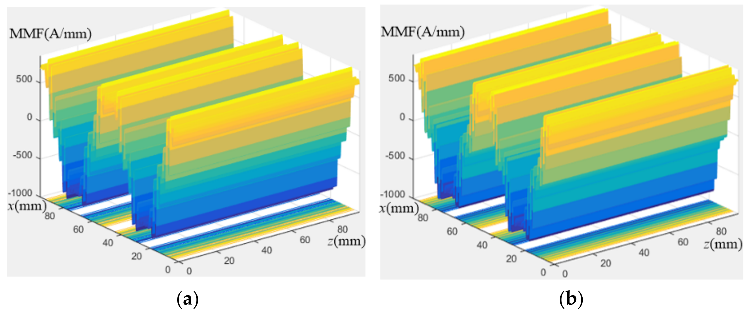
where . From Equation (4), Fw3m(x) is an alternating function with a period of 2τ, it is effective for PMLSM. The MMF of PM width-modulation array always works when the carrier ratio s is various. Figure 3 presents the distributions of MMFs of the PM width-modulation array with s = 9 or 12, where x and z are the longitudinal direction and the transverse direction in PMLSM.
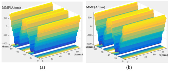
Figure 3.
MMFs of the PM width-modulation array: (a) s = 9, (b) s = 12.
2.2. PM Eddy Current
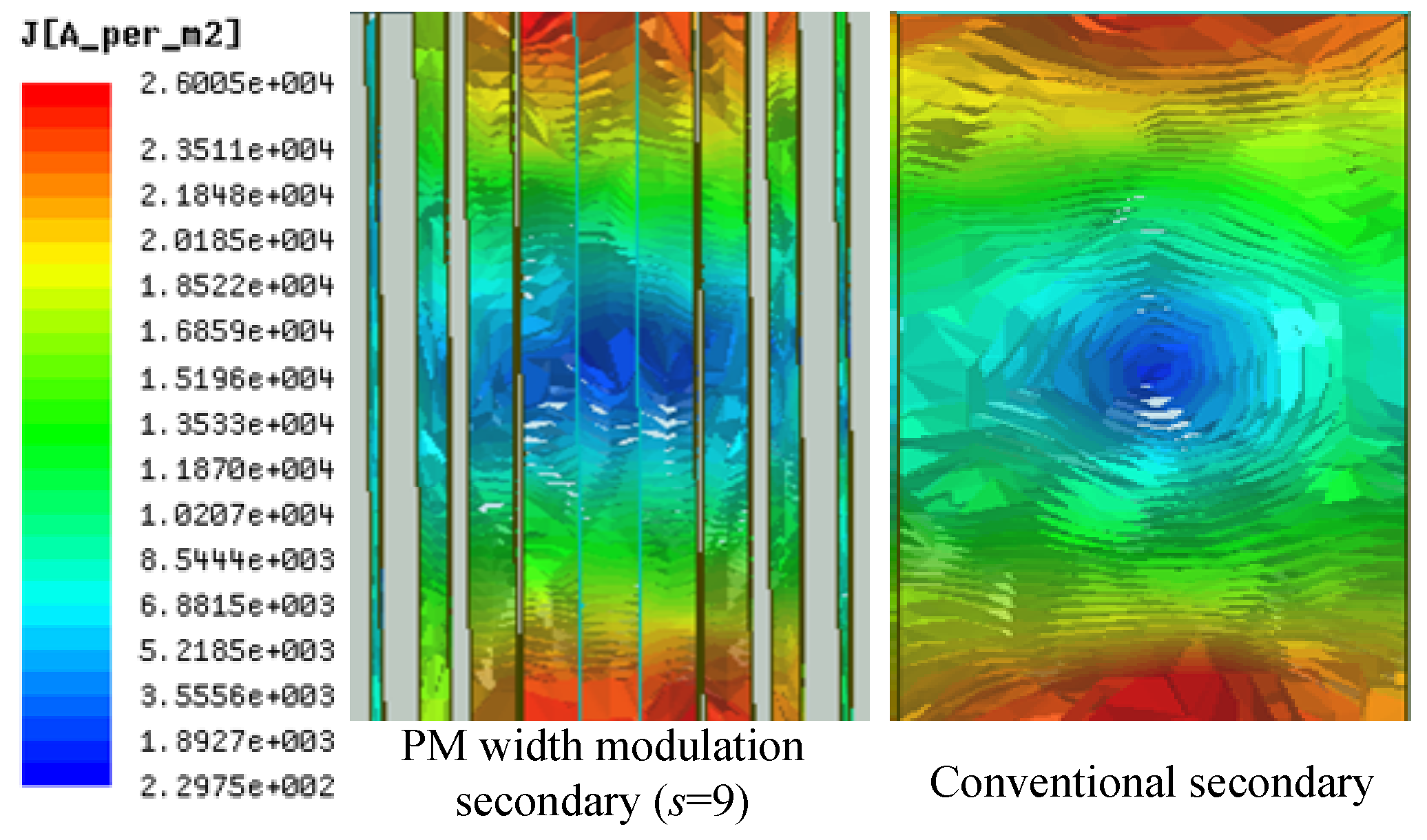
The conventional non-salient secondaries employ one PM per pole. The longitudinal lengths and the volumes of these PMs are large, when the PMLSMs adopt big pole pitches for high speeds. Then, the PM eddy current losses are high. The solution of the segmented magnetic pole structures to the issues of PM eddy currents is enhancing the equivalent resistance of PMs. PM width-modulation array as a kind of segmented magnetic pole structure also has this advantage. PM width-modulation array is composed of the PMs with different longitudinal lengths and the PM bracket. The PM bracket is made from a high mechanical strength material, which has a low electrical conductivity and no magnetic conductivity. The longitudinal lengths and the volumes of these PMs are reduced, and the PM bracket has no magnetic conductivity, so the equivalent resistance of the PM width-modulation array is big, its PM eddy currents loss can be greatly decreased. The PM eddy current of the analytical model in Figure 2 is calculated by FEM method.
For the analytical model, τ = 96 mm and the carrier ratio s = 9. The longitudinal lengths of PMs are 10.51 mm, 9.92 mm, 8.20 mm, 5.43 mm, and 1.91 mm, respectively. The main parameters of the analytical model are listed in Table 1. Another model with a conventional non-salient secondary is taken as a contrast, its pole-arc coefficient is 0.81. Based on the previous study, the conventional non-salient secondary with a pole-arc coefficient of 0.81 has the optimal characteristics.

Table 1.
Main parameters for the analysis of the PM eddy current.
The PM eddy currents in two models are shown in Figure 4.
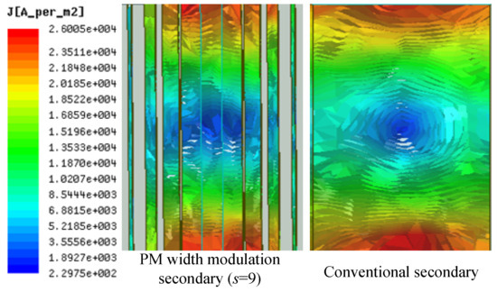
Figure 4.
PM eddy currents of the PM width-modulation array (s = 9) and a conventional secondary.
The PM eddy current in the PM width-modulation array is suppressed obviously compared to the conventional non-salient secondary. For the calculation, the synchronous speed of PMLSMs is 1 m/s, and the rated power is 2.4 kW. The PM eddy current loss of the case with the conventional non-salient secondary is 146.4 W, the one of the case with the PM width-modulation array (s = 9) is only 97.5 W which is only 66.60% of the one in the conventional non-salient secondary case. The advantage of the PM width-modulation array on the PM eddy current loss is very important for high-speed systems.
Two different methods which can be used to design the PM width-modulation array are founded through further research: the equal area method and the triangular modulation method. Their modulation factor Mw(s) is different; Mw(s) is related to the longitudinal lengths and the positions of the PMs, and varies with the carrier ratio s. The modulation factor Mw(s) is marked as Mwe(s) when the PM width-modulation array is designed by the equal area method, and it is labeled as Array I; the modulation factor Mw(s) is marked as Mwu(s) when the PM width-modulation array is designed by the triangular modulation method, and it is labeled as Array II. The detailed analyses are carried out in Section 3 and Section 4.
3. Modeling for Array I
3.1. Electromagnetic Model for Array I
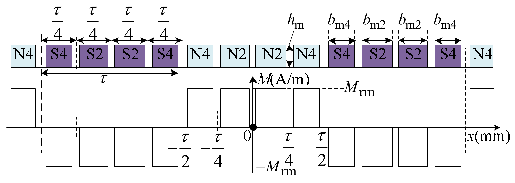
When a carrier ratio of s is adopted by the PM width-modulation array, the region of the main magnetic field per pole is divided into s parts, and only one PM is set in every part. For Array I (the PM width-modulation array designed by the equal area method), the center of the PM overlaps the center of its own part, and the area of the square wave of MMF in every part is equal to the area of the target sine wave imitated by Array I. The target sine wave Mrm1(x) is deduced from the fundamental component (FC) of the main magnetic field excited by the conventional non-salient secondary,
where αpw is the equivalent pole-arc coefficient of Array I. Figure 5 exhibits the structure of Array I with a carrier ratio of 4.
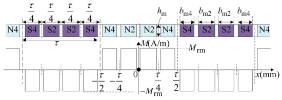
Figure 5.
Structure of Array I with s = 4.
According to the equal area method, the longitudinal lengths of the PMs can be given as
Then, the modulation factor Mwe(s) of Array I is
When the model in Figure 2 is designed by the equal area method, Bwesm1y is the normal component of the magnetic flux density in Region m1, it can be deduced as
Based on this analysis of Array I, its equivalent pole-arc coefficient αpw should take the maximum value. The maximum values of αpw are limited by the special structure of PM width modulation secondary, which are listed in Table 2.
Table 2.
Maximum values of the pole-arc coefficient.
3.2. Characteristic Analysis for Array I
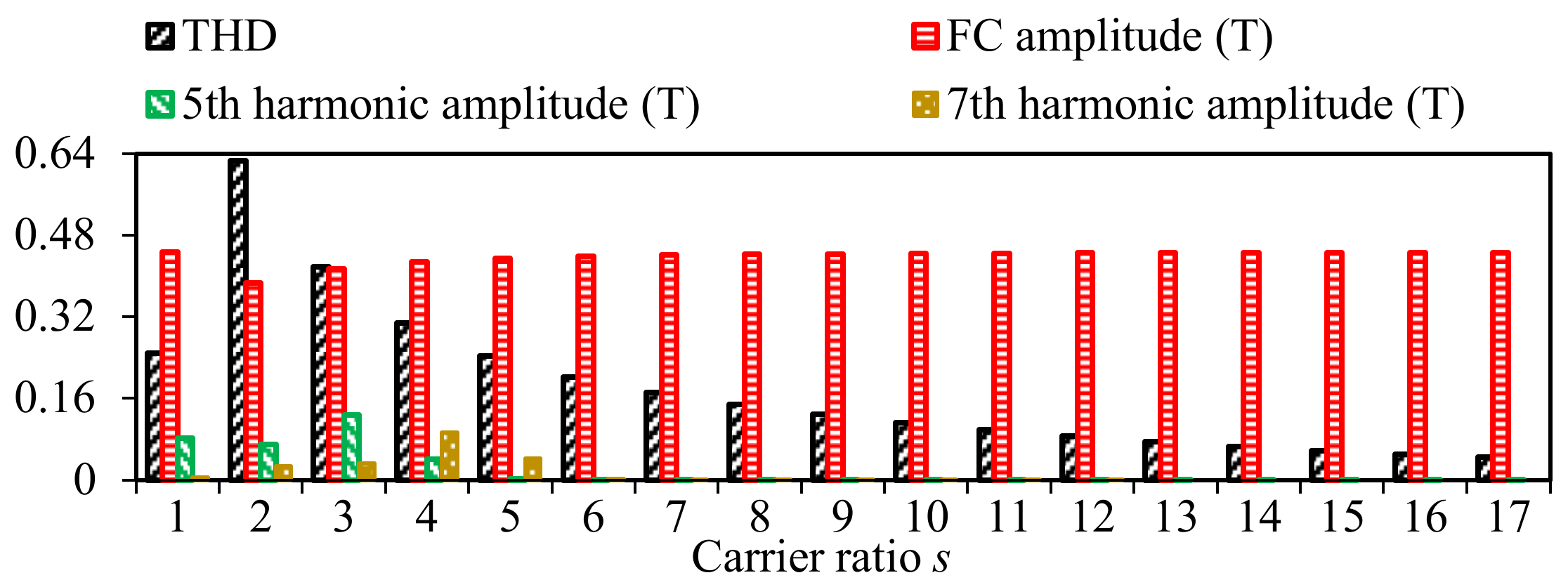
The impacts of the carrier ratio s on Bwesm1y and the thrust features are analyzed here, when the PMLSM in Figure 2 employs Array I. Figure 6 provides the variations of the total harmonic distortion (THD), FC amplitude, and the amplitudes of low-order harmonics of Bwesm1y versus the carrier ratio s. τ = 24 mm and αpw takes the values in Table 2.

Figure 6.
Features of Bwesm1y versus the carrier ratio s for Array I.
The case with s = 1 in Figure 6 is the one with the conventional non-salient secondary, whose pole-arc coefficient is 0.81. This case is chosen as a contrast. Low THD value, low 5th harmonic amplitude, low 7th harmonic amplitude, and high FC amplitude are the goals. For THD value, s should be bigger than 5; for 5th harmonic amplitude, s should be bigger than 3; for 7th harmonic amplitude, s should be bigger than 5; for FC amplitude, s should be as big as possible. Taken together, Array I has the advantage on the features of Bwesm1y over the conventional non-salient secondary when s ≥ 6.
Finite element model (FEM) is established to study the thrust features of PMLSM with Array I. Figure 7 shows the thrust features versus the carrier ratio s. Seen from the data in Figure 7, Array I has the advantage on the thrust features over the conventional non-salient secondary, when s ≥ 6. It is consistent with the analysis on Bwesm1y and the carrier ratio s should be 6, 9, 12, and 15, which are multiples of 3, for a high average thrust and a low thrust ripple ratio.
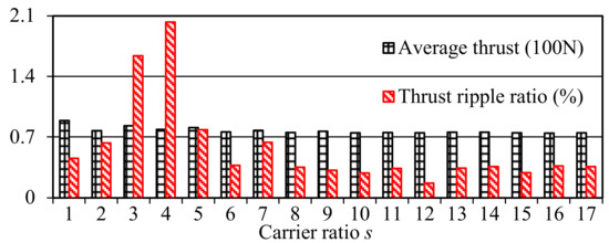
Figure 7.
Thrust features versus the carrier ratio s for Array I.
4. Modeling for Array II
4.1. Electromagnetic Model for Array II
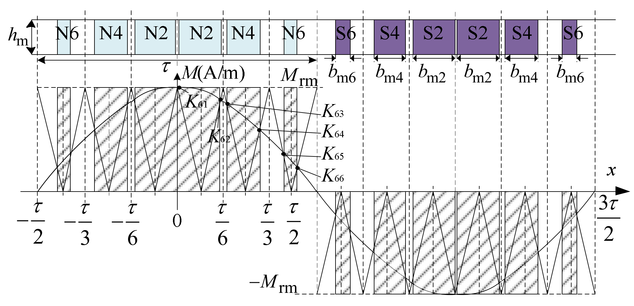
For Array II (the PM width-modulation array designed by the triangular modulation method), a unipolar triangular wave and the target sine wave Mrm1(x) are employed to design the positions and longitudinal widths of PMs. The period of the target sine wave Mrm1(x) is 2τ, and the period of the triangular wave is τ/s. Array II with a carrier ratio of 6 is shown in Figure 8.

Figure 8.
Structure of Array II with s = 6.
In terms of Array II, the center of the PM with a longitudinal length of bmr is Xsr, when 0 ≤ x ≤ τ/2 and the intersection point coordinates of the triangular wave and the target sine wave Mrm1(x) are Ks1, Ks2…Ksr, when 0 ≤ x ≤ τ/2. Then, Xsr= (Ks(r-1) + Ksr)/2 and bmr = Ksr-Ks(r-1). The modulation factor Mwu(s) of Array II can be calculated
When the model in Figure 2 adopts Array II, Bwusm1y is the normal component of the magnetic flux density in Region m1, it can be deduced as
The positions and the longitudinal lengths of PMs in Array II are determined by the intersections of triangular wave and the target sine wave Mrm1(x). The longitudinal lengths of PMs per pole are certain values, they do not vary with the equivalent pole-arc coefficient αpw. The longitudinal lengths of PMs in Array II are listed in Table 3 and Table 4.
Table 3.
Longitudinal lengths of PMs with an even carrier ratio.
Table 4.
Longitudinal lengths of PMs with an odd carrier ratio.
4.2. Characteristic Analysis for Array II
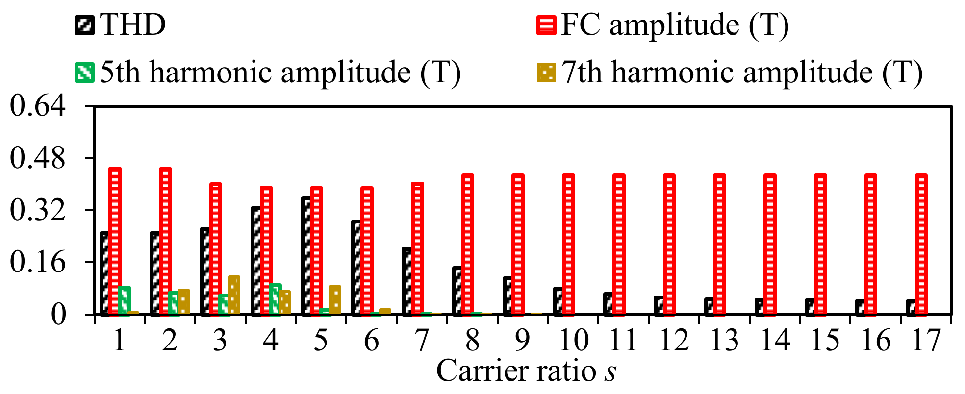
The impacts of the carrier ratio s on Bwusm1y and the thrust features are studied, when the PMLSM in Figure 2 employs Array II. The changes of THD, FC amplitude, and the low-order harmonic amplitudes of Bwusm1y with the carrier ratio s are presented in Figure 9. τ = 24 mm, and the longitudinal lengths of PMs take the values in Table 3 and Table 4.
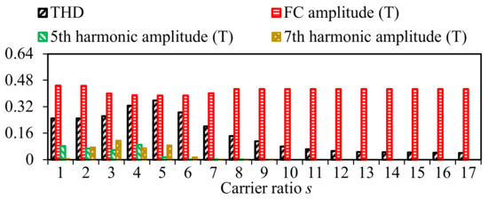
Figure 9.
Features of Bwusm1y versus the carrier ratio s for Array II.
The conventional non-salient secondary case marked as s = 1 in Figure 9 is also the contrast, with a pole-arc coefficient is 0.81. For a low THD and a high FC amplitude, the carrier ratio s of Array II should bigger than 6; in term of 5th harmonic amplitude, s only needs to be bigger than 4; for 7th harmonic amplitude, s only needs to be bigger than 6. In all, the cases with Array II have the advantage on the features of Bwusm1y over the conventional non-salient secondary case when s ≥ 7. The bigger the carrier ratio s is, the better the performance.
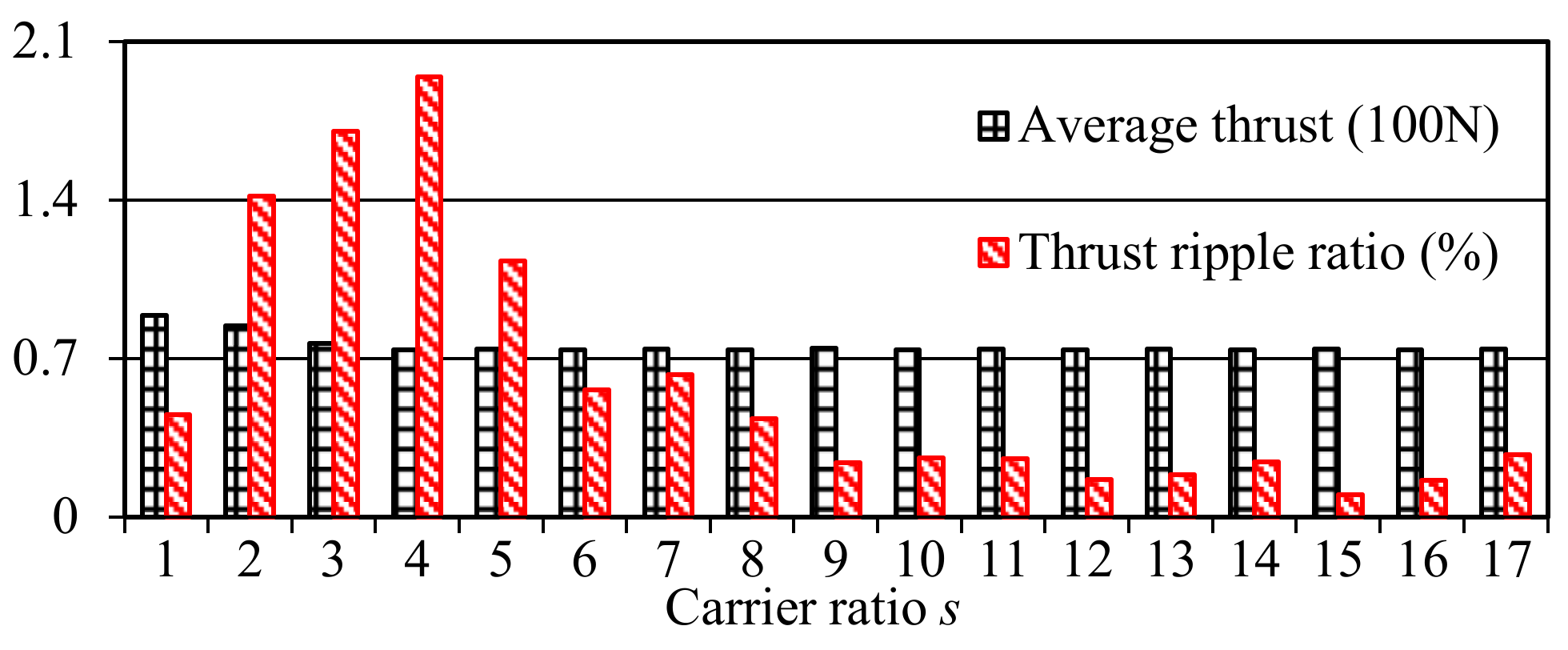
The thrust features obtained by FEM are provided in Figure 10, which change according to the carrier ratio s. It can be seen that Array II has an advantage on the thrust features over the conventional non-salient secondary when s ≥ 8, matching with the analysis of Bwusm1y. For a high average thrust and a low thrust ripple ratio, the carrier ratio s should be as big as possible.
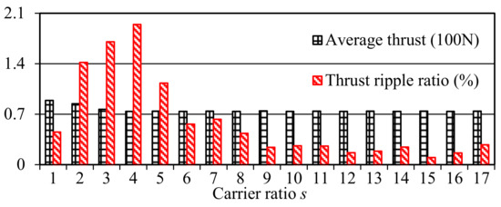
Figure 10.
Thrust features versus the carrier ratio s for Array II.
5. Comparison of Two PM Width-Modulation Arrays
High-speed and high-precision systems have requirements on big pole-pitches and low thrust ripples of the PMLSMs, which are the enable units for these systems. PM usage amounts will increase when the pole-pitches of high-speed PMLSMs are big, except the PM eddy current losses, and the motor thrust ripples should be reduced on the premise that the average thrust is not damaged for the high-precision performance of the applications. Thus, the thrust characteristics and the PM usage amounts of the PMLSMs with two PM width-modulation arrays, designed by the equal area method (Array I) and the triangular modulation method (Array II), are compared here.
5.1. Comparison of Thrust Characteristics
The influences of the carrier ratio s on the average thrusts and the thrust ripple ratios of PMLSMs with two PM width-modulation arrays are presented in Table 5.
Table 5.
Comparison of thrust characteristics of PMLSMs with two PM width-modulation arrays.
Through the comparison of the thrust ripples of two models with Array I and Array II versus the carrier ratio s, the model with Array I has an advantage in reducing the thrust ripple when s is an even number and a multiple of 3, for example s = 12; the model with Array II will be superior to the model with Array I when s is bigger than 9. Thus, Array II has more advantages when the pole pitch of PMLSM is very big.
Based on the analysis of thrust ripple, the carrier ratio s should not be too small. In terms of the average thrust, the performances of two models with Array I and Array II are similar when s is bigger than 8. The average thrust of the model with Array I is slightly higher than the one of the model with Array II. The reason is the equivalent pole-arc coefficient of the model with Array I can be bigger, that is to say, the total volume of PMs in the model with Array I is larger. The usage amounts of PMs in Array I and Array II will be compared in the following part.
5.2. Comparison of PM Usage Amounts
High-speed PMLSMs generally have big pole pitches, the usage amounts of PMs are large, the manufacture costs sharp increase. Therefore, the usage amounts of PMs in two PM width-modulation arrays are calculated here. Through the analysis in Section 5.1, the PM width-modulation arrays have advantages in the thrust ripple and the average thrust when s is bigger than 9 and a multiple of 3. Therefore, the cases of s = 9, 12, and 15 are chosen to calculate the usage amount of PMs. τ = 24 mm, hm = 12 mm, αpw in Array I takes the values in Table 2, and the longitudinal lengths of PMs in Array II takes the values in Table 3 and Table 4. The results are listed in Table 6.
Table 6.
Usage amount of PMs in the PM width-modulation arrays.
The parameters of the contrast case with a conventional non-salient secondary are τ = 24 mm, hm = 10.5 mm, the pole-arc coefficient is 0.81, the average thrust is 77.42 N, the thrust ripple ratio is 0.8218%, and the usage amount of PMs per pole in the contrast case with the conventional non-salient secondary is 204.12 mm3.
Compared to the conventional non-salient secondary case, the average thrusts in the PM width-modulation array cases reach over 95% of the one in the conventional non-salient secondary case, the thrust ripple ratios in the PM width-modulation array cases are much lower than the one in the conventional non-salient secondary case, and the usage amounts of PMs per pole in the PM width-modulation array cases decrease by 10%.
Through the comparisons of the cases with Array I and Array II, the ones with Array I have higher average thrusts and use more PMs, the ones with Array II have lower thrust ripple ratios when s is bigger than 9 and a multiple of 3.
According to the data on FEM analyses in this section and the ones in Figure 6, Figure 7, Figure 9 and Figure 10, these conclusions can be obtained: Array I has a clear advantage on the FC amplitude of the magnetic flux density in Region m1 (the air gap), and has a higher average thrust; for a low THD of the magnetic flux density in Region m1 and a low thrust ripple, Array I has an advantage when 5 ≤ s ≤ 8, and Array II has an advantage when 9 ≤ s; Array II should be chosen when the pole pitch of PMLSM is very large, because the carrier ratio s can be taken as a big value and Array II uses fewer PMs.
6. Prototype and Experiment
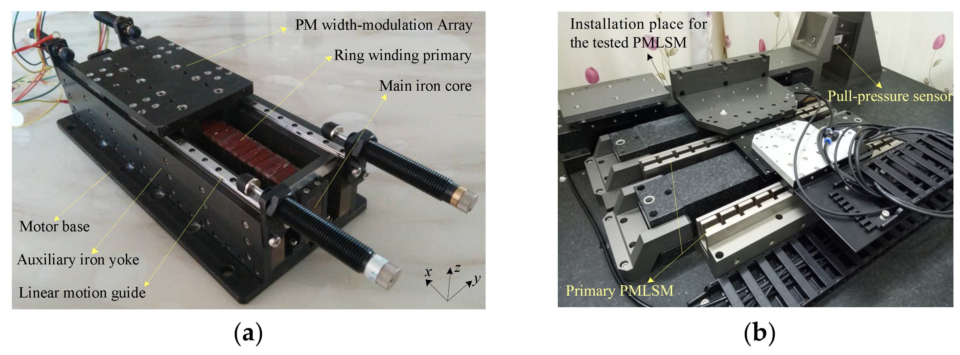
Based on the above analysis, a prototype of double-sided PMLSM with the PM-width modulation array is processed, shown in Figure 11.
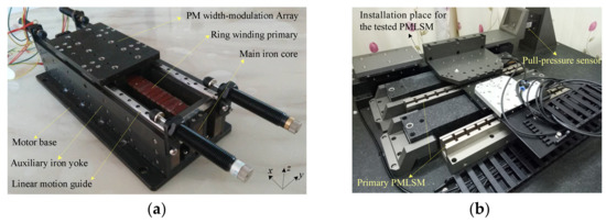
Figure 11.
Prototype: (a) motor, (b) test platform.
This prototype employs a carrier ratio s of 9 and a pole pitch of 24 mm due to the experimental condition limitations. A design scheme according to Array II is used because its carrier ratio s is 9. A universal driver was used to drive the prototype, ironless double-sided PMLSMs were employed to provide a matching constant load for the prototype. The prototype ran at a constant speed and a pull-pressure sensor was set between the mover of the prototype and the moving part of the ironless double-sided PMLSMs. The dynamic thrust of the prototype was obtained by the pull-pressure sensor. The main parameters of the prototype are listed in Table 7.
Table 7.
Main parameters of the prototype.
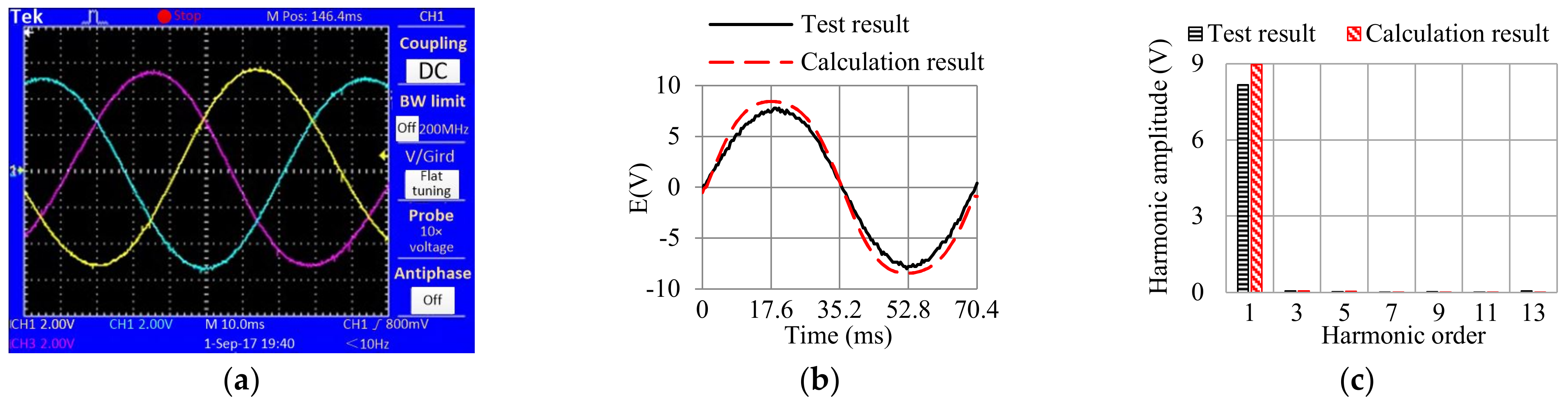
Figure 12 provides the waveforms of Back Electromotive Forces (EMFs) of the prototype in Figure 11, the test speed was 0.68 m/s.

Figure 12.
Back EMF of the prototype: (a) tested waveforms of three-phase Back EMFs, (b) waveform comparison of the test result and the calculation result, (c) harmonic contents of the test result and the calculation result.
According to Figure 12a, the tested Back EMFs have a feature of three-phase symmetry in the electrical degree, the amplitudes of the three waves are essentially the same, consistent with the theory of PMLSM. The waveforms of the test result and the calculation result of the Back EMF are compared in Figure 12b. Figure 12c provides the comparison of their harmonic contents, the data exhibit a great sinusoidal feature of the Back EMF. The transient thrust features of the prototype are tested and exhibited in Figure 13.

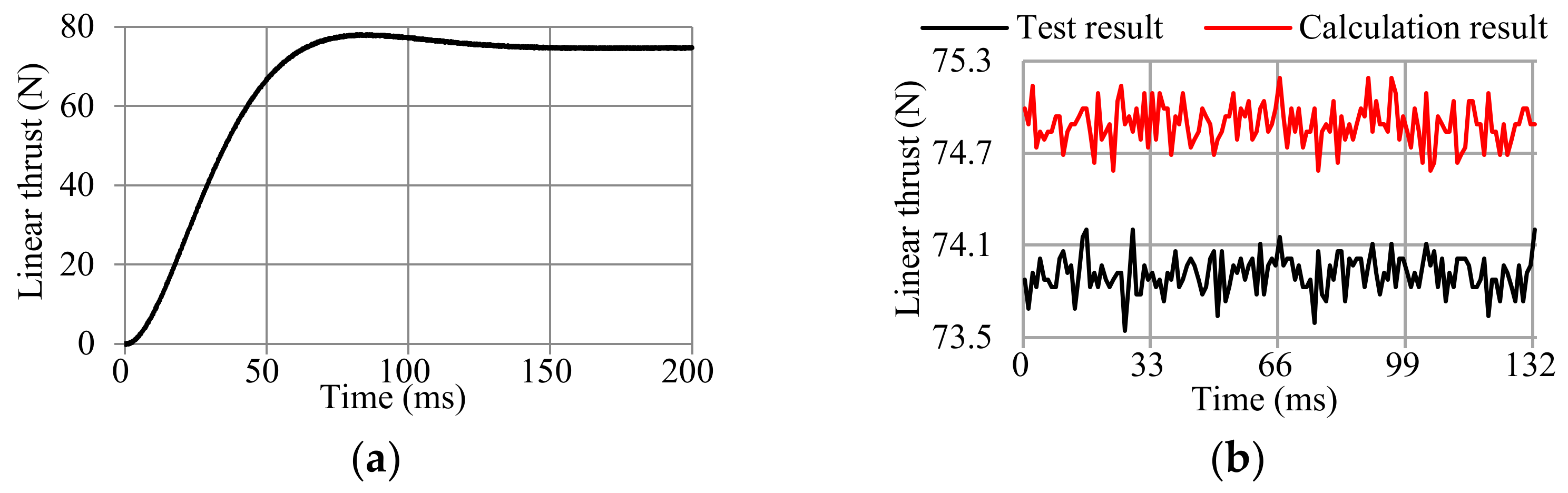
Figure 13.
Transient thrust features: (a) thrust step response, (b) stable thrust.
Three-phase symmetry alternating currents with an effective value of 3.5 A are provided for the armatures of the prototype, when the time is 0 ms. The loads of the measured prototype are provided by an electromagnetic eddy current damper. The measured transient time is 99.16 ms. For the stable thrust of the prototype, the calculation results of the average thrust and the thrust ripple are 74.89 N and 0.6037 N, the test results of the average thrust and the thrust ripple are 73.91 N and 0.63 N, the errors both are lower than 5%. The test data agree well with the analytical calculation. Thus, the response time and the thrust stability of PMLSM with the PM width-modulation array can meet the demands of the industrial systems with high speed and high precision.
7. Conclusions
This paper provides the analysis and comparison of two PM width-modulation arrays. The MMF and the PM eddy current of the PM width-modulation array are studied. The electromagnetic models of Array I and Array II are achieved and their properties are assessed by FEM method. The performances of two arrays are compared to obtain their respective application scopes. From these results, it can be concluded that the PM width-modulation array has advantages in the high-speed and high-precision PMLSMs. Based on the analysis, a prototype is manufactured, experimental data indicate the analysis results. The following are some of the inferences from the analysis and experiment results:
- (1)
- Compared to PMLSM with conventional non-salient secondary, the PM eddy current loss of PMLSM with PM width-modulation array can be reduced by 33.40%;
- (2)
- Array I (the PM width-modulation array designed by the equal area method) has a clear advantage on the FC amplitude of the magnetic flux density in the air gap, and has a higher average thrust;
- (3)
- For a low THD of the magnetic flux density in the air gap and a low thrust ripple, Array I has an advantage when 5 ≤ s ≤ 8 and Array II (the PM width-modulation array designed by the triangular modulation method) has an advantage when 9 ≤ s;
- (4)
- Array II should be chosen when the pole pitch of PMLSM is very large, because the carrier ratio s can be taken as a big value and it uses fewer PMs.
Author Contributions
M.L. contributed to this research article in the formal analysis, investigation, resources, data curation, and writing of the original draft. J.D. contributed to this research article for conceptualization and methodology. Z.Y. contributed to this research article for writing expression. All authors have read and agreed to the published version of the manuscript.
Funding
This research was funded by the National Natural Science Foundation of China under Grant 51907059 and the Natural Science Foundation of Hunan Province of China under Grant 2022JJ30138.
Conflicts of Interest
The authors declare no conflict of interest.
References
- Wen, T.; Xiang, B.; Wang, Z. Speed control of segmented PMLSM based on improved SMC and speed compensation model. Energies 2020, 13, 981. [Google Scholar] [CrossRef]
- Huang, X.; Ji, T.; Li, L.; Zhou, B.; Zhang, Z.; Gerada, D.; Gerada, C. Detent force, thrust, and normal force of the short-primary double-sided permanent magnet linear synchronous motor with slot-shift structure. IEEE Trans. Energy Convers. 2019, 34, 1411–1421. [Google Scholar] [CrossRef]
- Sun, X.; Shi, Z.; Chen, L. Internal model control for a bearingless permanent magnet synchronous motor based on inverse system method. IEEE Trans. Energy Convers. 2016, 31, 1539–1548. [Google Scholar] [CrossRef]
- Zhang, Z.; Luo, M.; Duan, J.A.; Kou, B. Design and modeling of a novel permanent magnet width modulation secondary for permanent magnet linear synchronous motor. IEEE Trans. Ind. Electron. 2021, 69, 2749–2758. [Google Scholar] [CrossRef]
- Luo, M.Z.; Zhang, Z.J.; Luo, C.Q. Research on two design approaches of permanent magnet width modulation secondary for permanent magnet linear synchronous motor. In Proceedings of the 2021 13th International Symposium on Linear Drives for Industry Applications, Wuhan, China, 1–3 July 2021. [Google Scholar]
- Du, G.; Xu, W.; Zhu, J.; Huang, N. Rotor stress analysis for high-speed permanent magnet machines considering assembly gap and temperature gradient. IEEE Trans. Energy Convers. 2019, 34, 2276–2285. [Google Scholar] [CrossRef]
- Wang, Y.; Ma, J.; Liu, C.; Lei, G.; Guo, Y.; Zhu, J. Reduction of magnet eddy current loss in PMSM by using partial magnet segment method. IEEE Trans. Magn. 2019, 55, 8105105. [Google Scholar] [CrossRef]
- Boduroglu, A.; Gulec, M.; Demir, Y.; Yolacan, E.; Aydin, M. A new asymmetric planar V-shaped magnet arrangement for a linear PM synchronous motor. IEEE Trans. Magn. 2019, 55, 8105905. [Google Scholar] [CrossRef]
- Zhu, X.; Yang, S.; Du, Y.; Xiang, Z.; Xu, L. Electromagnetic performance analysis and verification of a new flux-intensifying permanent magnet brushless motor with two-layer segmented permanent magnets. IEEE Trans. Magn. 2016, 52, 8204004. [Google Scholar] [CrossRef]
- Jing, L.; Luo, Z.; Qu, R.; Kong, W.; Gao, Y.; Huang, H.; Shah, M.R. Investigation of a surface PM machine with segmented-eccentric magnet poles. IEEE Trans. Appl. Supercond. 2018, 28, 5204305. [Google Scholar] [CrossRef]
- Jiao, Z.X.; Wang, T.Y.; Yan, L. Design of a tubular linear oscillating motor with a novel compound Halbach magnet array. IEEE/ASME Trans. Mechatron. 2017, 22, 498–508. [Google Scholar] [CrossRef]

Publisher’s Note: MDPI stays neutral with regard to jurisdictional claims in published maps and institutional affiliations. |
© 2022 by the authors. Licensee MDPI, Basel, Switzerland. This article is an open access article distributed under the terms and conditions of the Creative Commons Attribution (CC BY) license (https://creativecommons.org/licenses/by/4.0/).