Study Protocol

Influence of Guide Vane Slope on Axial-Flow Hydraulic Performance and Internal Flow Characteristics

1
Hefei Institute of Physical Science, Chinese Academy of Sciences, Hefei 230031, China
2
School of Mechanical Engineering, Hefei University of Technology, Hefei 230009, China
*
Authors to whom correspondence should be addressed.
Energies 2022, 15(17), 6103; https://doi.org/10.3390/en15176103
Submission received: 26 May 2022 / Revised: 18 July 2022 / Accepted: 17 August 2022 / Published: 23 August 2022

Abstract

:
To comprehensively study the influence of the guide vane inlet slope on the axial-flow pump, eight groups of axial-flow pumps with different guide vane inlet slopes are designed and studied in this paper. Four groups of schemes increase the relative slope at the rim of the guide vane blade, and the other four groups increase the relative slope at the hub. Numerical simulations have been verified experimentally and show good simulation accuracy. The numerical simulation results show that reducing the hub height of the guide vane can improve the head and efficiency of the axial-flow pump. Compared with the original scheme, the scheme H2/S2 is more stable in velocity and turbulent kinetic energy and has fewer vortices and low-speed areas at the guide vane. The scheme H3/S3 also exhibits excellent hydraulic performance and internal flow characteristics. It is recommended that when designing an axial-flow pump, the distance between the impeller and the guide vane at the hub can be appropriately larger than the distance between the impeller and the guide vane at the rim. This helps to reduce the velocity circulation at the outlet of the guide vane and improve the head and efficiency of the axial-flow pump.

1. Introduction

An axial-flow pump has the characteristics of a low head and high efficiency. Compared with the centrifugal pump, an axial-flow pump has the advantages of a simple structure, convenient installation, low noise and less heat production. With widespread application, guide vanes are installed behind the impeller to obtain stable flow and improve efficiency [1,2]. Moreover, the guide vane can make the velocity trajectory of impeller outlet gradually change from the original spiral shape into a straight one. The size of flow passage components and their matching relationship with each other directly affect the hydraulic performance of the axial-flow pump.
Lots of studies have been done on the improvement of the performance of axial-flow pumps by modifying guide vane parameters [3,4,5]. Horlock [6] found that the outlet angle of the guide vane affects the pressure change at the impeller by modifying the matching form between the pump inlet guide vane and the impeller. Properly staggering the guide vane can reduce the total pressure fluctuation at the impeller inlet. Combining numerical simulation and experimental research, Kim et al. [7] analyzed the influence of different inlet guide vane angles on the hydraulic performance of axial-flow pumps. The results showed that, under both design and non-design conditions, the changes in geometric parameters had a great impact on the hydraulic performance of axial-flow pumps. Based on three-dimensional computational fluid dynamics and DOE methods, Kim et al. [8] studied the influence of the interaction between the impeller and the guide vanes on the external characteristics of the axial-flow pump under different combinations of the number of impeller and guide vanes. Qian et al. [9] proposed a new adjustable guide vane (AGV) and obtained the adjustment formula of the AGV through theoretical analysis. At the same time, the flow of fluid in the axial-flow pump with the fixed guide vane and the adjustable guide vane was simulated. The results showed that adjustable guide vanes can significantly reduce hydraulic losses and improve the hydraulic performance of axial-flow pumps. Mosbahi et al. [10] analyzed the impact of the swept angle on the guide vane. Under design condition, the head and efficiency increase first and then decrease with the increase of the blade swept angle. When the blade swept angle was forward to 16°, the efficiency of the axial-flow pump reached its the maximum value. Xu et al. [11] divided the guide vane into three sections including inlet, middle section, and the outlet. By modifying the position of the inlet section, it was found that rotating the inlet section clockwise can expand the efficient operation range of the axial-flow pump. Yang et al. [12] added a set of inlet guide vanes with different angles and shapes at the impeller inlet and found that when the placement angle of the inlet guide vane increased to a positive angle, the flow efficiency decreased. When it reduced to a negative angle, the efficiency rose first and then decreased.
Many scholars have also studied the influence of guide vanes on the flow field in axial-flow pumps. According to the study of an axial-flow pump with a front guide vane, Li et al. [13] and Al-Obaidi [14] found that an appropriate number of guide vanes can help suppress axial pressure fluctuations and vibrations. Pu et al. [15] designed two sets of guide vanes according to the matching equation of the flow angle between the impeller and the guide vane. When the stagnation point at the entrance of the guide vane was offset, a low-speed vortex (LSV) was generated in the area from the mid-flow surface to the hub surface. Under the deep stall condition of an axial-flow pump, Kan et al. [16] used the Q criterion to study the position and evolution law of the core region of the vortex structure in the guide vane, which is mainly distributed at the outlet. Moreover, the distribution regions of its core are periodic. Besides, much research is being carried out on the internal energy loss and cavitation characteristics of axial-flow pumps with guide vanes [17,18,19,20].
A lot of research has been performed on the improvement of the guide vane of axial-flow pump at home and abroad, but few researchers have analyzed the angle between the space position of the impeller and the guide vane. To obtain the matching relationship between the impeller and the guide vane, this paper takes the small axial-flow pump as the research object. The effect of the angle between the guide impeller and the guide vane on the head and efficiency of the axial-flow pump is studied, and the operational stability of the axial-flow pump is discussed.

2. Materials and Methods

2.1. Geometric Models

The basic parameters of the axial-flow pump under design condition are as follows: the design flow rate Qd = 40 m3/h; the design head H = 0.5 m; the rotating speed n = 1000 r/min; the specific speed ns = 647. The basic parameters of the impeller are as follows: outlet diameter D = 112 mm; the hub ratio dh/D = 0.5; blade number Zh = 6. Additionally, the blade number of the guide vane is Zg = 7. To universalize the research model, the impeller design uses the 791 airfoils [21], and the height from the hub to the rim of the guide vane changes according to the height of the impeller. Figure 1 shows the computational area of the numerical simulation of the axial-flow pump, including four parts: the suction chamber, the impeller, the guide vane and the water outlet chamber.
The guide vanes with different slopes designed have the same number of vanes, and their inlet and outlet edges are all located on the same horizontal plane. As shown in Figure 2, the slope of the guide vane is obtained by modifying the height difference of the water inlet edge of the blade from the hub to the rim, while the outlet edge of the guide vane does not change. The original scheme of this paper is Δh0 = 4 mm. The first group of schemes is obtained by setting the height difference Δh1 as 0 mm, −4 mm, −8 mm and −12 mm when the height at the hub of the guide vane is the same as the original scheme. In addition, a series of slopes, namely kH, are acquired as 0, −k, −2k and −3k. Correspondingly, the first group of schemes are named as H0, H1, H2 and H3 respectively. The second group of schemes are gained by setting the height difference Δh2 as 0 mm, 4 mm, 8 mm and 12 mm, when the height at the rim of the guide vane is the same as the original scheme. Further, a series of slopes, namely ks, are acquired as 0, k, 2k and 3k. Correspondingly, the first group of schemes are named as S0, S1, S2 and S3 respectively, as shown in Figure 2. In the S1 scheme, the distance between the guide vane and the impeller is Δh, which is used as the original scheme for comparison with other schemes.
The influence of its slope on the hydraulic performance of the axial-flow pump is studied. The height difference of the impeller outlet from the hub to the rim is calculated as Δh [22]. The slope of the scheme is defined as follows:
k = Δ h r s r h
where, rs is the radius of the guide vane rim; rh is the radius of guide vane hub; Δh0 = 4 mm.

2.2. Model Setup

The ANSYS ICEM is used to generate the hexahedral structured grid of axial-flow pump domains, as shown in Figure 3. Due to the complex geometry of the impeller and guide vane of the axial-flow pump, the hub and rim adopt O-type structure topology. To increase the accuracy of the numerical simulation results, the mesh of the guide vane and impeller near the blade are refined. Since the grid size and quality have an important influence on the calculation results, the grid independence verification results of scheme S2 are given in Table 1. When the total grid number of the axial-flow pump increases to a certain value, the predicted head of the axial-flow pump gradually tends to stabilize. With the increase in the number of grids, the head difference and efficiency difference of the scheme 2 and scheme 3 do not exceed 0.2% and 0.7%, respectively. So, in order to improve the convergence speed, the total grid of scheme 2 is chosen in this paper.
The unsteady flow of an axial-flow pump is simulated by the ANSYS CFX. The turbulent flow model adopts the SST model, a hybrid, improved model of the k-ω model and the k-ε model, which is more accurate and effective in the calculation of the axial-flow pump flow domain. Here, pressure is chosen as the inlet boundary condition, and mass flow rate is adopted as the outlet boundary condition. All the walls are set as no-slip walls. The interface of the model is set to Frozen Rotor mode, where the connection angle is 360°, and the other interface types are set to None. Additionally, the interface between the rotor and the stator selects the frozen rotor condition in the steady calculation and selects the transient rotor-stator condition in the unsteady calculation. The residual convergence accuracy is 10−4, and the head-monitoring point is set. When the monitoring curve of the head tends to a straight line and the convergence accuracy is lower than 10−4, the calculation requirements are considered to be met, and the stable simulation is used as the initial calculation condition of the transient simulation. The time step is set as 1.67 × 10⁻⁴ s, which is described as a 1° rotation of the impeller. A calculation cycle is 360 steps, and a total of 10 cycles are calculated.

3. Results and Discussion

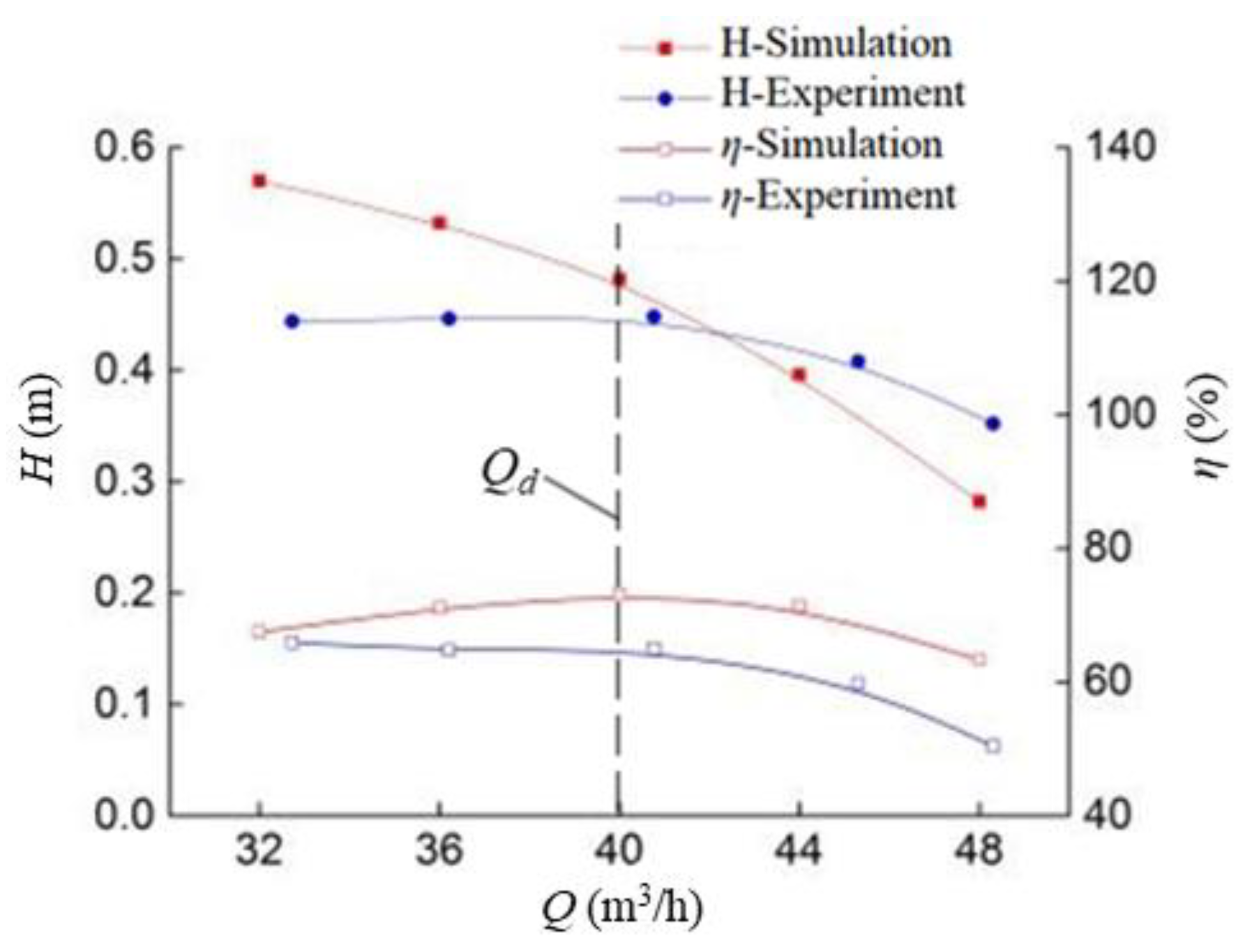
3.1. Experimental Verification

Figure 4 shows the experimental setup and composition, including power, measurement and hydraulic circulation devices. The power unit is composed of a motor, a model pump and an auxiliary pump. The measuring device consists of a torque meter, pressure sensor and flow meter. The circulation device is divided into pipes, water tanks and gate valves. The flow rate of the pump is measured by a Yokogawa AE215 flow sensor with an error of ± 0.5 % , and the measured pipe diameter is 80 mm. The pressure at the test pump outlet is measured by a Yokogawa EJA510A pressure gauge with an error of ± 0.075 % . The velocity head of the inlet and outlet is calculated by the velocity at a corresponding flow rate. The resistance loss of the pipeline is calculated in the same way when only auxiliary pump is working. The head of the test pump can be defined as:
H = P 2 P 1 ρ g + v 2 2 v 1 2 2 g + W
where H denotes the head of the test pump, W is the pipeline resistance. The torque of the experimental pump is measured with a JN338 torque sensor with an error of ± 0.2 % . The shaft power and efficiency of the pump are given by the formula:
P A = T A n 9550
P e = ρ g Q H
η = P e P A
where PA denotes the shaft power, Pe denotes the effective power, η denotes the efficiency.
Figure 5 shows the experimental and simulated performance curves of the axial-flow pump. The simulated value is greater than the experimental value under rated conditions. The difference is caused by external factors such as an unstable flow rate or reading error. The head of the axial-flow pump is very low. When calculating the head with the formula, the velocity head has a greater influence. Compared with the experimental value, the simulated head value is lower at low flow rates and higher at high flow rates. Some scholars have carried out experiments on miniature or low-head pumps, and the error is even higher than 10% [23,24]. Under the design operating conditions, the error between the simulated and experimental value of efficiency and head is kept within 3%. This indicates that the result of the simulation of the internal flow in the axial-flow pump is reliable.

3.2. External Characteristic Analysis

The head performance characteristics and efficiency of each scheme are analyzed under a flow rate varying from 0.8 Q to 1.2 Q. Figure 6 shows the external characteristic curve of each scheme, where S1 is the original scheme. The performance curve of the S1 scheme is plotted to compare with the H-scheme in Figure 6a. To present the difference of these schemes, the head and efficiency under design conditions of all schemes are summarized in Table 2.
Compared with the original scheme, the head and efficiency of the S2 scheme have increased by 0.7% and 0.1% respectively. The H1, H2 and S3 schemes have increased the head by 0.04%, 0.12% and 0.12% respectively. It is indicated that appropriately reducing the height of the guide vane at the hub will increase k, which can improve the head and efficiency of the axial-flow pump. The actual impeller is a spatial twisted blade combined with five cylindrical sections. When the radius of the cylindrical surface corresponding to the design parameters becomes smaller, the inlet angle of the guide vane and the height difference of the corresponding sections increase. This leads to the distance between the guide vane and the impeller near the hub being smaller than the design spacing. In the S2 scheme, the design spacing near the hub is larger than that at the rim. This results in uniform spacing between the guide vane and the impeller, and the water flowing out of the impeller can reach the guide vane at the same time. The collision of water flow, energy loss and velocity circulation of diversion outlet are reduced, and the head and efficiency are improved.

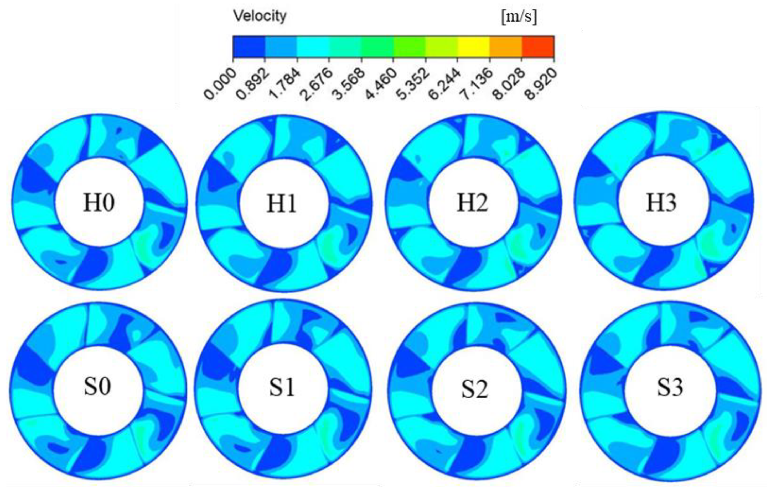
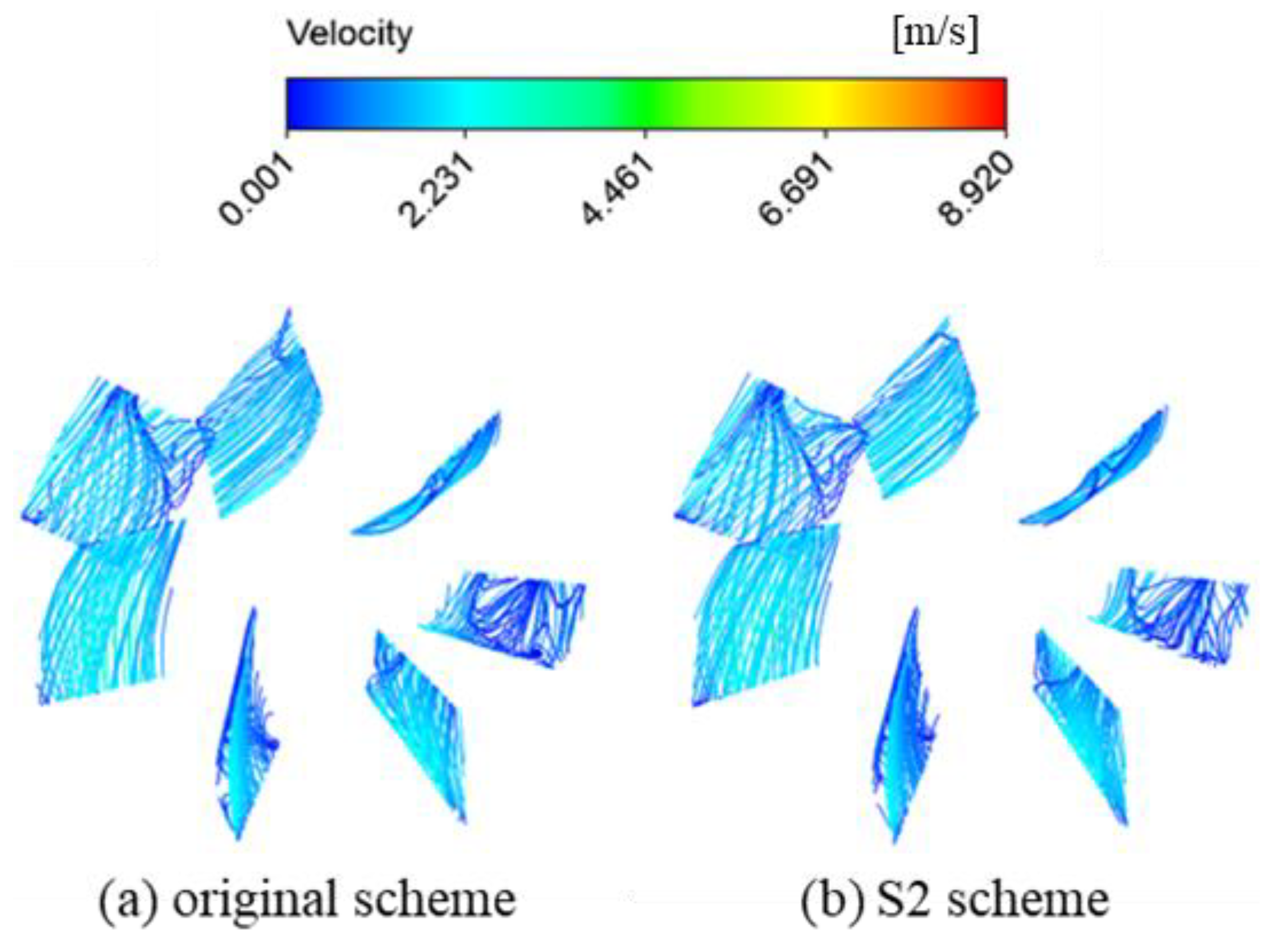
3.3. Analysis of Inflow Characteristics

Figure 7 gives the turbulent kinetic energy distribution at the outlet of the guide vane. The turbulent kinetic energy changes little in most areas of the guide vane outlets, but the suction surface near the guide vane changes greatly. In the H scheme, turbulent kinetic energy near almost all guide vanes is high, indicating that the S scheme is more stable than the H scheme. Like H1 to H3, the turbulent kinetic energy gradually decreases from S1 to S3, and the fluid is more stable. There is a small increase in turbulent kinetic energy from H0 to H1, and a similar phenomenon occurs in S1. In general, the output of the S2 scheme is more stable and the energy loss is the lowest.
Figure 8 shows the velocity distribution at the outlet of the guide vane. The low-speed range is mainly on the suction surface of the guide vane. The number of low-speed zones of H scheme is higher than that of S scheme, but the area of low-speed zone is smaller than that of S scheme. From H0 to H3 as well as from S0 to S3, the low-speed area decreases in size, and the speed gradually becomes stable. H3 and S3 have the fewest areas with 0 velocity and the H-scheme has more low-speed zones. This indicates that the velocity gradually becomes stable as the included angle increases. The comparison between S1 and S2 shows that the S2 has a more uniform velocity distribution. In addition, the difference between S2 and S3 is not obvious. S2 has a more uniform velocity distribution and the difference between S2 and S3 is not noticeable. Factoring in the turbulent kinetic energy results, S2 has the best speed and turbulence performance.
Figure 9 shows the streamline distribution of the guide vane surface for the S2 scheme and the original scheme. Figure 9a is similar to Figure 9b, indicating that the height of the guide vane at hub has a small impact on blade surface streamlining. Compared with the original scheme, the S2 scheme flow field is smoother. Therefore, increasing the slope of rim appropriately can reduce the vortex and energy loss at the guide vane.

4. Conclusions

In this paper, 8 optimization schemes of the axial-flow pump model are numerically simulated. The characteristics of hydraulic performance, flow velocity distribution and turbulent kinetic energy distribution under different guide vane inlet slopes are analyzed.
Both the numerical simulation results and the experimental results show that appropriately reducing the height of the guide vanes at the hub can improve the head and efficiency of the axial-flow pump. The turbulent kinetic energy in most areas at the outlet of the guide vane has a small change, but the change in the vicinity of the suction surface is relatively large. The low-speed areas are mainly concentrated on the suction surface of the guide vane. Compared with the original scheme, the scheme with a relative rim slope of 2k has more stable velocity and turbulent kinetic energy, and less velocity circulation at the guide vane. The scheme with a relative rim slope of 3k also shows better performance.
When designing an axial-flow pump, the axial relative distance between the impeller and the guide vane should be equal. However, to improve head and efficiency, the axial distance at the hub can be slightly larger than at the rim. This helps to improve fluid flow and hydraulic performance.

Author Contributions

Conceptualization, Y.L.; methodology, Q.L.; software, S.X.; validation, Y.L., Y.S. and Q.L.; formal analysis, Q.L.; investigation, Y.L.; resources, S.X.; data curation, S.X.; writing—original draft preparation, Y.S.; writing—review and editing, Y.L.; visualization, S.X.; supervision, Y.L.; project administration, Q.L.; funding acquisition, Y.L. and Q.L. All authors have read and agreed to the published version of the manuscript.

Funding

This research was funded by Hefei Municipal Natural Science Foundation [2021029], Major Science and Technology Projects of Anhui Province [202203f07020004] and [202203a05020026], President Fund of Hefei Institute of Physical Science, Chinese Academy of Sciences [YZJJ202203-CX].

Institutional Review Board Statement

The studies not involving humans or animals.

Informed Consent Statement

The study did not involve humans.

Data Availability Statement

No data was used for the research described in the article.

Conflicts of Interest

The authors declare no conflict of interest.

Nomenclature

kSlope of the guide vane [-]
ΔhHeight difference of the impeller outlet from the hub to the rim [mm]
rsRadius of the guide vane shroud [mm]
rhRadius of the guide vane hub [mm]
HPump head [m]
P1Total pressure of the pump inlet [Pa]
P2Total pressure of the pump outlet [Pa]
PAShaft power [W]
PeEffective power [W]
v1Velocity of the pump inlet [m/s]
v2Velocity of the pump outlet [m/s]
QFlow rate [m3/s]
QdDesign flow rate [m3/s]
gGravity [m/s2]
ηEfficiency [%]
ρDensity [kg/m3]
nRotating speed [r/min]
nsSpecific speed [rad·m3/4/s3/2]
TATorque [N·m]
Subscripts
1Pump inlet
2Pump outlet
sShroud
hHub

References

  1. Yang, F.; Zhao, H.R.; Liu, C. Improvement of the Efficiency of the Axial-Flow Pump at Part Loads due to Installing Outlet Guide Vanes Mechanism. Math. Probl. Eng. Theory Methods Appl. 2016, 2016 Pt 2, 6375314. [Google Scholar] [CrossRef]
  2. Zhang, H.; Shi, W.D.; Bin, C.; Zhang, Q.H.; Cao, W.D. Experimental study of flow field in interference area between impeller and guide vane of axial flow pump. J. Hydrodyn. Ser. B 2015, 26, 894–901. [Google Scholar] [CrossRef]
  3. Qian, Z.; Wang, Y.; Huai, W.; Lee, Y. Numerical simulation of water flow in an axial flow pump with adjustable guide vanes. J. Mech. Sci. Technol. 2010, 24, 971–976. [Google Scholar] [CrossRef]
  4. Yun, J.E. CFD Analysis for Optimization of Guide Vane of Axial-Flow Pump. Trans. Korean Soc. Mech. Eng. B 2016, 40, 519–525. [Google Scholar] [CrossRef]
  5. Park, H.C.; Kim, S.; Yoon, J.Y.; Choi, Y.S. A Numerical Study on the Performance Improvement of Guide Vanes in an Axial-flow Pump. KSFM J. Fluid Mach. 2012, 15, 58–63. [Google Scholar] [CrossRef]
  6. Horlock, J.H. The Use of Circumferentially Varying Stagger Guide Vanes in an Axial Flow Pump or Compressor. J. Turbomach. 1990, 112, 360–363. [Google Scholar] [CrossRef]
  7. Kim, Y.; Shim, H.S.; Kim, K.Y. Hydraulic Performance Characteristics of a Submersible Axial-Flow Pump with Different Angles of Inlet Guide Vane. J. Korean Soc. Fluid Mach. 2018, 21, 34–40. [Google Scholar]
  8. Kim, S.; Choi, Y.S.; Lee, K.Y.; Kim, J.H. Interaction of impeller and guide vane in a series-designed axial-flow pump. IOP Conf. 2014, 15, 2027. [Google Scholar] [CrossRef]
  9. Qian, Z.; Wang, F.; Guo, Z.; Lu, J. Performance evaluation of an axial-flow pump with adjustable guide vanes in turbine mode. Renew. Energy 2016, 99, 1146–1152. [Google Scholar] [CrossRef]
  10. Mosbahi, M.; Ayadi, A.; Chouaibi, Y.; Driss, Z.; Tucciarelli, T. Experimental and numerical investigation of the leading edge sweep angle effect on the performance of a delta blades hydrokinetic turbine. Renew. Energy 2020, 162, 1087–1103. [Google Scholar] [CrossRef]
  11. Xu, L.; Ji, D.; Shi, W.; Xu, B.; Lu, W.; Lu, L. Influence of Inlet Angle of Guide Vane on Hydraulic Performance of an Axial Flow Pump Based on CFD. Shock Vib. 2020, 2020, 8880789. [Google Scholar] [CrossRef]
  12. Yang, F.; Hu, W.Z.; Li, C.; Liu, C.; Jin, Y. Computational study on the performance improvement of axial-flow pump by inlet guide vanes at part loads. J. Mech. Sci. Technol. 2020, 34, 4905–4915. [Google Scholar] [CrossRef]
  13. Li, G.; Chen, E.; Yang, A.; Xie, Z.; Zhao, G. Effect of Guide Vanes on Flow and Vibroacoustic in an Axial-Flow Pump. Math. Probl. Eng. 2018, 2018 Pt 14, 3095890. [Google Scholar] [CrossRef]
  14. Al-Obaidi, A.R. Influence of guide vanes on the flow fields and performance of axial pump under unsteady flow conditions: Numerical study. J. Mech. Eng. Sci. 2020, 14, 6570–6593. [Google Scholar] [CrossRef]
  15. Pu, K.; Huang, B.; Miao, H.; Shi, P.; Wu, D. Quantitative analysis of energy loss and vibration performance in a circulating axial pump. Energy 2022, 243, 122753. [Google Scholar] [CrossRef]
  16. Kan, K.; Zheng, Y.; Chen, Y.; Xie, Z.; Yang, G.; Yang, C. Numerical study on the internal flow characteristics of an axial-flow pump under stall conditions. J. Mech. Sci. Technol. 2018, 32, 4683–4695. [Google Scholar] [CrossRef]
  17. Kaya, D. Experimental study on regaining the tangential velocity energy of axial flow pump. Energy Convers. Manag. 2003, 44, 1817–1829. [Google Scholar] [CrossRef]
  18. Liu, Y.; Han, Y.; Tan, L.; Wang, Y. Blade rotation angle on energy performance and tip leakage vortex in a mixed flow pump as turbine at pump mode. Energy 2020, 206, 118084. [Google Scholar] [CrossRef]
  19. Guo, Z.; Pan, J.; Qian, Z.; Ji, B. Experimental and numerical analysis of the unsteady influence of the inlet guide vanes on cavitation performance of an axial pump. Proc. Inst. Mech. Eng. Part C J. Mech. Eng. Sci. 2018, 233, 095440621880911. [Google Scholar] [CrossRef]
  20. Zhao, X.; Liu, T.; Huang, B.; Wang, G. Combined experimental and numerical analysis of cavitating flow characteristics in an axial flow waterjet pump. Ocean. Eng. 2020, 209, 107450. [Google Scholar] [CrossRef]
  21. Pengfei, M.A.; Wang, J.; Wang, H.F. Investigation of performances and flow characteristics of two bi-directional pumps with different airfoil blades. Sci. China (Technol. Sci.) 2018, 61, 1588–1599. [Google Scholar]
  22. Hong, G.; Lin, W.; Ye, F. An Investigation of the Flow and Global Performance in a Water-Jet Axial Flow Pump Based on CFD and Inverse Design Method. In Proceedings of the Asme Fluids Engineering Division Summer Meeting, Houston, TX, USA, 19–23 June 2005. [Google Scholar]
  23. Furukawa, A.; Watanabe, S.S. Performance test and flow measurement of contra-rotating axial flow pump. J. Therm. Sci. 2007, 16, 7–13. [Google Scholar] [CrossRef]
  24. Gao, H.; Lin, W.; Du, Z. Numerical flow and performance analysis of a water-jet axial flow pump. Ocean. Eng. 2008, 35, 1604–1614. [Google Scholar] [CrossRef]
Figure 1. 3D model of axial-flow pump.
Energies 15 06103 g001
Figure 2. The settings of the two schemes: (a) Plan H; (b) Plan S.
Energies 15 06103 g002
Figure 3. Hexahedral mesh.
Energies 15 06103 g003
Figure 4. Experimental setup: (a) left view; (b) top view. (1. Motor 2. Torque measuring instrument 3. Test model pump 4. Pressure gauge 5. Flow meter 6. Gate valve 7. Auxiliary pump 8. Gate valve 9. Water tank).
Energies 15 06103 g004
Figure 5. Comparison of numerical simulation and experimental results.
Energies 15 06103 g005
Figure 6. Variation in the trend of hydraulic performance under two types of schemes: (a) S scheme; (b) H scheme.
Energies 15 06103 g006
Figure 7. Turbulent kinetic energy distribution at the outlet of the guide vane.
Energies 15 06103 g007
Figure 8. Velocity distribution at the outlet of the guide vane.
Energies 15 06103 g008
Figure 9. Streamline distribution of the guide vane surface for the S2 scheme and the original scheme.
Energies 15 06103 g009
Table 1. Verification of grid independence.
SchemeGrid NumberHead/mEfficiency/%
1121,1580.48145572.1346
2478,5020.48510673.2363
31,092,2900.48630973.8755
Table 2. Hydraulic performance of different schemes under design conditions.
PerformanceH0H1H2H3S0S1S2S3
Head/m0.47860.48180.48220.48040.47920.48160.48510.4822
Efficiency/%72.6372.6872.7772.7873.1273.1573.2472.92
Publisher’s Note: MDPI stays neutral with regard to jurisdictional claims in published maps and institutional affiliations.

