Article

Study of Centrifugal Stiffening on the Free Vibrations and Dynamic Response of Offshore Wind Turbine Blades

Smart Infrastructure and Industry Research Group, Department of Engineering, Manchester Metropolitan University, Manchester M1 5GD, UK
*
Authors to whom correspondence should be addressed.
Energies 2022, 15(17), 6120; https://doi.org/10.3390/en15176120
Submission received: 28 July 2022 / Revised: 15 August 2022 / Accepted: 18 August 2022 / Published: 23 August 2022

Abstract

:
Due to their large and increasing size and the corrosive nature of salt water and high wind speeds, offshore wind turbines are required to be more robust, more rugged and more reliable than their onshore counterparts. The dynamic characteristics of the blade and its response to applied forces may be influenced dramatically by rotor rotational speed, which may even threaten the stability of the wind turbine. An accurate and computationally efficient structural dynamics model is essential for offshore wind turbines. A comprehensive model that takes the centrifugal stiffening effect into consideration could make rapid and accurate decisions with live data sensed from the structure. Moreover, this can enhance both the performance and reliability of wind turbines. When a rotating blade deflects in its plane of rotation or perpendicular to it, the centrifugal force exerts an inertia force that increases the natural frequencies and changes the mode shapes, leading to changes in the dynamic response of the blade. However, in the previous literature, studies of centrifugal stiffening are rarely found. This study investigates the influence of centrifugal stiffening on the free vibrations and dynamic response of offshore wind turbine blades. The National Renewable Energy Laboratory (NREL) 5 MW blade benchmark was considered to study the effect of angular speed in the flap-wise and edge-wise directions. The results demonstrate that the angular speed directly affects the modal features, which directly impacts the dynamic response. The results also show that the angular velocity effect in the flap-wise direction is more significant than its effect in the edge-wise direction.

1. Introduction

The statistics for the global investment rate in wind energy are a significant indicator of the rapidly increasing importance of this energy source worldwide [1]. Today, even in countries such as the UK, with its long shoreline, offshore wind turbines produce only 13 percent of the total UK electricity generated [2]. Thus, questions remain as to whether offshore sources can provide sufficiently rapid growth in wind energy across the world in time to meet demand.
Reliable design and maintenance are crucial for wind turbines. Autonomous health monitoring of wind turbines, particularly offshore ones, is highly desirable. It may be done via the digital twin framework in which computationally efficient models receive live and secure sensing data from the physical twin [3,4,5] Thus, autonomous decisions can be made, e.g., for performance optimisation or unscheduled maintenance [6,7].
The blade is one of the most frequent failing components in wind turbine systems [8]. It subjects to repetitive, sometimes extreme, aerodynamic loads. Aeroelasticity consists mainly of interactions between aerodynamics and structural dynamics, including the inertia forces. Fluid–structure interaction as a computational method has become integral to many engineering fields, including aerospace, the wind industry [9], civil engineering [10] and transportation [11]. The traditional definition of aeroelasticity assumes that the structure is inherently flexible, and the flow around the structure is unsteady due to the surface motion [9]. Finding natural frequencies and mode shapes is a fundamental step in analysing structural dynamics. Different codes [12] have adopted different techniques to produce computational models for the blade according to the specific structural details that need to be addressed. The blade is discretised into several rigid or flexible bodies, where the bodies are connected by a revolute joint. The FAST code [13] developed by the National Renewable Energy Laboratory (NREL) to simulate the dynamic response of a horizontal axis wind turbine (HAWT) uses the lumped mass technique to model the structure of the blade [13] The Bonus Horizontal Axis Wind Turbine Code (BHAWTC) that Siemens Wind Power developed uses finite elements to model the wind turbine blade as Timoshenko beam elements [14]. Timoshenko beam theory was also used in [15] to analyse the blade structure. The work in [16] used Rayleigh beam theory and incorporated the influence of the pitch and pre-cone angles on the dynamic characteristics of the HAWT blade in the flap-wise direction to determine the blade’s modal features. The influence of different blade parameters on the flap-wise vibrations was studied in [17], where the effects of such parameters on the dynamic characteristics of the NREL 5-MW wind turbine blades were investigated using different beam theories. The Euler–Bernoulli beam theory was considered in [18] for structural modelling.
A number of tools capable of performing aeroelastic analysis of wind turbine blades under various orders of accuracy have been addressed [13,18,19,20] These tools may be classified according to the methods adopted for the aerodynamic and structural dynamic analyses. Classical approaches [19] have used the blade element momentum theory (BEM), vortex and panel method and computational fluid dynamics for aerodynamic load calculations. BEM theory is an efficient tool for calculating aerodynamic loads, and satisfactory results can be obtained when reasonable sectional aerofoils data for lift and drag coefficients are available. An example is the well-known FAST (Fatigue, Aerodynamic, Structures, and Turbulence) programme developed by NREL to predict extreme and fatigue loads on HAWTs. The BLM method combines the blade element theory and momentum theory and solves the induction factor at each element iteratively.
Most studies reported in the literature focused on the interaction between structural and aerodynamic forces [13,18,19,20]. On the other hand, the interaction between inertial forces and structure has seldom been studied [21]. When a rotating blade deflects in its plane of rotation or perpendicular to it, the centrifugal force on each blade section exerts a normal force component which has the effect of stiffening the blade, changing the natural frequencies and mode shapes as a result. To the best of the authors’ knowledge, studies that include the centrifugal stiffening effect on the structural force are seldom seen. The work reported in [22] concludes that there is a noticeable dynamic stiffening effect on rotating blades, which had an even more significant influence on blades with greater flexibility.
When the beam is rotating, the natural frequencies increase. According to [23], the value of the fundamental frequency may be expressed using the Southwell formula as ω 1 2 = ω 1 , 0 2 + ϕ 1 Ω 2 , where ϕ is a geometric factor called the Southwell coefficient and ω 1 , 0 is the fundamental frequency for the non-rotating blade. The study [23] also suggested the value ϕ = 1.73 for the correction of the first flap-wise frequency, which is influenced mainly by the centrifugal force.
The centrifugal forces are always directed away from the centre of rotation. The change in the blade stiffness due to the centrifugal effect is due to an induced normal force which results from rotor motion. This force partially counteracts the centrifugal forces. The dynamic stiffening effect on the rotating blade influences the flexibility of the blades. As the rotational speed increases, the flap-wise natural frequencies increase significantly [22]. The fundamental flap-wise frequency has the largest rate of increase, a growth rate that decreases in the higher-order frequencies. Meanwhile, the edge-wise frequencies rarely increase as the coupling between the rotational motion of the rotor, and the edge-wise elastic deformation weakens the dynamic stiffening effect [22].
An analytical and numerical study on the centrifugal stiffening effect for a large rotating wind turbine blade based on the NREL blade was studied in [21]. Equivalently, the structural characteristics of a large wind turbine blade have been investigated using the rotating wedge beam model [21]. The study found that the centrifugal stiffening effect significantly impacts the blade’s first natural frequency. For example, the first frequency increases by 10% for the 5 MW NREL blade, while the centrifugal force had less impact on the other modal frequencies [21]. The work in [16] studied the effect of pitch and pre-cone angles with increasing rotational speed but did not quantify their effect on the dynamic response of the blade.
It is unlikely for every structural detail of composite blades in vibration analysis to be included. Each theory has its own theoretical assumptions and computational demands in the studies mentioned above. However, as previously pointed out, most of the approaches calculated the modal features at zero rotational speed, ignoring the effect of the centrifugal force on the structural and dynamic analysis. While previous studies rarely incorporated the centrifugal stiffening effect in the computational structural analysis, they all incorporated the angular speed as part of the aerodynamic procedure.
Several techniques may be used to calculate the aerodynamic loading of wind turbine blades. The study in [20] adopted geometrically exact beam theory to estimate the natural frequencies and corresponding mode shapes in the flap-wise and edge-wise directions and determine the deflection response in both directions. BEM theory was used in [20], and the same BEM theory was used to calculate the aerodynamic forces [18,24,25], while computational fluid dynamics was adopted in [26,27,28,29]
This study employs the Rayleigh beam theory, including the centrifugal stiffening effect, to determine its influence on natural frequencies, mode shapes and dynamic behaviour in to include the flap and edge directions. For the structural modelling and simulation, a finite element code was written using the specifications of the 5 MW NREL blade. The study subsequently incorporates the effects of the centrifugal force and examines its influence on the HAWT blade’s free vibration and forced response. Next, the dynamic response is calculated using the modal features extracted.
Due to the short computational time required and satisfactory results obtained, most researchers use approaches based on BEM theory by integrating the two-dimensional aerofoil aerodynamic loading along the blade’s different sections and calculating the normal and tangential forces. The BEM approach is also applied in this study for the aerodynamic loads. The structural analysis of the blade employs the Rayleigh beam theory with centrifugal stiffening to determine its effect on natural frequencies, mode shapes and dynamic responses in the flap-wise and edge-wise directions.

2. Methods in Modelling

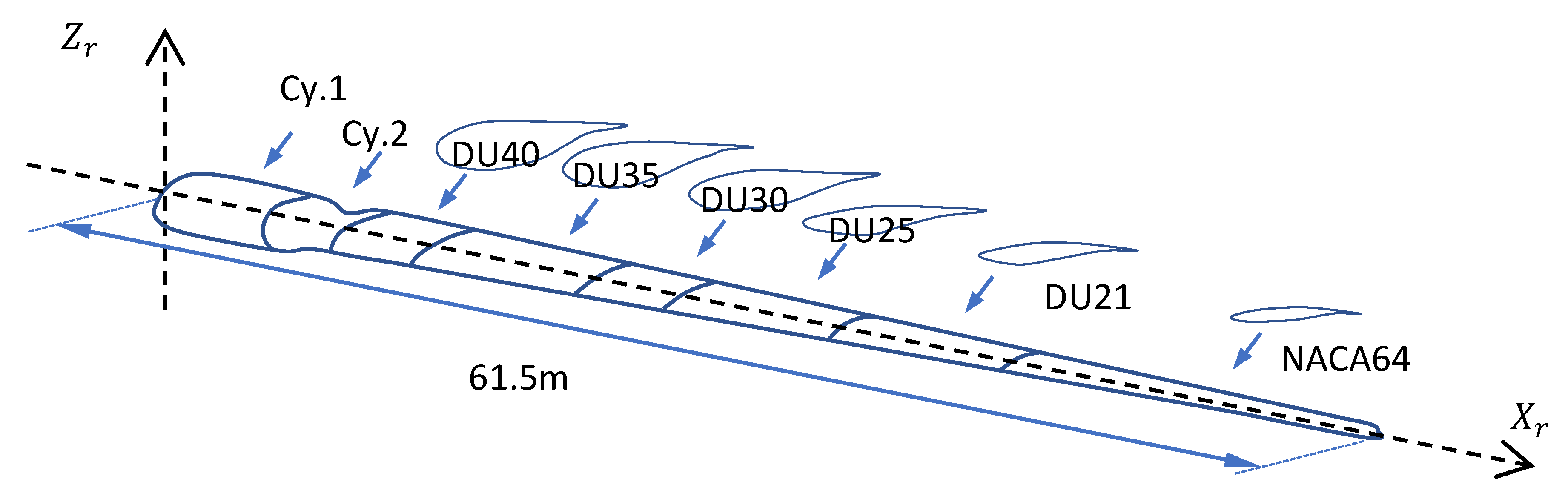
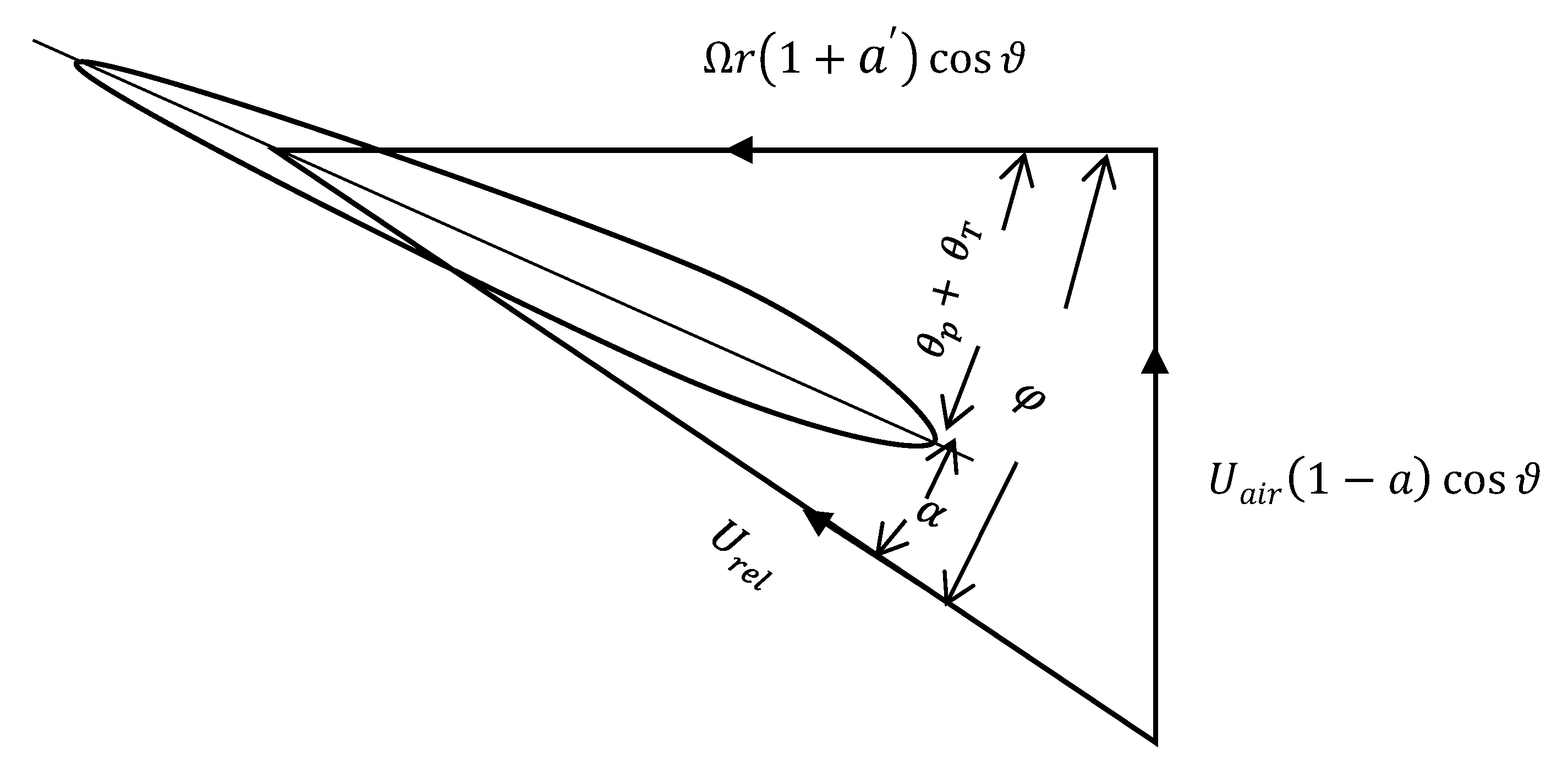
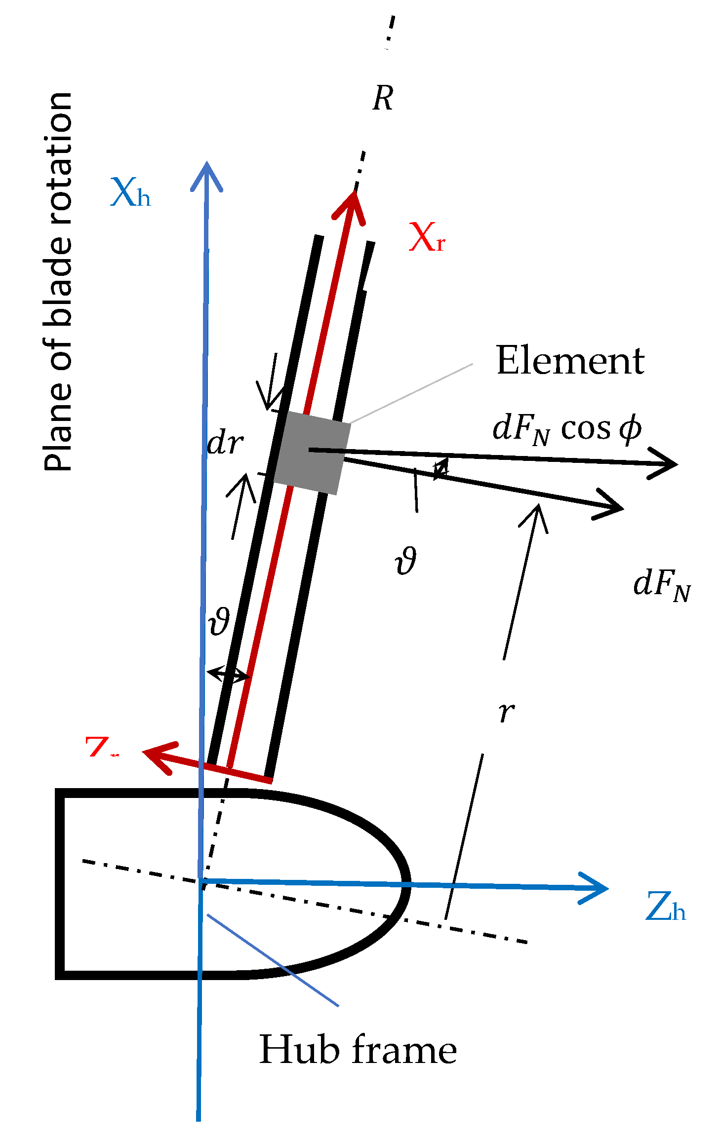
2.1. Aerodynamic Modelling

The forces on the blade element can be determined using the two-dimensional aerofoil theory, such as the lift and drag coefficients, and solving for the induction factors at each element iteratively. Consider the aerofoil section with chord c , and set the total pitch angle β as measured between the aerofoil zero lift line and the plane of the rotor disc. Both the chord length and the pitch angle vary along the blade span according to the aerofoil’s aerodynamic characteristics. In this study, the aerofoils of the 5 MW NREL blade adopted are shown in Figure 1. The blade rotates at a specific angular speed Ω under wind speed U a . The tangential velocity Ω r cos ϑ of the blade element combined with the tangential velocity of the wake Ω r a cos ϑ results in a net tangential flow velocity at each blade section of Ω r ( 1 + a ) cos ϑ . Figure 2 shows all the velocities relative to the blade section at radius r , and the radius r is the radial coordinate of the blade from the root.
From Figure 2, the angle of attack, α , is given by:
α = φ ( θ p + θ T )
where θ T   and   θ p are the twist angle of the blade element and the blade pitch angle, respectively. φ is the inflow angle and calculated as:
φ = arctan V a V r o t
where V a and V r o t   are the induced velocities in the rotor plane and are determined by means of axial and angular induction factors:
V a = U a i r 1 a cos ϑ
V r o t = Ω r 1 + a cos ϑ
The resultant relative velocity at the blade section is:
U r e l = U a i r 1 a cos ϑ 2 + r Ω 1 + a cos ϑ 2
where U a i r is the airflow velocity; r ,   Ω are the rotation radius of the blade element and angular velocity ; ϑ   is the angle of pre-cone; and a ,   a are the induction velocity factors and are found by iteration. The total pitch angle β is the sum of the element twist angle and the blade pitch angle at the blade section under consideration. The relative velocity U r e l acts at an angle φ to the plane of rotation. The rotational speed of the rotor affects the value of relative speed and the angle of attack at each blade section, as indicated in Equations (2)–(5).
In the blade element momentum theory, the force on a blade element is solely responsible for the change of momentum of the air that passes through the annulus swept by the element. The flow through each blade section at radius r is assumed to be a two-dimensional flow, as shown in Figure 3. According to [28], the normal aerodynamic force on a blade element is:
  f N = L cos α + β + D sin α + β cos ϑ
and the tangential aerodynamic force on a blade element is:
f T = L sin α + β D cos α + β cos ϑ
with
L = o .5 ρ a c C l U r e l 2
D = o .5 ρ a c C d U r e l 2
where f T in the tangential force to the circle swept by the rotor and f N is force normal to the plane of rotation along the blade’s different sections [4] D , L are the drag and lift forces at each blade element length, respectively; C l ,   C d   are the lift and drag coefficients, respectively; ρ a   , c are air density and chord length, respectively.
The following equations are convenient for determining values for axial and angular induction factors a and a [28]. The right-hand sides of the equations are evaluated using existing values of a and a , yielding simple equations for the next iteration.
a 1 a = σ r 4 sin φ C x σ r 4 sin 2 φ C y 2
a 1 + a = σ r   C y 4 sin φ cos φ
and
C y = C l sin φ C d cos φ
C x = C l cos φ + C d sin φ
σ r = B   c 2 π r   cos ϑ
where σ r is defined as the blade solidity, and φ is the inflow angle between the plane of rotation and the relative velocity.

2.2. Gravitational Load

This section proposes an edge-wise dynamic effect of the gravitational force on the HAWT blade. Due to the variation in the azimuth angle   θ , gravitational forces introduce an oscillating stiffness that changes with time and azimuth angle position. The gravitational force affects dynamic response in the edge-wise direction. The blade is assumed to start its motion from the upright position, where the azimuth angle equals zero. For the maximum effect of gravity on the load, the horizontal position of the blade is at an azimuth angle of 90 ° . Figure 4 shows the direction of the gravitational load and the gravitational load components acting on the blade in the edge-wise direction.

2.3. Blade Structural Model

This study employs the Rayleigh beam theory. The blade is considered to rotate at an angular velocity Ω . The blade undergoes flexural bending vibration in the edge- and flap-wise directions. The Lagrangian function may be written as [17]:
L   = Κ U + W
The total kinetic energy of the blade in the flap-wise direction is:
Κ = K 1 + Κ 2 + Κ 3
where the first term is due to the flexural bending, the second term is for the kinetic energy resulting from the rotary inertia and the third is the result of adding the effects of pre-cone and pitch angles [30].
The potential energy of the HAWT blade is:
U = U 1 + U 2
where the first term is the strain energy of the blade due to flexural bending and the second term is the potential energy due to the centrifugal and gravitational forces [17,30].
Applying Hamilton’s principle:
δ t 1 t 2 K U + W d t = 0
The governing Equation of motion for the Rayleigh theory in the flap-wise direction, including the control angles effect, may be expressed as [3,17]:
ρ A x 2 w x , t t 2 + 2 x 2   E I z z x 2 w x , t x 2 x T x , t w x , t x x ρ I z z x 3 w x , t x t 2 + Ω 2 x ρ I z z x w x , t x k x w x , t = f x , t
I = I x cos 2 ϑ and ϑ is the pre-cone angle, as shown in Figure 5.
T x , t = 1 2   x l ( ρ x A x Ω 2 R + x cos ϑ ρ x A x g cos θ cos ϑ ] d x
where T x , t is the axial tension due to the centrifugal force T c x and the gravitational force component T g x , t at a distance x from the centre of rotation, as shown in Figure 4.
The term k in Equation (19) is the result of adding the effects of pre-cone and pitch angles. It is due to the axis of rotation not being parallel to the flap-wise direction of the blade [16]:
k = 1 8 ρ A x Ω 2 2 cos 2 ϑ + cos 2 ϑ θ p + 2 cos 2 θ p + cos 2 ϑ + θ p 6
In the above equations, w x , t is the flap-wise bending displacement; ρ x ,   A x   represent the blade density and blade cross-sectional area at distance x relative to the blade span; I z z x is the blade moment of inertia due to the effect of pre-cone angle; L is the blade element length.
At stationary, the Equations (19)–(21) terms that include the angular velocity Ω will be equal to zero. However, when a rotating blade deflects either in its plane of rotation, as shown in Figure 4, or perpendicular to it, the centrifugal force on each blade element exerts an inertial force that has the effect of stiffening the blade and, as a result, affecting the blade’s modal features.
To study the centrifugal stiffening effect on the modal features in the edge-wise direction, the governing Equation of motion for the Rayleigh theory in the edge-wise direction, including the effect of the control angle, can be obtained in terms of the forced edge-wise (in-plane) direction of the non-uniform beam as shown in [17,30]:
ρ A x 2 v x , t   t 2 + 2 x 2 E I y y x 2 v x , t   x 2 x T x v x , t   x x ρ I y y x 3 v x , t   x t 2 + Ω 2 x ρ I y y x v x , t   x k x v x , t = f x , t
In the above Equation, v x , t is the edge-wise bending displacement. I y y x   is the blade moment of inertia in the edge-wise direction around y axis.

3. Blade Dynamic Response

The modal analysis technique can be applied to predict the forced response of a wind turbine blade subject to a given external force [28]. By establishing the modal model, the vibration response due to the aerodynamic forces in the flap-wise and edge-wise directions, gravitational loads and operational loads arising from actions of the control system can be computed. The response of a forced wind turbine blade depends primarily upon the blade’s dynamic characteristics, such as natural frequencies, mode shapes and the characteristics of the excitation force. The free vibration results obtained in Section 2.3 are used as input data to find the dynamic response under aerodynamic forces in the flap-wise and edge-wise directions of the wind turbine blade. The external force in the flap-wise direction is the normal aerodynamic force. The external force in the edge-wise direction is the tangential aerodynamic and gravitational forces, as indicated in Section 2.1 and Section 2.2. The decoupling process is addressed to form independent equations in terms of the principal coordinates and modal parameters such as natural frequencies, dissipating force and mode shapes.
When numerical methods are applied to solve the governing Equations (19) and (22), such as the finite element method [31], the general form of the matrix equation of a wind turbine blade subjected to different external forces may be expressed as:
M X ¨ + C X ˙ + K X = F 1 r , t F 2 r , t F 3 r , t . . . F n r , t
where   X = u i is defined as a sectional column matrix of linear or angular displacements ;   X ˙ = u ˙ i is a sectional column matrix of velocities and X ¨ = u ¨ i is a column matrix of accelerations; F is the force vector at nodes determined by the finite element method from the externally applied force and moment. The matrices M ,   C   and   K are the blade’s sectional mass, damping and stiffness matrices, respectively, and r is the blade radius at element i and i = 1 n .
Generally, for beam element, work performed by an external excitation force along a virtual displacement and work performed by an external excitation moment along a virtual slope may be expressed as:
δ W i = l 1 l 2 δ w , δ v T F a e r o x , t + δ w , δ v T M x , t d x    
where δ w i and δ w i are the virtual displacement and slope in the flap-wise direction and δ v i and δ v i in the edge-wise direction. In the finite element framework, the displacement field may be approximated by the nodal displacement U e and selected shape functions, e.g., Hermite functions H :
δ w δ v = H 1 x δ U e
δ w δ v = H 2 x δ U e
where the prime superscript indicates the spatial derivatives with respect to the longitudinal axis X or r; U e is the vector of nodal variables for a beam element [31], expressed as
U e T = u z 1 u y 1 θ z 1 θ y 1 u z 2 u y 2 θ z 2 θ y 2
In the study, the external loads in Equation (24) are the aerodynamic forces as defined in Equations (6) and (7). The external moments may be neglected.
The dynamic response of the HAWT blade to the fluctuating aerodynamic loads is investigated using modal analysis [28] as:
w X r , t = j = 1 i δ j t u z x j
v X r , t = j = 1 i q j t u y x j
where u z x and u y x are the j th mode shapes in the flap-wise and edge-wise directions, respectively, arbitrarily assumed to have a value of unity at the blade tip, and δ j t and q j t are the variation of displacement in both directions.

4. Effect of Rotation Speed on the Blade Modal Characteristics

The natural vibration frequencies corresponding to the flap-wise and edge-wise directions have been calculated. Figure 6 shows the calculation process for the extraction of the modal characteristics. The change of angular velocity from 0 to 25 RPM has been chosen to investigate its effect on the blade parameters. The first 10 natural frequencies and mode shapes are calculated, which may well cover the operational frequency range of the structure. It was found that including the value of angular velocity into the stiffness matrices considerably affected the first ten natural frequencies of the Rayleigh model; see Table 1.
The value of rotating speed used in Table 1 was 12.1 RPM as it was the design rotational speed value of the 5 MW blade and is the value usually considered when the aerodynamic forces are calculated. The other values were selected to determine the influence of centrifugal stiffness on the lower and higher natural frequencies.
The angular velocity directly affects the centrifugal force, rotary inertia, and, generally, the stiffness matrix. When the 5 MW blade rotates at 12.1 RPM, Table 1 shows that the fundamental natural frequency increases by 12% compared to zero rotational speed. Typically, centrifugal stiffening results in an increase of the first natural frequency in the out-of-plane direction. This effect reduces in the higher modes, as shown in the table, indicating that the influence of centrifugal stiffening becomes progressively less in the higher modes.
Table 2 shows the first natural frequencies of the same blade in the edge-wise direction. It shows that the fundamental natural frequency increases by 4.6% compared with the stationary value of rotational speed. However, as shown in the table, this effect reduces in the higher modes.
Additional information on mode shapes is presented in Figure 6. The first four translational and angular mode shapes are shown for the Rayleigh model at zero angular speed and angular speeds of 12.1 RPM and 25 RPM. A significant effect on the mode shapes can be seen for the rotational speed at 25 RPM. If the zero angular speed is taken, deviations occur for the first two modes at the mid-span in the case of translational and along the blade span in the case of angular modes. The effect is less for the third mode and insignificant for the fourth mode. As expected, the discrepancies are less for the angular velocity of 12.1 RPM than for 25 RPM for all modes, both angular and translational.

5. Effect of Rotation Speed on the Blade Dynamic Responses

As with any dynamic system, the response of a forced wind turbine blade depends primarily upon the blade’s dynamic characteristics [28]. The 5 MW blade used in this study was a three-bladed HAWT, developed by NREL, as shown in Figure 1 with a rotor diameter of 126 m and pre-cone angle of 2.5 ° . The aerodynamic properties such as chord length, twist angle, the position of each section along the blade span and aerofoil type are listed in Table 3 [13] for a rated output power of 5 MW, with a rotational speed 12.1 RPM in a wind of speed 11.4 m/s.
The design rotational speed value of 5 MW NREL blade of 12.1 RPM was selected as a benchmark to determine the natural frequencies and corresponding mode shapes. Then, a comparison was made against zero rotational speed to find the effect of including the design rotational speed on the value of the free vibration and its influence on the dynamic response. Note that the aerodynamic loads were calculated at the value of 12.1 RPM.
The specifications of the 5 MW NREL were introduced as input parameters. Each wind turbine blade was divided into 17 elements, and each element coincided with a particular aerofoil shape. The flowchart of the free vibration analysis is shown in Figure 7, while the forced vibration computational procedure is shown in Figure 8. At each time step, blade aerofoil, velocities and twist deformation of each blade element were delivered from the structural model to the aerodynamic model. At each blade section, the angle of relative speed and the angle of attack was calculated. Free vibration analysis was formulated at angular speeds of 12.1 RPM and 0 RPM to extract the modal parameters and allow a comparison between them. Aerodynamic loads are determined at each element and applied as an external distributed force for each model.
Table 4 shows the first five natural frequencies in the flap-wise and edge-wise directions. Column 2 represents the frequencies obtained in this study by adopting the Rayleigh theory at an angular speed of 0 RPM, while column 3 represents the frequencies by the same theory at an angular speed of 12.1 RPM. The first frequency value is in the flap-wise direction, where the frequency increases by 11.63% due to the effect of angular speed. The second value represents the frequency in the edge-wise direction where the effect of angular speed is less to be 4.40%. The third value represents the second frequency in the flap-wise direction. The impact of angular speed decreases in this mode by 4.44% compared to 0 RPM. The fourth value represents the second frequency in the edge-wise direction. The effect of angular speed becomes less to be more by 2.88%. As the effect of angular speed becomes less in the higher modes, the last frequency value by adding the angular speed is more by 1.96%. Columns 4 and 5 represent the frequencies from [13], where the B-modes and FAST codes are adopted to find the frequencies at angular speed = 0 RPM. Columns 6 and 7 represent the frequencies values from [20,32], respectively, at angular speed = 0 RPM. All the frequencies obtained at angular speed 0 RPM are close to those obtained by [13,20,32], which indicates that, as would be expected, having no centrifugal force on a stationary blade leads to much the same natural frequencies.
Table 5 shows additional results from previous publications regarding tip blade deflection due to the flap-wise (out-of-plane) and edge-wise (in-plane) vibrations. In Table 5, row 1 represents Li et al. [20], where a geometrically exact beam model and BEM theory were used to obtain the blade deformation in the flap-wise and edge-wise directions. In the same manner, row 2 represents the results of Sabale and Gopal [25], where BEM-EBM were used, while row 3 represents the results obtained from [13], where the B-Mods and FAST software developed by NREL were used. Row 4 represents the data obtained from [29] using a CFD flow solver and blade elastic deformation; row 5 represents the results obtained from Ponta et al. [15], where the generalised Timoshenko beam theory was adopted to model the wind turbine blade. Row 6 represents the results of Sabale and Gopal [25], where BEM-EBM were used, while row 7 presents the results from [32], calculated using the commercial software ABAQUS. Bernoulli beam theory was used to obtain the results in [18], as shown in row 8.
In Table 5, the results between rows 1 and 8 are compared with the present study at a rotational speed of 0 RPM. The BEM theory is used to calculate the aerodynamic loads. It was found that the results obtained from the present study agree with [13], where B-Mods and FAST software were used. Moreover, the flap-wise deflection agrees with reference [32], where the results were calculated using the FE commercial software ABAQUS, although the edge-wise deflection was significantly larger. The geometrically exact beam method was adopted in [20,24,32] for the structural analysis, and some differences can be noticed in the results. [15] adopted the Timoshenko beam theory to find the governing Equation, but it can be seen that the flap-wise deformation is small compared with other results. In comparison, the free vibration results in work [18] were obtained from applying the Bernoulli theory, which showed relatively large deflection values in both directions.
Row 9 shows the comparable results obtained in the present work with a rotational speed of 0 RPM. Row 10, however, presents the results obtained in this study for a rotational speed of 12.1 RPM, in both the flap-wise and edge-wise directions. We see the considerable impact of including the angular velocity when calculating the modal parameters and that its effect on the dynamic response is more significant in the flap-wise direction.
The distribution of dynamic displacement response in the edge-wise direction along the blade span is shown in Figure 9. The figure shows a comparison between the results obtained by the present study in the case of zero angular velocity and 12 RPM, and those obtained using commercial software such as BEM-ABAQUS [32], CFD-CSD [29] (CFD, computational fluid dynamics model, and CSD, computational structural dynamics model) and the results reported in [20]. The deflection in the flap-wise direction along the blade span due to the aerodynamic loading is shown in Figure 10. For comparison, the figure also shows results reported in [20,29,32]. All the compared studies show some discrepancies in the dynamic response at some positions along the blade span. For example, in Figure 10, the value of dynamic response at the tip blade at an angular velocity of 12.1 RPM is 4.69 m, while the value at the same position when used the modal parameter extracted at zero angular velocity is 5.87 m. The effect of including the angular velocity to calculate the model features has a direct impact on the dynamic response.

6. Conclusions

When a rotating blade deflects either in its plane of rotation or perpendicular to it, the resulting centrifugal forces increase the natural frequencies and change the modal shapes in ways that could affect the stability of the turbine. In this study, operational angular velocity was investigated to determine its effect on the structural dynamic features and the blade’s dynamic response in both the flap- and edge-wise directions.
  • The results obtained quantify how increasing the angular velocity of the blade impacts the natural frequencies and corresponding mode shapes. It was found that the centrifugal force effects for a speed of rotation of 12.1 RPM had a significant effect on the flap-wise deflection, where the dynamic deflection decreased by 21.5%. However, there was less impact in the edge-wise direction, where the dynamic deflection decreased by 8.2%. These results can be included in the analysis of turbine blades’ behaviour to increase offshore HAWTs’ reliability.
  • The results from the study demonstrate that the angular speed directly affects the modal features, which directly leads to a decrease in the dynamic response. Additionally, the results show that the angular velocity affects behaviour in the flap-wise direction more than in the edge-wise direction.
  • There are differences between the present deflection values and their reference counterparts. The differences can be seen in the flap-wise and edge-wise directions at a rotational speed of 0 RPM. In the edge-wise curve, as shown in Figure 9, the results of this study come with the linear distribution in the difference between the response at 0 RPM and 12.1 RPM. On the other hand, the distribution of the curve at 0 RPM of the mentioned references goes more significant than the present result at 0 RPM in the middle blade length. At the same time, some of them go to be even less than the present result at 12.1 RPM at the blade’s tip.
  • For the flap-wise results, the distribution of the curve at 0 RPM of the mentioned references is less than the present result at 0 RPM in the last blade quarter. Moreover, they are even less than the present result at 12.1 at the blade’s tip.
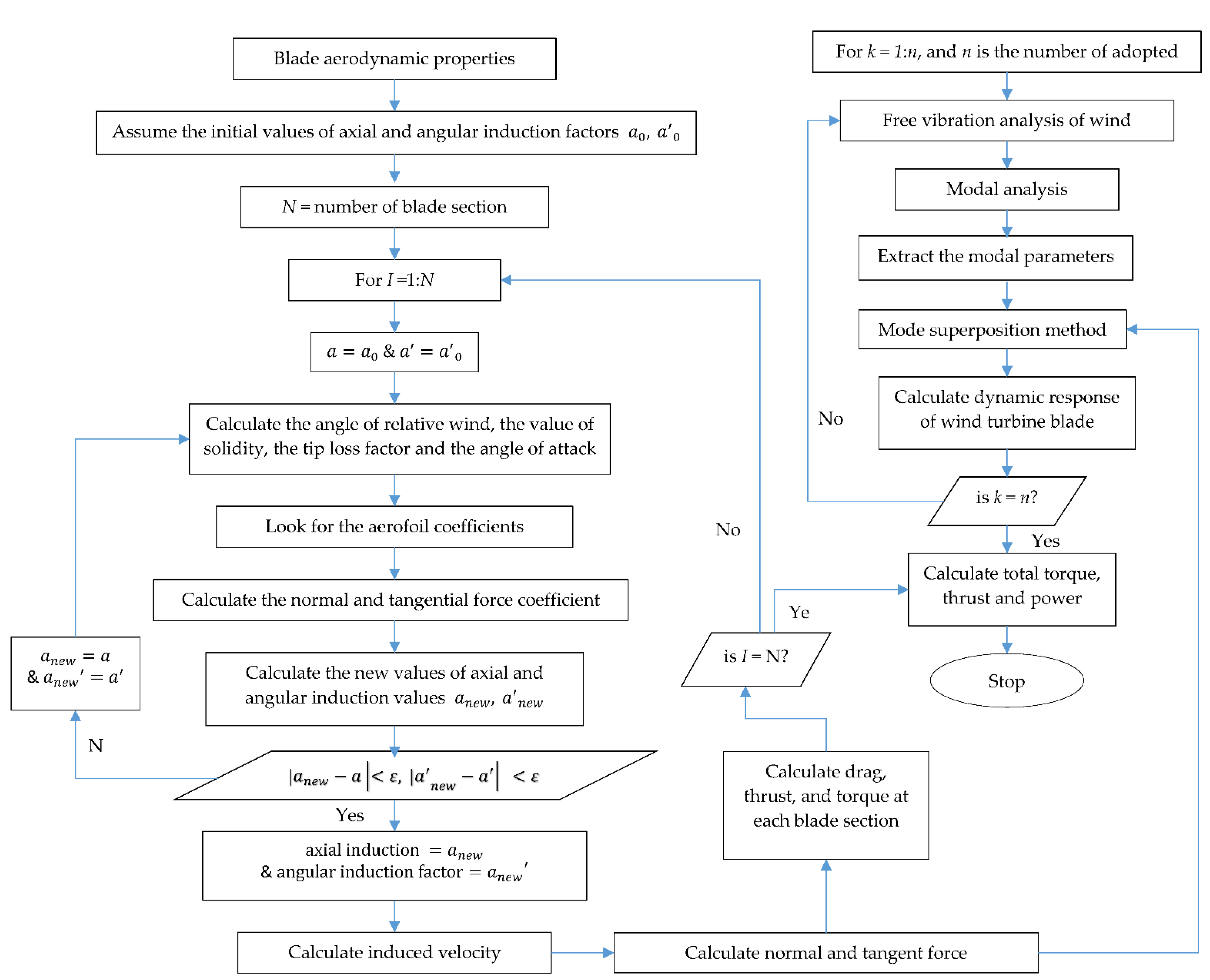
  • The dynamic response results of this study obtained the Rayleigh theory for structure and BEM for aerodynamic forces. Adding the influence of rotational speed at 12.1 RPM leads to decreasing the dynamic response. In conclusion, this may improve the accuracy of prediction for free vibration analysis and the deflection values as well.

Author Contributions

Writing—original draft preparation, A.A. (Amna Algolfat); writing—review and editing, W.W. and A.A. (Alhussein Albarbar); supervision, W.W. and A.A. (Alhussein Algolfat). All authors have read and agreed to the published version of the manuscript.

Funding

This research received no external funding.

Conflicts of Interest

The authors declare no conflict of interest.

Nomenclature

LBlade length (m)
DRotor diameter (m)
EModulus of elasticity (N/m2)
ABlade cross-sectional area (m2)
IBlade moment of inertia (m4)
Κ Kinetic energy (J)
U Potential energy (J)
W Work due to external distributed force (J)
w Flap-wise displacement (m)
f External force (N)
tTime (s)
RHub radius (m)
gGravitational acceleration (m/s2)
T Axial force due to centrifugal tension (N)
u Flap-wise deflection (m)
v Edge-wise deflection (m)
x Distance relative to the blade span ( m )
ρ The blade density ( kg / m 3   )
Ω Angular velocity of the blade ( r / min )
ϕ Southwell coefficient
θ p Pitch angle (deg)
θ T Twist angle (deg)
ϑ Pre-cone angle (deg)
α Angle of attack (deg)
β Total pitch angle (deg)
θ Azimuth position of the blade
ω Natural frequency(rad/s)
XhHub X-axis
YhHub Y-axis
GLocal gyroscopic matrix
mLocal mass matrix
kLocal stiffness matrix
f N Normal aerodynamic force (N)
f T Tangential aerodynamic force (N)
β Total pitch angle (rad)
a ,   a ' Induction velocity factors
L Lift force
D Drag force
ρ a Airflow density
C l Lift coefficient
C d Drag coefficient
C x Coefficient of sectional blade normal force
C y Coefficient of sectional blade parallel force
U a i r Airflow velocity (m/s)
F e x t Column matrix of the excitation forces and/or moments
c Chord length (m)
NRELNational Renewable Energy Laboratory
BEMBlade element momentum

References

  1. Gielen, D.; Gorini, R.; Wagner, N.; Leme, R.; Gutierrez, L.; Prakash, G.; Asmelash, E.; Janeiro, L.; Gallina, G.; Vale, G.; et al. Global Energy Transformation: A Roadmap to 2050; International Renewable Energy Agency (IRENA): Abu Dhabi, United Arab Emirates, 2019. [Google Scholar]
  2. Office for National Statistics. Wind Energy in the UK; Office for National Statistics: London, UK, 2021. [Google Scholar]
  3. Pimenta, F.; Pacheco, J.; Branco, C.M.; Teixeira, C.M.; Magalhães, F. Development of a digital twin of an onshore wind turbine using monitoring data. J. Phys. Conf. 2020, 1618, 022065. [Google Scholar] [CrossRef]
  4. Wang, M.; Wang, C.; Hnydiuk-Stefan, A.; Feng, S.; Atilla, I.; Li, Z. Recent progress on reliability analysis of offshore wind turbine support structures considering digital twin solutions. Ocean Eng. 2021, 232, 109168. [Google Scholar] [CrossRef]
  5. Sahu, K.; Alzahrani, F.A.; Srivastava, R.K.; Kumar, R. Evaluating the impact of prediction techniques: Software reliability perspective. Comput. Mater. Contin. 2021, 67, 1471–1488. [Google Scholar] [CrossRef]
  6. Attaallah, A.; Alsuhabi, H.; Shukla, S.; Kumar, R.; Gupta, B.K.; Khan, R.A. Analysing the Big Data Security Through a Unified Decision-Making Approach. Intell. Autom. Soft Comput. 2022, 32, 1071–1088. [Google Scholar] [CrossRef]
  7. Sivalingam, K.; Sepulveda, M.; Spring, M.; Davies, P. A review and methodology development for remaining useful life prediction of offshore fixed and floating wind turbine power converter with digital twin technology perspective. In Proceedings of the 2018 2nd International Conference on Green Energy and Applications (ICGEA), Singapore, 24–28 March 2018; pp. 197–204. [Google Scholar]
  8. Chou, J.S.; Chiu, C.K.; Huang, I.K.; Chi, K.N. Failure analysis of wind turbine blade under critical wind loads. Eng. Fail. Anal. 2013, 27, 99–118. [Google Scholar] [CrossRef]
  9. Hansen, M.O.; Sørensen, J.N.; Voutsinas, S.; Sørensen, N.; Madsen, H.A. State of the art in wind turbine aerodynamics and aeroelasticity. Prog. Aerosp. Sci. 2006, 42, 285–330. [Google Scholar] [CrossRef]
  10. Jafari, M.; Hou, F.; Abdelkefi, A. Wind-induced vibration of structural cables. Nonlinear Dyn. 2020, 100, 351–421. [Google Scholar] [CrossRef]
  11. Song, Y.; Zhang, M.; Øiseth, O.; Rønnquist, A. Wind deflection analysis of railway catenary under crosswind based on nonlinear finite element model and wind tunnel test. Mech. Mach. Theory 2022, 168, 104608. [Google Scholar] [CrossRef]
  12. Robertson, A.; Jonkman, J.; Vorpahl, F.; Popko, W.; Qvist, J.; Frøyd, L.; Chen, X.; Azcona, J.; Uzunoglu, E.; Guedes Soares, C.; et al. Offshore code comparison collaboration continuation within IEA wind task 30: Phase II results regarding a floating semisubmersible wind system. In Proceedings of the International Conference on Offshore Mechanics and Arctic Engineering, San Francisco, CA, USA, 8–13 June 2014; American Society of Mechanical Engineers: New York, NY, USA, 2014; Volume 45547, p. V09BT09A012. [Google Scholar]
  13. Jonkman, J.; Butterfield, S.; Musial, W.; Scott, G. Definition of a 5-MW Reference Wind Turbine for Offshore System Development; National Renewable Energy Lab. (NREL): Golden, CO, USA, 2009. [Google Scholar]
  14. Rosen, J.; Tietze-Stöckinger, I.; Rentz, O. Model-based analysis of effects from large-scale wind power production. Energy 2007, 32, 575–583. [Google Scholar] [CrossRef]
  15. Ponta, F.L.; Otero, A.D.; Lago, L.I.; Rajan, A. Effects of rotor deformation in wind-turbine performance: The dynamic rotor deformation blade element momentum model (DRD–BEM). Renew. Energy 2016, 92, 157–170. [Google Scholar] [CrossRef]
  16. Jokar, H.; Mahzoon, M.; Vatankhah, R. Dynamic modeling and free vibration analysis of horizontal axis wind turbine blades in the flap-wise direction. Renew. Energy 2020, 146, 1818–1832. [Google Scholar] [CrossRef]
  17. Algolfat, A.; Wang, W.; Albarbar, A. Comparison of beam theories for characterisation of a NREL wind turbine blade flap-wise vibration. Proc. Inst. Mech. Eng. Part A J. Power Energy 2022. [Google Scholar] [CrossRef]
  18. Rezaei, M.M.; Behzad, M.; Moradi, H.; Haddadpour, H. Modal-based damage identification for the nonlinear model of modern wind turbine blade. Renew. Energy 2016, 94, 391–409. [Google Scholar] [CrossRef]
  19. Liu, Y.; Xiao, Q.; Incecik, A.; Peyrard, C. Aeroelastic analysis of a floating offshore wind turbine in platform-induced surge motion using a fully coupled CFD-MBD method. Wind Energy 2019, 22, 1–20. [Google Scholar] [CrossRef]
  20. Li, Z.; Wen, B.; Dong, X.; Peng, Z.; Qu, Y.; Zhang, W. Aerodynamic and aeroelastic characteristics of flexible wind turbine blades under periodic unsteady inflows. J. Wind Eng. Ind. Aerodyn. 2020, 197, 104057. [Google Scholar] [CrossRef]
  21. Meng, H.; Jin, D.; Li, L.; Liu, Y. Analytical and numerical study on centrifugal stiffening effect for large rotating wind turbine blade based on NREL 5 MW and WindPACT 1.5 MW models. Renew. Energy 2022, 183, 321–329. [Google Scholar] [CrossRef]
  22. Xu, J.; Zhang, L.; Li, S.; Xu, J. The influence of rotation on natural frequencies of wind turbine blades with pre-bend. J. Renew. Sustain. Energy 2020, 12, 023303. [Google Scholar] [CrossRef]
  23. Putter, S.; Manor, H. Natural frequencies of radial rotating beams. J. Sound Vib. 1978, 56, 2–175. [Google Scholar] [CrossRef]
  24. Sabale, A.; Gopal, K.N. Nonlinear aeroelastic response of wind turbines using Simo-Vu-Quoc rods. Appl. Math. Model. 2019, 65, 696–716. [Google Scholar] [CrossRef]
  25. Sabale, A.K.; Gopal, N.K. Nonlinear aeroelastic analysis of large wind turbines under turbulent wind conditions. AIAA J. 2019, 57, 10–4416. [Google Scholar] [CrossRef]
  26. Li, Y.; Castro, A.M.; Sinokrot, T.; Prescott, W.; Carrica, P.M. Coupled multi-body dynamics and CFD for wind turbine simulation including explicit wind turbulence. Renew. Energy 2015, 76, 338–361. [Google Scholar] [CrossRef]
  27. Sayed, M.; Klein, L.; Lutz, T.; Krämer, E. The impact of the aerodynamic model fidelity on the aeroelastic response of a multi-megawatt wind turbine. Renew. Energy 2019, 140, 304–318. [Google Scholar] [CrossRef]
  28. Burton, T.; Jenkins, N.; Sharpe, D.; Bossanyi, E. Wind Energy Handbook; John Wiley & Sons: Hoboken, NJ, USA, 2011. [Google Scholar]
  29. Yu, D.O.; Kwon, O.J. Predicting wind turbine blade loads and aeroelastic response using a coupled CFD–CSD method. Renew. Energy 2014, 70, 184–196. [Google Scholar] [CrossRef]
  30. Algolfat, A.; Wang, W.; Albarbar, A. Comparison of Beam Theories for Simulating the Dynamic Response of a 5MW NREL Wind Turbine Blade Flap-wise and Edgewise Vibrations. J. Dyn. Monit. Diagn. 2022. [Google Scholar]
  31. Rao, S.S. The Finite Element Method in Engineering; Butterworth-Heinemann: Oxford, UK, 2017. [Google Scholar]
  32. Jeong, M.S.; Cha, M.C.; Kim, S.W.; Lee, I.; Kim, T. Effects of torsional degree of freedom, geometric nonlinearity, and gravity on aeroelastic behavior of large-scale horizontal axis wind turbine blades under varying wind speed conditions. J. Renew. Sustain. Energy 2014, 6, 023126. [Google Scholar] [CrossRef]
Figure 1. Schematic of the 5 MW NREL blade.
Energies 15 06120 g001
Figure 2. Blade element velocities.
Energies 15 06120 g002
Figure 3. Aerodynamic normal force at a blade element.
Energies 15 06120 g003
Figure 4. Gravitational load components acting on the blade in the edge-wise direction.
Energies 15 06120 g004
Figure 5. Blade root coordinate frames for 5 MW wind turbine blade.
Energies 15 06120 g005
Figure 6. Translational and angular mode shapes of NREL 5 MW HAWT blade at different angular velocities. (a) The first translational mode and (b) the first angular mode. (c) The second translational mode and (d) the second angular mode. (e) The third translational mode and (f) the third angular mode. (g) The fourth translational mode and (h) the fourth angular mode.
Energies 15 06120 g006
Figure 7. Flowchart of the natural frequencies and mode shape extraction procedure.
Energies 15 06120 g007
Figure 8. Forced vibration computational procedure.
Energies 15 06120 g008
Figure 9. Blade deflection in the edge-wise due to the aerodynamic loading; The two sets of results for the present work were calculated for angular speeds Ω = 0 RPM (solid line) and 12.1 RPM (black dashed line); compared with the yellow dotted line (data adapted from [20]), the green dash-dotted line (data adapted from [32] where BEM-ABAQUS was applied) and the red dashed line (data adapted from [29] where CFD-CSD was applied).
Energies 15 06120 g009
Figure 10. Blade deflection in the flap-wise due to the aerodynamic loading; The two sets of results for the present work were calculated for angular speeds Ω = 0 RPM (solid line) and 12.1 RPM (black dashed line); compared with the yellow dotted line (data adapted from [20]), the green dash-dotted line (data adapted from [32] where BEM-ABAQUS was applied) and the red dashed line (data adapted from [29] where CFD-CSD was applied).
Energies 15 06120 g010
Table 1. The first ten natural frequencies (Hz) variation in the flap-wise direction as a function of rotor speed Ω = 0   to   25   RPM ) of NREL 5 MW HAWT blade.
Rotational Speed (RPM)02.551012.1152025
Mode No.
10.68080.68470.69610.73990.76430.80700.89140.9881
21.98511.98912.00082.04712.07372.12192.22232.3448
34.54334.54714.55854.60394.63034.67854.78074.9087
48.13288.13668.14798.19328.21968.26808.37148.5022
512.674912.678512.689312.732612.757912.804312.903913.0305
618.031218.035118.045718.087818.112518.157718.255118.3793
724.214124.217524.227824.268924.293024.337224.432524.5542
831.323931.327331.337531.378331.402331.446331.541031.6624
939.565339.568639.578539.618139.641339.683939.775839.8934
1048.194548.198248.209548.254448.280748.329248.434048.5686
Table 2. The first ten natural frequencies (Hz) in the edge-wise direction as a function of rotor speed Ω = 0   to   25   RPM ) of NREL 5 MW HAWT blade.
Rotational Speed (RPM)02.551012.1152025
Mode No.
11.11291.11491.12101.14491.159521.18371.23581.2997
24.18084.18254.18764.20814.22084.24214.28924.3489
39.71489.71659.72179.74269.75559.77739.82569.8874
417.466617.468317.473517.494217.506917.528617.576617.6381
527.606427.608127.613127.633327.645727.666827.713727.7737
639.163839.165439.170439.190039.202239.222739.268539.3272
752.417752.419352.424252.443852.456052.476552.522252.5809
867.537967.539567.544467.563967.575967.596467.641967.7003
984.273684.275284.280084.299484.311484.331784.376984.4350
10102.6051102.6067102.6114102.6302102.6418102.6615102.7053102.7617
Table 3. 5 MW NREL wind turbine blade sections and aerofoils.
SectionPosition (m)Chord (m) Twist   ( ° ) Aerofoil
12.873.54213.308Cylinder 1
25.603.85413.308Cylinder 1
38.334.16713.308Cylinder 2
411.754.55713.308DU40_A17
515.854.65211.480DU35_A17
619.954.45810.162DU35_A17
724.054.2499.011DU30_A17
828.154.0077.795DU25_A17
932.253.7486.544DU21_A17
1036.353.5025.361DU21_A17
1140.453.2564.188NACA_64_618
1244.553.013.125NACA_64_618
1348.652.7642.319NACA_64_618
1452.752.5181.526NACA_64_618
1556.172.3130.863NACA_64_618
1658.902.0860.370NACA_64_618
1761.631.4190.106NACA_64_618
Table 4. Natural frequencies in the flap-wise and edge-wise directions of a single blade without aerodynamic force at angular speed Ω = 12.1 RPM for the present study and Ω = 0 RPM for the present study and for the data adapted from [13,20,32] (F = Flap, E = Edge).
Mode No.Rayleigh (Hz) at Ω = 0 RPM
Present Work
Rayleigh (Hz) at Ω = 12.1 RPM
Present Work
B-Modes Hz at
Ω = 0 RPM
[NREL]
FAST Hz at
Ω = 0 RPM
[NREL]
[20] (Hz) at
Ω = 0 RPM
[32] (Hz) at
Ω = 0 RPM
10.68 F0.764 F0.69 F0.68 F 0.67 F0.68 F
21.11 E1.16 E1.12 E1.10 E1.11 E1.10 E
31.98 F2.07 F2.00 F1.94 F1.92 F1.98 F
44.10 E4.22 E4.12 E4.00 E3.96 E3.99 E
54.54 F4.63 F4.69 F4.43 F4.43 F4.66 F
Table 5. Comparison of the dynamic response under nominal working conditions, in the present work, the modal parameters were calculated for angular speeds of 0 RPM and 12.1 RPM, while in all the reference results, the modal parameters were calculated for zero angular speed.
No.ReferenceFlap-Wise
Deflection (m)
Edge-Wise Deflection (m)
1Li, et al., 2020 [20]4.49−0.57
2Sabal & Gopal, 2019a [24]4.41−0.57
3Jonkman et al., 2009 [13]5.47−0.61
4Yu & Kwon, 2014 [29]4.72−0.63
5Ponta et al., 2016 [15]3.85−0.56
6Sabale & Gopal, 2019b [25]4.55−0.62
7Jeong et al., 2014 [32]4.83−0.75
8Rezaei et al., 2016 [18]8.35−1.85
9present work: angular speed 0 RPM5.83−0.66
10present work: angular speed 12.1 RPM4.70−0.61
Publisher’s Note: MDPI stays neutral with regard to jurisdictional claims in published maps and institutional affiliations.

