Analysis and Verification of Leakage Inductance Calculation in DAB Converters Based on High-Frequency Toroidal Transformers under Different Design Scenarios

 , , , and
Abstract
:1. Introduction
- A high-frequency toroidal transformer is developed using FEM instead of a shell-type or core-type for a dual active bridge (DAB) converter.
- Leakage inductance is a major factor in reducing the power transfer in the DAB converter, therefore leakage inductance as a function of frequency is studied under different scenarios and minimized leakage inductance is obtained.
- Other parameters, such as magnetic field lines, magnetic flux density and intensity are discussed and compared with the shell-type transformer. As a result, the best possible uniform parameters are obtained in the case of the toroidal transformer.
- A reduced leakage-inductance-based toroidal transformer is used in a DAB converter and the simulated results are validated with the help of an experimental prototype.
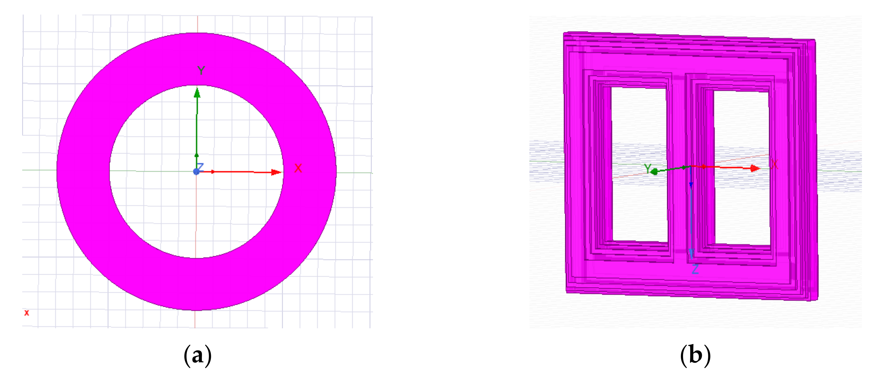
2. Design of a Toroidal Transformer Using ANSYS Maxwell
2.1. ANSYS-Electromagnetic
2.2. Core Selection
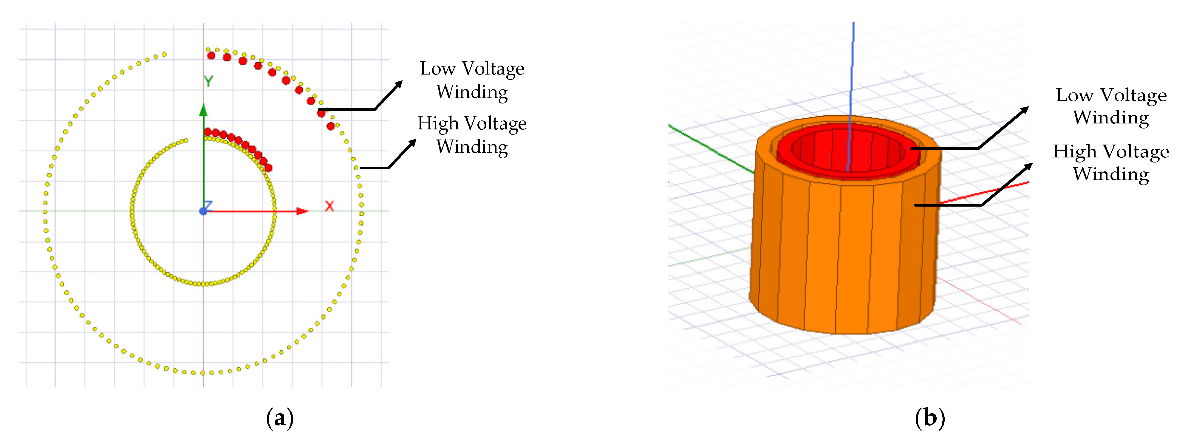
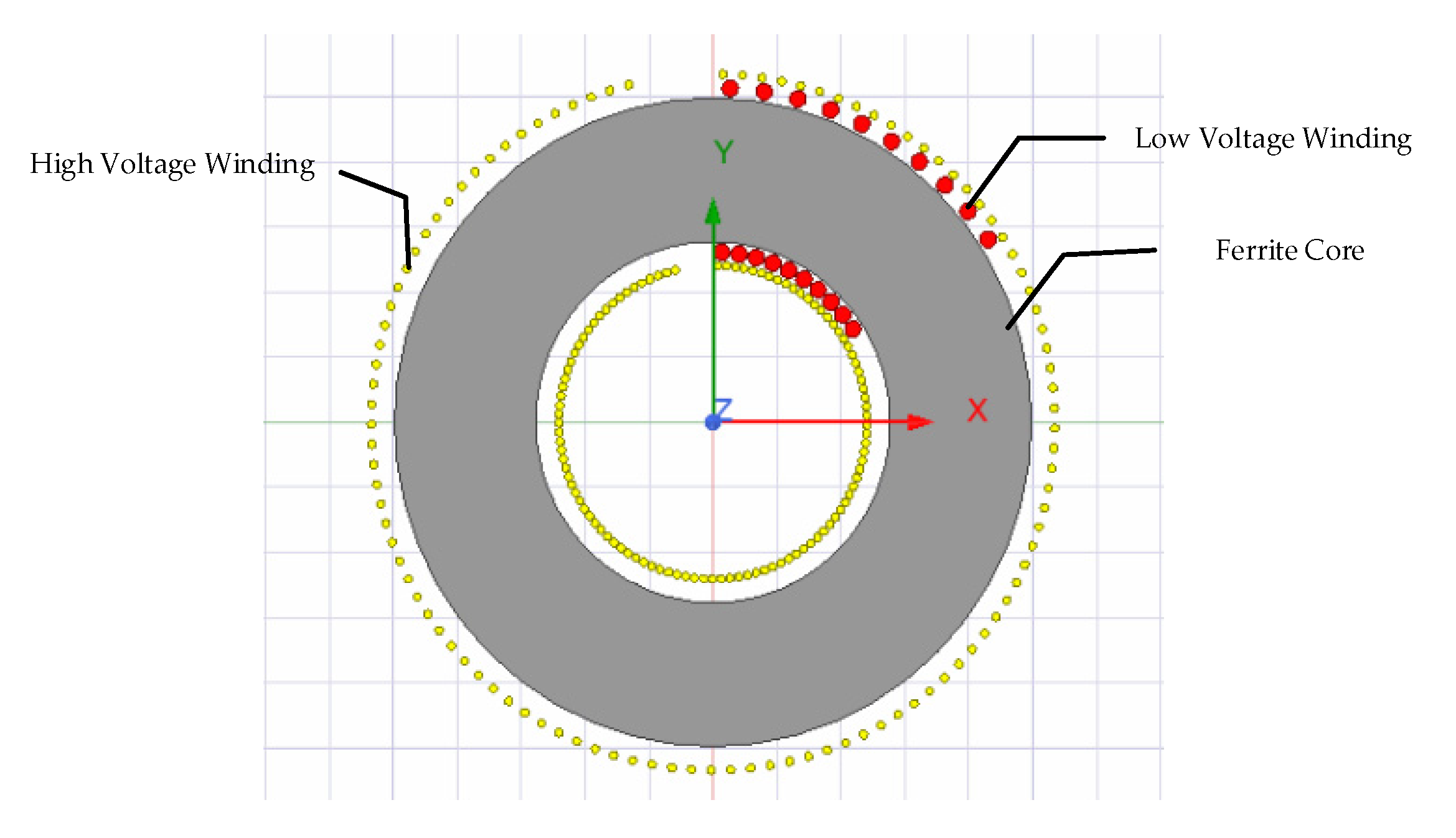
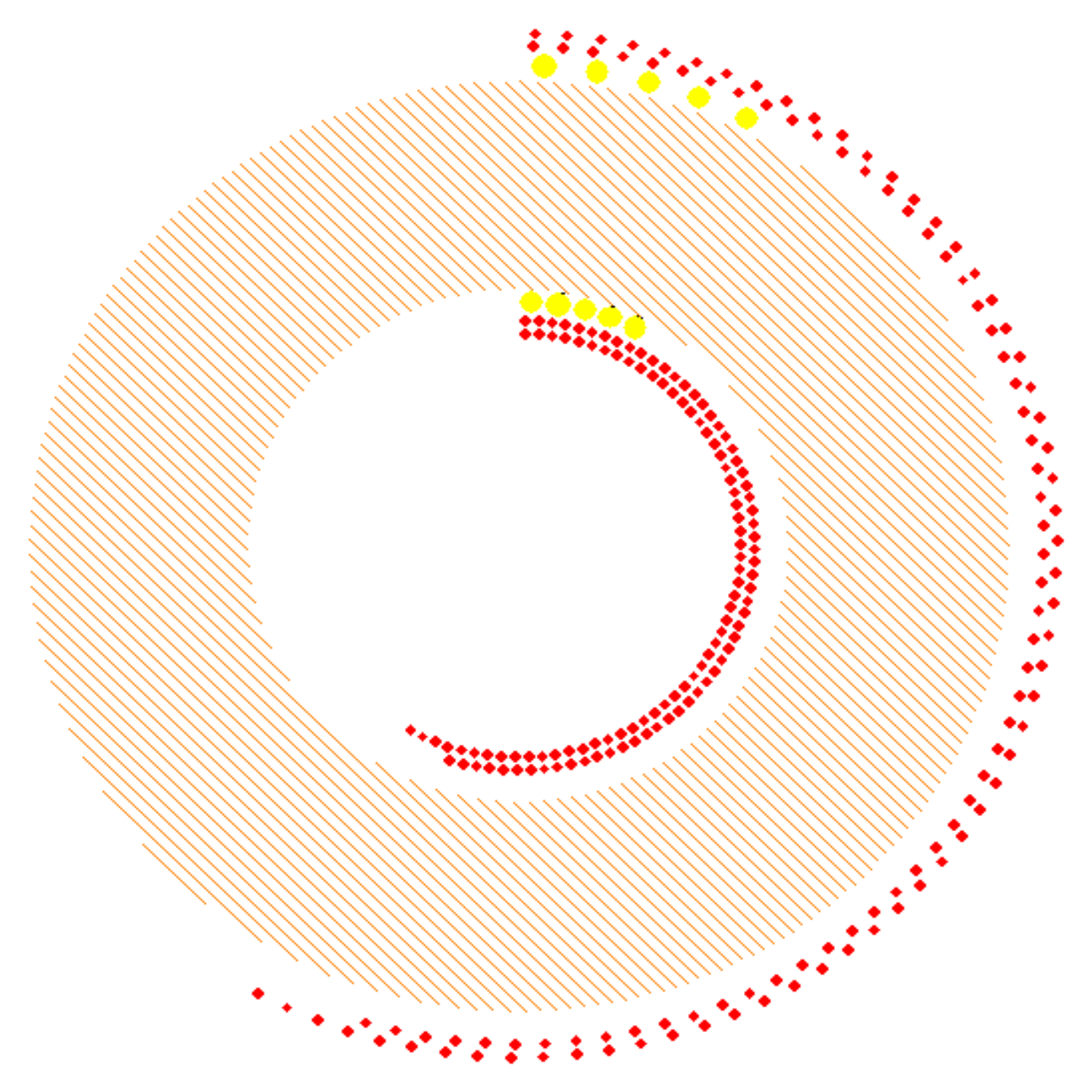
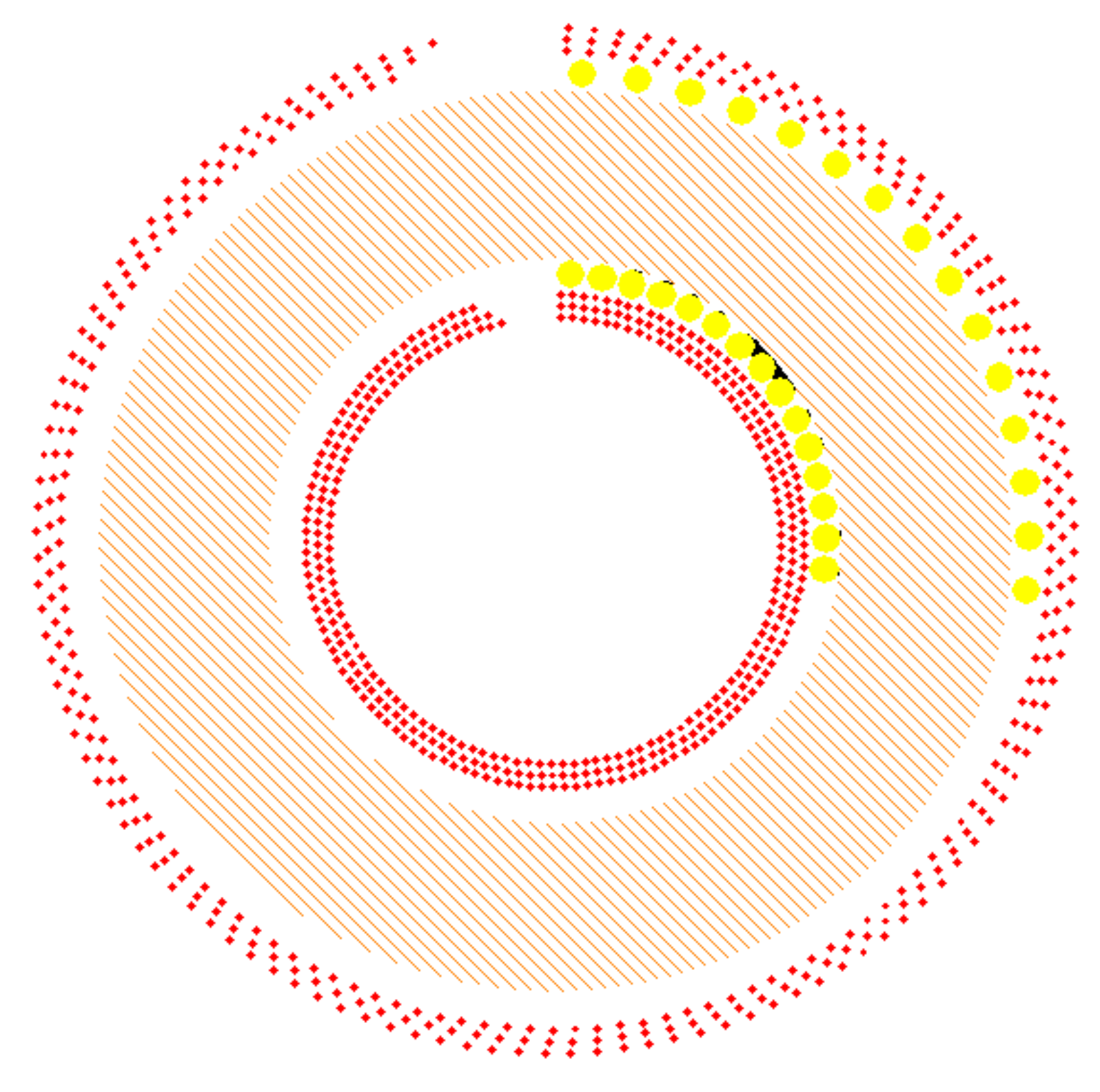
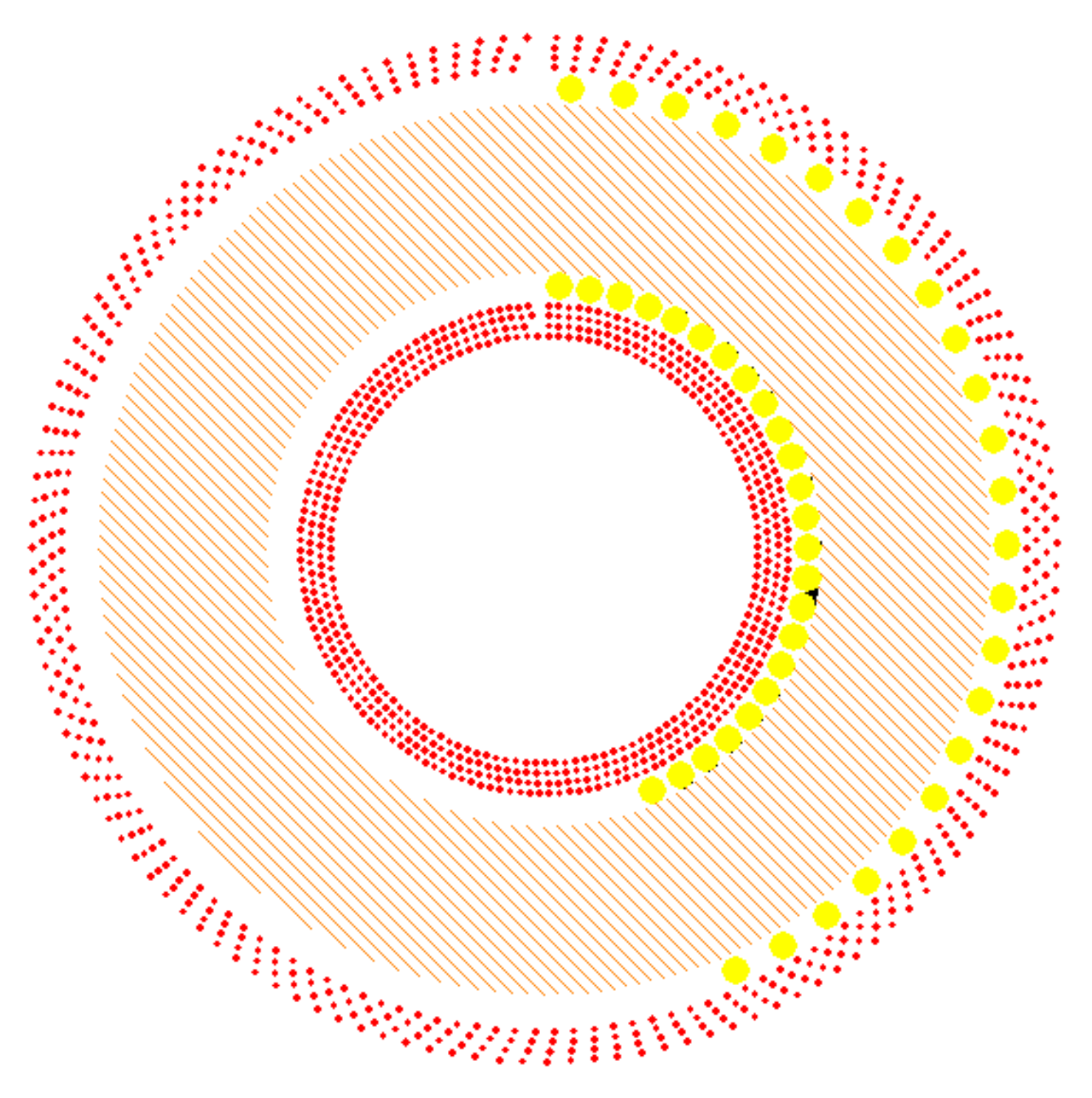
2.3. Design of Windings
3. ANSYS Maxwell Simulations of Toroidal Transformer
3.1. Parametric Analysis of Toroidal Core Transformer
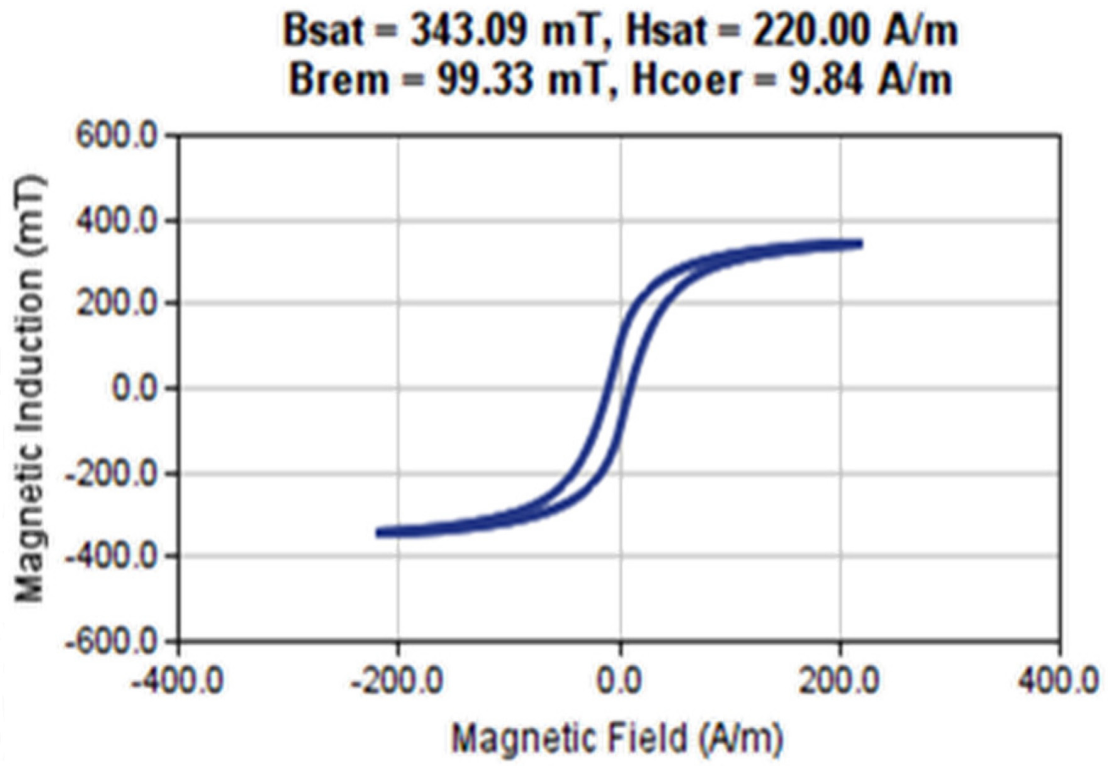
3.2. Material Determination of Cores and Coils
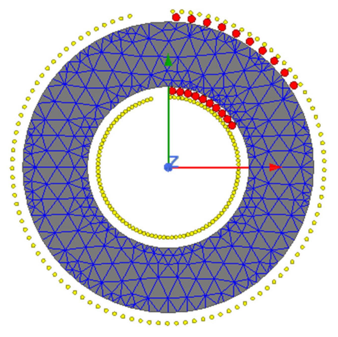
3.3. Mesh Configuration
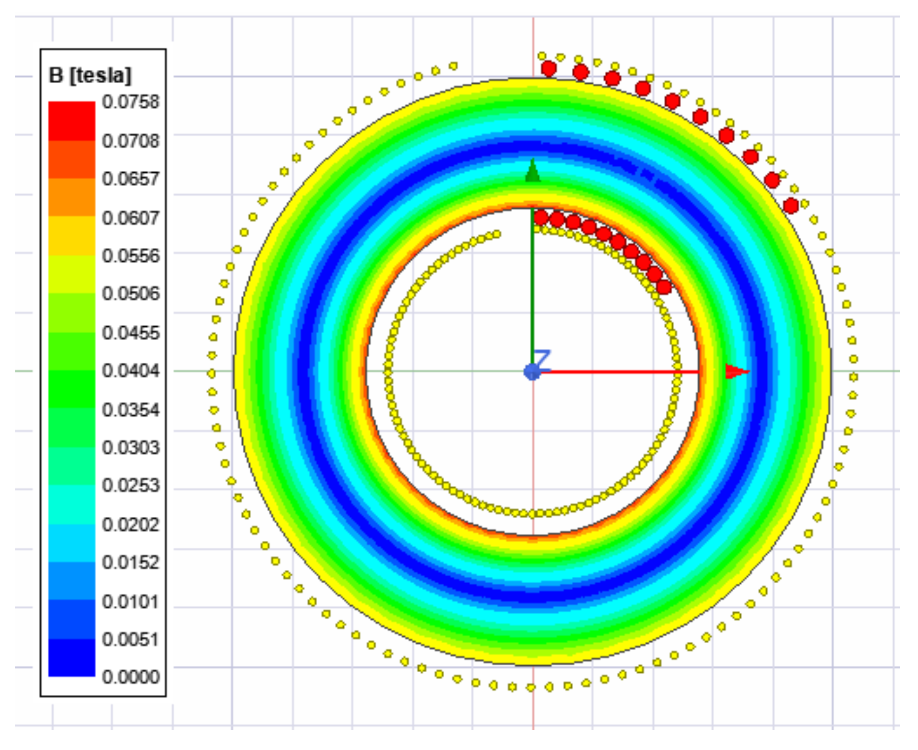
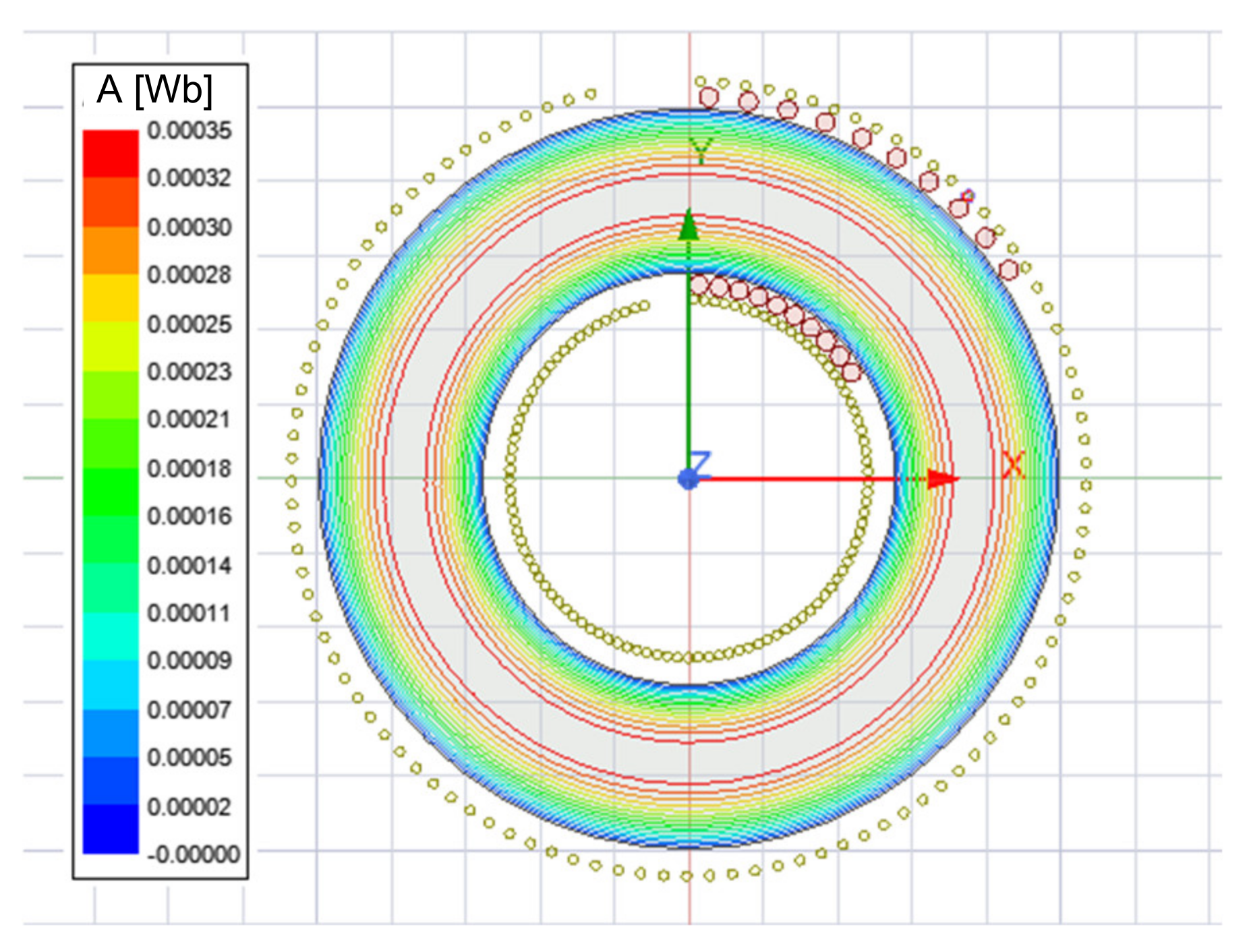
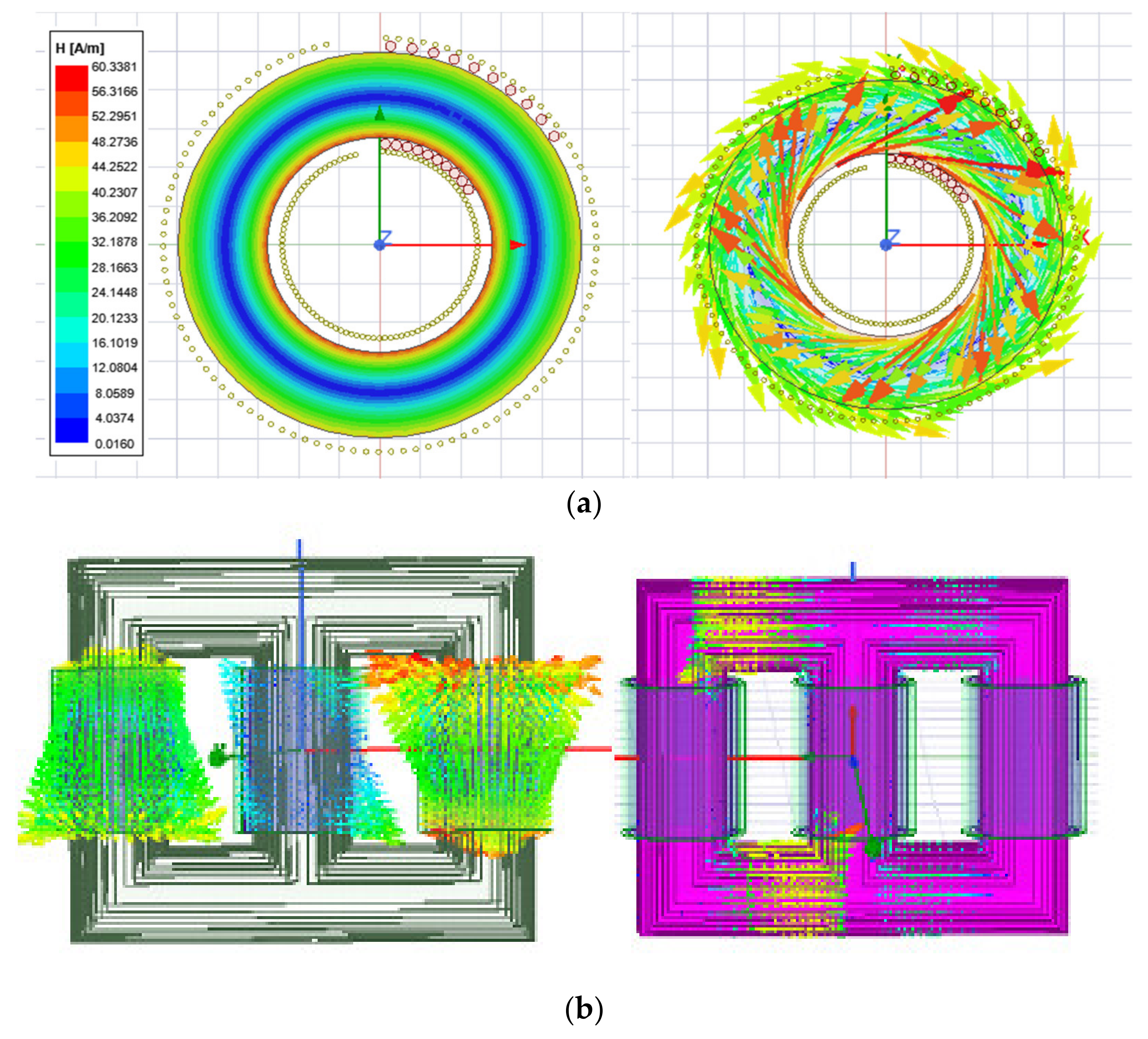
4. Transformer’s Magnetic Flux Density, Intensity and Flux Lines
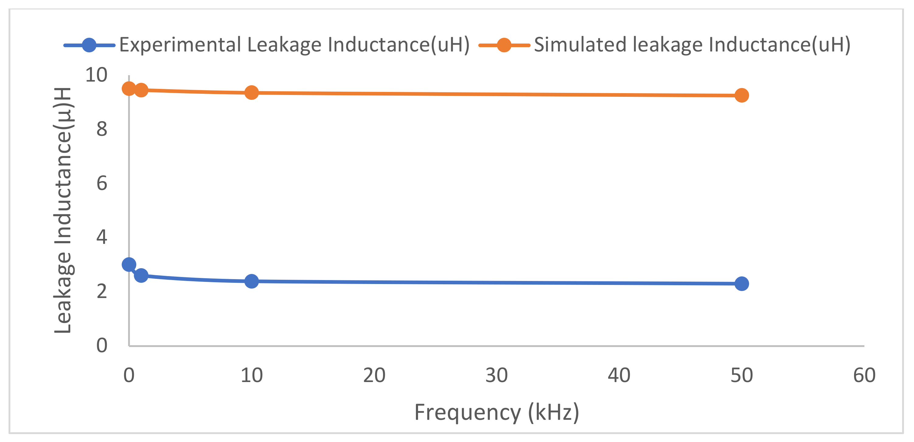
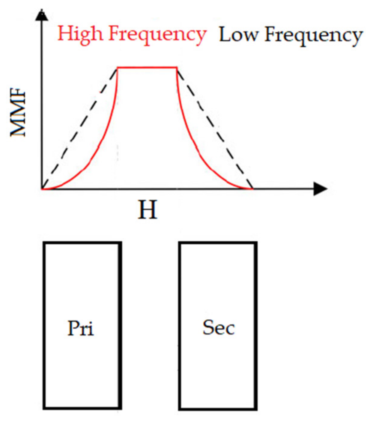
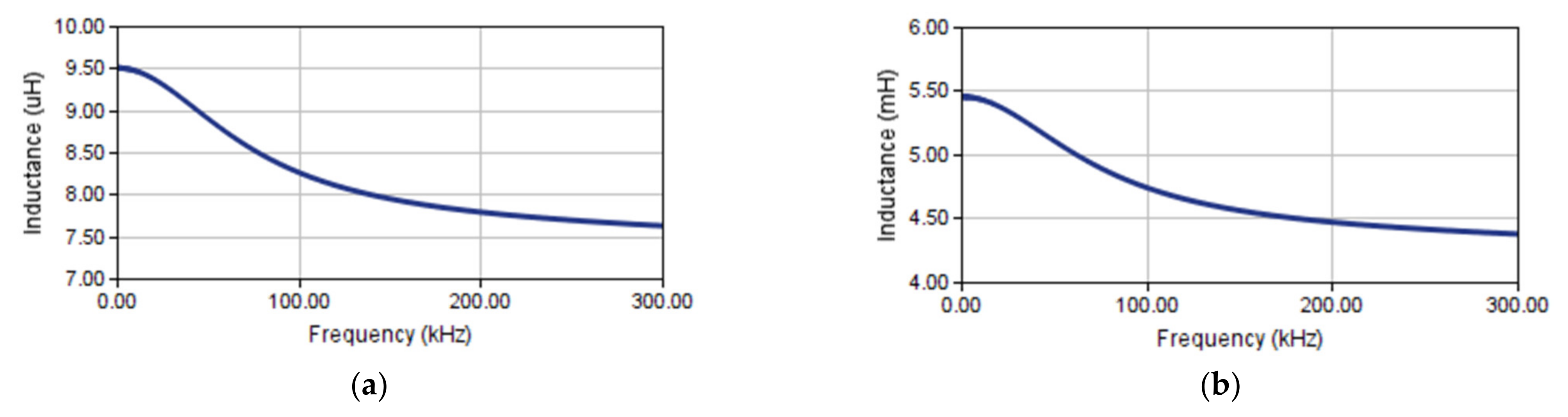
5. Leakage Inductance of a Toroidal Transformer
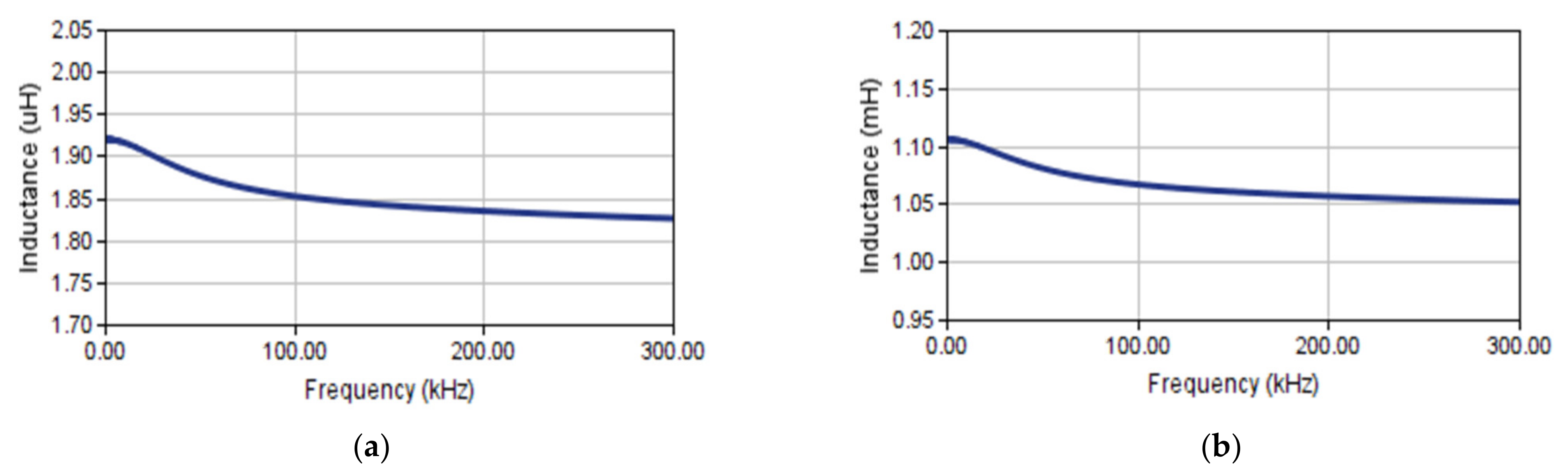
5.1. Case: 1
5.2. Case: 2
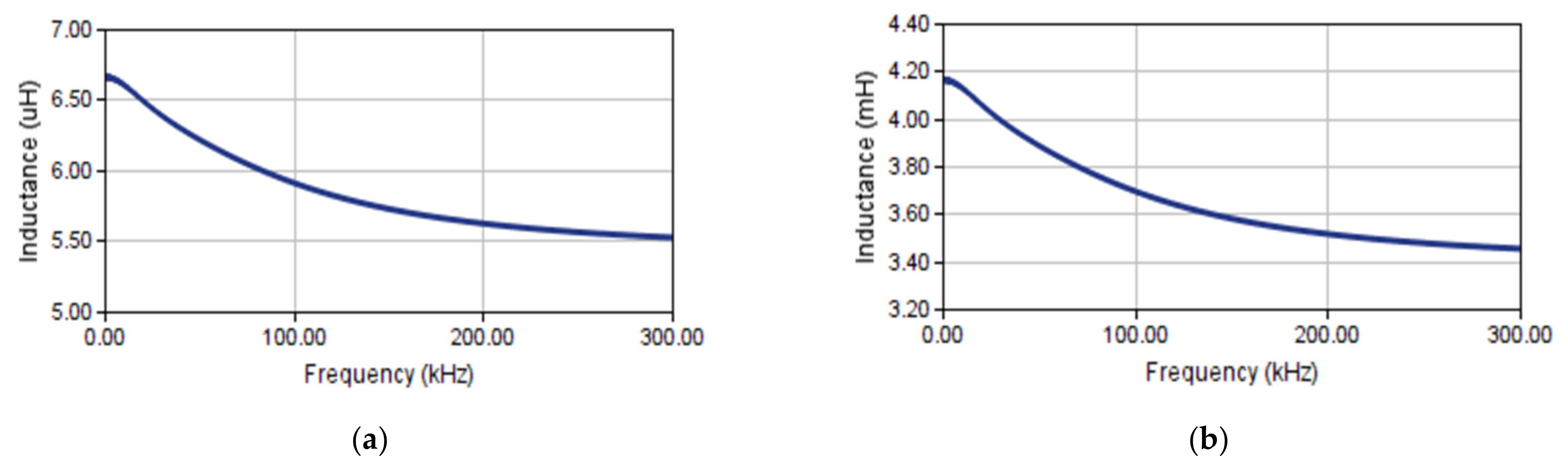
5.3. Case: 3
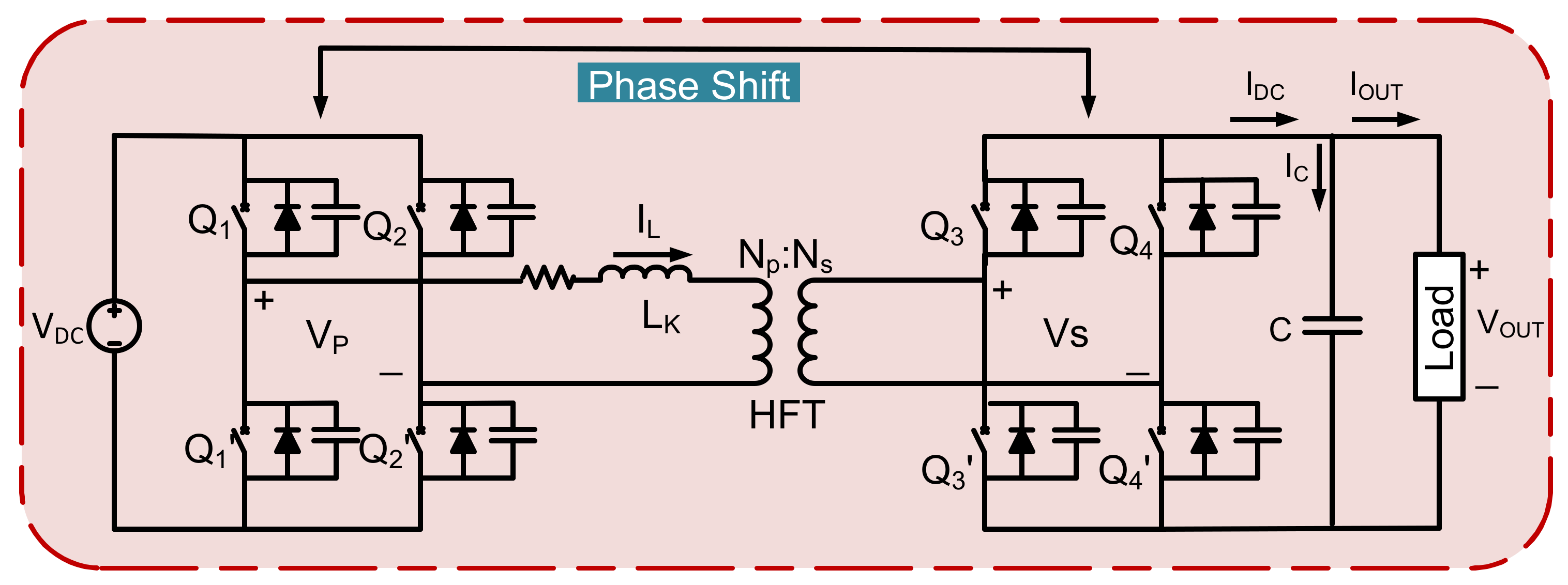
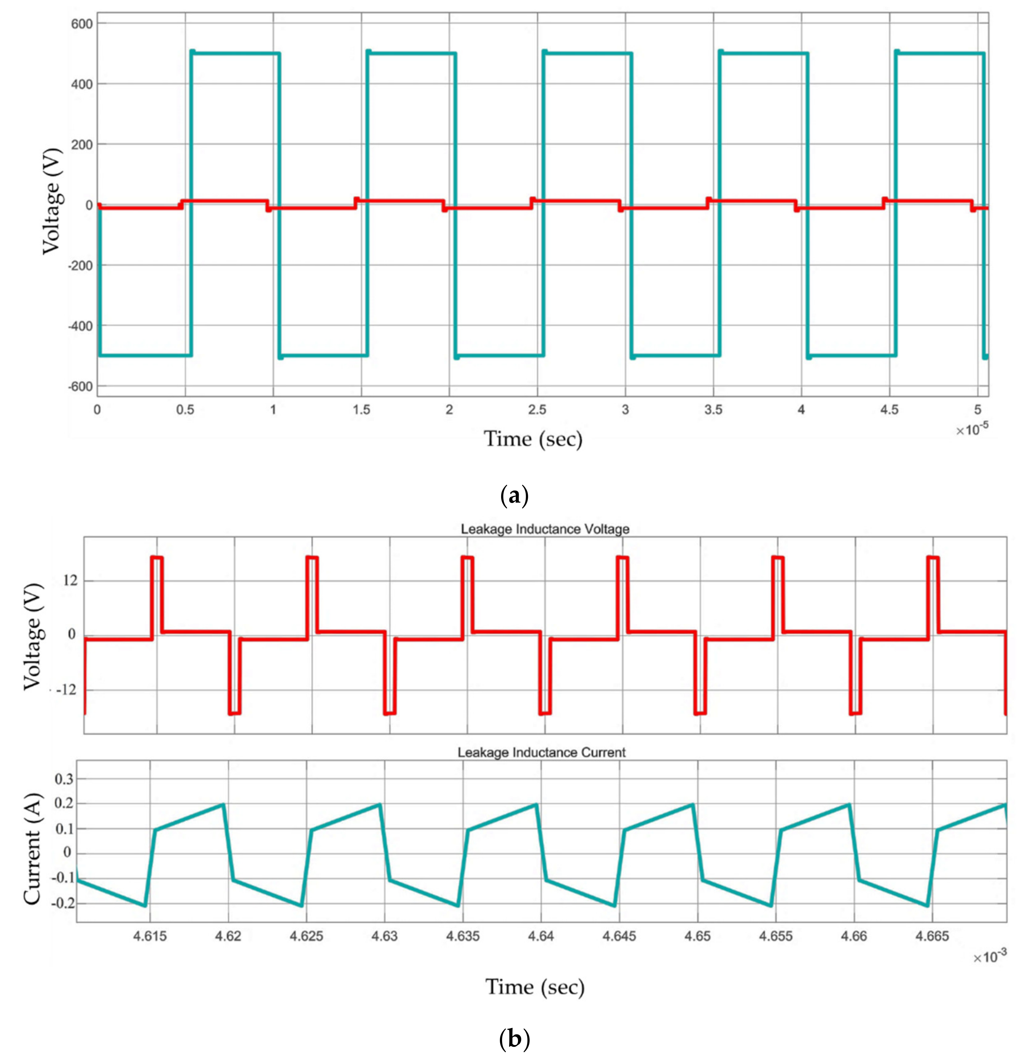
6. Simulation Results of DAB Converter
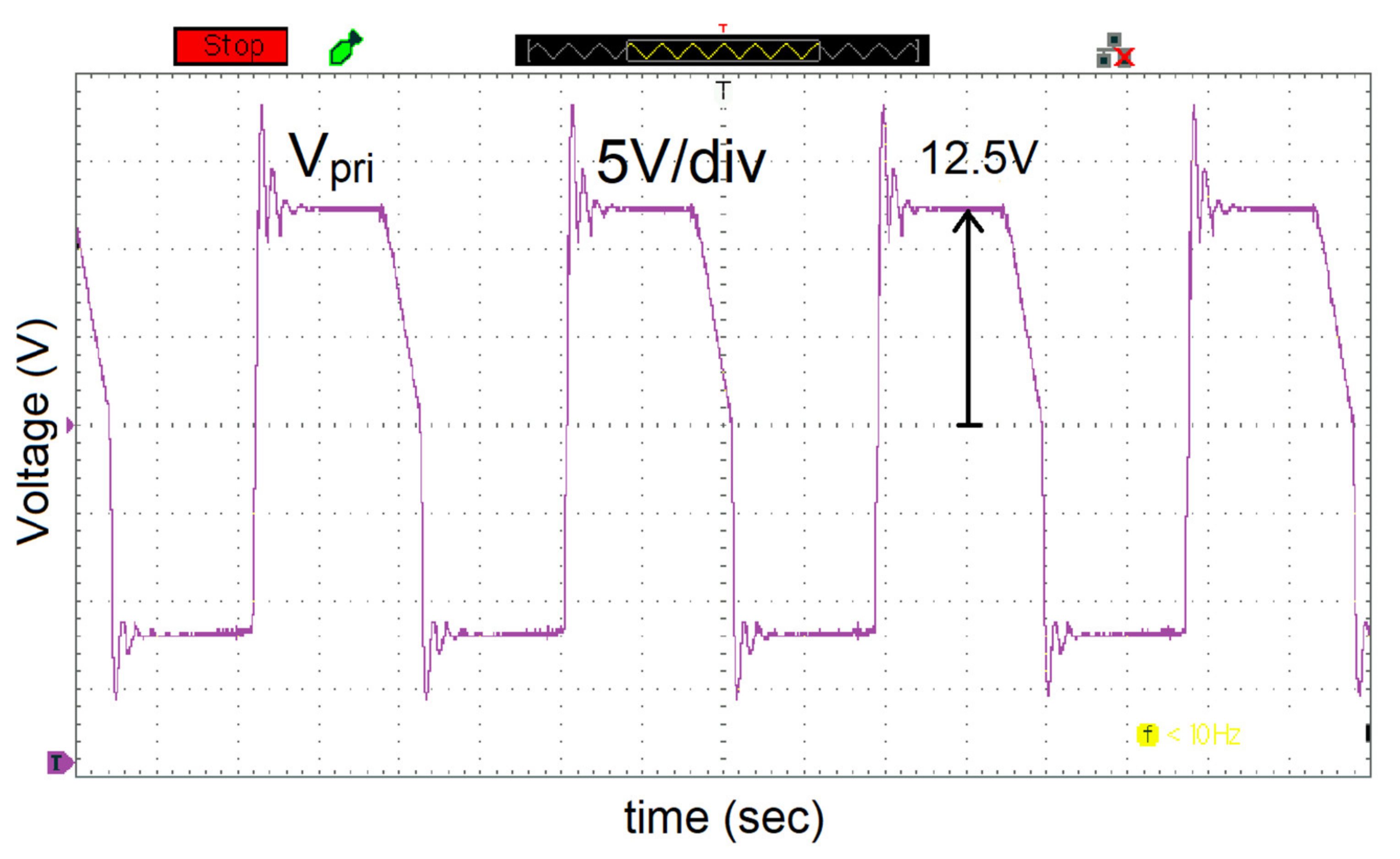
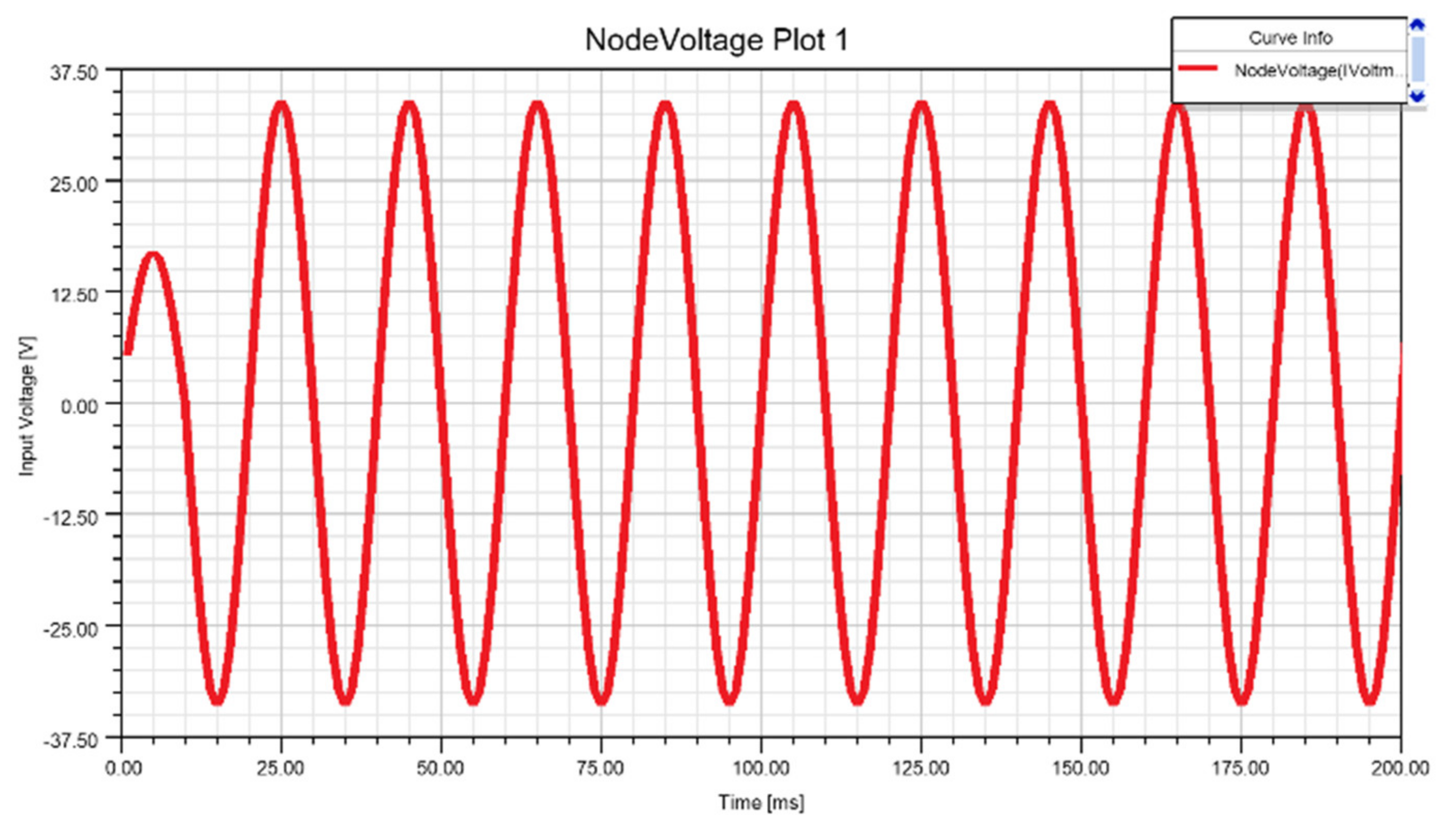
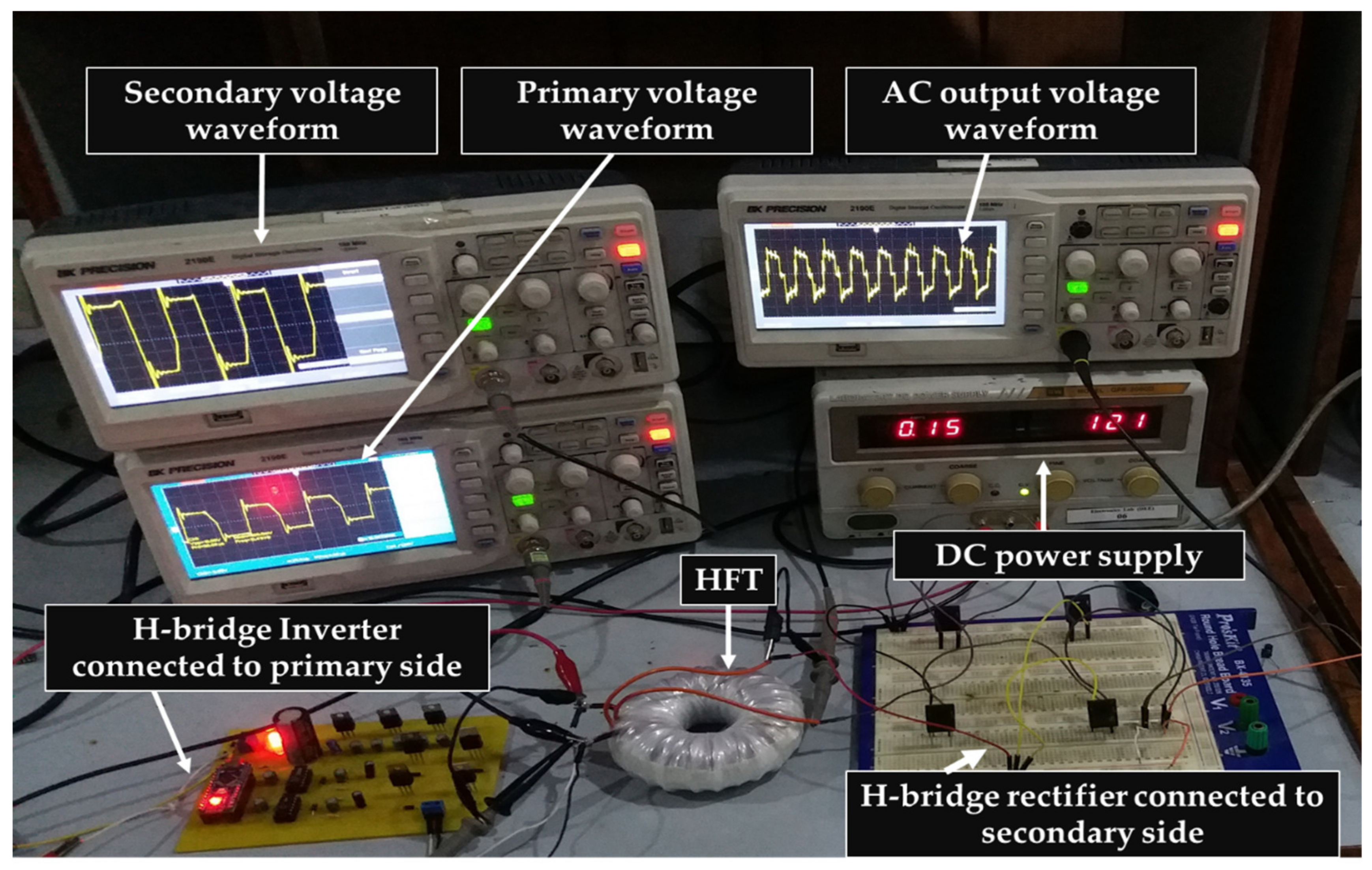
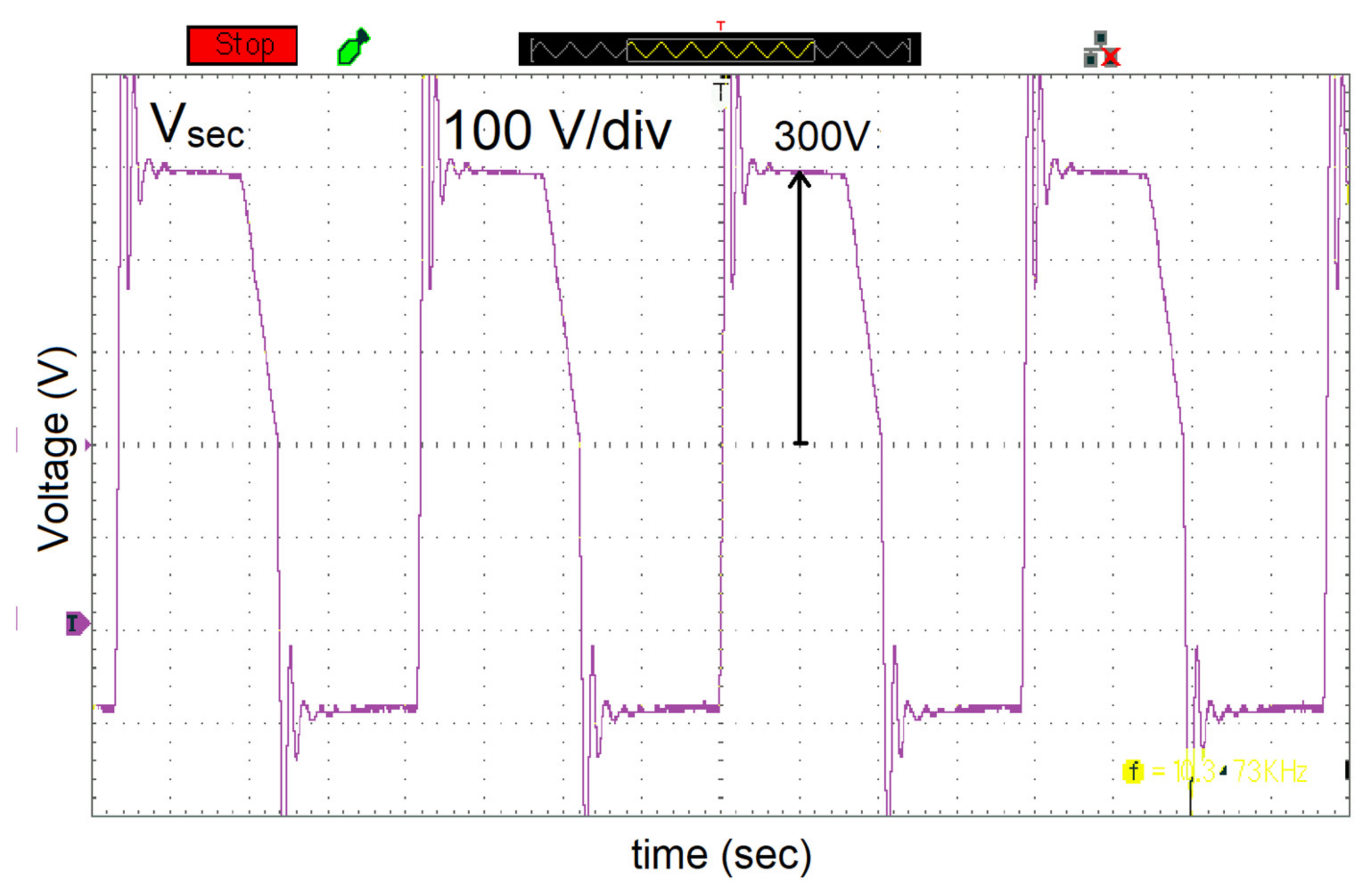
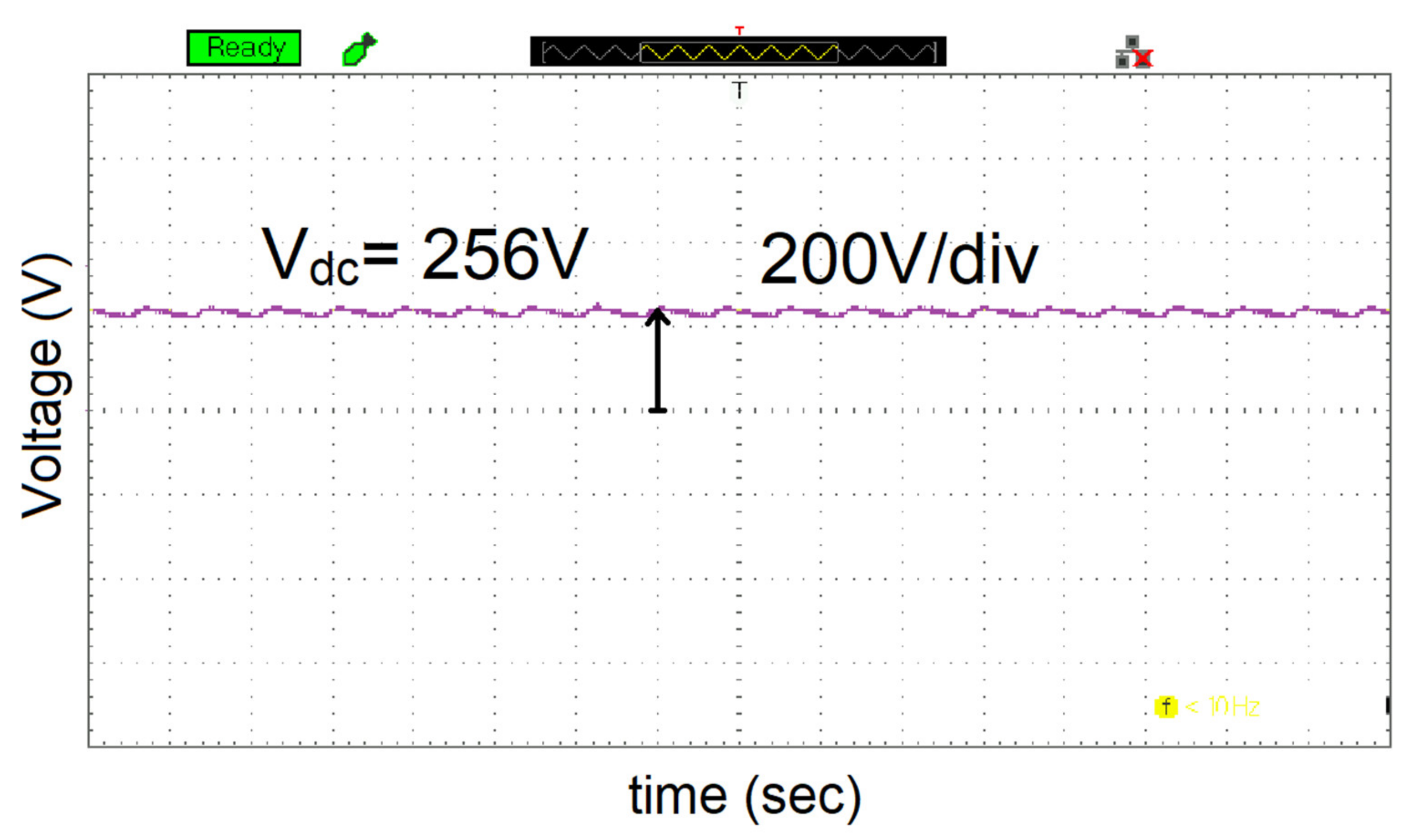
7. Experimental Validation
8. Discussion
- Instead of employing a conventional shell-type or core-type transformer, a high-frequency toroidal transformer was designed using FEM.
- Since leakage inductance is a crucial component in limiting power transfer in DAB converters, it was analyzed as a function of frequency under various circumstances and minimal leakage inductance was attained.
- A toroidal transformer with low leakage inductance was employed in the DAB converter and the simulated findings were confirmed using an experimental prototype.
- Besides leakage inductance, parasitic capacitance could also be obtained using FEM and the behavior of the DAB converter could be studied.
9. Conclusions
Author Contributions
Funding
Institutional Review Board Statement
Informed Consent Statement
Data Availability Statement
Conflicts of Interest
References
- Fouineau, A.; Raulet, M.A.; Lefebvre, B.; Burais, N.; Sixdenier, F. Semi-analytical methods for calculation of leakage inductance and frequency-dependent resistance of windings in transformers. IEEE Trans. Magn. 2018, 54, 1–10. [Google Scholar] [CrossRef]
- Zhao, X.; Liu, X.; Zhao, H.; Li, Y.; Liu, Y.; Yuan, D. Two-dimensional vector hysteresis modeling for soft magnetic composite materials considering anisotropic property. In Proceedings of the 2020 IEEE Industry Applications Society Annual Meeting, Detroit, MI, USA, 10–16 October 2020; pp. 1–6. [Google Scholar]
- Bahmani, M.A.; Thiringer, T.; Ortega, H. An accurate pseudo empirical model of winding loss calculation in HF foil and round conductors in switchmode magnetics. IEEE Trans. Power Electron. 2014, 29, 4231–4246. [Google Scholar] [CrossRef]
- De Leon, F.; Purushothaman, S.; Qaseer, L. Leakage inductance design of toroidal transformers by sector winding. IEEE Trans. Power Electron. 2014, 29, 473–480. [Google Scholar] [CrossRef]
- Naayagi, R.T.; Forsyth, A.; Shuttleworth, R. High-power bidirectional dc-dc converter for aerospace applications. IEEE Trans. Power Electron. 2012, 27, 4366–4379. [Google Scholar] [CrossRef]
- Alonso, A.; Sebastian, J.; Lamar, D.; Hernando, M.; Vazquez, A. An overall study of a dual active bridge for bidirectional dc/dc conversion. In Proceedings of the 2010 IEEE Energy Conversion Congress and Exposition, Atlanta, GA, USA, 12–16 September 2010; pp. 1129–1135. [Google Scholar]
- De Doncker, R.; Divan, D.; Kheraluwala, M. A three-phase soft switched high-power-density dc/dc converter for high-power applications. IEEE Trans. Ind. Appl. 1991, 27, 63–73. [Google Scholar] [CrossRef]
- Bahmani, M.A. Accurate Evaluation of Leakage Inductance in High-Frequency Transformers Using an Improved Frequency-Dependent Expression. IEEE Trans. Power Electron. 2015, 30, 5738–5746. [Google Scholar] [CrossRef]
- Bahmani, M.A. Design and Optimization of HF Transformers for High Power dc-dc Applications. Licentiate Thesis, Chalmers University of Technology, Gothenburg, Sweden, April 2014. [Google Scholar]
- Choi, J.-M.; Byen, B.-J.; Lee, Y.-J.; Han, D.-H.; Kho, H.-S.; Choe, G.-H. Design of leakage inductance in resonant DC-DC converter for electric vehicle charger. IEEE Trans. Magn. 2012, 48, 4417–4420. [Google Scholar] [CrossRef]
- Chen, K.; Kumar, N. Influence of isolation transformer leakage inductance on constant current output of class D series-parallel LCC-type resonant converter for light-emitting diode lighting application. IET Power Electron. 2014, 7, 1362–1373. [Google Scholar] [CrossRef]
- Muhammad, K.S.; Lu, D.-C. Magnetically isolated gate driver with leakage inductance immunity. IEEE Trans. Power Electron. 2014, 29, 1567–1572. [Google Scholar] [CrossRef]
- Stadler, A.; Albach, M. The influence of the winding layout on the core losses and the leakage inductance in high frequency transformers. IEEE Trans. Magn. 2006, 42, 735–738. [Google Scholar] [CrossRef]
- Zhang, K.; Chen, W.; Cao, X.; Pan, P.; Azeem, S.W.; Qiao, G.; Deng, F. Accurate calculation and sensitivity analysis of leakage inductance of high-frequency transformer with Litz wire winding. IEEE Trans. Power Electron. 2019, 35, 3951–3962. [Google Scholar] [CrossRef]
- Zheng, T.; Zhao, Y.J.; Ying, J.; Chen, P.L.; Zhang, F.F. Design and analysis on the turn-to-turn fault protection scheme for the control winding of a magnetically controlled shunt reactor. IEEE Trans. 2015, 30, 967–975. [Google Scholar] [CrossRef]
- Dowell, P.L. Effects of eddy currents in transformer windings. Proc. IEEE 1966, 113, 1387–1394. [Google Scholar] [CrossRef]
- Snelling, E.C. Soft Ferrites—Properties and Applications, 2nd ed.; Butterworth: London, UK, 1988. [Google Scholar]
- Kazimierczuk, M.K. High-Frequency Magnetic Components, 2nd ed.; Wiley: Chichester, UK, 2009. [Google Scholar]
- D’Antonio, M.; Chakraborty, S.; Khaligh, A. Planar transformer with asymmetric integrated leakage inductance using horizontal air gap. IEEE Trans. Power Electron. 2021, 36, 14014–14028. [Google Scholar] [CrossRef]
- Schlesinger, R.; Biela, J. Comparison of analytical models of transformer leakage inductance: Accuracy versus computational effort. IEEE Trans. Power Electron. 2020, 36, 146–156. [Google Scholar] [CrossRef]
- Ouyang, Z.; Thomsen, O.C.; Andersen, M.A.E. Optimal design and tradeoff analysis of planar transformer in high-power dc–dc converters. IEEE Trans. Ind. Electron. 2012, 59, 2800–2810. [Google Scholar] [CrossRef]
- Zhang, J.; Ouyang, Z.; Duffy, M.C.; Andersen, M.A.E.; Hurley, W.G. Leakage inductance calculation for planar transformers with a magnetic shunt. IEEE Tran. Ind. Appl. 2014, 50, 4107–4112. [Google Scholar] [CrossRef]
- Ostrenko, M.; Andriienko, B. Transformer impulse surges calculation by FEM coupled to the circuit. IEEE Trans. Magn. 2017, 53, 1–4. [Google Scholar] [CrossRef]
- Ouyang, Z. Calculation of leakage inductance for high frequency transformer. IEEE Trans. Power Electron. 2015, 30, 5769–5776. [Google Scholar] [CrossRef]
- Rothmund, D.; Guillod, T.; Bortis, D.; Kolar, J.W. 99.1% efficient 10 kV SiC-based medium-voltage ZVS bidirectional single-phase PFC AC/DC stage. IEEE J. Emerg. Sel. Top. Power Electron. 2018, 7, 779–797. [Google Scholar] [CrossRef]
- Bird, L.; Milligan, M.; Lew, D. Integrating Variable Renewable Energy: Challenges and Solutions; National Renewable Energy Laboratory: Golden, CO, USA, 2013. [Google Scholar]
- Michaud, A. Electr omagnetism According to Maxwell’s Initial Interpretation. J. Mod. Phys. 2019, 11, 16–80. [Google Scholar] [CrossRef]
- Ariani, H.A.; Iskender, I.; Karakaya, M. Performance analysis of a distribution transformer using ansys maxwell. Int. J. Tech. Phys. Probl. Eng. 2020, 12, 57–62. [Google Scholar]
- Del Vecchio, R.M.; Poulin, B.; Feghali, P.; Shah, D.; Ahuja, R. Transformer Design Principles: With Applications to Core-Form Power Transformers; CRC Press: Boca Raton, FL, USA, 2010. [Google Scholar]
- SimScale.com. What Is FEA|Finite Element Analysis. Available online: https://www.simscale.com/docs/content/simwiki/fea/whatisfea.html?utm_source=Blog&utm_medium=SimWiki%20Button&utm_campaign=SimWiki (accessed on 1 November 2018).
- Hamed, A.; Alyousef, A. Electrical Power Transformer; Blekinge Institute of Technology (BTH): Karlskrona, Sweden, 2016. [Google Scholar]
- Özüpak, Y. Performing structural design and modelling of transformer using ansys Maxwel. J. Brill. Eng. 2021, 2, 38–42. [Google Scholar] [CrossRef]
- Amirbande, M.; Vahedi, A. Calculation of leakage inductance in toroidal core transformer with non-interleaved windings. IEEE Trans. Ind. Electron. 2020, 48, 4215–4220. [Google Scholar] [CrossRef]
- Krismer, F.; Kolar, J.W. Efficiency-optimized high-current dual active bridge converter for automotive applications. IEEE Trans. Ind. Electron. 2012, 59, 2745–2760. [Google Scholar] [CrossRef]
- Karim, S.; Pamela, M. AESO Transformer Modelling Guide (PDF). Calgary: AESO—Alberta Electric System Operator (Prepared by Teshmont Consultants LP). 2018; p. 304. Available online: https://www.aeso.ca/assets/linkfiles/4040.002-Rev02-Transformer-Modelling-Guide.pdf (accessed on 2 August 2022).


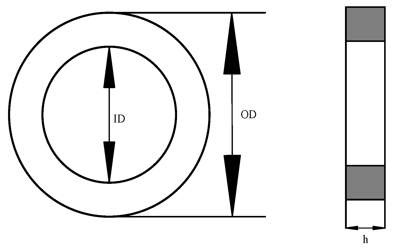
| Dimensions and Characteristics | Values | |
|---|---|---|
| Outer diameter | OD | 80 mm |
| Inner diameter | ID | 50 mm |
| Core height | h | 20 mm |
| Effective length | le | 197 mm |
| Effective cross-section area | Ae | 295 mm2 |
| Parameter | Formula | Value | |
|---|---|---|---|
| Primary Side | Power rating (VA) | (Known) | 1 KVA |
| Primary voltage (VP) | (Known) | 24 V | |
| Current (IP) | (8) | 41.66 A | |
| Wire Gauge | (standard table) | 10 SWG | |
| Secondary Side | Secondary Voltage (VS) | (Known) | 600 V |
| Current (IS) | (8) | 1.66 A | |
| Wire Gauge | (standard table) | 18 SWG |
| Design Parameter | Values |
|---|---|
| Rating power | 1 kVA |
| High voltage (Secondary Side) | 600 V |
| Low voltage (Primary Side) | 24 V |
| Frequency | 10 kHz |
| Core material | Ferrite N41 |
| Case: 1 | Case: 2 | Case: 3 | |
|---|---|---|---|
| Frequency | 50 k | 20 k | 10 k |
| BMAX | 0.1 Tesla | 0.1 Tesla | 0.1 Tesla |
| Primary Turns | 5 | 15 | 24 |
| Secondary Turns | 120 | 375 | 600 |
| Area | 295 mm2 | 295 mm2 | 295 mm2 |
| LK (Analytical) | 3 µH | 9 µH | 9.65 µH |
| LK (Simulated) | 1.88 µH | 8.5 µH | 9.5 µH |
| Circuit Parameters | Values | |
|---|---|---|
| Input Voltage | Vin | 12 V (DC) |
| Output Voltage (DAB) | Vout | 294 V (DC) |
| Turns Ratio | NP:NS | 1:25 |
| Switching frequency | fS(VSI) | 10 kHz |
| Switching frequency | fS(DAB) | 10 KHz |
| DC capacitance | C | 10 mF |
| Nominal Output Power | PO | 1 KW |
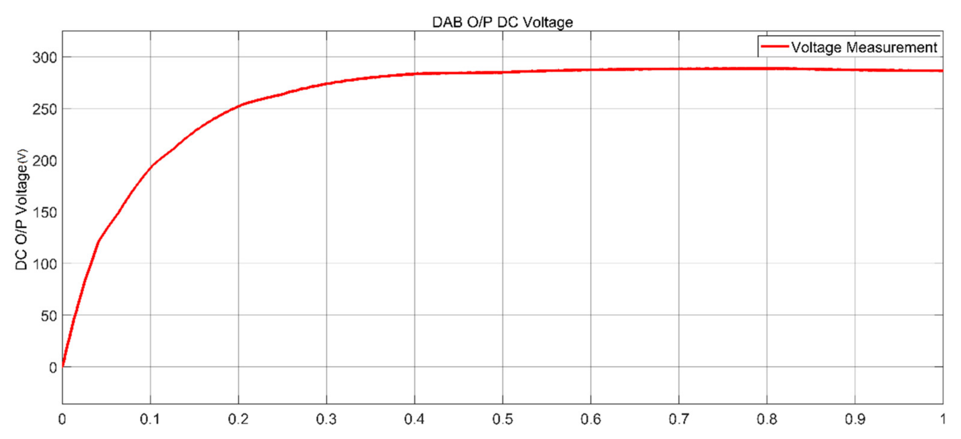
| Parameters | Simulated Values | Experimental Values |
|---|---|---|
| Primary Voltage | 12 V | 12 V |
| Secondary Voltage | 270 V | 275 V |
| DAB output Voltage | 286.5 V | 256 V |
Publisher’s Note: MDPI stays neutral with regard to jurisdictional claims in published maps and institutional affiliations. |
© 2022 by the authors. Licensee MDPI, Basel, Switzerland. This article is an open access article distributed under the terms and conditions of the Creative Commons Attribution (CC BY) license (https://creativecommons.org/licenses/by/4.0/).
Share and Cite
Ataullah, H.; Iqbal, T.; Khalil, I.U.; Mohammad, A.-S.; Ullah, N.; Emad Farrag, M. Analysis and Verification of Leakage Inductance Calculation in DAB Converters Based on High-Frequency Toroidal Transformers under Different Design Scenarios. Energies 2022, 15, 6176. https://doi.org/10.3390/en15176176
Ataullah H, Iqbal T, Khalil IU, Mohammad A-S, Ullah N, Emad Farrag M. Analysis and Verification of Leakage Inductance Calculation in DAB Converters Based on High-Frequency Toroidal Transformers under Different Design Scenarios. Energies. 2022; 15(17):6176. https://doi.org/10.3390/en15176176
Chicago/Turabian StyleAtaullah, Haris, Taosif Iqbal, Ihsan Ullah Khalil, Al-Sharef Mohammad, Nasim Ullah, and Mohamed Emad Farrag. 2022. "Analysis and Verification of Leakage Inductance Calculation in DAB Converters Based on High-Frequency Toroidal Transformers under Different Design Scenarios" Energies 15, no. 17: 6176. https://doi.org/10.3390/en15176176
APA StyleAtaullah, H., Iqbal, T., Khalil, I. U., Mohammad, A.-S., Ullah, N., & Emad Farrag, M. (2022). Analysis and Verification of Leakage Inductance Calculation in DAB Converters Based on High-Frequency Toroidal Transformers under Different Design Scenarios. Energies, 15(17), 6176. https://doi.org/10.3390/en15176176