Article

Research on Autonomous Cutting Method of Cantilever Roadheader

School of Mines, China University of Mining and Technology, Xuzhou 221116, China
*
Author to whom correspondence should be addressed.
Energies 2022, 15(17), 6190; https://doi.org/10.3390/en15176190
Submission received: 5 August 2022 / Revised: 22 August 2022 / Accepted: 24 August 2022 / Published: 25 August 2022
(This article belongs to the Special Issue Intelligent Coal Mining Technology)

Abstract

:
Roadway excavation is the leading project in coal mining, and the cantilever roadheader is the main equipment in roadway excavation. Autonomous cutting by cantilever roadheaders is the key to realize safe, efficient and intelligent tunneling for underground roadways. In this paper, the working device of a cantilever roadheader was simplified into a series of translation or rotation joints, and the spatial pose model and spatial pose coordinate system of the roadheader were established. Using the homogeneous transformation matrix and the robot-related theory, the space pose transformation matrix of the roadheader and the space pose equation of the cutting head of the roadheader were derived. The forward kinematics and inverse kinematics of the cutting head were solved by using the D-H parameter method and an inverse transformation method. The location coordinates of the inflection point of the cutting process path for a rectangular roadway were determined, and cutting path planning and control were carried out based on the inflection point coordinates. Finally, MATLAB software was used to simulate the limit cutting area of the cutting head and the cutting process path. The simulation results showed that the limit cutting section had a bulging waist shape, the boundary around the roadway was flat, and the roadway cutting error was controlled within 1mm, which verified the reliability and effectiveness of the autonomous cutting theory of the roadheader. It lays a mathematical model and theoretical foundation for the realization of “autonomous operation of unmanned tunneling equipment”.

1. Introduction

Coal is an indispensable energy source for global development. Its consumption accounts for about 30% of the world’s total energy consumption and 70% of China’s total primary energy consumption [1]. Coal mining cannot be separated from roadway excavation, which can be said to be the leading project in coal production [2,3]. The cantilever roadheader is the main equipment for roadway excavation; it is used to excavate roadways and prepare for the layout of the coal mining face. With the increase in mining depth, the underground geological conditions and working environment gradually become more complex and dangerous. In order to ensure the safety of underground operations, coal mining equipment is gradually developing towards automation, intelligent and unmanned. On the premise of selecting a cantilever-type roadheader suitable for the underground geology and working environment, making the cantilever-type roadheader perform independent cutting according to the planned trajectory is the key to realize safe, efficient and intelligent tunneling of underground roadways.
Therefore, many scholars at home and abroad have done a great deal of research on the kinematics, dynamics, and control of roadway formation in the cutting process of roadheaders and the selection of roadheader equipment. Ning et al. established a cutting model with a trapezoidal roadway interface, used the approximate iterative method to determine the inflection point for the position of cutting, and simulated it through MATLAB software, which greatly improved the cutting and formation of roadways [4]. Fan et al. established a structural ring compensation model for spatial attitude deviation based on the structural analysis of a cantilever roadheader and proposed an intelligent optimization and combination compensation strategy to adjust the real-time attitude of the roadheader and improve the roadway cutting accuracy [5]. Liu et al. analyzed the outer contour of roadway formation by the cantilever roadheader’s cutting head under the influence of vibration, which provided a basis for optimizing the cutting parameters and high-precision formation control of the roadheader [6]. Tian et al. analyzed the compression breaking force of the cutting head in the tunneling process, described the cutting trajectory planning method of any section, and simulated the limit cutting area. Finally, combined with a field test, the effectiveness of the cutting trajectory planning method was verified [7]. Dolipski et al. studied the relationship between the speed of the roadheader’s cutting head and the energy consumption of cutting [8]. Wang et al. proposed an automatic cutting and formation control system for an arbitrary roadway section [9]. Zhao et al. regarded the path-planning problem of roadheaders in an unstructured environment as a general network problem; they put forward a minimum-cost modeling method and optimized the path by using a genetic particle swarm optimization algorithm, which provides a basis for the study of attitude correction of roadheaders [10]. Liu et al. optimized the cutting head parameters according to the strength of relevant rocks and obtained accurate roadway cutting sections [11]. Zhao established a trajectory correction model for the robot system and proposed a controller to compensate the spatial pose of the robot [12]. Zhang et al. divided the roadway environment into regional grids, established the TBM model in these grids, and combined PID and neural network algorithms to realize the automatic deviation correction of the TBM [13]. Zhang et al. used a particle swarm optimization algorithm and PID to adjust the pitching angle of the roadheader [14]. Ding et al. established the space posture model of the cantilever roadheader, which provided the basis for dynamically adjusting the space posture of the roadheader [15]. Wang et al. proposed a control method for automatic section cutting and formation based on the combination of an oil cylinder stroke sensor and an FCC electrical control system, which realized the automatic cutting of an underground coal roadway [16]. Tuncer et al. proposed a dynamic path-planning method for mobile robots based on an improved genetic algorithm [17]. Li et al., according to the principle of equipment-matching selection, proposed a method of equipment-matching selection for roadheaders [18]. Li et al. developed an on-line selection system for roadheaders based on LAN, which makes the selection of roadheader equipment more accurate, convenient and efficient [19].
Based on the existing technology and theoretical research at home and abroad, according to the composition of each working device of the roadheader, the author used the improved D-H parameter method to establish a spatial pose model of the cantilever roadheader and deduced a spatial pose transformation matrix of the cutting head relative to each mechanism of the roadheader. In addition, based on the cutting process path for a rectangular section, a method to determine the coordinates of the inflection point of the path was proposed to form the planning and control of the cutting process path. Finally, taking an EBZ-200 roadheader as an example, a simulation of the cutting head’s limit cutting area and cutting process path was carried out by substituting the relevant parameters of the EBZ-200 roadheader into MATLAB software, which verified the reliability and effectiveness of the theory. It lays a mathematical model and theoretical foundation for the realization of “autonomous operation of unmanned tunneling equipment”.

2. Modeling and Analysis of Space Pose of Cantilever Roadheader

2.1. Modeling Method of Space Pose of Roadheader

The working device of a cantilever roadheader is connected by a series of translation or rotation joints [20]. A degree of freedom is formed between each pair of joints and the connecting rod. In order to describe the translation and rotation relationship between adjacent connecting rods, Denavt and Hartenberg proposed to establish a connecting rod coordinate system at each joint and used a 4-dimensional homogeneous transformation matrix ( T n n 1 ) to express the position transformation relationship between a connecting rod coordinate system and its previous connecting rod coordinate system, that is, the D-H parameter method.
The D-H parameter method is divided into the standard D-H parameter method and the modified D-H parameter method. The differences between the standard D-H parameter method and the modified D-H parameter method are shown in Table 1, in which: θ is the angle of rotation around the Z axis, D represents the distance of translation along the Z axis, α represents the angle of rotation around the X axis and the distance of translation along the X axis.
A large number of studies have shown that the standard D-H parameter method is only applicable to robots with an open-chain structure, while the modified D-H parameter method is applicable to robots with an open-chain structure, tree structure or closed-chain structure and has the advantage of wide applicability. Therefore, this paper used the modified D-H parameter method to analyze the spatial pose modeling of a cantilever roadheader.

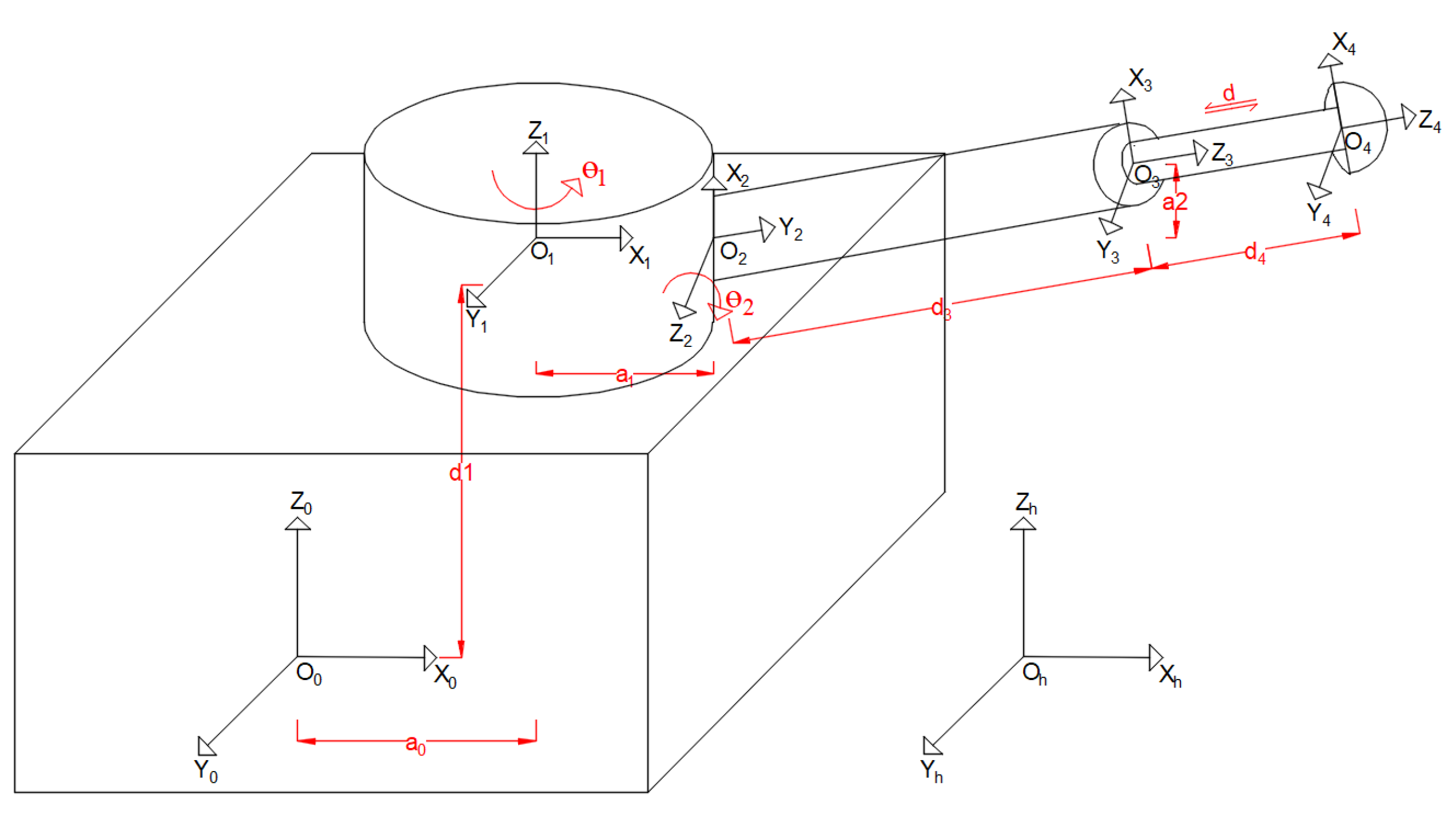
2.2. Establishment of Space Position and Orientation Coordinate System of Roadheader

The robotized roadheader model and the connecting rod parameters of its working device are shown in Figure 1.
In the figure, Oh-XhYhZh is the roadway coordinate system, which is the basis of the entire roadway operation process.
O0-X0Y0Z0 is the coordinate system of the center of gravity of the roadheader body, which is convenient to establish the coordinate system of the relationship between the cutting head and the roadheader body.
Oi-XiYiZi (i = 1, 2, 3, 4) is the coordinate system of the working device of the roadheader, which is established at the geometric center of gravity of the roadheader and the joints of each connecting rod, so as to describe the relationship between the previous relative positions and transformations of each connecting rod of the roadheader. Among them, O1-X1Y1Z1 is the turret coordinate system, O2-X2Y2Z2 is the cantilever coordinate system, O3-X3Y3Z3 is the telescopic coordinate system, and O4-X4Y4Z4 is the cutting head coordinate system.
In addition, a0 is the translation distance along the O0X0 axis, a1 is the translation distance along the O1X1 axis, and a2 is the translation distance along the O2X2 axis. θ1 represents the rotation angle around the O1Z1 axis (the rotation angle of the rotary table), and θ2 represents the rotation angle around the O2Z2 axis (the rotation angle of the cantilever in the vertical plane). d1 is the translation distance along the O1Z1 axis, d3 is the translation distance along the O3Z3 axis (the length of the cantilever), d4 is the translation distance along O4Z4 (the elongation of the cutting part), and d is the telescopic stroke of the cutting head.

2.3. Derivation of Space Pose Matrix of Roadheader

2.3.1. Cutting Head to Fuselage Center of Gravity Pose Matrix

According to the principle of the D-H parameter method, the coordinates {xi, yi, zi} of any point in the coordinate system Oi-XiYiZi and the coordinates {xi−1, yi−1, zi−1} in the coordinate system Oi−1-Xi−1Yi−1Zi−1 satisfied the following equation:
{ x i 1 , y i 1 , z i 1 , 1 } T = T i i 1 { x i , y i , z i , 1 } T
Therefore, the coordinates of the point {x4, y4, z4} in the cutting head coordinate system in the heading machine center of gravity coordinate system were:
  { x 0 , y 0 , z 0 , 1 } T = T 1 0 · T 2 1 · T 3 2 · T 4 3 · { x 4 , y 4 , z 4 , 1 } T
That was:
{ x 0 , y 0 , z 0 , 1 } T = T 4 0 · { x 4 , y 4 , z 4 , 1 } T
The cutting head connecting rod parameters were established according to Figure 1, as shown in Table 2.
It was assumed that the center line of the roadheader body coincides with the designed center line of the roadway, and there was no pose deviation. According to the D-H parameter method and the cutting head connecting rod parameter table, the D-H transformation matrix between the coordinate systems of each working device of the roadheader was obtained as follows:
T 1 0 = [ cos θ 1 sin θ 1 0 a 0 sin θ 1 cos θ 1 0 0 0 0 1 d 1 0 0 0 1 ] ,   T 2 1 = [ cos θ 2 sin θ 2 0 a 1 0 0 1 0 sin θ 2 cos θ 2 0 0 0 0 0 1 ] T 3 2 = [ 1 0 0 a 2 0 0 1 ( d 3 + d ) 0 1 0 0 0 0 0 1 ] ,   T 4 3 = [ 1 0 0 0 0 1 0 0 0 0 1 d 4 0 0 0 1 ]
Therefore, the homogeneous transformation matrix( T 4 0 ) of the cutting head coordinate system O4-X4Y4Z4 relative to the heading machine body’s gravity center coordinate system O0-Z0Y0Z0 was:
T 4 0 = T 1 0 · T 2 1 · T 3 2 · T 4 3 = [ t 11 t 12 t 13 t 14 t 21 t 22 t 23 t 24 t 31 t 32 t 33 t 34 t 41 t 42 t 43 t 44 ]
Among:
t 11 = cos θ 1 cos θ 2 ,   t 12 = sin θ 1 ,   t 13 = cos θ 1 sin θ 2 , t 14 = a 0 + a 1 cos θ 1 + cos θ 1 sin θ 2 ( d + d 3 ) + a 2 cos θ 1 cos θ 2 + d 4 cos θ 1 sin θ 2 , t 21 = cos θ 2 sin θ 1 ,   t 22 = cos θ 1 ,   t 23 = sin θ 1 sin θ 2 , t 24 = a 1 sin θ 1 + ( d + d 3 ) sin θ 1 sin θ 2 + a 2 cos θ 2 sin θ 1 + d 4 sin θ 1 sin θ 2 , t 31 = sin θ 2 , t 32 = 0 ,   t 33 = cos θ 2 ,   t 34 = d 1 cos θ 2 ( d + d 3 ) d 4 cos θ 2 + a 2 sin θ 2 , t 41 = 0 ,   t 42 = 0 ,   t 43 = 0 ,   t 44 = 1

2.3.2. Heading Machine Body to Roadway Pose Matrix

When the roadheader is driving, it is inevitable that the body of the roadheader deviates from the center line of the roadway due to geological or manmade reasons. The correct expression of the heading machine body’s posture is the basis for realizing the accurate and directional cutting and posture correction of the heading machine. The “fuselage yaw angle α”, “fuselage pitch angle β”, “fuselage rolling angle γ” and “fuselage offset L” could be used to describe the posture of the cantilever roadheader [21,22], as shown in Figure 2 below. Among them, the OhXh axis coincides with the center line of the roadway design and points to the roadway section direction, the OhZh points to the roadway roof direction, and the OhXhYh plane represents the roadway floor.
According to the coordinate transformation theory, the coordinate system O0-X0Y0Z0 of the roadheader’s body’s gravity center was obtained from the roadway coordinate system Oh-ZhYhZh after four transformations: first rotating around the ohzh axis α angle, then rotating around the ohyh axis β angle, then rotating around the ohxh axis γ angle, and finally translating the vector L (Δx, Δy, Δz) along the oho0 axis. Therefore, the transformation matrix of the center of gravity coordinate system of the roadheader’s body relative to the roadway coordinate system was:
T 0 h = Rot ( Z h , α ) · Rot ( Y h , β ) · Rot ( X h , γ ) · Trans ( Δ X , Δ Y , Δ Z )
T 0 h = [ c α s α 0 0 s α c α 0 0 0 0 1 0 0 0 0 1 ] [ c β 0 s β 0 0 1 0 0 s β 0 c β 0 0 0 0 1 ] [ 1 0 0 0 0 c γ s γ 0 0 s γ c γ 0 0 0 0 1 ] [ 1 0 0 X 0 1 0 Y 0 0 1 Z 0 0 0 1 ] = [ c α c β s α c γ + c α s β s γ s α s γ + c α s β c γ c α c β X + ( c α s β s γ s α c γ ) Y + ( s α s γ + c α s β c γ ) Z s α c β c α c γ + s α s β s γ c α s γ + s α s β c γ s α c β X + ( c α c γ + s α s β s γ ) Y + ( s α s β c γ c α s γ ) Z s β c β s γ c β c γ s β X + c β s γ Y + c β c γ Z 0 0 0 1 ]
where c stands for cos, and s stands for sin.

2.4. Spatial Pose Analysis of Cutting Head of Roadheader

According to formula (2) and formula (4), the coordinates of the cutting head center O4 in the center of gravity coordinate system of the roadheader was:
x 0 = a 0 + a 1 cos θ 1 + cos θ 1 sin θ 2 ( d + d 3 ) + a 2 cos θ 1 cos θ 2 + d 4 cos θ 1 sin θ 2
y 0 = a 1 sin θ 1 + ( d + d 3 ) sin θ 1 sin θ 2 + a 2 cos θ 2 sin θ 1 + d 4 sin θ 1 sin θ 2
z 0 = d 1 cos θ 2 ( d + d 3 ) d 4 cos θ 2 + a 2 sin θ 2
The spatial pose matrix of the cutting head relative to the roadway coordinate system was:
T 4 h = T 0 h · T 4 0
Combining Equations (1), (4) and (7), it could be known that the points {x4, y4, z4} of the coordinates {xh, yh, zh} in the cutting head coordinate system in the roadway coordinate system met the following equation:
{ x h , y h , z h , 1 } T = T 0 h · T 4 0 { x 4 , y 4 , z 4 , 1 } T
Similarly, the coordinates of the cutting head center O4 in the roadway coordinate system could be obtained according to Equation (8).

3. Research on Trajectory Planning and Control of Cantilever Roadheader

The roadway section is formed by the movement of the cutting head traversing the section, and the shape of the section is related to the envelope of the cutting head’s movement. The trajectory line formed by connecting the coordinates of the position points of the cutting head traversing the cross-section, in turn, is the expected trajectory of the cutting head, which is also the cutting path of the cutting head. The rationality of cutting head trajectory planning and the accuracy of trajectory control determine the quality of roadway section formation. This section studied the trajectory planning and control of the cutting head of the roadheader.

3.1. Research on Cantilever Cutting Kinematics of Roadheader

According to the structure of the cantilever roadheader, it can be regarded as a roadheader robot for kinematic analysis. Kinematics problems can be divided into forward kinematics problems and inverse kinematics problems. The forward kinematics problem of the roadheader is that the geometric parameters and joint variables of the working rods of the roadheader are known, and the position and orientation of the cutting head of the roadheader can then be calculated relative to the given coordinate system. Generally, the D-H method is used to solve the forward kinematics problem, which can realize the accurate spatial position and attitude positioning of the cutting head. The inverse kinematics problem of roadheader is that the geometric parameters of each rod of the roadheader are known, and the joint variables of each rod when the position of the given cutting head can be solved relative to the overall coordinate system, which can realize the planning and precise control of the trajectory of the cutting head. The solution methods of inverse kinematics problems mainly include the analytical method, inverse transformation method, geometric method and inverse solution algorithm.
The forward kinematics of roadheader were solved by the D-H method in Section 2, and the inverse transformation method was then used to solve the inverse kinematics of roadheader.
The space pose matrix ( T 4 0 ) of the cutting head of the roadheader could also be expressed by the following formula:
T 4 0 = [ n x o x a x p x n y o y a y p y n z o z a z p z 0 0 0 1 ] = [ n o a p 0 0 0 1 ]
where n is the normal vector, o is the azimuth vector, a is the approach vector, and p is the position vector.
It can be known from Equation (9) that the variables of the cutting head space pose matrix in Equation (4) were equal to the corresponding elements of the matrix represented by joint variables in Equation (9). Thus, equations can be formed to solve the corresponding relationship between joint variables ( θ i and d i ) and n, o, a, p.
From the equality of the (1,2) and (2,2) elements of formula (4) and formula (9), we can obtain:
θ 1 = a r c t a n o x o y  
From the equality of the (3,1) and (3,3) elements of formula (4) and formula (9), we can obtain:
θ 2 = a r c t a n n z a z
From the corresponding equality of (1,4) of formula (4) and formula (9), we can obtain:
d = p x a 0 + ( a 1 + a 2 ) o y a 2 n x a x d 3 d 4  
Similarly, from the corresponding equality of the (2,4) and (3,4) elements of formula (4) and formula (9), we can obtain:
d = p y a 1 o x a 2 n y a y d 3 d 4  
d = a 2 n z + p z d 1 a z d 3 d 4  

3.2. Cutting Process Path Planning and Control

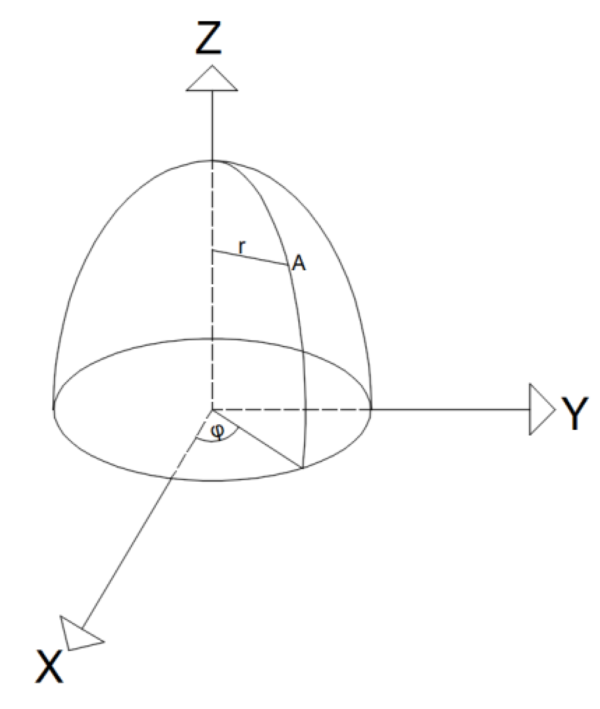
3.2.1. Determination of Pick Coordinate of Cutting Head

During the operation of the roadheader, the pick on the cutting head is used to cut the coal and rock surface. Therefore, after determining the roadway section form, the actual section boundary is formed when the curve of the pick is tangent to the section boundary. In order to simplify the calculation, the cutting head was regarded as the envelope surface of the rotating parabola generated by the parabola rotation, as shown in Figure 3. In the figure, A is any point on the paraboloid, and r is the distance from point a to the axis of rotation. If the equation of the parabola was Z = aX2 + c, then the equation of the rotating paraboloid formed by the rotation of the parabola around the Z axis was:
{ x = r c o s φ y = r s i n φ     z = a r 2 + c
If the coordinate vector of a pick i of the cutting head in the coordinate system O4-X4Y4Z4 was:
I 4 = { x i 4 , y i 4 , z i 4 , 1 }
then the coordinate of the pick i in the center of gravity coordinate system O0-X0 × 0Z0 of the machine body was:
{ x i 0 , y i 0 , z i 0 , 1 } = T 4 0 · I 4
Combining Equations (15)–(17), the coordinates of the pick i in the center of gravity coordinate system of the machine body were:
x i 0 = cos θ 1 cos θ 2 r i cos φ + sin θ 1 r i sin φ + cos θ 1 sin θ 2 ( ar i 2 + c + d 4 ) + a 0 + a 1 cos θ 1 + cos θ 1 cos θ 2 ( d + d 3 + a 2 )
y i 0 = cos θ 2 sin θ 1 r i cos φ cos θ 1 r i sin φ + sin θ 1 sin θ 2 ( ar i 2 + c ) + a 1 sin θ 1 + ( d + d 3 + d 4 ) sin θ 1 sin θ 2 + a 2 cos θ 2 sin θ 1
z i 0 = sin θ 2 r i cos φ cos θ 2 ( ar i 2 + c ) + d 1 cos θ 2 ( d + d 3 ) d 4 cos θ 2 + a 2 sin θ 2

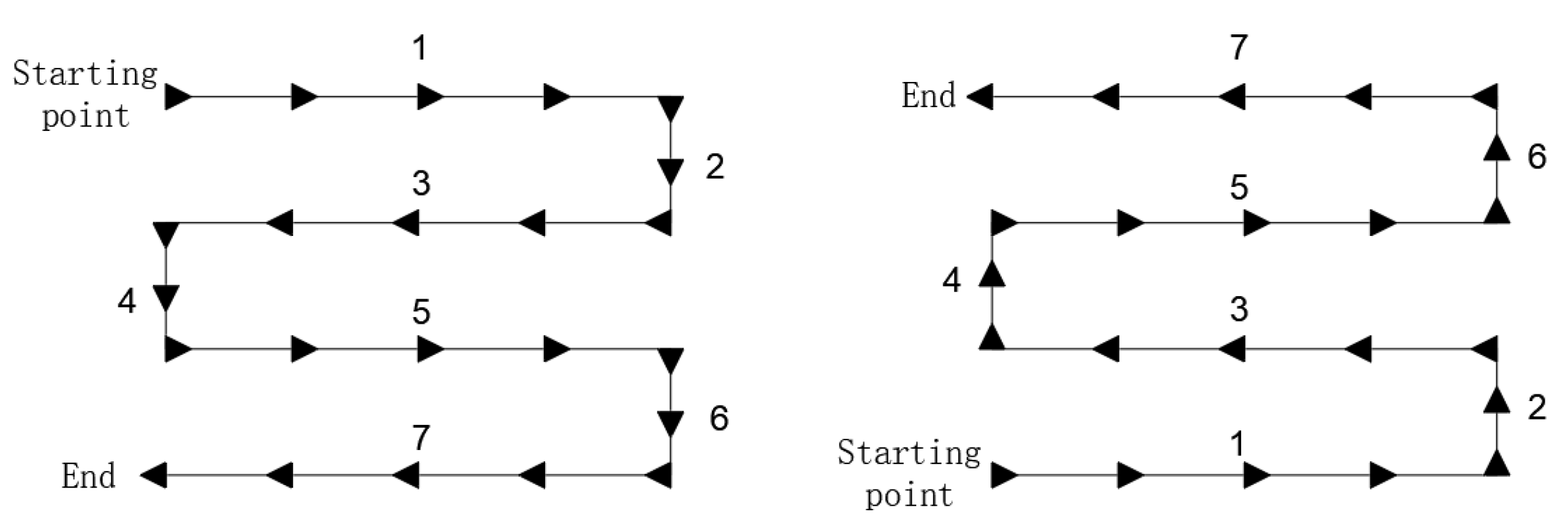
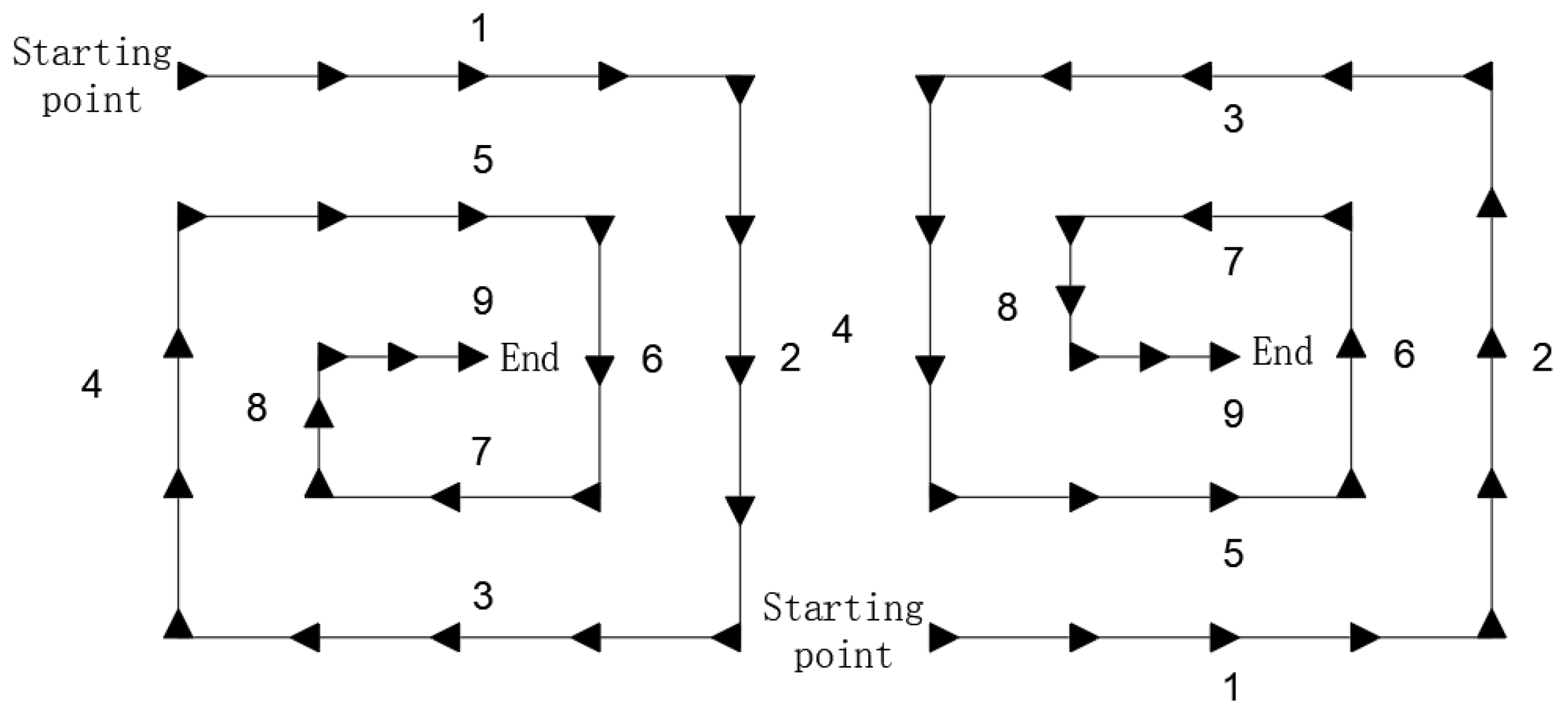
3.2.2. Determination of Inflection Point of Cutting Path

Taking a rectangular roadway as an example, the cutting paths mainly included “snake” and “loop” cutting paths [23], as shown in Figure 4 and Figure 5 below. The numbers 1–9 in the figure represent the cutting sequence, 1 represents the first cutting, and 9 represents the ninth cutting.
The inflection point position of the cutting path determined the formation quality and boundary shape of the cutting section [24]. Taking the “snake” cutting path of a rectangular section from bottom to top as an example, the inflection point of the path was determined to realize the accurate planning and control of the cutting path. The inflection point of the “snake” cutting path of the rectangular section from bottom to top is shown in Figure 6. In the figure, L is the cutting step size (should be less than 2ri), h upper 0 and h lower 0 are the ordinates of the upper and lower boundaries of the roadway, z upper 0 and z lower 0 are the ordinates of the center of the cutting head when cutting the upper and lower boundaries, and b right is the abscissa of the right boundary of the roadway.
The ordinates of all inflection points were:
z 2 n + 1 0 = z 2 n + 2 0 = z lower 0 + nL
When the cutting head was cutting the upper boundary, and φ = 0 in formula (18c):
z i 0 = sin θ 2 r i cos θ 2 ( ar i 2 + c ) + d 1 cos θ 2 ( d + d 3 ) d 4 cos θ 2 + a 2 sin θ 2
When the cutting head was cutting the lower boundary, and φ = π in formula (18c):
z i 0 = sin θ 2 r i cos θ 2 ( ar i 2 + c ) + d 1 cos θ 2 ( d + d 3 ) d 4 cos θ 2 + a 2 sin θ 2
Substituting the ordinates of the upper and lower boundaries into Equations (20) and (21), their corresponding θ2 angles can be obtained, and the corresponding ordinates of the center of the cutting head ( z upper 0 and z lower 0 ) can be calculated from Equation (6). At this time, the ordinates of inflection points 1, 2, 7 and 8 can be obtained.
Because the abscissa of the inflection point was symmetrical, we only discussed the situation when the cutting head cut the right boundary. Substituting φ = π 2 into Equation (18b), we can obtain:
y i o = cos θ 1 r i + sin θ 1 sin θ 2 ( ar i 2 + c ) + a 1 sin θ 1 + ( d + d 3 + d 4 ) sin θ 1 sin θ 2 +   a 2 cos θ 2 sin θ 1
The transverse coordinate of the rectangular right boundary ( b right ) and the cantilever vertical pendulum angle (θ2) when the cutting head cut the upper and lower boundaries were substituted into Equation (22). In addition, the abscissa of inflection points 2 and 7 were then calculated from Equation (6). According to the symmetry, the abscissa of inflection points 1 and 8 could be obtained. Finally, the ordinates of inflection points 3~6 could be calculated according to Equation (19). At this time, the coordinates of all inflection points have been obtained.

4. Simulation Results and Discussion

According to the dimensions of relevant structures of the EBZ-200 roadheader and substituting it into the space pose model of the above roadheader, MATLAB software was used to simulate the limit cutting section of the cutting head and the cutting path of the given rectangular roadway section, as shown in Figure 7, Figure 8 and Figure 9. In the simulation, the diameter of the cutting head was 1000 mm, the expansion of the cutting head was 0~500 mm, the cutting depth was 600 mm, and the cutting step length was 600 mm.
According to the simulation results in Figure 7, Figure 8 and Figure 9, the traversal process of the discrete points of the cutting head can be intuitively displayed. The boundary around the roadway is regular and smooth, and the shape of the limit cutting section is a waist drum. It can be seen from Figure 7 and Figure 8 that, when the cutting head does not extend, the cutting section of the roadway is 3280 mm × 3268 mm, and when the cutting head extends 500 mm, the cutting section of the roadway is 4100 mm × 3897 mm. It could be known that the longer the cutting head extended, the larger the cutting section was. Properly extending the cutting head is conducive to increasing the cutting area.
It can be seen from the simulation results in Figure 9 (at this time, the expansion and contraction of the cutting head is 0 mm, and the set cutting section is 3280 mm × 3200 mm), the cutting errors of the two sides of the roadway and the roof and floor are controlled within 1 mm. Compared with the traditional method [25,26] of determining the inflection point by subtracting the cutting head radius from the boundary position and the cutting control molding method adopted in document [27], the method adopted in this paper not only makes the cutting path consistent with the set cutting path, but also greatly improves the cutting accuracy and realizes high-precision planning and control of the cutting path.
Although the established cutting space position and posture coordinate system of the roadheader and the proposed cutting trajectory planning and control method of the roadheader took the rectangular section “snake” cutting technological path as an example, they were still applicable to the cutting technological path planning and control of the rectangular section “loop” and trapezoidal section roadways.

5. Conclusions

(1)
According to the robot theory and the principle of homogeneous coordinate transformation, the space pose model and space pose coordinate system of the roadheader were established, the connecting rod parameters of each working device of the roadheader were given, and the space pose transformation matrix of the roadheader and the space pose equation of the cutting head of the roadheader were derived. It provides a mathematical model and theoretical basis for the research of an autonomous cutting control system.
(2)
The problems of the forward kinematics of the space positioning of the cutting head of the roadheader and the inverse kinematics of the trajectory planning and control of the cutting head were summarized, and the forward kinematics and inverse kinematics were solved. It provides the kinematic theoretical basis for an autonomous cutting control system.
(3)
The cutting head model was established, and the spatial pose equation of the pick was derived and combined with the cutting process path of a rectangular roadway to determine the inflection point position coordinates of the cutting process path of a rectangular roadway. The method of trajectory planning and control is provided for an autonomous cutting control system
(4)
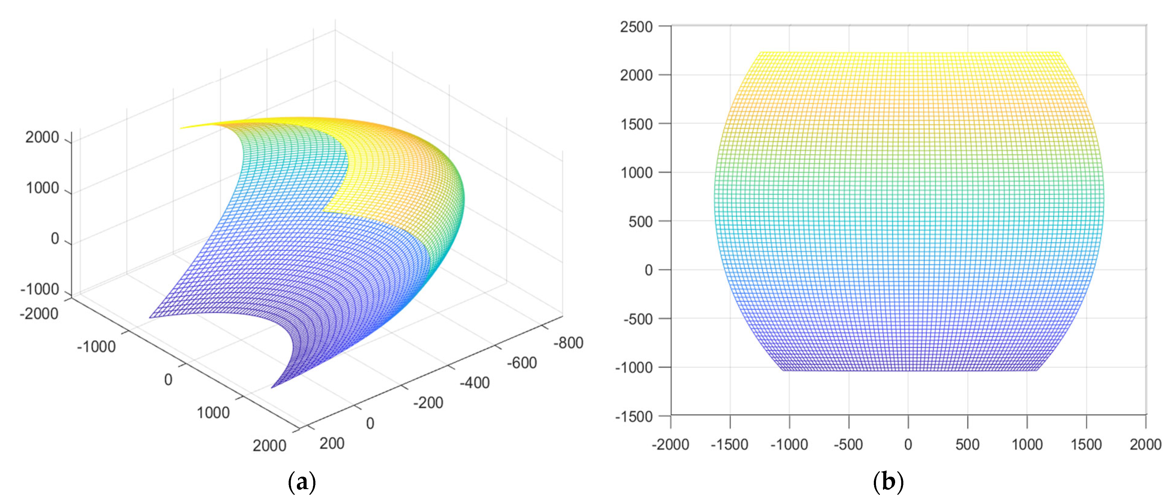
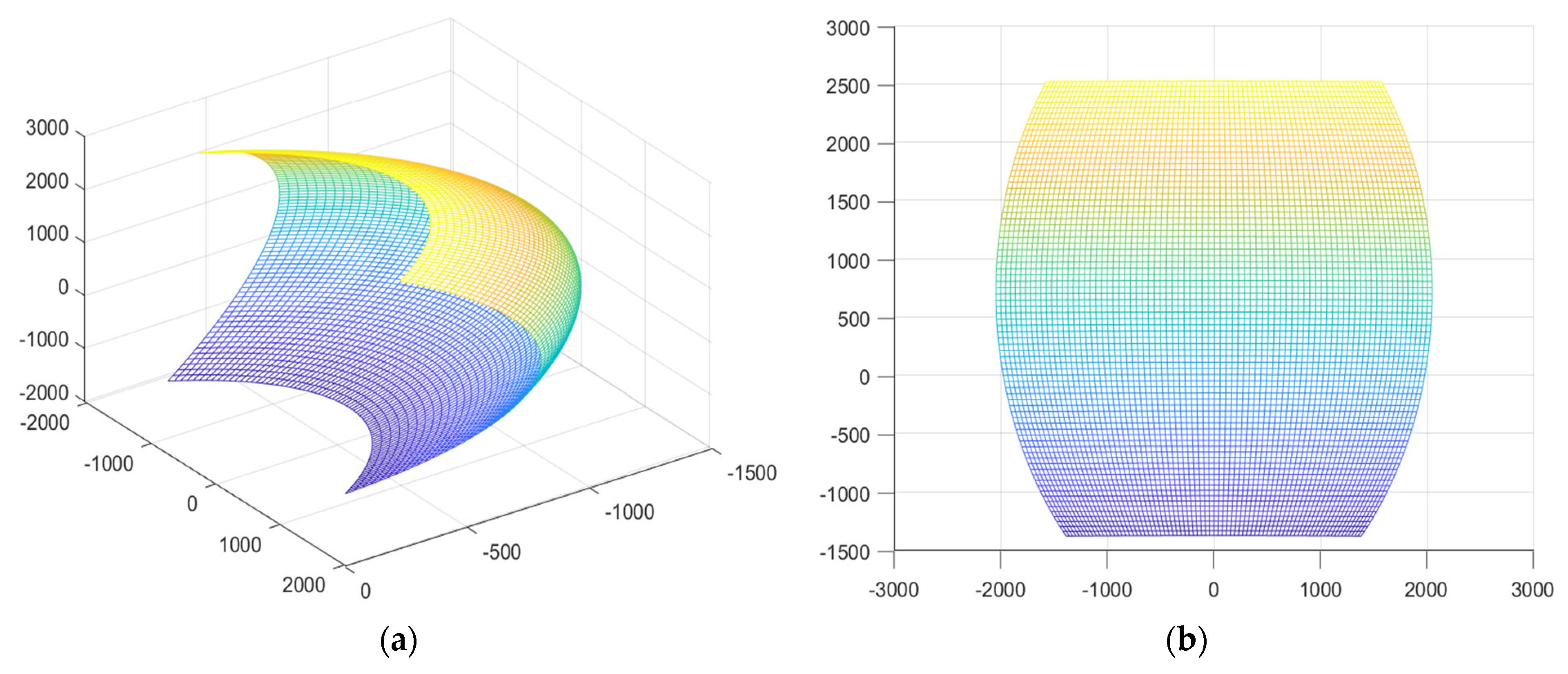
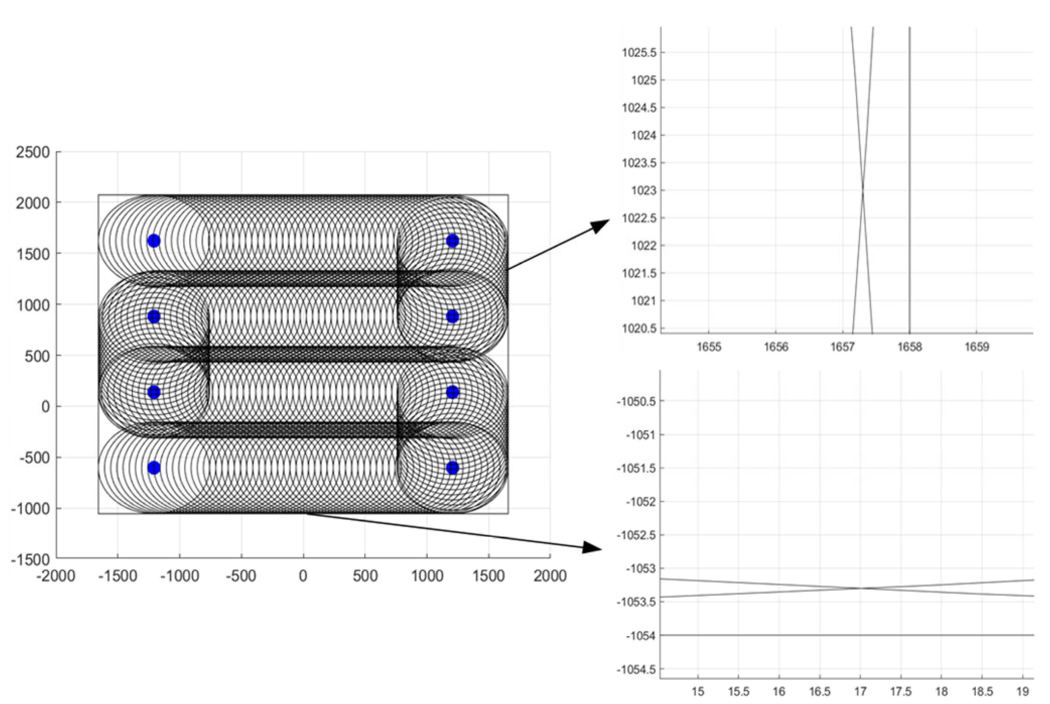
Taking an EBZ-200 roadheader as an example, MATLAB software was used to simulate the limit cutting area and cutting process path of the cutting head. The simulation results showed that the limit cutting section was a bulging waist shape, the boundary around the roadway was flat, and the roadway cutting error was controlled within 1 mm, which verified the reliability and effectiveness of the autonomous cutting theory of the roadheader. It lays a mathematical model and theoretical foundation for the realization of “autonomous operation of unmanned tunneling equipment”.

Author Contributions

Z.X., M.L., X.F. and G.W. designed the study and experiment; Z.X., M.L. and N.C. collected the data; Z.X., G.W., N.C. and Y.S. conducted the data analysis; Z.X., M.L. and X.F. provided the statistical methods; Z.X., M.L., N.C. and Y.S. drafted the paper; Z.X., M.L. and G.W. edited the paper. All authors have read and agreed to the published version of the manuscript.

Funding

This research was funded by the National Natural Science Foundation of China (Nos.51874276, 52004273 and 52104167), the Natural Science Foundation of Jiangsu Province (No. BK20200639), the Fundamental Research Funds for the Central Universities (No. 2020ZDPY0209) and the Open Competition Mechanism to Select the Best Candidates Fundation of Shanxi Province (No. 20201101005).

Data Availability Statement

All data and code used or analyzed in this study are available from the corresponding author on reasonable request.

Conflicts of Interest

The authors declare no conflict of interest.

References

  1. Milici, R.C.; Flores, R.M.; Stricker, G.D. Coal resources, reserves and peak coal production in the United States. Int. J. Coal Geol. 2013, 113, 109–115. [Google Scholar] [CrossRef]
  2. Xie, Z.; Zhang, N.; Qian, D.; Han, C.; An, Y.; Wang, Y. Rapid Excavation and Stability Control of Deep Roadways for an Underground Coal Mine with High Production in Inner Mongolia. Sustainability 2018, 10, 1160. [Google Scholar] [CrossRef]
  3. Kang, H.P. Sixty years development and prospects of rock bolting technology for underground coal mine roadway in China. J. China Univ. Min. Technol. 2016, 45, 1071–1081. [Google Scholar]
  4. Ning, S.; Su, H.; Gao, J. Research on Automatic Section Precision Forming of Boom-type Roadheader; Atlantis Press: Amsterdam, The Netherlands, 2015. [Google Scholar]
  5. Fang, L.; Liu, Z.; Wu, M. Intelligent Optimal Control Considering Dynamic Posture Compensation for a Cantilever Roadheader; Cambridge University Press: Cambridge, UK, 2022; pp. 583–598. [Google Scholar]
  6. Liu, Z.; Wang, S.; Xie, M.; Xue, C. Analysis of the Outer Contour Characteristics of Roadway Forming under the Influence of Cutting Head Vibration. Shock Vib. 2021, 2021, 6667523. [Google Scholar]
  7. Jie, T.; Wang, S.; Miao, W. Kinematic models and simulations for trajectory planning in the cutting of Spatially-Arbitrary crosssections by a robotic roadheader. Tunn. Undergr. Space Technol. 2018, 78, 115–123. [Google Scholar]
  8. Dolipski, M.; Cheluszka, P.; Sobota, P. Investigating the simulated control of the rotational speed of roadheader cutting heads, relating to the reduction of energy consumption during the cutting process. J. Min. Environ. 2015, 51, 298–308. [Google Scholar] [CrossRef]
  9. Wang, S.B.; Gao, F.; Li, R. Auto-cutting and shaping control system of arbitrary roadway section based on PCC. J. China Coal Soc. 2013, 38, 261–266. [Google Scholar]
  10. Zhao, X.L.; Du, X.Y.; Qu, X.B.; Li, W.T. Research on automatic deviation correction technology of cantilever roadheader. Coal Min. Mach. 2010, 31, 58–65. [Google Scholar]
  11. Liu, G.; Mu, D.S.; Duan, S.X.; Song, D.C. Design parameters optimization of cutting head of cantilever roadheader based on genetic algorithm. Appl. Mech. Mater. 2012, 215–216, 193–196. [Google Scholar] [CrossRef]
  12. Zhai, Y.P. Research on Deviation Compensation Strategy of a New Four DOF Attitude Adjustment Mechanism. Ph.D. Thesis, Tianjin University, Tianjin, China, 2015. [Google Scholar]
  13. Zhang, M.J.; Cai, X.H.; Lv, F.Y.; Zong, K.; Wu, M. Research on self-correction of grid type roadheader in confined tunnel space. J. Instrum. 2018, 39, 62–70. [Google Scholar]
  14. Zh, M.J.; Lu, F.Y.; Fu, S.H.; Zong, K.; Wu, M. Study on the pitch angle control of a robotized hydraulic roadheader using different control methods. J. Mech. Sci. Technol. 2018, 32, 4893–4901. [Google Scholar]
  15. Ding, X.L.; Zhou, L.L.; Zhou, J. Analysis method of space pose deviation of robot. J. Beijing Univ. Aeronaut. Astronaut. 2009, 35, 241–245. [Google Scholar]
  16. Wang, S.; Gao, F.; Gao, J.; Li, R.; Wu, M. Research on Automatic Cross Section Cutting and Forming Control in Coal Mine Underground Based on Oil Cylinder Stroke Sensor and PCC Electrical Control System; ASME Press: New York, NY, USA, 2011. [Google Scholar]
  17. Tuncer, A.; Yildirim, M. Dynamic path planning of mobile robots with improved genetic algorithm. Comput. Electr. Eng. 2012, 38, 1564–1572. [Google Scholar] [CrossRef]
  18. Yu, L.; Dan, H.; Xiao, C.; Zhi, J.; Hao, M. Study on Supporting Equipment Selection for Cantilever Roadheader in Metal Mine. Min. Res. Dev. 2022, 42, 6. [Google Scholar]
  19. Ning, L.; Zhao, Y. Key Technology and Integration Method Based on LAN of Cantilever Machine Digital Design. Coal Technol. 2016, 35, 234–236. [Google Scholar]
  20. Mao, J.; Li, J.G.; Li, W.K.; Yong, H.Z. Kinematics analysis and simulation of profiling memory cutting for tunnel robot in complex environment. Procedia Earth Planet. Sci. 2009, 1, 1411–1417. [Google Scholar]
  21. Tian, J. Research on Boom-Type Roadheader Auto Cutting and Profiling Control System; China University of Mining and Technology: Beijing, China, 2010. [Google Scholar]
  22. Wang, S. Research on Memory Cutting and Roadway Border Control Method of Boom-Type Roadheader; China University of Mining and Technology: Beijing, China, 2014. [Google Scholar]
  23. Hu, C.; Zhang, Y.; Yu, R.; Fang, X.; Xu, Z.; Wang, L.; Zhao, B. Research on the Optimization of Cutting Path of Cantilever Roadheader in Large Section Excavation. Sustainability 2022, 14, 5345. [Google Scholar] [CrossRef]
  24. Dandan, G. Research on Profiling Cutting Theory of Longitudinal Axis Type Roadheader; Liaoning Technical University: Fuxin, China, 2007. [Google Scholar]
  25. Shi, Z.; Zhong, N. Application of MATLAB in Boom-type Roadheader Auto Profiling Control Research. Coal Min. Mach. 2005, 11, 90–92. [Google Scholar]
  26. Jia, C.; Zhi, Z.; Hai, D. Matlab Simulation of Cutting Intelligent Control of Cantilever Roadheader. Min. Technol. 2007, 3, 38–39. [Google Scholar]
  27. Jie, T.; Su-Yu, W.; Jing, M.; Miao, W. Spatial pose kinematics model and simulation of boom-type roadheader. J. China Coal Soc. 2015, 40, 2617–2622. [Google Scholar]
Figure 1. Space pose model of roadheader.
Energies 15 06190 g001
Figure 2. Schematic diagram of heading machine pose parameters.
Energies 15 06190 g002
Figure 3. Simplified model diagram of the cutting head.
Energies 15 06190 g003
Figure 4. A “snake” cutting path track diagram.
Energies 15 06190 g004
Figure 5. A “loop” cutting path track diagram.
Energies 15 06190 g005
Figure 6. Inflection point diagram of the “snake” cutting path of a rectangular roadway.
Energies 15 06190 g006
Figure 7. Simulation diagram of limit cutting section of the cutting head (d = 0 mm). (a) Three-dimensional simulation diagram of cutting section. (b) Projection of cutting section on YOZ plane.
Energies 15 06190 g007
Figure 8. Simulation diagram of limit cutting section of the cutting head (d = 500 mm). (a) Three-dimensional simulation diagram of cutting section. (b) Projection of cutting section on YOZ plane.
Energies 15 06190 g008
Figure 9. Simulation diagram of rectangular roadway design cutting path.
Energies 15 06190 g009
Table 1. Difference between standard D-H parameter method and modified D-H parameter method.
Standard D-H Parameter MethodModified D-H Parameter Method
1. The fixed coordinate system of the connecting rod is different.
Takes the latter joint coordinate system of the connecting rod as the fixed coordinate system.Takes the previous joint coordinate system of the connecting rod as the fixed coordinate system.
2. The x-axis direction of the connecting rod coordinate system is determined in different ways.
The x-axis direction is determined by the cross-multiplication of the current z-axis and the z-axis of the “previous” coordinate system.The x-axis direction is determined by the cross-multiplication of the z-axis of the “next” coordinate system and the current z-axis.
3. The transformation rules between connecting rod coordinate systems are different.
The order of parameter changes between adjacent joint coordinate systems is: θ→d→ a →αThe order of parameter changes between adjacent joint coordinate systems is: α→ a →θ→d
T i i 1 = Rot ( Z i 1 , θ n ) · Trans ( Z i 1 , d i )
Trans ( X i , a i ) · Rot ( X i , α i )
T i i 1 = Rot ( X i 1 , α i 1 ) · Trans ( X i 1 , a i 1 )
Rot ( Z i , θ i ) · Trans ( Z i , d i )
Table 2. Parameter table of cutting head connecting rod.
Connecting Rod i ai−1αi−1diθi
1a0d1θ1
2a190°0θ2
3a290°d3 + d0
40d40
Publisher’s Note: MDPI stays neutral with regard to jurisdictional claims in published maps and institutional affiliations.

