Article

Displacement Characteristics and Produced Oil Properties in Steam Flood Heavy Oil Process

1
Research Institute of Exploration and Development, Liaohe Oilfield Company, PetroChina, Panjin 124010, China
2
National Energy Heavy Oil Exploitation R & D Center, Panjin 124010, China
3
State Key Laboratory of Heavy Oil Processing, China University of Petroleum, Beijing 102249, China
4
State Key Laboratory of Petroleum Resources and Prospecting, China University of Petroleum, Beijing 102249, China
*
Author to whom correspondence should be addressed.
Energies 2022, 15(17), 6246; https://doi.org/10.3390/en15176246
Submission received: 9 July 2022 / Revised: 7 August 2022 / Accepted: 14 August 2022 / Published: 27 August 2022
(This article belongs to the Special Issue Oil Field Chemicals and Enhanced Oil Recovery)

Abstract

:
Thermal recovery is one of the most effective techniques for viscous oil production, which has been widely used in the heavy oilfield development. The mechanisms and percolation characteristics of thermal recovery have attracted a lot of attention. However, the displacement characteristics and produced oil properties in the steam flood heavy oil process are rarely addressed. In this paper, steam flooding experiments with two heavy oil viscosities under the temperatures from 120 to 200 °C and velocities from 1 to 3 mL/min were carried out to examine the oil displacement efficiency and the produced oil properties. The results show that the majority of the oil is produced in the low water cut stage. Temperature increment is helpful for prolonging the water breakthrough time. The high injection velocity of steam contributes to a high recovery factor, even if it enters into the high water cut stage. The rheology of the produced oils severely changes because the SARA composition changes, and emulsification occurs during the steam flooding heavy oil process. With the increasing steam temperature, the relative content of resins in the produced oils decreases, and asphaltenes increase. With the increase in the injection volume and the injection velocity of steam, the content of resins and asphaltenes increases. This leads to an increment in the produced oil viscosities. The effect of injection velocity on the rheology properties of the produced oils increases with temperature increment. The finding of this work will provide the technical support for heavy oilfields development.

1. Introduction

Heavy oil resource accounts for 70% of the original oil in place (OOIP) and is widely distributed worldwide [1]. In China, heavy oil yields more than four million tons per year [2]. Xinjiang, Liao He and Sheng Li oilfields are the three major developed production areas of heavy oil in China, which, respectively, feature geological reserves of 1.2 billion tons, 120 million tons and 520 million tons of oil [3,4]. As one of the effective techniques for heavy oil production, steam is widely used in these heavy oilfield developments [5].
Steam flooding is one of the thermal recovery methods, which requires an oil layer thickness of 10–60 m, initial oil saturation of more than 40%, reservoir burial depth of less than 1400 m and crude oil viscosity of less than 10,000 mPa s [6]. High temperature steam is continuously injected from the injection well to the flood heavy oil in the production well. The mechanisms of the steam flooding process mainly include the energy supplement induced by steam expansion [7], viscosity reduction by heating the formation with high temperature steam [8] and increase in the percolation capacity of heavy oil [9]. Steam distillation of light components has been proven to reduce the interfacial tension and increase the percolation capacity of heavy oil [10]. Steam with a different temperature and velocity can emulsify with heavy oil and form emulsion to improve oil recovery [11].
Mechanism research plays an important role in many studies of the steam flooding process. Reducing the heat loss, delaying the steam breakthrough time and increasing the sweep area are three key issues for heavy oil development. In recent years, there have been some new steam flooding technologies, such as steam-assisted gravity drainage (SAGD), which makes use of O/W gravity differentiation [12], solvent-assisted steam flooding, which makes use of the thermal insulation and resistance of the auxiliary solvent, and horizontal fractured well auxiliary steam flooding, which relies on the fracture network and other means formed by fracturing [13]. The percolation characteristics of heavy oil play an important role in the steam flooding process of heavy oil [14]. Many studies show that the relationship between the pressure gradient and percolation velocity is not linearly dependent. The starting pressure gradient is the threshold of single-phase oil percolation [15]. Heavy oil starts to flow only when the flooding pressure gradient exceeds the initial starting pressure gradient. Many studies have shown that the initial starting pressure gradient of heavy oil is not only affected by reservoir characteristics, such as the porosity, permeability and temperature, but also by the composition and viscosity of crude oil [16].
Although the field test of heavy oil steam flooding has achieved good results, the flooding characteristics and component changes of heavy oil are still unclear. In this paper, steam flooding experiments of heavy oil were carried out by considering different temperatures, injection velocities, oil viscosities and core permeability. The rheology property and SARA composition of the produced oils were analyzed, which can reveal the flooding characteristics during steam flooding.

2. Materials and Experiments

2.1. Materials

Two heavy oils (Sample A and Sample B) were obtained from the Liaohe oilfield in China, with a viscosity of 2990 mPa·s and 7128 mPa·s and at reservoir temperature (60 °C). The formation water of the oilfield was used as the experimental brine, whose ion composition is shown in Table 1. All experiments were prepared using this brine. The experimental water was field-filtered formation water with a salinity of 10,486 mg/L.

2.2. Core Steam Flooding Experiments

Artificial sandstone cores with a length of 30 cm, width of 4.5 cm and height of 4.5 cm were used to mimic the porous media in the steam flooding experiments. The artificial cores were fabricated according to our patents and widely used in the laboratorial experiments [17,18,19,20]. A total of 8 core flooding experiments were conducted by considering various temperatures, oil viscosities, permeability and injection velocities. The core physical properties and experimental schemes are shown in Table 2.
The nitrogen flow velocity and pressure difference were recorded and used to calculate the gas phase permeability of the core by using the Darcy formula. The core was loaded into the high-temperature-resistant core holder and vacuumed for 12 h. Then, the core was saturated with the experimental water, and the water phase permeability was measured. The experimental water was pumped into the core holder at a constant velocity. The pressure and flow velocity were recorded at a stable pressure difference, and the water phase permeability was calculated by using the Darcy formula. At last, the saturated core was flooded with crude oil to create the irreducible water saturation. The core holder was put in a thermostat, which was set at 60 °C for 24 h of aging. Further, the steam was injected to the core holder by the steam generator. The produced liquid was collected in test tubes, and the injection pressure was recorded by the pressure sensor. Experiments were ended when the water cut reached 98%. The volumes of oil and water were read, respectively, after oil and water were separated completely. Figure 1 shows the schematic diagram for the steam flooding experiment. In the process of steam flooding, the produced oils can be divided into three stages, according to the different water cuts: no water cut (fw = 0), low water cut (fw < 0.8) and high water cut (fw > 0.8).

2.3. Rheological Property Test

The rheology of crude oil and the oils produced in different stages were tested by using an MCR 302e Anton Par rheometer. The shear velocity and test temperature were set at 0–200 s−1 and 60 °C, respectively.

2.4. SARA Fractionation

The crude oil and the oils produced in different water flooding stages were first dehydrated with anhydrous sodium sulfate and then separated into saturates, aromatics, resins and asphaltenes (SARA) based on the Chinese industry standard NB/SH/T 0509-2010 method.
Briefly, about 1 g of oil sample was dissolved in 50 mL of n-heptane. The mixture was heated to reflux for 1 h and then stored in the dark for 2 h after cooling. The n-heptane precipitation was obtained by filtration using a quantitative filter paper. The filter paper with precipitation was put into the extractor and heated to reflux for 1 h by using the n-heptane mixture until the solvent was colorless. The n-heptane soluble fraction, which was named maltene, was obtained by a vacuum rotary evaporation of the n-heptane mixture. The filter paper with precipitation in the extractor was heated to reflux for 1 h by using 30 mL of toluene until the solvent was colorless. Asphaltenes were obtained by a vacuum rotary evaporation of the toluene mixture. The maltene in the n-heptane was concentrated to about 5 mL. A glass column (50 mm inner diameter × 700 mm length) was packed with 40 g of neutral alumina adsorbent (100−200 mesh, activated at 450 °C for 6 h, with 1 wt% water added) in a 50 °C circulating water bath. Then, maltene was added on top of the neutral alumina adsorbent in the glass column. Saturates and aromatics were eluted with 80 mL of n-heptane and 80 mL of toluene, respectively. A total of 40 mL of 50:50 (v/v) toluene/ethanol mixture, 40 mL of toluene and 40 mL of ethanol were added sequentially to elute the resins. The solvent in each effluent was dried in a vacuum drying oven (110 °C, 0.08 Mpa of vacuum) and weighed several times after cooling.

3. Results and Discussion

3.1. Steam Flooding Characteristics Analysis

By changing the temperature and injection velocity of steam, the physical simulation experiments of steam flooding were carried out for two heavy oils with a different viscosity and two cores with a different permeability. The flooding characteristics during the steam flooding heavy oil process were studied, including recovery, water cut, pressure and the ratio of recovery.

3.1.1. Temperature Effect of Injected Steam

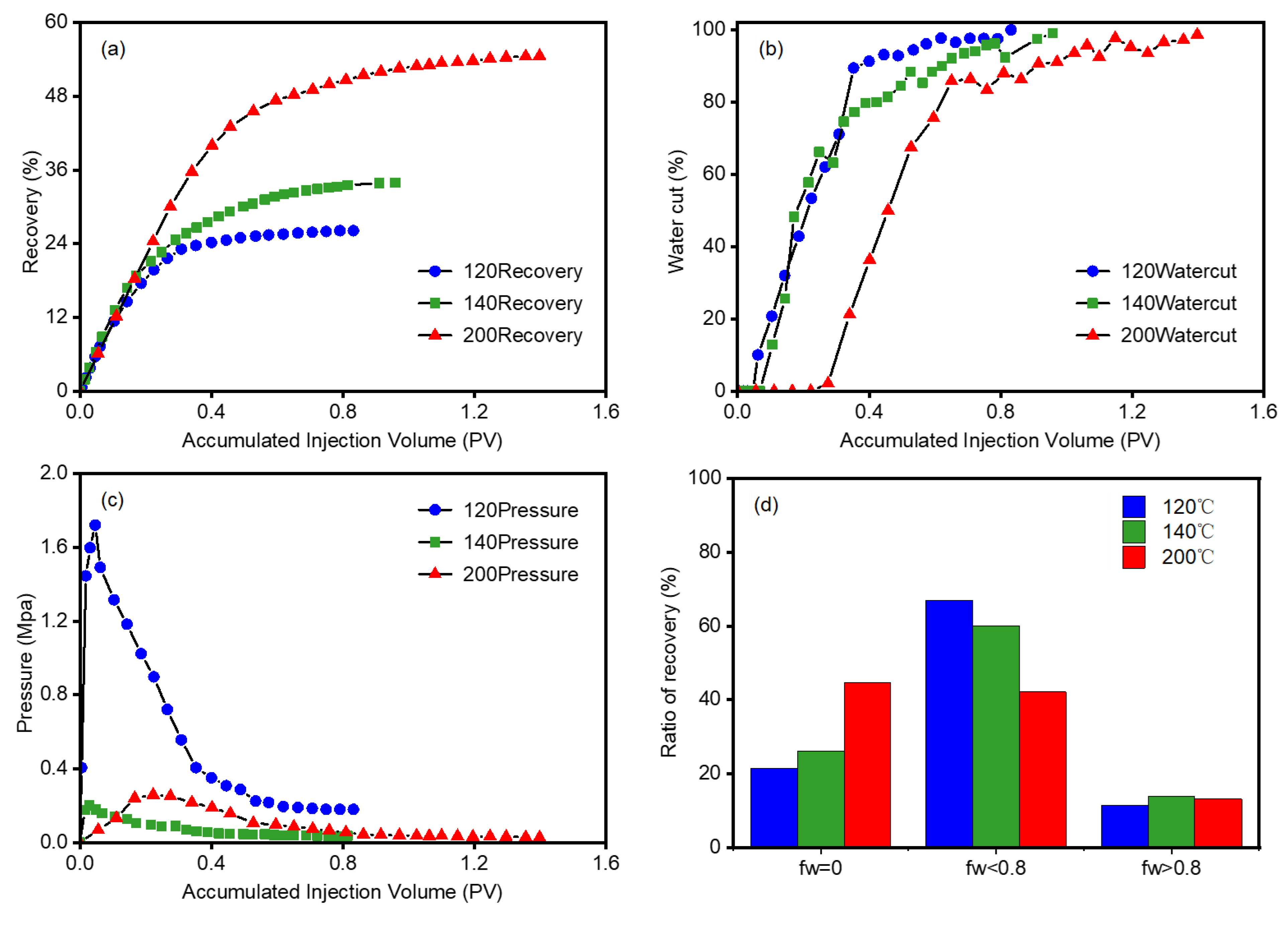
Under the permeability of 4000 mD, the flooding characteristics of heavy oil (Sample A) with steam at 120 °C, 140 °C and 200 °C at 1 mL/min were compared to study the influence of temperature. The recovery curves at different temperatures are shown in Figure 2a. When the steam temperature increases from 120 °C to 140 °C, the recovery increases from 26.1% to 33.9%, and the recovery increases by 7.8%. The temperature was raised to 200 °C, and the recovery was increased to 54.6%, which further increased by 20.7%. High steam temperatures result in a low viscosity of the heavy oil, which can improve the flow capacity by decreasing the initial threshold pressure. The curves of the water cut are shown in Figure 2b. High temperature leads to a long no water cut stage, which delays the high water cut stage. Therefore, the oil recovery would be significantly improved by increasing the steam temperature. Under the conditions of 120 °C and 140 °C, the water breakthrough time is nearly the same because the temperature difference between the steam and the formation is small. The viscosity reduction effect of heavy oil is lower than that at 200 °C, and the higher O/W flow ratio produces a serious viscous finger phenomenon. At the same time, the percolation capacity of the water phase is poor, leading to the water phase breakthrough and recovery reduction. The water cut curve of each temperature is not a smooth rising curve; the water cut varies to different degrees after the water phase breakthrough. The results show that the heavy oil in the core is heated continuously; the heavy oil will flow with the expansion of the steam chamber in the steam flooding heavy oil process. High temperature increases the oil’s flow ability and recovery.
The pressure curves are shown in Figure 2c. The maximum injection pressure is 1.72 Mpa at 120 °C, 0.21 Mpa and 0.26 Mpa at 140 and 200 °C, respectively. At the same time, the temperature exceeds the abnormal temperature of heavy oil, which should result in the viscosity reduction in heavy oil. The lower threshold pressure will lead to a decrease in the flooding pressure difference. The smaller pressure difference also indicates good mobility. The ratio of recovery in different flooding stages is shown in Figure 2d. At 120 °C, the recovery factor in no water cut, low water cut and high water cut stages is 21.5%, 67.0% and 11.5%. At 140 °C, the recovery factors are 26.1%, 60.7% and 13.8%. Additionally, at 200 °C, recovery factors are 44.7%, 42.1% and 13.2%. This shows that the temperature of the steam injection mainly affects the recovery in the no water cut and low water cut stages. High temperature results in an increase in the ratio of recovery in the no water cut stage and a decrease in the recovery factor in the low water cut stage.

3.1.2. Velocity Effect of Injected Steam

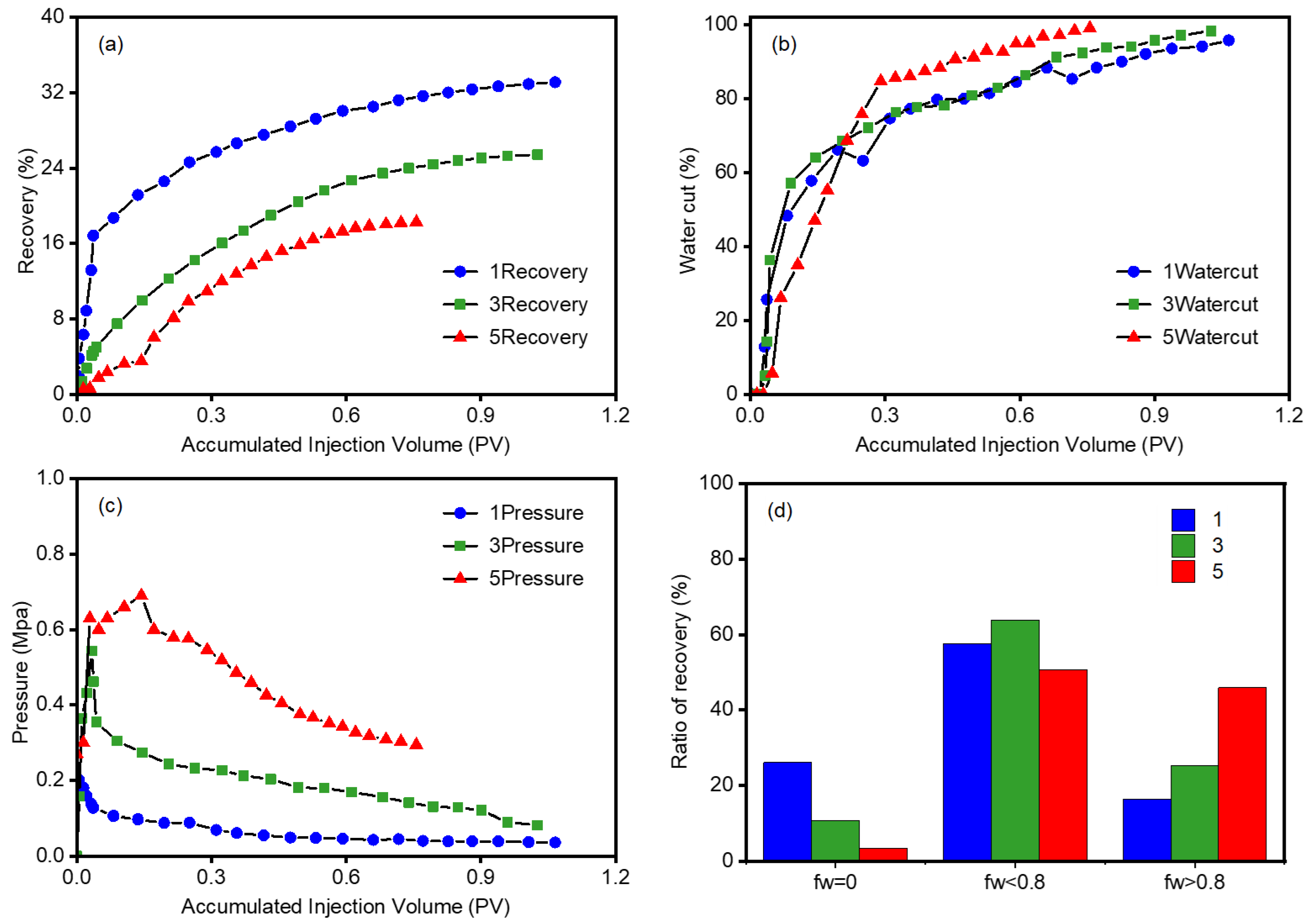
The effects of three injection velocities of 1 mL/min, 3 mL/min and 5 mL/min on the flooding characteristics during the heavy oil steam flooding process at 140 °C and 4000 mD permeability were compared and analyzed. The recovery curves of the steam flooding at different injection velocities are shown in Figure 3a. When the injection velocity increases from 1 mL/min to 3 mL/min and 5 mL/min, the recovery of steam flooding decreases from 33.9% to 25.4% and 18.3%. When the injection velocity is too high, the flow of the oil phase in the core is hindered by the water and gas phases, which inhibits the flow of the oil phase and tends to produce gas channeling, resulting in a reduced recovery. In addition, the lower the steam injection velocity, the slower the heat transfer of steam in the core migration process. As the injection velocity increases, the recovery of steam flooding decreases. The water cut curves are shown in Figure 3b. The high injection velocity results in a fast water breakthrough. With steam flooding at a velocity of 1 mL/min and 3 mL/min, the water phase breakthrough occurs when the injection volume reaches 0.07 PV and 0.03 PV. However, when the injection velocity reaches 5 mL/min, the water breakthrough time is 0.005 PV. When the injection velocity is 1 mL/min, the water phase has the latest breakthrough time and the slowest water cut rising velocity. This shows that increasing the injection velocity can delay the increase in water cut during the steam flooding process. High temperature steam heats the core to decrease the viscosity of heavy oil in the pores. High steam velocity causes the thermal connection in the core to form a dominant channel. The steam will be formed and continuously reduce the oil recovery of steam flooding after steam condensation.
The pressure curves are shown in Figure 3c. High injection velocity results in a higher pressure in the steam flooding process. The increase in the injection velocity will increase the flooding pressure difference, but the difference in viscosity between the heavy oil and steam leads to a reduced recovery because of the serious fingering phenomenon [21]. The pressure curves of the different injection viscosities are similar, and the high injection velocity results in the high maximum flooding pressure. After the water phase and steam breakthrough, the pressure decreases quickly in the late flooding period. The ratio of recovery in different steam flooding stages is shown in Figure 3d. As the injection velocity increases, the ratio of recovery in the no water stage is 26.1%, 10.8% and 3.4%. The increase in the injection velocity can reduce the ratio of recovery in the no water stage. The ratio of recovery in the low water cut stage is 57.7%, 63.8% and 50.6%. It can be seen that the low water cut stage is the main production stage during the steam flooding process. The ratio of recovery is 16.2%, 25.3% and 45.9% at the high water cut stage. The flow velocity mainly affects the no water cut and high water cut stages [22]. Although the increased injection velocity leads to an earlier water phase breakthrough, the higher injection velocity can provide a greater flooding force. A large amount of heavy oil can be recovered in the high water cut stage, which also accounts for a high ratio of recovery.

3.1.3. Comparison of Different Heavy Oil Viscosities

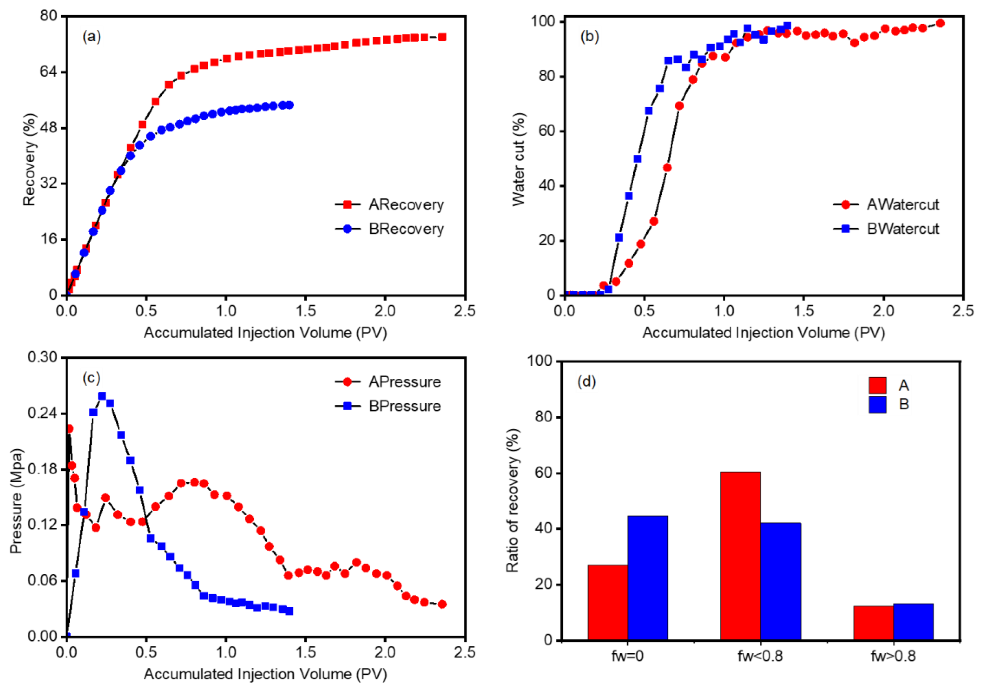
The steam flooding experiment was carried out at 4000 mD, 200 °C and 1 mL/min of steam, and the flooding characteristics of the two oils with different viscosities are analyzed. The recovery curves of heavy oils with different viscosities are shown in Figure 4a. The steam flooding recovery of the ordinary heavy oil (Sample A) is 30% higher than that of the super heavy oil (Sample B), indicating that the lower viscosity oil results in a higher recovery under the same steam flooding condition. The water cut curves are shown in Figure 4b. The heavy oil with high viscosity has a long no water cut stage because high viscosity can effectively prevent viscous fingering and prolong water breakthrough time. However, water and steam breakthrough quickly results in a rapid increase in the water cut and a decrease in recovery. Meanwhile, the water cut curve is not increased with the increase in recovery but fluctuates in the high water cut stage. High viscosity results in an obvious water cut fluctuation. The injection pressure curves are shown in Figure 4c. The maximum injection pressure of the super heavy oil is 0.25 mPa higher than that of the ordinary heavy oil, but the pressure drops rapidly in the later period. Pressure fluctuation occurs in the process of steam flooding ordinary heavy oil. The heavy oil under viscosity reduction by water and steam moves alternately in the formation [23], resulting in pressure fluctuation. The water cut increases rapidly in the flooding process of high viscosity oil, which mainly affects the no water cut stage and the low water cut stage. The ratio of recovery in the high water cut stage is basically unchanged, which is shown in Figure 4d. The lower the viscosity, the faster the water phase breaks through. The less oil is produced in the no water stage, and more oil is produced in the low water cut stage. In the high water cut stage, the steam sweep effect is basically unchanged because of the dominant water and steam channel formation. The viscosity of heavy oil has little influence on oil recovery in the high water cut stage.

3.1.4. Comparison of Different Coal Permeability

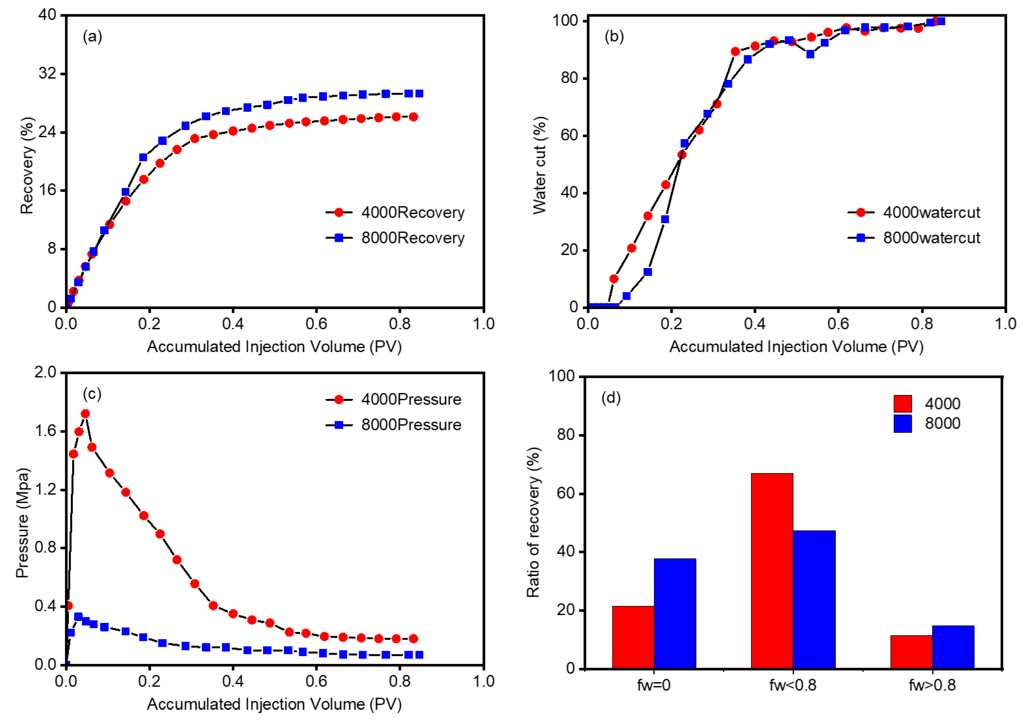
The flooding characteristics of two permeability cores (4000 mD and 8000 mD) of heavy oil (Sample A) were compared under the condition of 120 °C temperature and 1 mL/min velocity. The recovery curves of different permeability cores are shown in Figure 5a. The steam flooding recovery of the 8000 mD core is 3% higher than that of the 4000 mD core, indicating that the higher permeability results in a higher recovery under the same steam flooding condition. The water cut curves are shown as Figure 5b. Permeability does not affect the water breakthrough time, but it affects the increasing velocity of the water cut. The water cut’s increasing velocity of the low permeability core is higher than that of the high permeability core. The injection pressure curves are shown in Figure 5c. The maximum injection pressure of the low permeability core is 1.8 Mpa higher than that of the high permeability core, but the pressure drops rapidly in the later period. The ratio of recovery in different steam flooding stages is shown in Figure 5d. The ratio of recovery in the no water cut stage is 21.5% in the 4000 mD core and 37.8% in the 8000 mD core, respectively. The increase in permeability can enhance the ratio of recovery in the no water cut and high water cut stages. The ratio of recovery in the low water cut stage decreases from 67.0% to 47.5% with the increase in permeability.
The experimental results above showed the influence of the temperature of steam, the injection velocity of steam, the viscosity of heavy oil and the permeability of the core on the recovery, water cut, pressure and the ratio of recovery. It can be seen that the temperature of the steam injection mainly affects recovery in the no water cut and low water cut stages. Additionally, the injection velocity mainly affects the no water cut and high water cut stages. Viscosity changes mainly affect the water breaks through time. The lower the viscosity, the faster the water phase breaks through the core. The permeability mainly affects the no water cut and low water cut stages.

3.2. Rheology and SARA of Produced Oils Analysis

Rheological tests and SARA composition analysis [24] of the crude oil and the produced oils were performed at 140 °C and 200 °C, with the velocity of injection steam increasing from 1 mL/min to 5 mL/min.

3.2.1. Rheology Analysis

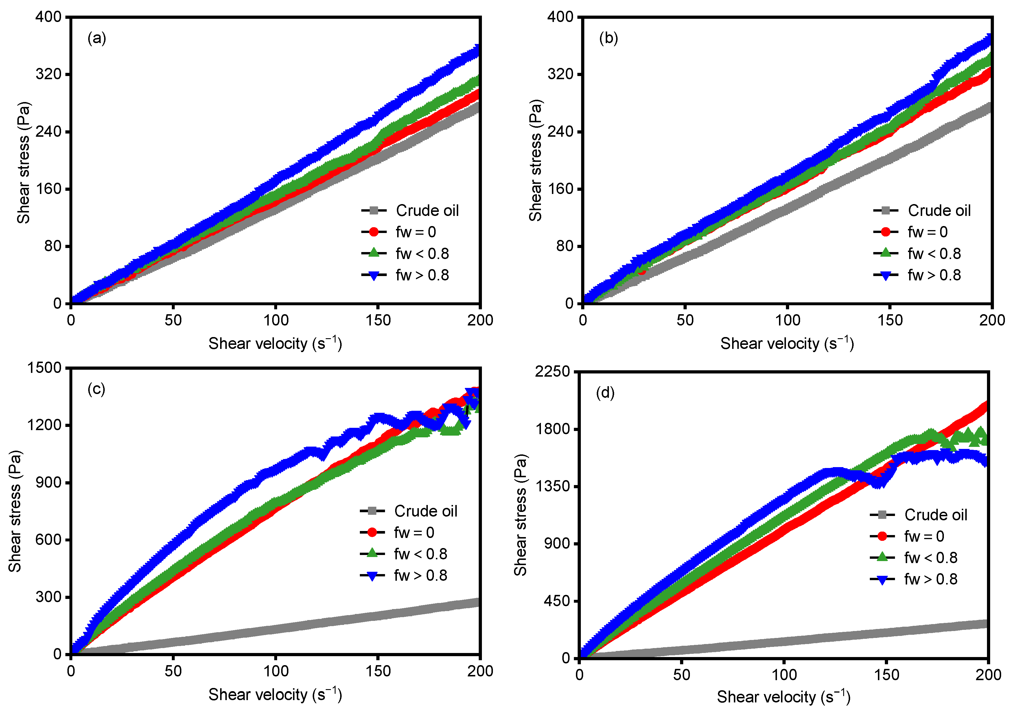
The rheology curves of the produced oils in different steam flooding stages at 140 °C and 1 mL/min velocity are shown in Figure 6a. The slope of the shear stress–shear velocity curve represents the viscosity of the produced oils. The produced oil exhibits Newtonian fluid characteristics during the steam flooding process. The viscosity of the produced oils in different stages is higher than that of the crude oil, indicating that the produced oils contain the W/O emulsion with the steam. The viscosity of the produced oils decreases in the order of high water cut stage, low water cut stage and no water cut stage, indicating that the viscosity of the produced oils gradually increases with the increase in the injection volume. The rheology curves of the produced oils in different stages at 140 °C and 5 mL/min velocity are shown in Figure 6b. The rheology of the produced oils is basically similar to that at 1 mL/min velocity. The increase in the injection velocity enhances the emulsification performance and causes a slightly increased viscosity of the produced oils. The rheology curves of the produced oils in different steam flooding stages at 200 °C and 1 mL/min velocity are shown in Figure 6c, and 5 mL/min is shown in Figure 6d. The produced oils show non-Newtonian fluid characteristics. The viscosity of the produced oil increases by forming the W/O emulsion between the oil and the steam with the increase in injection volume. The viscosity of the produced oil increases significantly when the injection velocity of the steam increases at 200 °C.
During the steam flooding process, the produced oils prefer to emulsify into the O/W emulsion with the steam. The increase in temperature contributes to the enhancement of emulsification and non-Newtonian characteristics of the produced oils. Compared with steam flooding at different injection velocities, the high velocity results in the strong shear action between the steam and the heavy oil. The injection velocity has an obvious influence on the high temperature.

3.2.2. SARA Composition Analysis

The data in Table 3 correlate the rheology properties of the produced oils and the content of the SARA composition. The viscosity of the heavy oil affects the recovery of the steam flooding. Therefore, the SARA composition of the crude oil and the produced oils in different stages has to be investigated. When the steam injection velocity is 1 mL/min at 140 °C, the relative content of saturates in the produced oils decreases, and the aromatics content is basically unchanged. Meanwhile, the relative content of resins and asphaltenes increases, resulting in the higher viscosity compared with that of the crude oil. Many studies have shown that the content of asphaltenes and resins promotes emulsification [25]. The increase in asphaltene and resin can improve the stability of the W/O emulsion, resulting in an increase in viscosity of the produced oils [26]. When the injection velocity increases, the asphaltene content increases with the injection volume increase. Compared to asphaltenes, the changes in the resins content in the three flooding stages are not obvious. This is due to the steam flooding of a large amount of asphaltenes under the influence of high temperature, resulting in a higher viscosity of the produced oil than the crude oil. At the same time, due to the different content of resins and asphaltenes in the heavy oils produced in three stages, there is also a difference between the viscosities of the produced oil [27]. The high water cut stage has the highest resins and asphaltenes content, which results in a higher viscosity of the produced oils [28]. Meanwhile, the no water cut stage has the lowest content of resins and asphaltenes, causing a lower viscosity of the produced oils. When the steam injection velocity is 1 mL/min at 200 °C, with the increase in the injection velocity, the content of saturates, resins and asphaltenes decreases, and the content of aromatics increases. The polar molecules of resins and asphaltenes in the produced oils increase, which is conducive to the formation of a stable emulsion, and the viscosity of the produced oil increases during the steam flooding process. At the same time, the content of the polar molecules increases with an increase in the injection volume.
When the steam injection velocity increases to 5 mL/min, with the increase in the injection volume, the asphaltenes content of the produced oils in different stages increases 1.86%, 3.08% and 3.71%, respectively. The heavy oil can be effectively used after being subjected to high temperature steam, thus forming a more stable W/O emulsion and greatly increasing the viscosity. The contents of aromatics and asphaltenes increase with the increase in temperature. The relative content of asphaltenes increases with the increase in injection velocity. The higher the temperature, the more obvious the effect of the injection velocity. With the increase in injection volume, the content of resins and asphaltenes increases, which contributes to the formation of an emulsion and a higher viscosity of the produced oils in different stages.

4. Conclusions

Steam flooding experiments with two heavy oil viscosities under the temperatures from 120 to 200 °C and velocities of 1–3 mL/min were performed using the long core model. The flooding characteristics and rheology properties of the produced oils from different steam flooding stages were compared and analyzed. The results demonstrate the following:
(1)
High temperature and low injection velocity of the injection steam contribute to a high oil recovery. The enhanced viscosity reduction contributes to the improved oil recovery with the increase in steam temperature. However, the increase in steam velocity easily forms the viscous fingering and cross flow phenomenon. This will decrease the recovery. Low viscosity of the heavy oil and high permeability of the core can also improve oil recovery in the steam flooding process.
(2)
The low water cut stage is the main production stage during the steam flooding process. Increasing the temperature is helpful in prolonging the water breakthrough time and improving the recovery of the no water cut stage. Higher velocity of the injection steam can increase the ratio of recovery in the high water cut stage.
(3)
Emulsification occurs during the steam flooding heavy oil process. The rheology properties of the produced oils are related to the content of the SARA composition. With the increase in the injection volume, the content of resins and asphaltenes increases, leading to an increase in viscosity of the produced oils.
(4)
With the increase in steam temperature, the relative content of resins in the produced oils decreases, and asphaltenes increase. The temperature increment can promote emulsification between the oil and the steam, which has more influence on the rheological properties of the produced oils. Moreover, the high injection velocity of steam leads to a strong shear effect between the steam and the heavy oil, which causes a higher viscosity of the produced oils.

Author Contributions

Conceptualization, Y.L.; methodology, B.Z.; formal analysis, X.Y.; investigation, B.Z. and Q.Z.; resources, H.Z.; data curation, Y.C. and Y.Z.; writing—original draft preparation, X.Y. and B.Z.; writing—review and editing, Y.L.; visualization, X.Y.; supervision, Y.L.; project administration, H.Z. and Y.L. All authors have read and agreed to the published version of the manuscript.

Funding

This research received no external funding.

Conflicts of Interest

The authors declare no conflict of interest.

References

  1. Liu, Z.; Mendiratta, S.; Chen, X.; Zhang, J.; Li, Y. Amphiphilic-polymer-assisted hot water flooding toward viscous oil mobilization. Ind. Eng. Chem. Res. 2019, 58, 16552–16564. [Google Scholar] [CrossRef]
  2. Sun, J.; Qiu, G.; Zhao, H. Research on the Prediction Method of Recoverable Reserves in Heavy Oil Reservoirs. Xinjiang Pet. Geol. 2003, 5, 441–443. [Google Scholar]
  3. Denney, D. Gas-/Steam-Slug Flooding Enhances Recovery from a Medium-Heavy-Oil Reservoir. J. Pet. Technol. 2000, 52, 65–66. [Google Scholar] [CrossRef]
  4. Yu, L. Distribution of heavy oil resources in the world and its status quo and prospect of extraction technology. Spec. Oil Gas Reserv. 2001, 2, 98–103. [Google Scholar]
  5. Liang, Z.; Tang, Q.; Chai, L. Development Technology of Steam Flooding in Heavy Oil Reservoirs. Spec. Oil Gas Reserv. 2000, 2, 46–47. [Google Scholar]
  6. Wang, X.; Zhang, H.; Liang, X.; Shi, L.; Chen, M.; Wang, X.; Liu, W.; Ye, Z. New Amphiphilic Macromolecule as Viscosity Reducer with Both Asphaltene Dispersion and Emulsifying Capacity for Offshore Heavy Oil. Energy Fuels 2021, 352, 1143–1151. [Google Scholar] [CrossRef]
  7. Yue, Q.; Li, P. Discussion on several problems of steam displacement. Spec. Oil Gas Reserv. 1997, 2, 10–13. [Google Scholar]
  8. Han, Y. Discussion on thermal recovery technology of heavy oil. Sci. Technol. Wind 2015, 1, 80. [Google Scholar]
  9. Szymczak, P.D. Caspian Oil and Gas Leverages Strengths to Survive in a Low-Carbon World. Pet. Technol. 2021, 73, 23–27. [Google Scholar] [CrossRef]
  10. Carpenter, C. Subsea-Systems Innovations Improve Heavy-Oil Production in Ultradeep Water. Pet. Technol. 2021, 73, 53–54. [Google Scholar] [CrossRef]
  11. Chang, H.; Zhang, Y.; Dandekar, A.; Ning, S.; Barnes, J.; Edwards, R.; Schulpen, W.; Cercone, D.P.; Ciferno, J. Experimental Investigation on Separation Behavior of Heavy-Oil Emulsion for Polymer Flooding on Alaska North Slope. SPE Prod. Oper. 2020, 35, 579–591. [Google Scholar]
  12. Ge, M. Development Technology of SAGD in Medium and Deep Ultra-Heavy Oil in Liao he Oilfield. Spec. Oil Gas Reserv. 2021, 28, 175. [Google Scholar]
  13. Zhang, J.; Wang, W.; Shen, L.; Wang, J.; Jiang, D.; Ma, X.; Feng, Y. Experimental study on rheological characteristics of ultra-heavy oil in Liao he Oilfield. Surf. Eng. Oil Gas Fields 2006, 7, 11–15. [Google Scholar]
  14. Manchuk, J.G.; Garner, D.L.; Deutsch, C.V. Estimation of Permeability in the McMurray Formation Using High-Resolution Data Sources. Petrophysics 2015, 56, 125–139. [Google Scholar]
  15. Zhang, D.; Du, X.; Song, X.; Wang, H.; Li, X.; Jiang, Y.; Wang, M. Application of the Marangoni Effect in Nanoemulsion on Improving Waterflooding Technology for Heavy-Oil Reservoirs. SPE J. 2018, 23, 831–840. [Google Scholar] [CrossRef]
  16. Wilson, A. New Methods Analyze Asphaltene Deposition and Fouling in Reservoirs. Pet. Technol. 2017, 69, 98–100. [Google Scholar] [CrossRef]
  17. Li, Y.; Gao, W.; Liu, Z.; Pan, D.; Chen, X. Artificial Sandstone and/or Conglomerate Core Based on Lithology and Pore Structure Control and Preparation Method and Application. U.S. Patent 11192824, 7 December 2021. [Google Scholar]
  18. Li, Y.; Gao, W.; Liu, Z.; Pan, D.; Li, Y. Artificial Sandstone and/or Conglomerate Core Based on Lithology and Permeability Control and Preparation Method and Application. U.S. Patent 11136265, 5 October 2021. [Google Scholar]
  19. Liu, Z.; Cheng, H.; Li, Y.; Li, Y.; Chen, X.; Zhuang, Y. Experimental Investigation of Synergy of Components in Surfactant/Polymer Flooding Using Three-Dimensional Core Model. Transp. Porous Media 2019, 126, 317–335. [Google Scholar] [CrossRef]
  20. Liu, Z.; Zhang, J.; Li, X.; Xu, C.; Chen, X.; Zhang, B.; Zhao, G.; Zhang, H.; Li, Y. Conformance control by a microgel in a multi-layered heterogeneous reservoir during CO2 enhanced oil recovery process. Chin. J. Chem. Eng. 2022, 43, 324–334. [Google Scholar] [CrossRef]
  21. Ghalamizade Elyaderani, S.M.; Jafari, A.; Razavinezhad, J. Experimental Investigation of Mechanisms in Functionalized Multiwalled Carbon Nanotube Flooding for Enhancing the Recovery from Heavy-Oil Reservoirs. SPE J. 2019, 24, 2681–2694. [Google Scholar] [CrossRef]
  22. Laurierl, S.; Song, Y. Progress in thermal recovery technology of heavy oil. Foreign Oilfield Eng. 1997, 10, 12–32. [Google Scholar]
  23. Bybee, K. Investigation of Drainage-Height Effect on Production Rate in the Vapor-Extraction Process. Pet. Technol. 2007, 59, 90–92. [Google Scholar] [CrossRef]
  24. Bagherzadeh, H.; Golghanddashti, H.; Shahrabadi, A. A Proposed Systematic Approach for Experimental Asphaltene Investigation: An Oil-Reservoir Case Study. SPE Prod. Oper. 2018, 33, 102–112. [Google Scholar] [CrossRef]
  25. Wylde, J.J.; Coscio, S.E.; Barbu, V. A Case History of Heavy-Oil Separation in Northern Alberta: A Singular Challenge of Demulsifier Optimization and Application. SPE Prod. Oper. 2010, 25, 19–24. [Google Scholar] [CrossRef]
  26. Adewunmi, A.A.; Kamal, M.S. Performance Evaluation of Fly Ash as a Potential Demulsifier for Water-in-Crude-Oil Emulsion Stabilized by Asphaltenes. SPE Prod. Oper. 2019, 34, 820–829. [Google Scholar] [CrossRef]
  27. Lv, X.; Liu, H.; Pang, Z.; Xie, M.; Zhang, F.; Wang, L.; Zhang, W. Visualization experiment of emulsifying viscosity reducer to improve the development effect of heavy oil reservoir. J. Xi’an Shiyou Univ. 2017, 32, 83–88. [Google Scholar]
  28. Yi, S.; Babadagli, T.; Li, H.A. Use of Nickel Nanoparticles for Promoting Aquathermolysis Reaction during Cyclic Steam Stimulation. SPE J. 2018, 23, 145–156. [Google Scholar] [CrossRef]
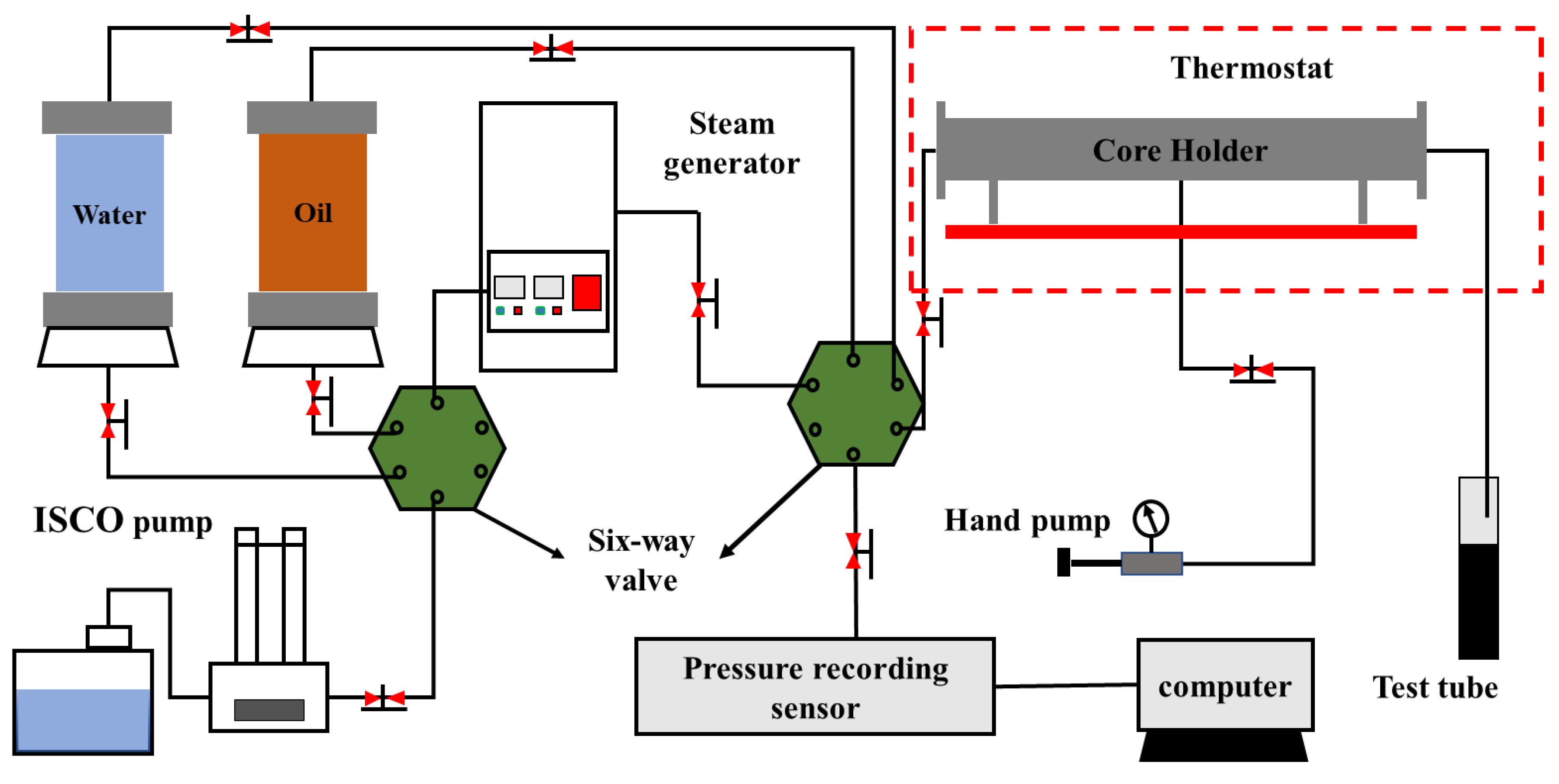
Figure 1. Schematic diagram of the steam flooding experiment system.
Energies 15 06246 g001
Figure 2. Production dynamic curve of steam flooding heavy oil at different temperatures. (a) Recovery, (b) water cut, (c) pressure, (d) ratio of recovery.
Energies 15 06246 g002
Figure 3. Recovery, water cut and pressure curves at different injection velocities. (a) Recovery, (b) water cut, (c) pressure, (d) ratio of recovery.
Energies 15 06246 g003
Figure 4. Recovery, water cut and pressure curves of heavy oil with different viscosities. (a) Recovery, (b) water cut, (c) pressure, (d) ratio of recovery.
Energies 15 06246 g004
Figure 5. Recovery, water cut and pressure curves of different permeability cores. (a) Recovery, (b) water cut, (c) pressure, (d) ratio of recovery.
Energies 15 06246 g005
Figure 6. Rheology curves of shear stress as function of shear velocity for produced oils at different temperatures and velocities of injection steam. (a) 140 °C, 1 mL/min; (b) 140 °C, 5 mL/min; (c) 200 °C, 1 mL/min; (d) 200 °C, 5 mL/min.
Energies 15 06246 g006
Table 1. Composition of the brine.
IonNa+, K+Ca2+Mg2+ClHCO3TDS
Concentration, mg·L−1363622089586068110,486
Table 2. Core physical properties and experimental schemes.
Oil SampleInjection Steam Temperature
°C
Porosity
%
Permeability
mD
Original Oil Saturation
%
Injection Velocity
mL/min
A12029.98395485.871
A14034.72406480.591
A20029.00389182.591
A14033.93401276.653
A14034.54392085.615
A20029.57408891.305
A12029.68784080.991
B20029.13386279.111
Table 3. SARA composition of the crude oil and oils produced at different temperatures and velocities of injection steam.
SampleSaturates, wt%Aromatics, wt%Resins, wt%Asphaltenes, wt%
Crude oil20.7425.5940.0614.39
140 °C
1 mL/min
fw = 016.2524.6940.3415.47
fw < 0.817.1726.540.6215.53
fw > 0.818.2224.4541.4515.61
140 °C
5 mL/min
fw = 019.6526.4639.1615.42
fw < 0.819.6325.139.4515.7
fw > 0.816.7226.540.3215.58
200 °C
1 mL/min
fw = 020.3529.834.0615.51
fw < 0.819.6726.0239.0115.92
fw > 0.815.2227.8740.0916.43
200 °C
5 mL/min
fw = 019.225.9337.3716.25
fw < 0.816.0928.4536.7117.47
fw > 0.815.0526.2639.8418.1
Publisher’s Note: MDPI stays neutral with regard to jurisdictional claims in published maps and institutional affiliations.