
The Heat-Storing Micro Gas Turbine—Process Analysis and Experimental Investigation of Effects on Combustion

 , , and
Abstract
:1. Introduction
1.1. Motivation and Concept
1.2. Literature Study
1.3. Scope of Work
2. Qualitative Analysis and Challenges of the Compound
2.1. Combustor
2.2. Turbomachinery and Heat Exchangers
2.3. Operation of the Compound
3. Methodology
3.1. Cycle Analysis
3.1.1. MGT

| Component | Value |
|---|---|
| ΔpRecu,air-side | 3.1% |
| ΔpCombustor | 3% |
| ΔpRecu,exhaust-side | 2.7% |
| ΔpWHX | 0.2% |
| ηRek | 89% |
| ηWHX | 95% |
| TIT | 1265 K |
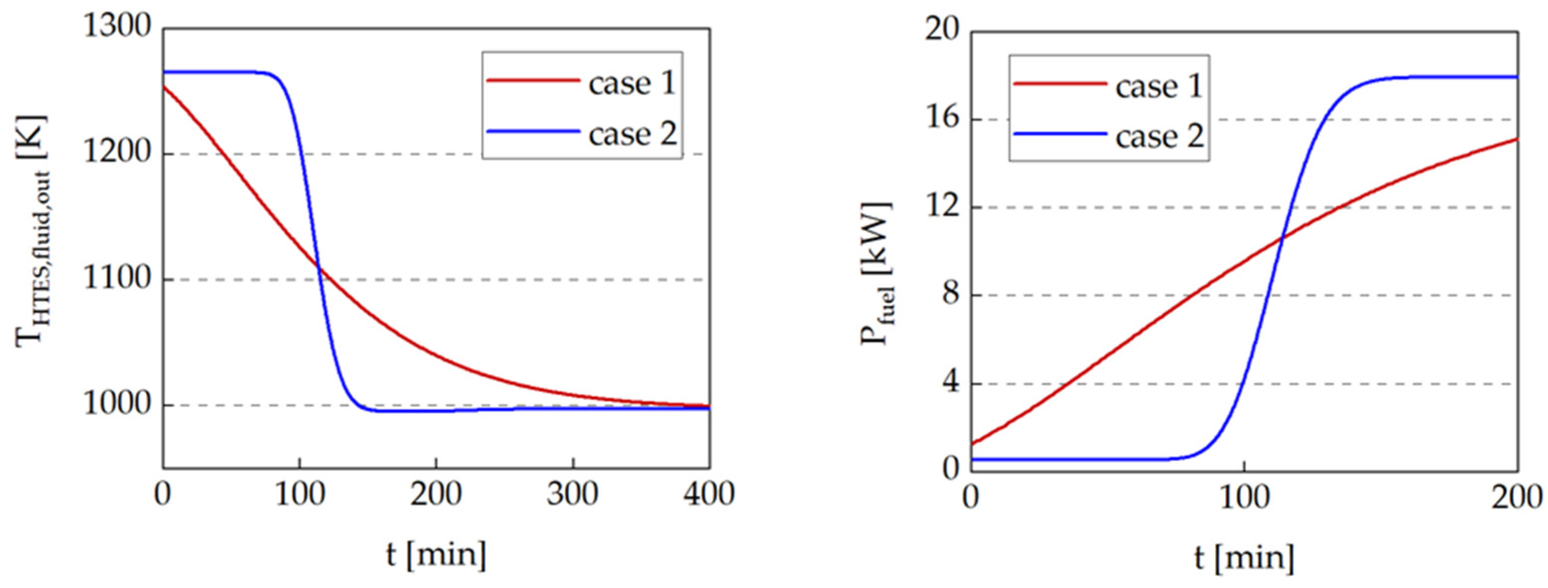
3.1.2. HTES
- Checker brick with low specific heat transport surface (av = 56 m2/m3) and low void fraction (ε = 30%)
- Honeycomb with very high specific heat transport surface (av = 1350 m2/m3) and high void fraction (ε = 68%)
| m | Q | H/D | V | av | ε | ΔpHTES | |
|---|---|---|---|---|---|---|---|
| Case 1: checker bricks | 363 kg | 40 kWh | 2 | 219 l | 30% | 56 m2/m3 | 4.2 Pa |
| Case 2: honeycomb bricks | 480 l | 68% | 1350 m2/m3 | 140 Pa |
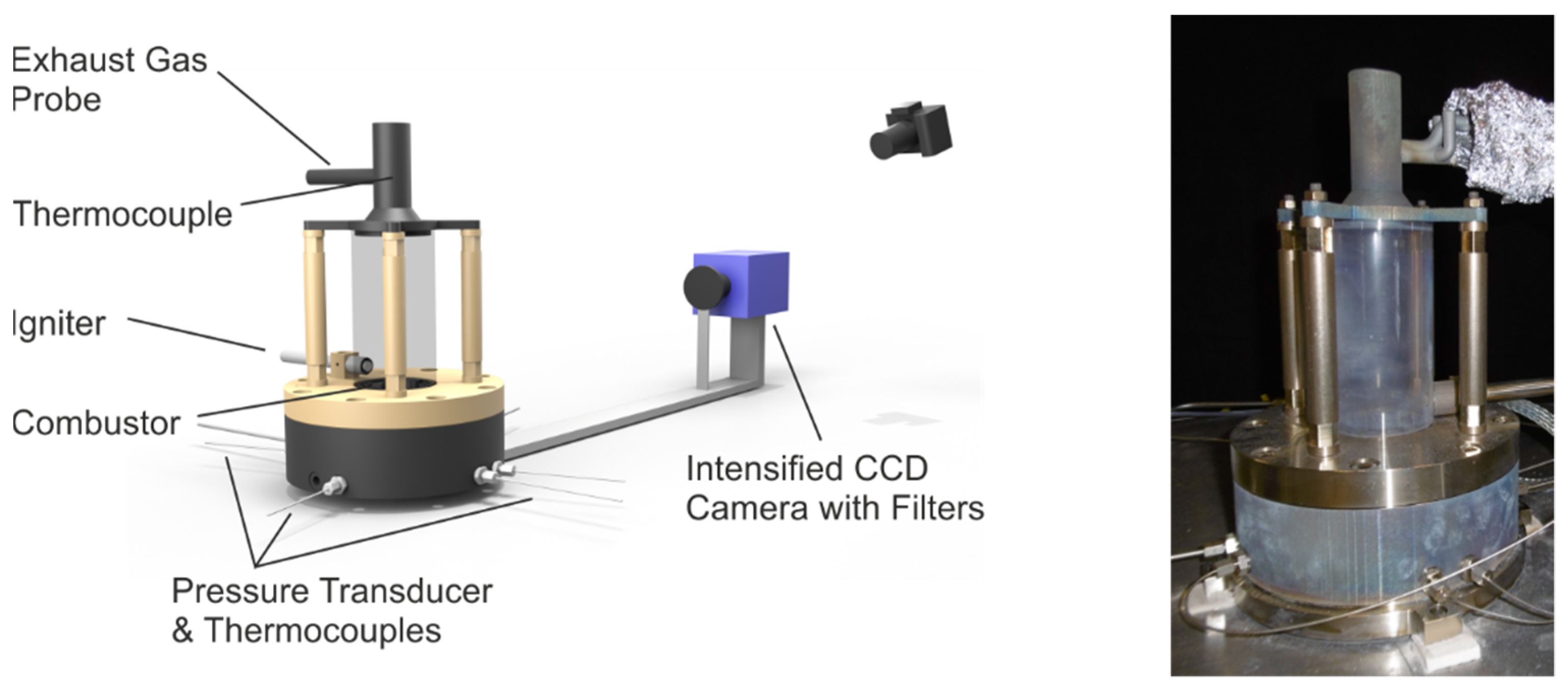
3.2. Combustor Development
4. Results
4.1. Numerical Results
General Combustor Requirements
- Fuel mass flow range: nominal fuel mass flow (0.38 × 10⁻³ kg/s) when the storage is empty and as low as possible while the HTES is being discharged
- Combustor inlet temperature: 973 K to 1265 K during operation and 293 K during start-up or when the HTES is cold
- Combustor inlet pressure: 1 × 10⁵–3 × 10⁵ Pa
4.2. Combustor Results
4.2.1. Parameter Range
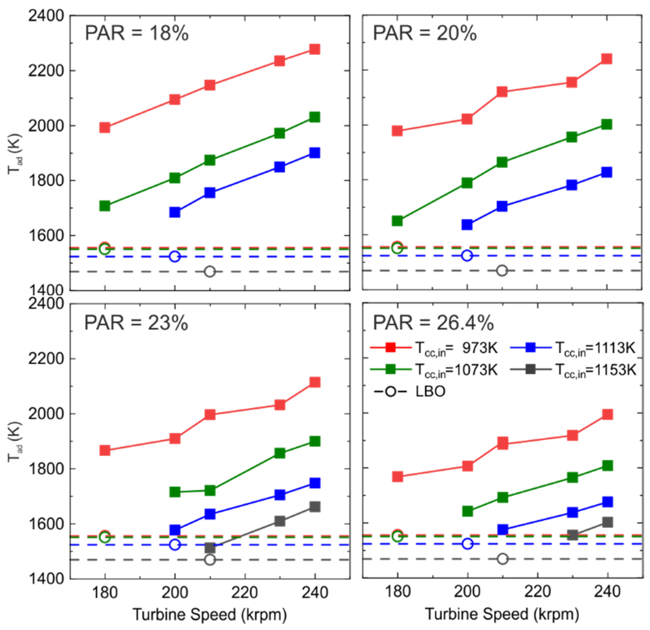
4.2.2. Stable Range of Operation-Numerical Investigations
4.2.3. Stable Range of Operation-Experimental Investigations
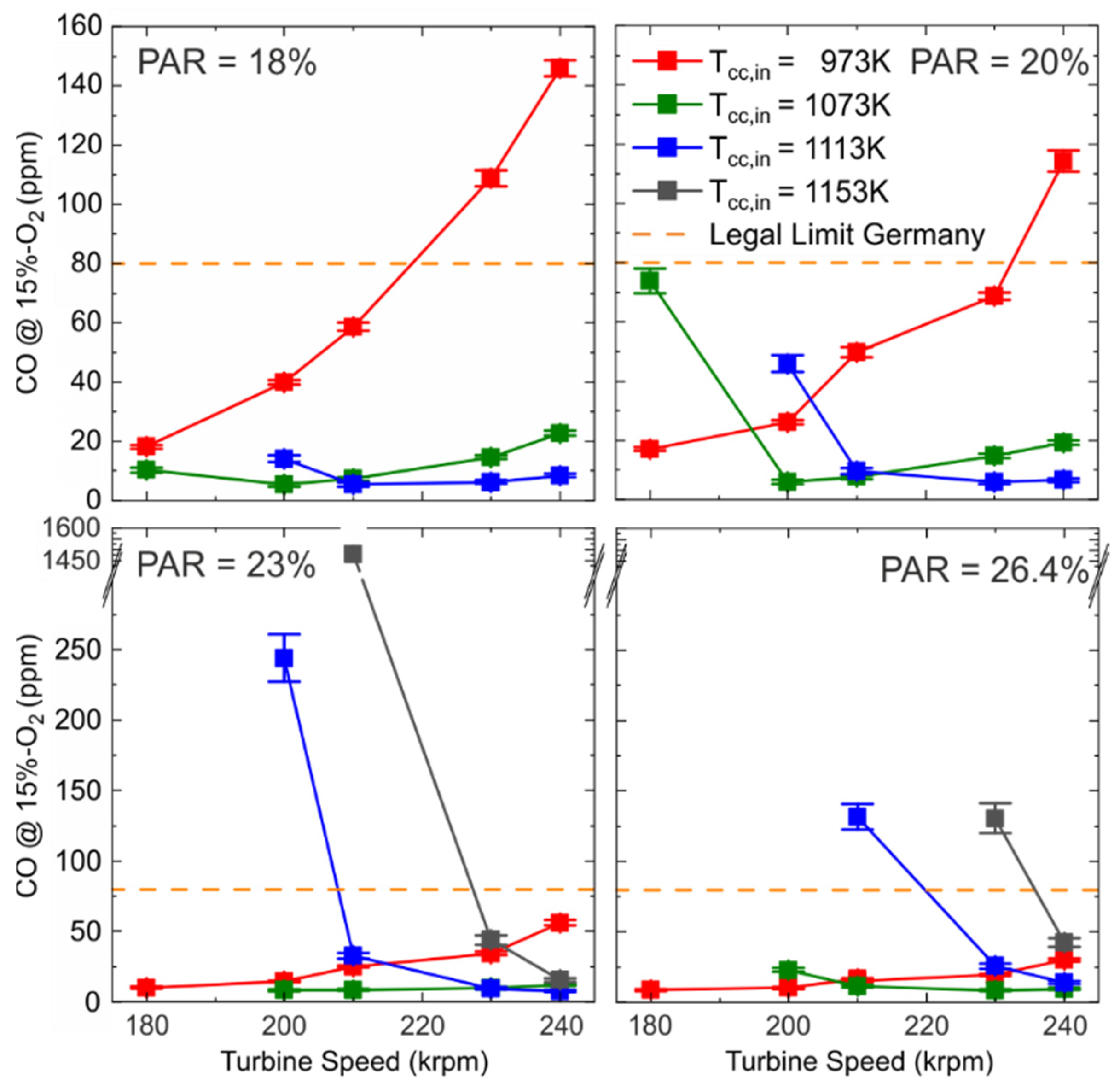
4.2.4. Emissions

5. Conclusions
Author Contributions
Funding
Acknowledgments
Conflicts of Interest
Nomenclature
| Greek | |
| ε | Porosity [%] |
| η | Efficiency [%] |
| Δ | Difference |
| λ | Air number [-] |
| Π | Pressure ratio [-] |
| Equivalence ratio [-] | |
| Ψ | Reduced heat loss [-] |
| Λ | Reduced length [-] |
| Alphanumeric Variables | |
| av | Specific surface [m2/m3] |
| m | Mass [kg] |
| Mass flow [kg/s] | |
| p | Pressure [Pa] |
| P | Power out [W] |
| Q | Heat capacity [Wh] |
| Heat flow [W] | |
| L/D | Length/Diameter ratio |
| PD | Reduced period duration |
| s | Entropy [J/K] |
| T | Temperature [K] |
| t | Time [min] |
| X | Volumetric fraction [mol/mol] |
| z* | Normalized space dimension [-] |
| Abbreviations | |
| ad | Adiabatic |
| ave | Average |
| comp | Compressor |
| el | Electrical |
| in | Inlet |
| isen | Isentropic |
| ov | Overall |
| rec | Recuperator |
| st | Stoichiometric |
| th | Thermal |
| turb | Turbine |
| AFR | Air fuel ratio |
| ATM | Atmospheric (Test Rig) |
| CC | Combustor |
| CCGT | Combined-cycle gas turbines |
| CHP | Combined heat and power |
| CO | Carbon monoxide |
| DLR | German Aerospace Centre |
| HTES | High temperature energy storage |
| MGT | Micro gas turbine |
| NOX | Nitrogen oxides |
| LBO | Lean blow-off |
| O2 | Oxygen (molecular) |
| PAR | Primary air ratio |
| TIT | Turbine inlet temperature |
| TOT | Turbine outlet temperature |
| WHX | Water heat exchanger |
References
- Bundesministerium für Umwelt, Naturschutz und Nukleare Sicherheit. Klimaschutzplan 2050 Klimaschutzpolitische Grundsätze und Ziele der Bundesregierung. Available online: https://www.bmu.de/fileadmin/Daten_BMU/Download_PDF/Klimaschutz/klimaschutzplan_2050_bf.pdf (accessed on 21 April 2020).
- Gemmer, B. Flexible Combined Heat and Power (CHP) Systems. Available online: https://www.energy.gov/sites/prod/files/2018/01/f47/Flexible%20CHP%20Comms_01.18.18_compliant.pdf (accessed on 14 April 2020).
- Thomas, B. Mini-Blockheizkraftwerke: Grundlagen, Gerätetechnik, Betriebsdaten, 2nd ed.; Vogel Buchverlag: Würzburg, Germany, 2011; ISBN 9783834332110. [Google Scholar]
- Pilavachi, P.A. Power Generation with Gas Turbine Systems and Combined Heat and Power. Appl. Therm. Eng. 2000, 20, 1421–1429. [Google Scholar] [CrossRef]
- Schaumann, G.; Schmitz, K.W. Kraft-Wärme-Kopplung; Springer: Berlin/Heidelberg, Germany, 2010; ISBN 978-3-642-01424-6. [Google Scholar]
- Pilavachi, P.A. Mini- and micro-gas turbines for combined heat and power. Appl. Therm. Eng. 2002, 22, 2003–2014. [Google Scholar] [CrossRef]
- Schmidt, F.W.; Willmott, A.J. Thermal Energy Storage and Regeneration; Hemisphere Publication Corp: Washington, DC, USA, 1981; ISBN 978-0070553460. [Google Scholar]
- Kuravi, S.; Trahan, J.; Goswami, D.Y.; Rahman, M.M.; Stefanakos, E.K. Thermal energy storage technologies and systems for concentrating solar power plants. Prog. Energy Combust. Sci. 2013, 39, 285–319. [Google Scholar] [CrossRef]
- Flueckiger, S.M.; Iverson, B.D.; Garimella, S.V.; Pacheco, J.E. System-level simulation of a solar power tower plant with thermocline thermal energy storage. Appl. Energy 2014, 113, 86–96. [Google Scholar] [CrossRef]
- Powell, K.M.; Edgar, T.F. Modeling and control of a solar thermal power plant with thermal energy storage. Chem. Eng. Sci. 2012, 71, 138–145. [Google Scholar] [CrossRef]
- Spelling, J.; Laumert, B.; Fransson, T. Advanced Hybrid Solar Tower Combined-cycle Power Plants. Energy Procedia 2014, 49, 1207–1217. [Google Scholar] [CrossRef]
- Stahl, K.; Moser, P.; Marquardt, R.; Siebert, M.; Kessler, S.; Maier, F.; Krüger, M.; Zunft, S.; Dreißigacker, V.; Hahn, J. Flexibilisierung von Gas- und Dampfturbinenkraftwerken durch den Einsatz von Hochtemperatur-Wärmespeichern (FleGs): F&E Vorhaben zur Vorbereitung von Hochtemperatur-Wärmespeichern und deren Integration in den Gas- und Dampfturbinenprozess; Abschlussbericht an BMWi/PTJ; Laufzeit: 01.12.2009–31.12.2012; Technische Informationsbibliothek u. Universitätsbibliothek: Hannover, Germany, 2013. [Google Scholar] [CrossRef]
- Li, D.; Hu, Y.; Li, D.; Wang, J. Combined-cycle gas turbine power plant integration with cascaded latent heat thermal storage for fast dynamic responses. Energy Convers. Manag. 2019, 183, 1–13. [Google Scholar] [CrossRef]
- Li, D.; Wang, J. Study of supercritical power plant integration with high temperature thermal energy storage for flexible operation. J. Energy Storage 2018, 20, 140–152. [Google Scholar] [CrossRef]
- Wojcik, J.; Wang, J. Technical Feasibility Study of Thermal Energy Storage Integration into the Conventional Power Plant Cycle. Energies 2017, 10, 205. [Google Scholar] [CrossRef] [Green Version]
- Gkoutzamanis, V.; Chatziangelidou, A.; Efstathiadis, T.; Kalfas, A.; Traverso, A.; Chiu, J. Thermal Energy Storage For Gas Turbine Power Augmentation. J. Glob. Power Propuls. Soc. 2019, 3, 592–608. [Google Scholar] [CrossRef]
- Bédécarrats, J.-P.; Strub, F. Gas turbine performance increase using an air cooler with a phase change energy storage. Appl. Therm. Eng. 2009, 29, 1166–1172. [Google Scholar] [CrossRef]
- Amelio, M.; Morrone, P. Numerical evaluation of the energetic performances of structured and random packed beds in regenerative thermal oxidizers. Appl. Therm. Eng. 2007, 27, 762–770. [Google Scholar] [CrossRef]
- Dreißigacker, V.; Belik, S. System Configurations and Operational Concepts for Highly Efficient Utilization of Power-to-Heat in A-CAES. Appl. Sci. 2019, 9, 1317. [Google Scholar] [CrossRef]
- Krüger, M.; Muslubas, S.; Loeper, T.; Klasing, F.; Knödler, P.; Mielke, C. Potentials of Thermal Energy Storage Integrated into Steam Power Plants. Energies 2020, 13, 2226. [Google Scholar] [CrossRef]
- Fricker, H.W. Regenerative thermal storage in atmospheric air system solar power plants. Energy 2004, 29, 871–881. [Google Scholar] [CrossRef]
- Pacheco, J.E.; Showalter, S.K.; Kolb, W.J. Development of a Molten-Salt Thermocline Thermal Storage System for Parabolic Trough Plants. J. Sol. Energy Eng. 2002, 124, 153–159. [Google Scholar] [CrossRef]
- Tamme, R.; Laing, D.; Steinmann, W.-D. Advanced Thermal Energy Storage Technology for Parabolic Trough. J. Sol. Energy Eng. 2004, 126, 794–800. [Google Scholar] [CrossRef]
- Steinmann, W.-D.; Tamme, R. Latent Heat Storage for Solar Steam Systems. In Proceedings of the 13th Solar-PACES International Symposium on Concentrated Solar Power and Chemical Energy Technology, Sevilla, Spain, 20–23 June 2006. [Google Scholar]
- Kölbig, M.; Bürger, I.; Linder, M. Thermal applications in vehicles using Hydralloy C5 in single and coupled metal hydride systems. Appl. Energy 2021, 287, 116534. [Google Scholar] [CrossRef]
- Linder, M.; Utz, I.; Schaube, F.; Molenda, M.; Wörner, A. Gas-Solid Reactions for Heat Applications. In Proceedings of the 5th International Hydrogen & Energy Symposium, Stoos, Switzerland, 23–28 January 2011; p. 21. [Google Scholar]
- Dreißigacker, V. Thermal Battery for Electric Vehicles: High-Temperature Heating System for Solid Media Based Thermal Energy Storages. Appl. Sci. 2021, 11, 10500. [Google Scholar] [CrossRef]
- Belik, S.; Dreißigacker, V. Electro-Thermal Analysis of Inductively Heated and Aerated Rod Bundle for Adiabatic Compressed Air Energy Storage. In Proceedings of the 12th International Renewable Energy Storage Conference, Düsseldorf, Germany, 13–15 March 2018. [Google Scholar]
- Wünning, J.A.; Wünning, J.G. Flameless Oxidation to Reduce Thermal NO-Formation. Prog. Energy Combust. Sci. 1997, 23, 81–94. [Google Scholar] [CrossRef]
- Cavaliere, A.; De Joannon, M. Mild Combustion. Prog. Energy Combust. Sci. 2004, 30, 329–366. [Google Scholar] [CrossRef]
- Zornek, T.; Monz, T.; Aigner, M. Experimentelle Charakterisierung eines Holzgas-Brenners für Mikrogasturbinen. In Proceedings of the VDI, 26th German Flame Day–Combustion and Furnaces, Duisburg, Deutschland, 11–12 September 2013; Volume 2161, pp. 775–778. [Google Scholar]
- Zornek, T.; Monz, T.; Aigner, M. A Micro Gas Turbine Combustor for the use of Product Gases from Biomass Gasification. In Proceedings of the 6th European Combustion Meeting, ECM 2013, Lund, Sweden, 25–28 June 2013; ISBN 978-91-637-2151-9. [Google Scholar]
- Zornek, T.; Monz, T.; Aigner, M. Effizient, flexibel, sauber-Flox-Brennkammersysteme für Mikrogasturbinen. BWK 2014, 66, 13–16. [Google Scholar]
- Bower, H.E.; Grimm, F.; Schwärzle, A.; Roth, J.; Zornek, T.; Kutne, P. Experimental Analysis of the Fuel Flexibility of a Jet-Stabilized Micro Gas Turbine Combustor Designed for Low Calorific Gases. In Proceedings of the GPPS Forum 2018, GPPS-2018, Zurich, Switzerland, 10–12 January 2018. [Google Scholar]
- Zanger, J.; Monz, T.; Aigner, M. Experimental Investigation of the Influence of Combustor Cooling on the Characteristics of a FLOX-Based Micro Gas Turbine Combustor. In Progress in Gas Turbine Performance; Benini, E., Ed.; InTech: London, UK, 2013; pp. 165–184. ISBN 978-953-51-1166-5. [Google Scholar]
- Zanger, J.; Monz, T.; Aigner, M. Experimental Investigation of the Combustion Characteristics of a Double-Staged FLOX-Based Combustor on an Atmospheric and a Micro Gas Turbine Test Rig. In Proceedings of the ASME Turbo Expo: Turbine Technical Conference and Exposition-2015, Montreal, QC, Canada, 15–19 June 2015; ASME: New York, NY, USA, 2015. ISBN 978-0-7918-5662-8. [Google Scholar]
- Seliger-Ost, H.; Kutne, P.; Zanger, J.; Aigner, M. Experimental Investigation of the Impact of Biogas on a 3 kW Micro Gas Turbine FLOX®-Based Combustor. J. Eng. Gas Turbines Power 2021, 143, 081020. [Google Scholar] [CrossRef]
- Lingstädt, T.; Grimm, F.; Krummrein, T.; Bücheler, S.; Aigner, M. Experimental Investigation Of An SOFC Off-Gas Combustor For Hybrid Power Plant Usage With Low Heating Values Realised by Natural Gas Addition. In Proceedings of the GPPS Forum 2018, GPPS-2018, Zurich, Switzerland, 10–12 January 2018. [Google Scholar]
- Seliger, H.; Huber, A.; Aigner, M. Experimental Investigation of a FLOX-Based Combustor For a Small-Scale Gas Turbine Based CHP System Under Atmospheric Conditions. In Proceedings of the ASME Turbo Expo: Turbine Technical Conference and Exposition-2015, Montreal, QC, Canada, 15–19 June 2015; ASME: New York, NY, USA, 2015. ISBN 978-0-7918-5662-8. [Google Scholar]
- Hasemann, S.; Seliger, H.; Kutne, P.; Aigner, M. Experimental and Numerical Design Study for a Small Scale Jet-Stabilized Micro Gas Turbine Combustor. In Proceedings of the ASME Turbo Expo: Turbomachinery Technical Conference and Exposition-2018, Oslo, Norway, 11–15 June 2018; American Society of Mechanical Engineers: New York, NY, USA, 2018. ISBN 978-0-7918-5098-5. [Google Scholar]
- Lingstädt, T.; Grimm, F.; Krummrein, T.; Kutne, P.; Aigner, M. Atmospheric Experimental Investigations of a Jet-Stabilized SOFC Off-Gas Combustor for a Hybrid Power Plant operated with Biogas. In Proceedings of the AIAA Scitech 2019 Forum, San Diego, CA, USA, 7–11 January 2019. [Google Scholar]
- Bücheler, S.; Huber, A.; Aigner, M. Development of a Jet-Stabilized Combustion System for the Use of Low-Caloric SOFC Off-Gas. In Proceedings of the ASME Turbo Expo: Turbine Technical Conference and Exposition-2017, Charlotte, NC, USA, 26–30 June 2017; The American Society of Mechanical Engineers: New York, NY, USA, 2017. ISBN 978-0-7918-5077-0. [Google Scholar]
- Panne, T.; Widenhorn, A.; Boyde, J.; Matha, D.; Abel, V.; Aigner, M. Thermodynamic Process Analyses of SOFC/GT Hybrid Cycles. AIAA J. 2007, 1, 25–27. [Google Scholar]
- Henke, M.; Monz, T.; Aigner, M. Inverted Brayton Cycle with exhaust gas recirculation-a numerical investigation. J. Eng. Gas Turbines Power 2013, 135, 091203. [Google Scholar] [CrossRef]
- Krummrein, T.; Henke, M.; Kutne, P. A highly flexible approach on the steady-state analysis of innovative micro gas turbine cycles. In Proceedings of the ASME Turbo Expo: Turbomachinery Technical Conference and Exposition-2018, Oslo, Norway, 11–15 June 2018; American Society of Mechanical Engineers: New York, NY, USA, 2018. ISBN 978-0-7918-5098-5. [Google Scholar]
- Agelidou, E.; Monz, T.; Huber, A.; Aigner, M. Experimental Investigation Of An Inverted Brayton Cycle Micro Gas Turbine For CHP Application. In Proceedings of the ASME Turbo Expo: Turbine Technical Conference and Exposition-2017, Charlotte, NC, USA, 26–30 June 2017; The American Society of Mechanical Engineers: New York, NY, USA, 2017. ISBN 978-0-7918-5077-0. [Google Scholar]
- Krummrein, T.; Henke, M.; Kutne, P.; Aigner, M. Numerical analysis of operating range and SOFC-off-gas combustor requirements of a biogas powered SOFC-MGT hybrid power plant. Appl. Energy 2018, 232, 598–606. [Google Scholar] [CrossRef]
- Goos, E.; Burcat, A.; Rustic, B. Extended Third Millennium Ideal Gas and Condensed Phase Thermochemical Database for Combustion with Updates from Active Thermochemical Tables. Available online: http://atct.anl.gov/ (accessed on 12 March 2020).
- Henke, M.; Monz, T.; Aigner, M. Validation of a t100 micro gas turbine steady-state simulation tool. In Proceedings of the ASME Turbo Expo: Turbine Technical Conference and Exposition-2015, Montreal, QC, Canada, 15–19 June 2015; ASME: New York, NY, USA, 2015. ISBN 978-0-7918-5662-8. [Google Scholar]
- Micro Turbine Technology, b.v. The Core of the EnerTwin. Available online: https://www.enertwin.com/enertwin-en/the-enertwin (accessed on 14 April 2020).
- Visser, W.; Oostveen, M. Development of a 3kW micro turbine for CHP applications. In Proceedings of the ASME Turbo Expo 2010, Glasgow, UK, 14–18 June 2010; ASME: New York, NY, USA, 2010. ISBN 978-0-7918-4396-3. [Google Scholar]
- Visser WP, J.; Shakariyants, S.A.; De Later MT, L.; Haj Ayed, A.; Kusterer, K. Performance Optimization of a 3kW Microturbine for CHP Applications. In Proceedings of the ASME Turbo Expo 2012, Presented at the 2012 ASME Turbo Expo, Copenhagen, Denmark, 11–15 June 2012; ASME: New York, NY, USA, 2012. ISBN 978-0-7918-4467-0. [Google Scholar]
- Ismail, K.; Stuginsky, R., Jr. A parametric study on possible fixed bed models for pcm and sensible heat storage. Appl. Therm. Eng. 1999, 19, 757–788. [Google Scholar] [CrossRef]
- Hausen, H. Wärmeübertragung im Gegenstrom, Gleichstrom und Kreuzstrom; Springer: Berlin/Heidelberg, Germany, 1950; ISBN 978-3-642-53135-4. [Google Scholar]
- Schmidt, I. Experimentelle Untersuchung Eines FLOX®-Basierten Brenners für Eine Mikrogasturbine mit Hohen Brennereintrittstemperaturen. Master’s Thesis, Universität Stuttgart, Stuttgart, Germany, 2021. [Google Scholar]
- Bundesministerium für Umwelt, Naturschutz und nukleare Sicherheit. Neufassung der Ersten Allgemeinen Verwaltungsvorschrift zum Bundes-Immisionsschutzgesetz (Technische Anleitung zur Reinhaltung der Luft–TA Luft). Available online: https://umweltmessung.com/wp-content/uploads/TA-Luft-2021-1.pdf (accessed on 25 January 2022).


| Parameter | Value |
|---|---|
| ΠComp | 3.1 |
| ηTurb,isen | 73.4% |
| Pel | 2.6 kW |
| Pth | 11.6 kW |
| Pfuel | 17.8 kW |
| ηel | 14.8% |
| ηov | 80% |
| Case 1 | Case 2 | |
|---|---|---|
| Δtdischarge [min] | 600 | 258 |
| Pel,ave [kW] | 2.62 | 2.59 |
| Pth,ave [kW] | 11.5 | 11.2 |
| Pfuel,ave [kW] | 14.5 | 10.4 |
| ηel,ave [%] | 18 | 24.8 |
| ηov,ave [%] | 97.3 | 132.6 |
| Δmfuel,saved [%] | 18 | 42 |
| Parameter | Values |
|---|---|
| Tcc,in [K] | 973/1073/1113/1153 |
| PAR [%] | 18/20/23/26.4 |
| N [krpm] | 180 … 240 |
| λ [-] | 1.6 … LBO |
| Air Number λ | High THTES,Fluid,out and/or Part Load | Low THTES,fluid,out and/or Base Load | Thermal Load on Inner Walls | |
|---|---|---|---|---|
| PAR increase | increase | risk of LBO | reduced risk of λ < 1 | decrease |
| PAR reduction | decrease | more stable | risk of λ < 1 | increase |
Publisher’s Note: MDPI stays neutral with regard to jurisdictional claims in published maps and institutional affiliations. |
© 2022 by the authors. Licensee MDPI, Basel, Switzerland. This article is an open access article distributed under the terms and conditions of the Creative Commons Attribution (CC BY) license (https://creativecommons.org/licenses/by/4.0/).
Share and Cite
Agelidou, E.; Seliger-Ost, H.; Henke, M.; Dreißigacker, V.; Krummrein, T.; Kutne, P. The Heat-Storing Micro Gas Turbine—Process Analysis and Experimental Investigation of Effects on Combustion. Energies 2022, 15, 6289. https://doi.org/10.3390/en15176289
Agelidou E, Seliger-Ost H, Henke M, Dreißigacker V, Krummrein T, Kutne P. The Heat-Storing Micro Gas Turbine—Process Analysis and Experimental Investigation of Effects on Combustion. Energies. 2022; 15(17):6289. https://doi.org/10.3390/en15176289
Chicago/Turabian StyleAgelidou, Eleni, Hannah Seliger-Ost, Martin Henke, Volker Dreißigacker, Thomas Krummrein, and Peter Kutne. 2022. "The Heat-Storing Micro Gas Turbine—Process Analysis and Experimental Investigation of Effects on Combustion" Energies 15, no. 17: 6289. https://doi.org/10.3390/en15176289
APA StyleAgelidou, E., Seliger-Ost, H., Henke, M., Dreißigacker, V., Krummrein, T., & Kutne, P. (2022). The Heat-Storing Micro Gas Turbine—Process Analysis and Experimental Investigation of Effects on Combustion. Energies, 15(17), 6289. https://doi.org/10.3390/en15176289