Article

Numerical Simulation on Borehole Instability Based on Disturbance State Concept

1
The Key Laboratory of Well Stability and Fluid & Rock Mechanics in Oil and Gas of Shaanxi Province, Xi’an Petroleum University, Xi’an 710065, China
2
School of Mechanical Engineering, Beijing Institute of Petrochemical Technology, Beijing 102617, China
3
School of Energy and Mining Engineering, Shandong University of Science and Technology, Qingdao 266510, China
*
Author to whom correspondence should be addressed.
Energies 2022, 15(17), 6295; https://doi.org/10.3390/en15176295
Submission received: 5 July 2022 / Revised: 20 August 2022 / Accepted: 23 August 2022 / Published: 29 August 2022

Abstract

:
This paper carries out a study on the numerical simulation of borehole instability based on the disturbance state concept. By introducing the disturbance damage factor into the classical Mohr–Coulomb yield criterio, we establish a finite element hydro-mechanical coupling model of borehole instability and program the relevant field variable by considering elastic–plastic deformation in borehole instability, the distribution of the damage disturbance area, the variation of porosity and permeability with the disturbance damage factor, etc. Numerical simulation shows that the borehole stability is related to the action time of drilling fluid on the wellbore, stress anisotropy, the internal friction angle of rock, and borehole pressure. A higher horizontal stress difference helps suppress shear instability, and a higher rock internal friction angle enhances shear failure around the borehole along the maximum horizontal principal stress. When considering the effect of the internal friction angle of rock, the rock permeability, disturbance damage factor, and equivalent plastic strain show fluctuation characteristics. Under the high internal friction angle of rock, a strong equivalent plastic strain area and disturbance damage area occur in the direction of the maximum horizontal principal stress. Their cloud picture shows the mantis shape, where the bifurcation corresponds to the whiskers of the shear failure area in borehole instability. This study provides a theoretical basis for solving the problem of borehole instability during drilling engineering.

1. Introduction

In the oil and gas industry, 50–80% of exploration and development costs are spent on drilling. The downhole accidents such as wellbore shrinkage, sticking, formation collapse, and leakage caused by borehole instability lead to an increase in the drilling cycle, the damage of downhole equipment, and an increase in the cost, which has restricted oil and gas exploration and development [1,2,3]. The core of high-quality, safe, efficient, and low-cost drilling is to evaluate the downhole surrounding rock environment, study the mechanism of borehole instability, and control the borehole instability, and it is of great theoretical and practical significance [4,5,6].
The disturbance state concept (DSC) was proposed by Desai in 1974 in the United States [7], and a relatively complete theoretical system was formed. The DSC has been applied in metal, welding material, soil, rock, oil sand, concrete, and electronic packaging materials. Research on the DSC started from the material mechanical response, hierarchical single surface model, and numerical simulation method. In 1992, Desai et al. established a DSC-based unified constitutive model for study on the static behavior of rock joints and interfaces [8]. In 1995, Katti et al. established a DSC-based clay constitutive model for the prediction of the response of stress–strain and pore pressure of undrained saturated clay under cyclic loading, as well as the response of soil under earthquake [9]. Desai et al. introduced the viscoplastic constitutive relation into the DSC to describe the response of the material in the relatively intact state [10]. In 1996, Desai et al. established a constitutive model based on stress–strain and non-destructive behavior and used DSC to describe the crack density [11]. In 1998, Desai et al. used the DSC-based numerical simulation method to establish the governing equation, disturbance function, and finite element equation of the relatively complete state and fully adjusted state [12]. In 1996, Pal integrated DSC and computer methods to describe the mechanical behavior of the solid and contact face [13]. In 2016, Fan et al. established a general compression model of metal-rich clay based on the general DSC compression model [14]. In 2017, Ouria et al. used the DSC function to describe the coefficient of compressibility of structural soil [15]. In 2018, Ghazavi Baghini et al. applied DSC to simulate the behavior of the pile under the axial load [16].
In China, some research progress has been made on DSC since 2000. Wu et al. applied the DSC to establish the nonlinear constitutive model and elastic–plastic constitutive model of rock [17]. Zheng et al. developed the method of describing the triaxial compression response of rock and the stress anisotropic response of soil based on DSC [18] and proposed a evolution equation of the disturbance factor through a mesoscopic analysis of the DSC established by the hardening model [19]. Zhang et al. established a creepage model of structural soft soil based on DSC [20]. Fu et al. proposed two methods of disturbance factor evolution based on the conventional triaxial test curve and the volumetric strain threshold, and the limit state of deviator strain energys [21]. Yang et al. applied the DSC hardening parameters to establish a structural clay boundary surface model [22]. Huang et al. established a creepage disturbance factor model with time as an independent variable [23]. Zou et al. established a stress–strain model of hydrated soil with the DSC method to describe the process of the failure of the cement structure [24]. The application of the DCS method in borehole stability is still not reported [25,26,27].
In previous mechanical theory, it was supposed that the cracks and damage inside the borehole rock have no strength [27,28,29,30,31,32,33,34,35,36,37,38,39,40]. In the DCS, it is proposed that the cracks and damaged parts are caused by the continuous merging and integration of defects in the internal complex microstructure, and they still have a certain strength and reflect softening and weakening caused by the propagation of crack and failure and hardening and strengthening caused by continuous compression. The DCS reveals the mechanism of the mechanical response of the borehole wall. Moreover, the DCS suggests that various forces cause the disturbance of the material microstructure, and the self-adjustment of the material internal microstructure includes relative motion that leads to damage, softening, or compression hardening of the material and macroscopically obvious disturbance. A description of disturbance through macroscopic observation provides the method of a cross-scale analysis of the micro-response of internal complex microstructure and the macroscopic behavior of yield failure in borehole rock. In the DCS, the material is considered as a random mixture under the relatively intact stage and the fully adjusted state, which correspond to the undamaged part and the damaged part in previous models. Material deformation and failure caused by disturbance is a process of transition from a relatively intact state to a fully adjusted state through self-adjustment and self-organization.
To overcome the defects and limits of conventional methods such as fracture mechanics, damage mechanics, and configuration mechanics, we carried out a numerical simulation of borehole instability based on the DSC by considering microscopic to macroscopic effects and the multi-regional response of borehole rock. We revealed the mechanism and evolution of borehole instability and developed a system for DSC-based study on borehole stability.
The paper is organized as follows. Section 2 introduces the mechanical theories and methods of borehole stability, including the mechanical equilibrium equation, seepage equation, the theory of borehole instability in a disturbed state, and model verification. Section 3 introduces the finite element model for borehole instability, mesh division, boundary conditions, and secondary development of subroutine. Section 4 discusses the numerical simulation results and analyzes the effects of action time of drilling fluid on the wellbore; stress anisotropy; internal friction angle; and borehole pressure on the equivalent plastic strain, permeability, borehole wall stress, and disturbance damage factor. The main conclusions of this study are summarized in the last section.

2. Theory and Method

2.1. Mechanical Equilibrium Equation

According to rock mechanics, the mechanical equilibrium equation of rock borehole stability is expressed as [41,42,43]:
σ i j , j + X i = 0
where σij is the stress tensor component; Xi is the body force vector component.
Assuming small rock deformation, the geometric equation of borehole stability is expressed as:
ε i j = 1 2 ( u i , j + u j , i )
where εij is the strain tensor component; ui is the displacement vector component.
According to the effective stress of porous media, we have [44]:
σ i j = σ i j α p δ i j = C i j k l : ε k l
where Cijkl is the stiffness tensor component; p is the pore pressure; α is the Biot constant; σ i j is the effective stress tensor component; δij is the Kronecker symbol, which is 0 when i = j and 0 when ij.

2.2. Seepage Equations

According to the theory of seepage mechanics, the fluid seepage equation in the borehole surrounding rock is expressed as [45]:
( k μ p ) = 1 M p t α ε v t
where k is the permeability tensor; εV is the volumetric strain component; M is the Biot modulus; and t is the time of the drilling fluid action on the borehole wall.

2.3. Theory of DSC Borehole Instability

The basic principle of the DSC is to consider the material under stress disturbance as a random mixture in an undisturbed state and a completely disturbed state, and its mechanical response is determined by a weighted average of the mechanical response of the part in an undisturbed state and the part in a completely disturbed state. The undisturbed state refers to that the material is at the idealized state or the undisturbed and little disturbance state which is defined subjectively. For example, a stable material with a hardening response is in an undisturbed state. The completely disturbed state refers to the limit of the material under stress disturbance. According to the DSC principle, the basic elements include the undisturbed state, the completely disturbed state, and the disturbance function.
The establishment of the model requires a definition of the basic elements, where the undisturbed state corresponds to the non-crack (non-damaged) part in the damage mechanics constitutive model, and the completely disturbed state corresponds to the damaged part; the disturbance function corresponds to the damage function. The crack (damage) part has no strength; the completely disturbed state part has specific stress–strain and strength; and the disturbance function characterizes softening (damage), strengthening, and hardening.
Damage to the rock affects the effective shear strength parameters c and ϕ , which are the function of the disturbance state. Under the action of disturbance and pore pressure, the Mohr–Coulomb criterion of rock failure is expressed by effective stress, pore pressure, and effective shear strength as follows:
τ n 1 D = c + σ n + D p w 1 D tan ϕ
where D is the disturbance damage factor; τn is the shear stress; and pw is the pore pressure.
Assuming that the rock’s uniaxial compressive strength is σc and the uniaxial compressive strength of the damaged rock is σ c = ( 1 D ) σ c , the relationship between the shear strength and uniaxial compressive strength is expressed as
σ c = ( 1 D ) σ c = ( 1 D ) 2 c cos ϕ 1 sin ϕ
By solving the above two equations, the effective shear strength parameters c and ϕ are expressed as a function of stress σn and τn on the failure surface, the compressive strength σc of non-damaged rock, and disturbance damage factor D.
When the equivalent plastic strain of a rock element exceeds the limit plastic strain ε ¯ p max , plastic deformation and failure occur. The relationship between the disturbance damage factor and the equivalent plastic strain satisfies the first-order exponential decay function, and the equivalent plastic strain is normalized as:
D = A 0 e ε ¯ p n / a + B 0
where ε ¯ p n is the normalized equivalent plastic strain and the material parameter a is a constant, which is equal to 0.2 in the simulation. A 0 = 1 e 1 / a 1 and B 0 = 1 e 1 / a 1 . The parameter a reflects the rate of the disturbance damage factor evolution with the plastic strain.
In the hydro-mechanical coupling system, the solid phase is expressed as S = Un + Da, where Un is the undamaged phase, Da is the damaged solid phase, and L is the liquid phase. The Da component cannot support the shear load, and the Un component can support the shear stress and hydrostatic pressure. Therefore, the load capacity of the rock is reduced, i.e., damage has occurred. Assuming that the volume of the porous medium is V, the damaged volume is expressed as:
V D = V ( 1 n ) D
where n is the rock porosity and D is the disturbance damage factor.
According to the cubic law of seepage [44], the rock permeability coefficient is evolved as follows:
k = ( 1 D ) k M + D k D ( 1 + ε v p F ) 3
where kM and kD are the permeability coefficients of non-damaged and fractured rock, respectively, and ε v p F is the plastic volumetric strain of the damage phase.
Assuming that no damage occurs during the elastic deformation of the rock, and plastic deformation and damage occur simultaneously, ε v p F is expressed as:
ε v p F = D ε v p
where ε v p is the plastic volume strain.

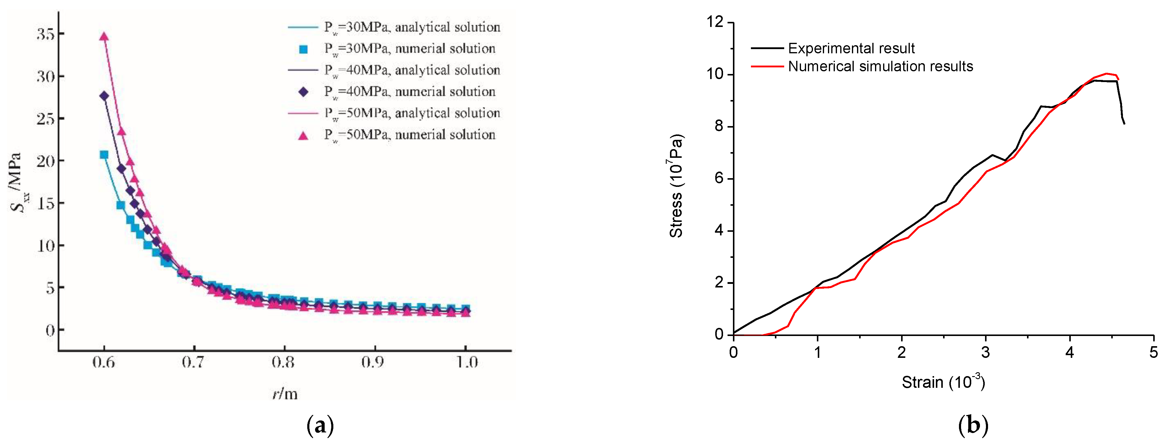
2.4. Model Validation

According to rock mechanics, there is an analytical solution for the stress field around the borehole in the homogeneous formation. The analytical solution and finite element solution of the stress field component Sxx are calculated by setting the bottom hole pressure as 30 MPa, 40 MPa, and 50 MPa [41,45] (Table 1 and Figure 1a), and the solutions have a good agreement, which verifies the reliability of the finite element solution under the hydro-mechanical coupling conditions.
To validate our DCS theory, we compare the numerical results with experimental results, as shown in Figure 1b. The cohesive force is 30.7 MPa and the friction angle is 27°. The bulk and shear modulus of rock sample are 22 GPa and 16 GPa, respectively. The initial fracture toughness is equal to 12 MPa·mm0.5. We observe that the numerical results have a good agreement with the experimental results, which indicate that our DSC model are reliable.

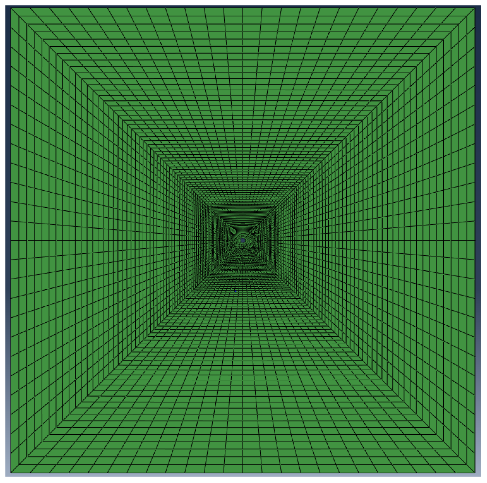
3. Finite Element Model

A 2D 20 m × 20 m finite element model is established, and a borehole with a radius of 0.1m is drilled in the middle of the model (Figure 2). The model is meshed with the structured grid of the plane strain quadrilateral elements (CPE4P) coupled with the degree of freedom of the pore pressure. To simulate the stress concentration around the borehole, the meshes near the borehole are refined locally. The mesh size of the directional quadrilateral elements away from the borehole increases gradually. The finite element model of borehole stability includes a total of 9024 nodes and 8928 CPE4P quadrilateral elements. The basic input parameters are listed in Table 2.
This finite element simulation of borehole stability is completed in two steps. The first is to establish the stress balance equation, which provides the initial stress field for the DSC-based numerical simulation of borehole instability. The second is to carry out a finite element simulation of borehole instability, and it is operated in a Soils hydro-mechanical coupling solver in ABAQUS. The solver numerically discretizes the time derivative term through an implicit algorithm. The time step is adaptive. The initial time step is 0.1 s. The minimum and maximum are 1 × 10⁻⁹ s and 86,400 s. The elastic–plastic deformation of the borehole wall rock is simulated by the Mohr–Coulomb plastic yield criterion. The rock internal friction angle and the dilation angle of rock are listed in Table 1.
As shown in Figure 1, the boundary conditions of this finite element model are set as follows: the normal displacement constraint of the outer boundary is 0, that is, the roller boundary condition is satisfied, and pore pressure is applied to the outer boundary and the inner boundary of the borehole. It is noted that the PORMECH keyword in the ABAQUS input file converts pore pressure into surface force and applies it to the borehole wall to simulate the force of the mud column pressure on the borehole wall.
Based on Section 2.3 of this paper, “Theory of Borehole Instability in Disturbed State”, the secondary development is carried out on the commercial finite element software ABAQUS platform, and the USDFLD subroutine is used to realize the porosity, permeability coefficient, disturbance damage factor, and equivalent plastic stress (PEEQ). In this program, the relationships of the permeability coefficient and equivalent plastic stress with the disturbance damage factor are coded by using Equations (8) and (9). The evolution of other parameters is used to obtain the instability process of rock borehole.

4. Results and Analysis

The effects of the action time of drilling fluid on the wellbore, stress anisotropy, internal friction angle of rock, and borehole pressure on borehole stability are simulated with the parameters listed in Table 1. In the cloud picture of equivalent plastic deformation and disturbance damage factor, the horizontal direction is set as the x axis, and the vertical direction is set as the y axis.

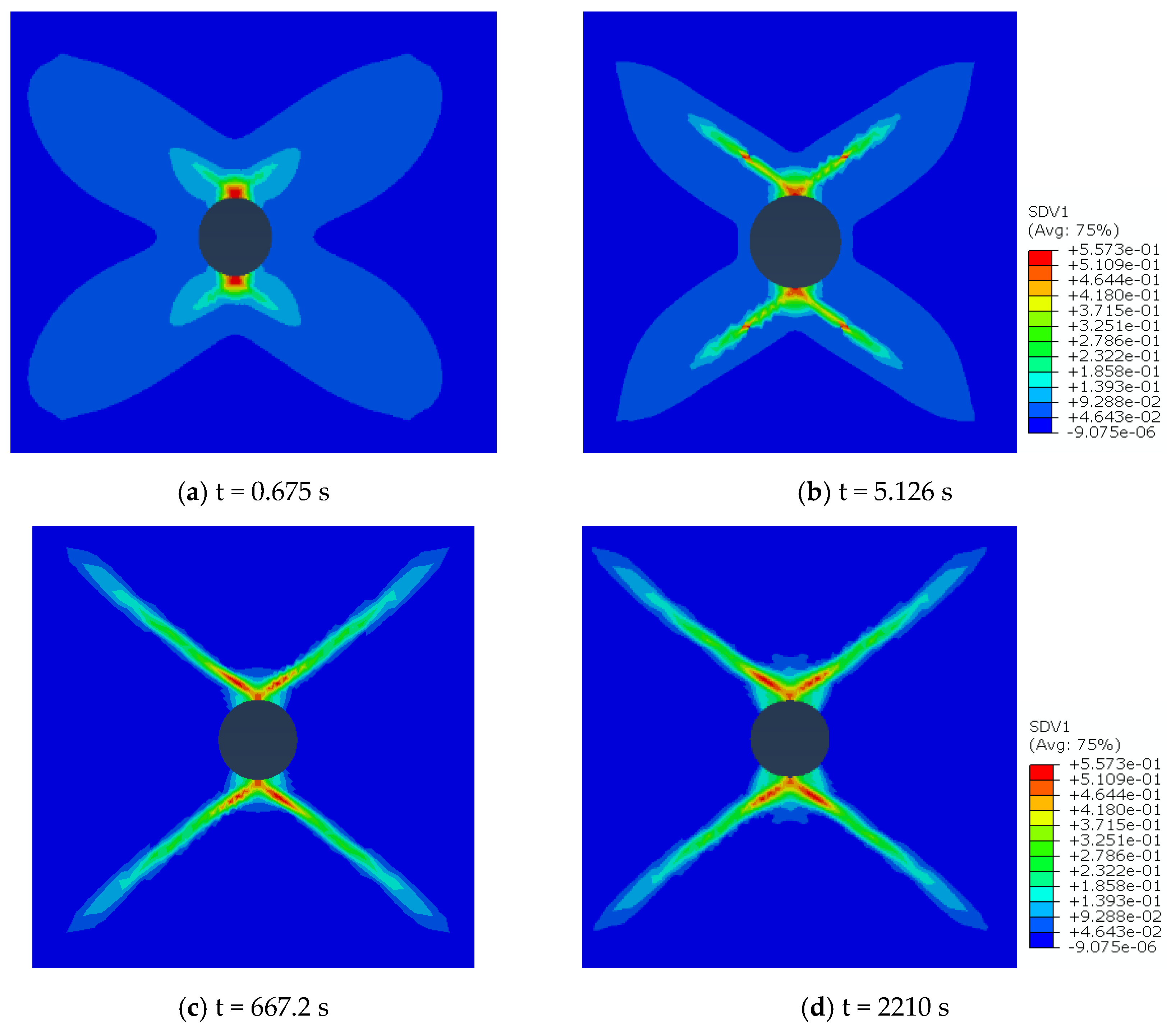
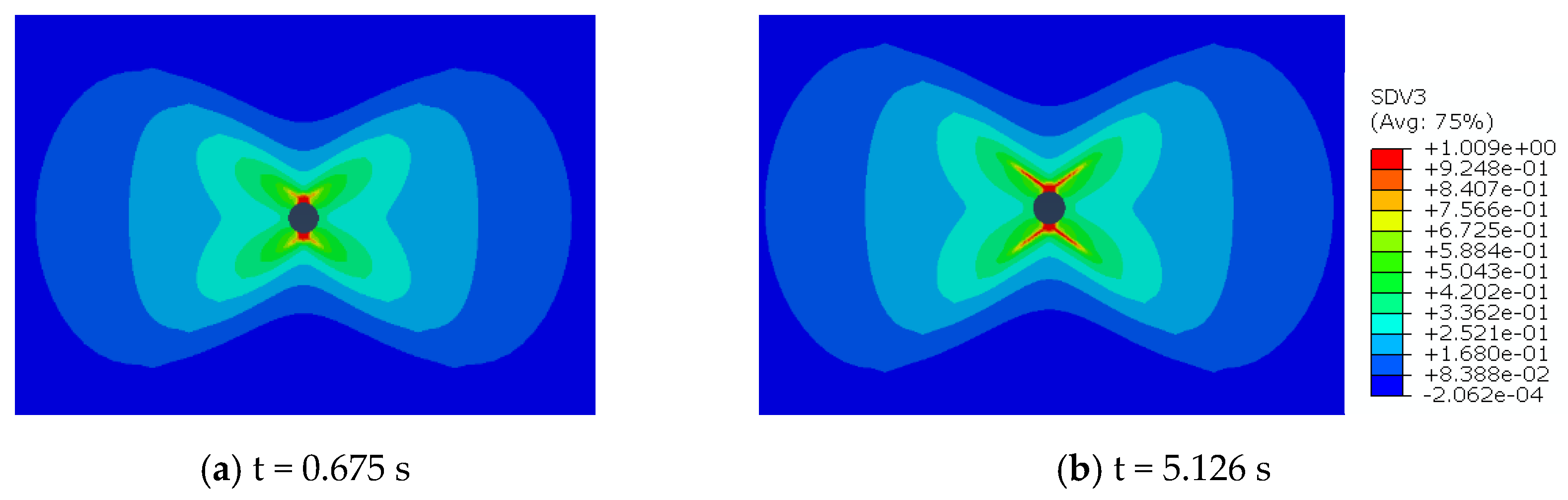
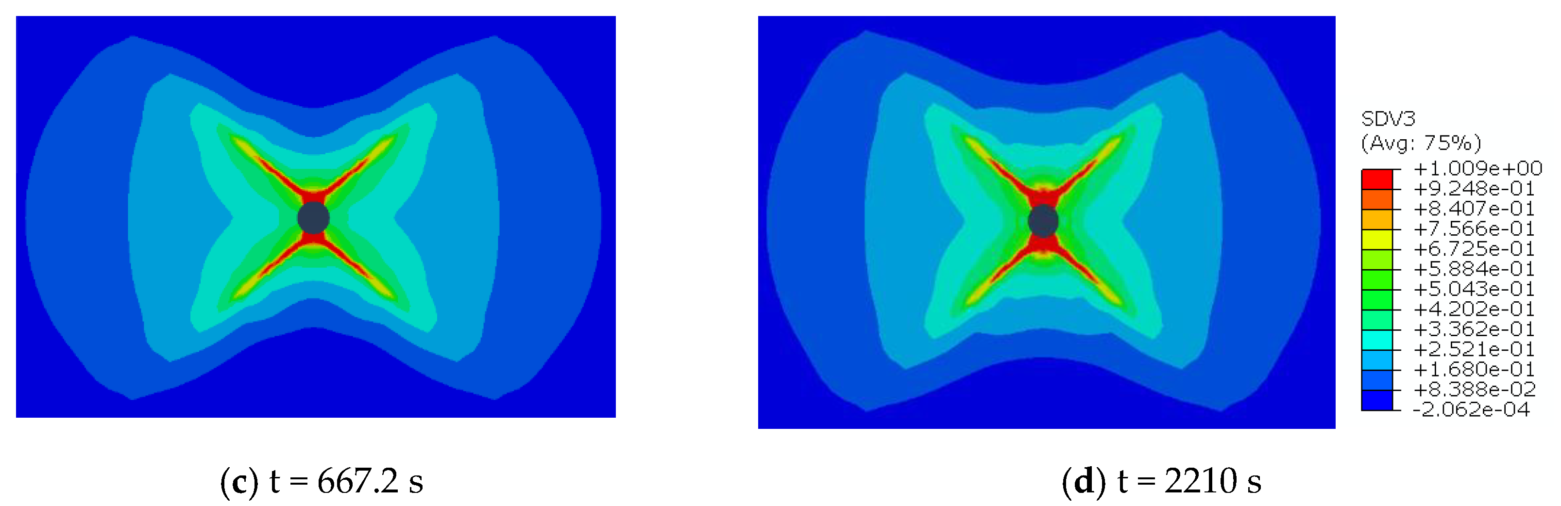
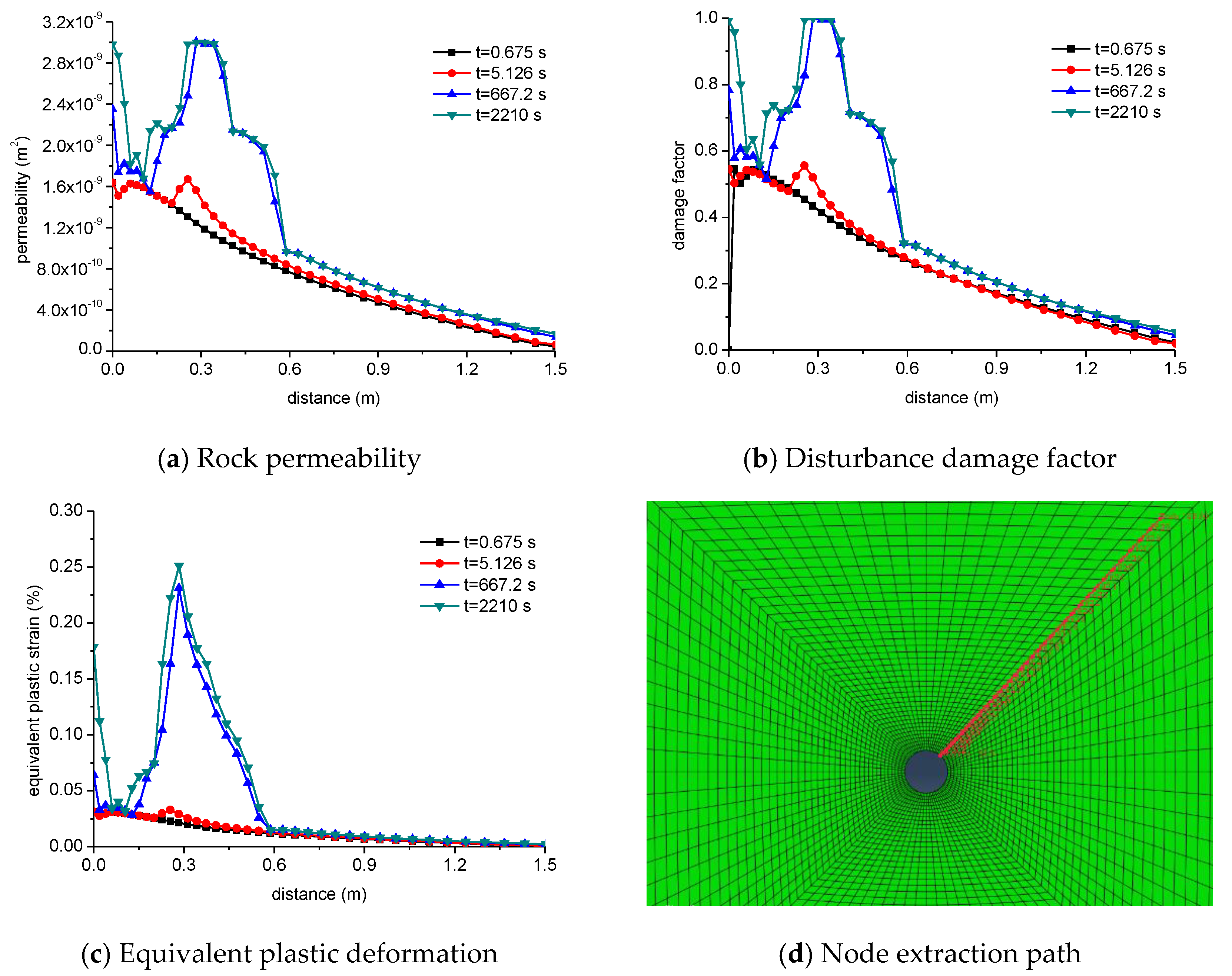
4.1. Effect of Action Time of Drilling Fluid on the Wellbore

During drilling, the borehole is filled with the drilling fluid, and the action time of the drilling fluid on the wellbore affects the borehole instability. Here, the effects of the action time of the drilling fluid on the wellbore (i.e., t = 0.675 s, t = 5.126 s, t = 667.2 s, and t = 2210 s) are simulated.
The cloud picture of equivalent plastic strain under different action times of drilling fluid on the wellbore is shown in Figure 3. At the initial stage of the action time of the drilling fluid, the equivalent plastic strain is concentrated around the borehole in the maximum principal stress direction. As the drilling operation continues, the equivalent plastic strain region gradually expands to the periphery of the borehole, showing a typical symmetrical bifurcated feature, which is due to rock shear damage.
The cloud picture of the disturbance damage factor of borehole instability under different action times of drilling fluid on the wellbore is shown in Figure 4. Initially, the rock damage region is concentrated around the borehole in the maximum principal stress direction. Then, the rock damage region develops as the equivalent plastic strain region. The disturbance damage factor gradually expands to the periphery of the borehole and shows symmetrical bifurcation characteristics, indicating the dominant mechanical mechanism of borehole instability as a shear failure.
The rock permeability, disturbance damage factor, and equivalent plastic strain with different distances from the borehole are shown in Figure 5. The node extraction path is shown in Figure 5d. As the distance from the borehole increases, the rock permeability, disturbance damage factor, and equivalent plastic strain value gradually decrease. As the action time of drilling fluid on the wellbore increases, the rock permeability, disturbance damage factor, and plastic strain area increase slightly. At a distance of 0.3 m from the borehole, the permeability, disturbance damage factor, and plastic strain change abruptly, indicating serious damage.

4.2. Effect of Stress Anisotropy

The rock yield failure is related to its stress state, and the in situ stress affects borehole stability during drilling. The effects of the horizontal stress difference of 0 MPa, 5 MPa, 7.5 MPa, and 10 MPa are simulated.
The cloud picture of equivalent plastic strain around the borehole under various horizontal stress differences is shown in Figure 6. Under the isotropic stress (the stress difference of 0 MPa), the equivalent plastic strain area occurs around the borehole and shows the symmetrical distribution on the x axis and y axis. As the stress anisotropy is enhanced, the equivalent plastic strain region grows in a narrow region in the x direction and grows longer in the y direction. The shape of the equivalent plastic strain cloud picture in Figure 6b,c is similar to the cockroach, and the bifurcation is similar to the whiskers. Under the low stress anisotropy, there are multiple bifurcations on the equivalent plastic strain region, indicating several shear failures. Under the stress anisotropy of 10 MPa, only one bifurcation occurs in the y direction, shear failure is significantly reduced, and the plastic strain zone occurs along the 45° direction. As the stress anisotropy increases, the shear failure area is reduced.
The cloud picture of damage factor distribution around the borehole under different stress anisotropy is shown in Figure 7. As the stress anisotropy is enhanced, the rock damaged area in the x axis is narrowed and elongated in the y axis. As the stress anisotropy reduces, the bifurcation increases. Under the strong stress anisotropy of the stress difference of 10 MPa, only one bifurcation occurs in the y axis, and the shear damage zone is generated along the 45° direction.
The rock permeability, disturbance damage factor, and equivalent plastic strain with the distance from the borehole during the borehole instability along the direction of the nodal path are shown in Figure 8. As the distance from the borehole increases, the rock permeability, disturbance damage factor, and plastic strain generally show a decreasing trend. Under the low stress anisotropy, the permeability, disturbance damage factor, and plastic strain show fluctuation characteristics, corresponding to multiple bifurcations in Figure 7. As the shear damage increases, the damage region increases. Under the higher stress anisotropy, the rock permeability, disturbance damage factor, and equivalent plastic strain fluctuate at a relatively low level, which is consistent with the condition of one bifurcation in the y direction in Figure 7d.

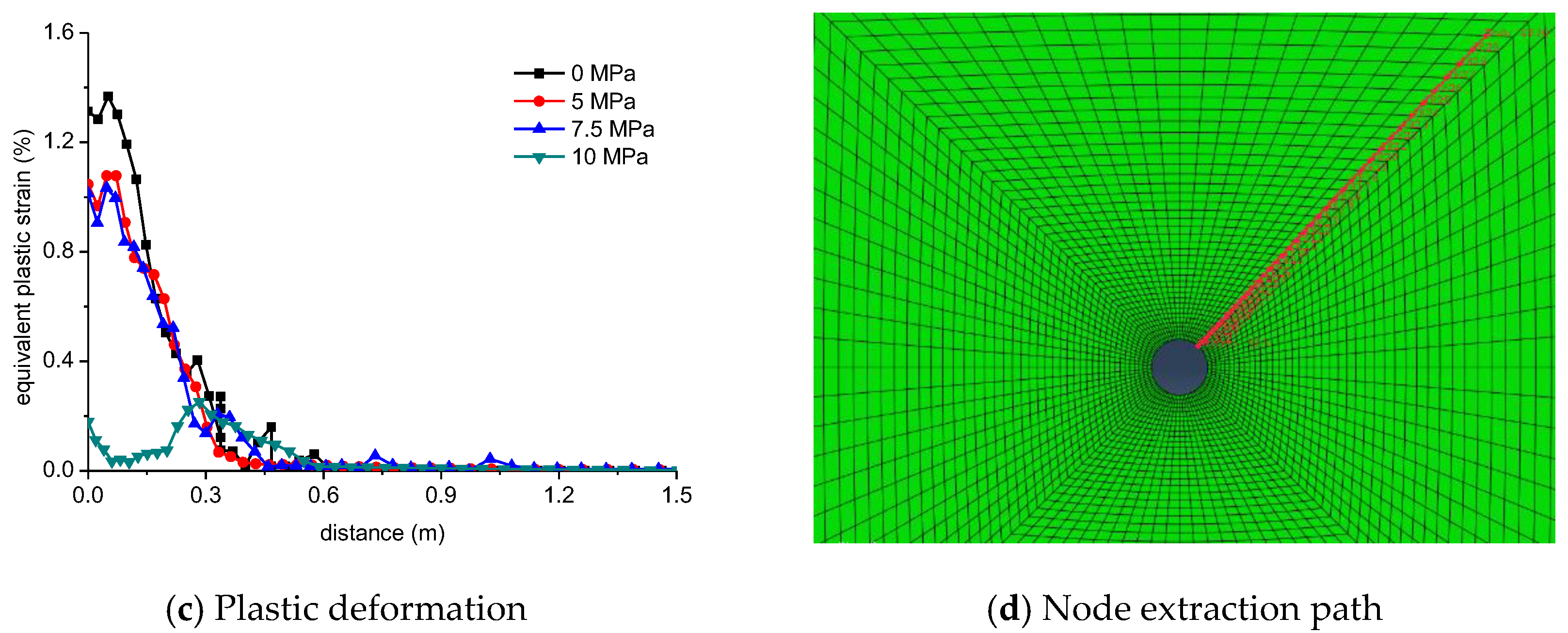
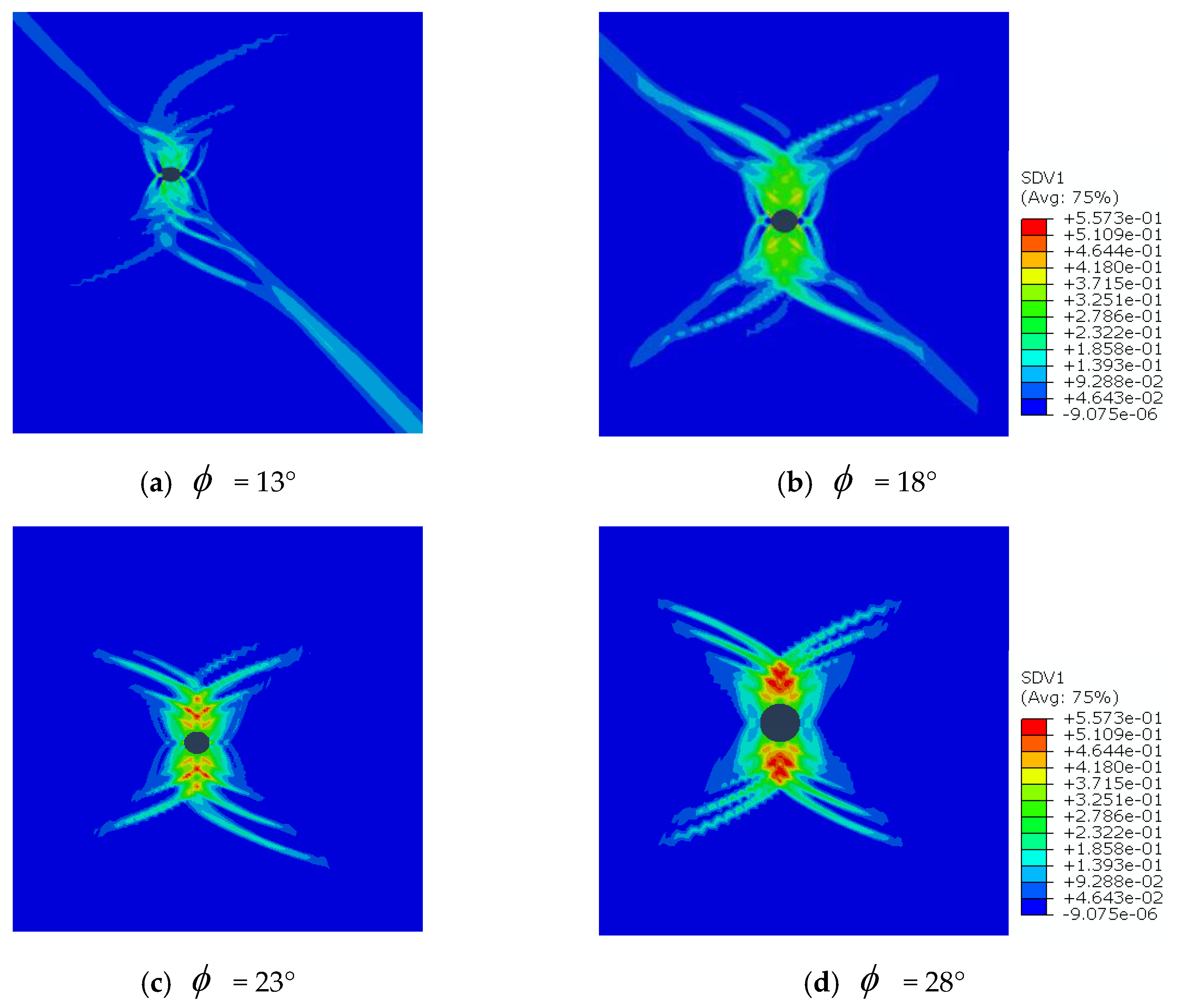
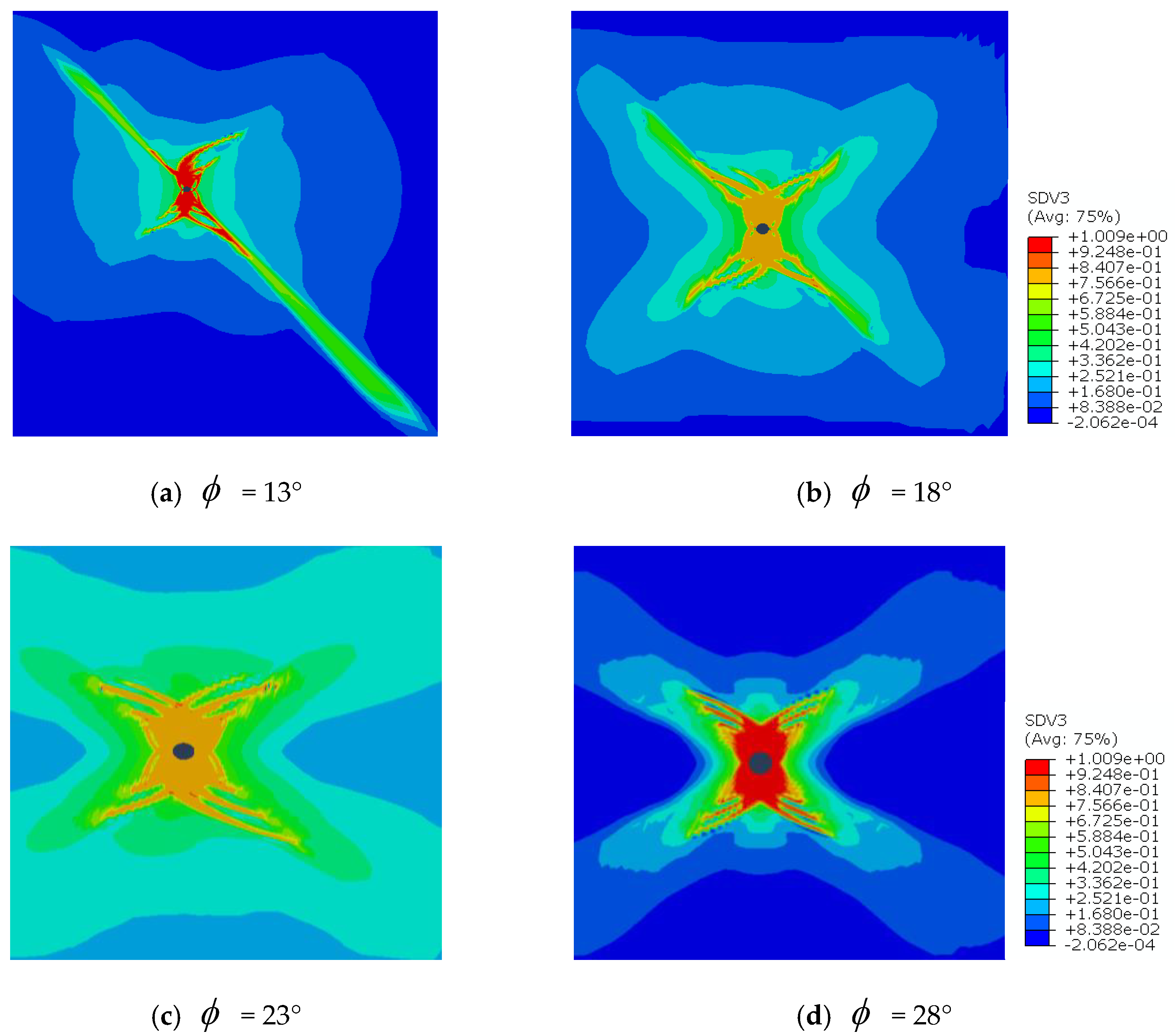
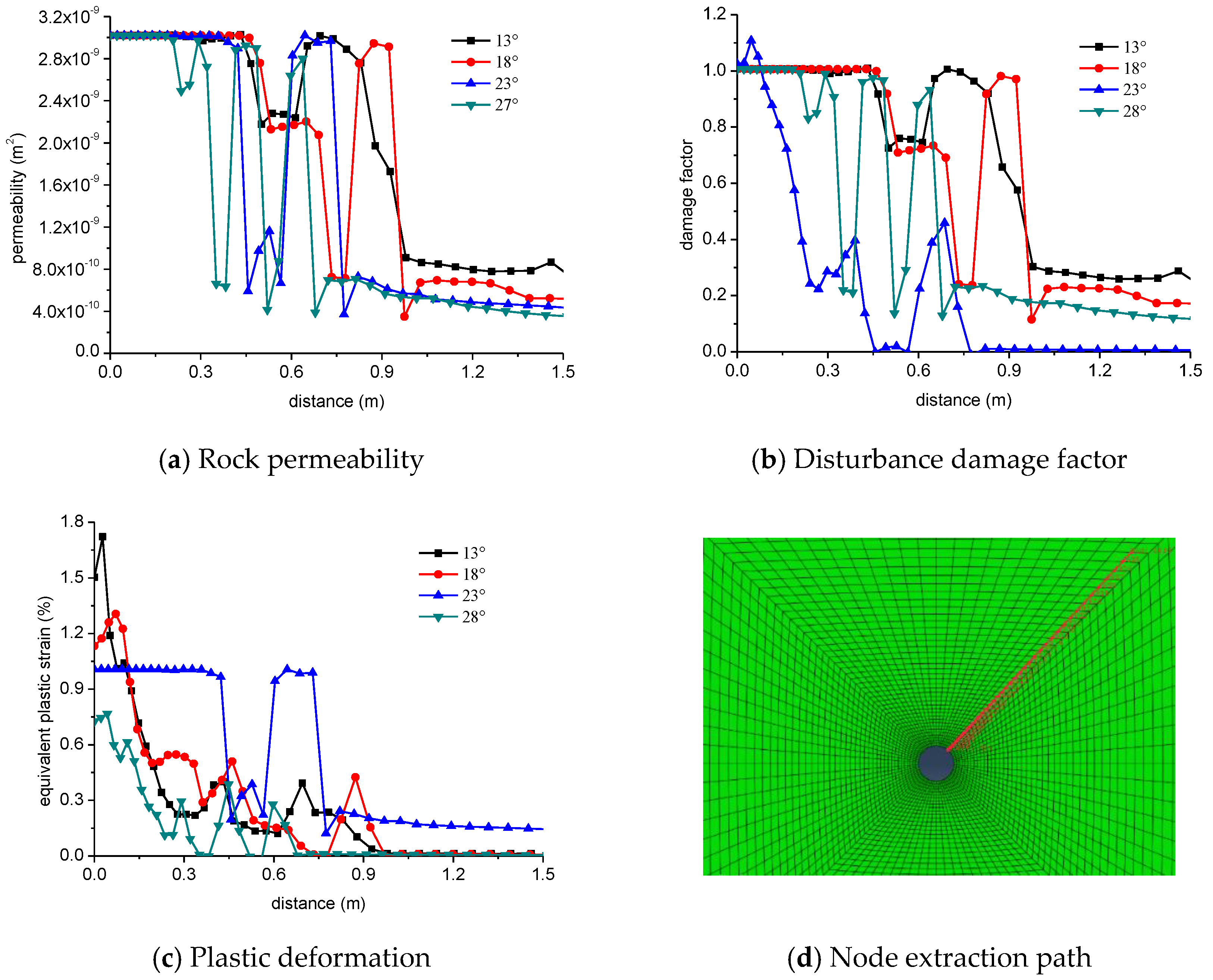
4.3. Effect of the Internal Friction Angle of Rock

The internal friction angle of rock is a key parameter in the Mohr–Coulomb yield criterion for borehole stability. The effect of the internal friction angle of rock of 13°, 18°, 23°, and 28° on borehole instability is simulated.
The cloud picture of the equivalent plastic strain around the borehole under different internal friction angles of rock is shown in Figure 9. As the internal friction angle increases, the equivalent plastic strain area increases, and the bifurcation is enhanced. Under the internal friction angle of 28°, a strong plastic strain area occurs in the y direction, a ‘mantis’ shape occurs (Figure 7b,c), and the bifurcation corresponds to the whisker, which is the shear failure area. Under the low internal friction angle of rock, the equivalent plastic strain area shows a chaotic feature, with a weak elongated plastic strain area along the diagonal direction.
The cloud picture of the damage factor around the borehole under different internal friction angles of rock is shown in Figure 10. As the internal friction angle, the damage area increases, and the bifurcation characteristics are enhanced. Under the friction angle of 28°, an obvious bifurcation occurs in the y direction, and the damage degree approaches 1, indicating shear collapse failure around the borehole. Under the low internal frictional angles, a narrow and long damaged area occurs in the sub-diagonal direction.
The rock permeability, disturbance damage factor, and equivalent plastic strain along the nodal path are shown in Figure 11. As the distance from the borehole increases, the rock permeability, disturbance damage factor, and equivalent plastic strain show a decreasing and fluctuation trend, indicating the heterogeneous damage features.

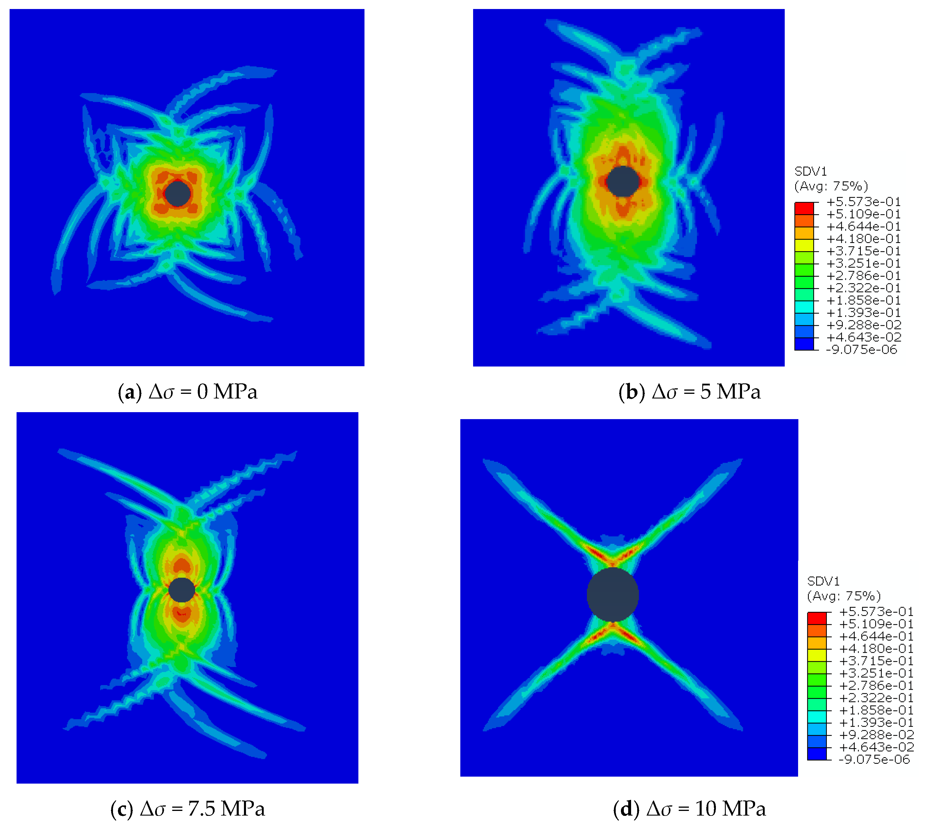
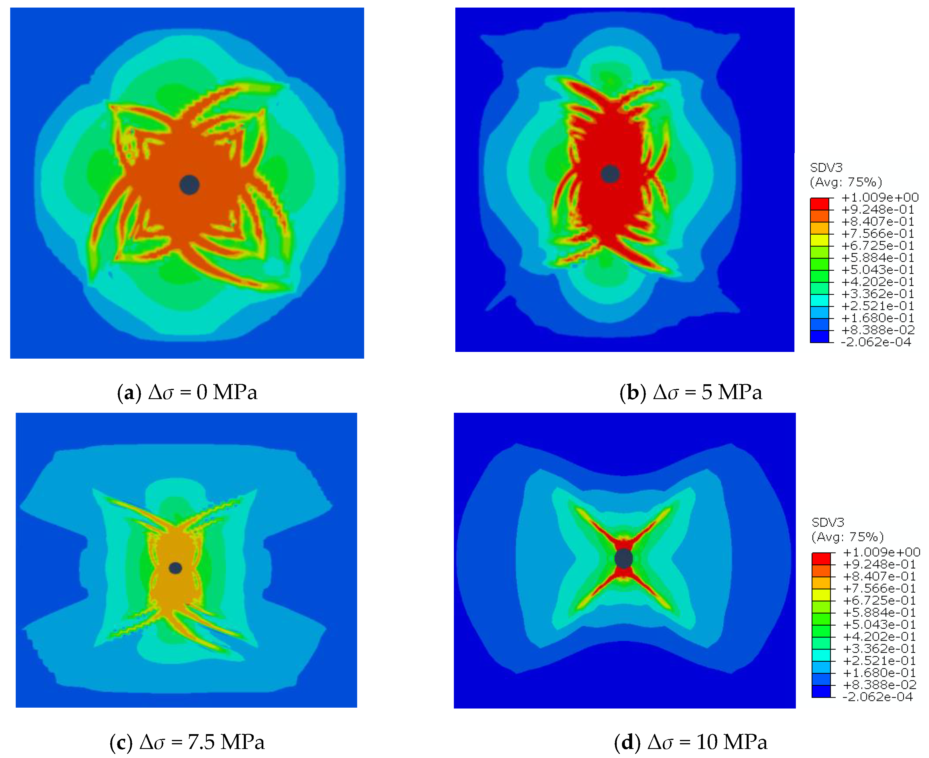
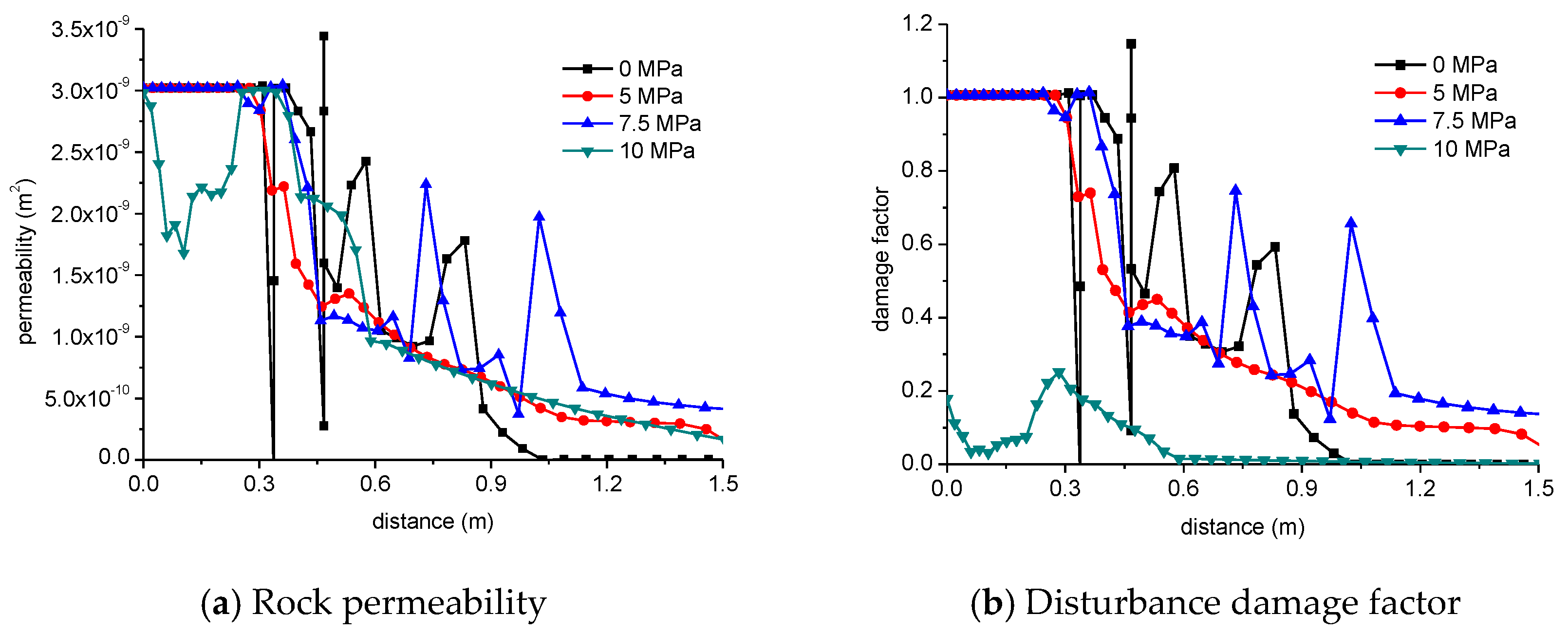
4.4. Effect of Borehole Pressure

During drilling, the drilling fluid within the borehole generates hydrostatic pressure on the borehole wall and causes compression stress on the borehole wall. The effect of the borehole pressure of 3.5 MPa, 4 MPa, 4.5 MPa, and 5 MPa on borehole instability is simulated.
The cloud picture of equivalent plastic strain around the borehole under drilling fluid static pressure is shown in Figure 12. As the hydrostatic pressure increases, the equivalent plastic strain area is enlarged, and the bifurcation characteristics are enhanced. When the hydrostatic pressure is 5 MPa, several bifurcated plastic strain regions occur in the y axis. Under the low borehole pressure, the bifurcation occurs only in the y direction, and shear failure occurs along the y axis.
The cloud picture of the disturbance damage factor around the borehole under drilling fluid column pressure is shown in Figure 13. As the drilling fluid static pressure increases, the damaged area is enlarged, and the bifurcation characteristics are enhanced. When the drilling fluid hydrostatic pressure is 5 MPa, multiple bifurcated damage zones occur in the y direction, indicating that increasing the drilling fluid density promotes shear damage near the borehole and borehole instability.
The rock permeability, disturbance damage factor, and plastic strain area with distance from the borehole along the direction of the node path are shown in Figure 14. As the distance from the borehole increases, the permeability, disturbance damage factor, and plastic strain gradually decrease. Under the low hydrostatic pressure of drilling fluid, the rock permeability, disturbance damage factor, and equivalent plastic strain fluctuate slightly, and the damage position is determined. Under the high borehole pressure, the rock permeability, disturbance damage factor, and plastic strain area fluctuate significantly. The degree of damage varies in different locations, corresponding to multiple bifurcation positions on the cloud picture.

5. Conclusions

Based on the DSC, we carried out a finite element hydro-mechanical coupling model of borehole instability by introducing the disturbance factors into the Mohr–Coulomb yield criterion and writing the subroutine for the field variables. The model considers elastic–plastic deformation, the damage distribution area, and the variation of rock porosity and permeability with the disturbance area in borehole instability. The following conclusions can be drawn:
(1)
The finite element numerical simulation results show that borehole stability is related to the action time of drilling fluid on the wellbore, stress anisotropy, internal friction angle of rock, and borehole pressure. Excessive drilling fluid density and long action time between the drilling fluid and the borehole should be avoided. Under the small stress anisotropy, shear failure occurs often around the borehole. A high horizontal stress difference restricts shear instability around the borehole. The high internal friction angle of rock enhances shear failure around the borehole in the direction of the maximum horizontal principal stress.
(2)
The equivalent plastic strain zone has a good agreement with the borehole instability disturbance damage zone, and they show the same characteristics. A high internal friction angle of rock, low stress anisotropy, and long action time of the drilling fluid on the wellbore enlarge the plastic zone and disturbance damage zone around the borehole.
(3)
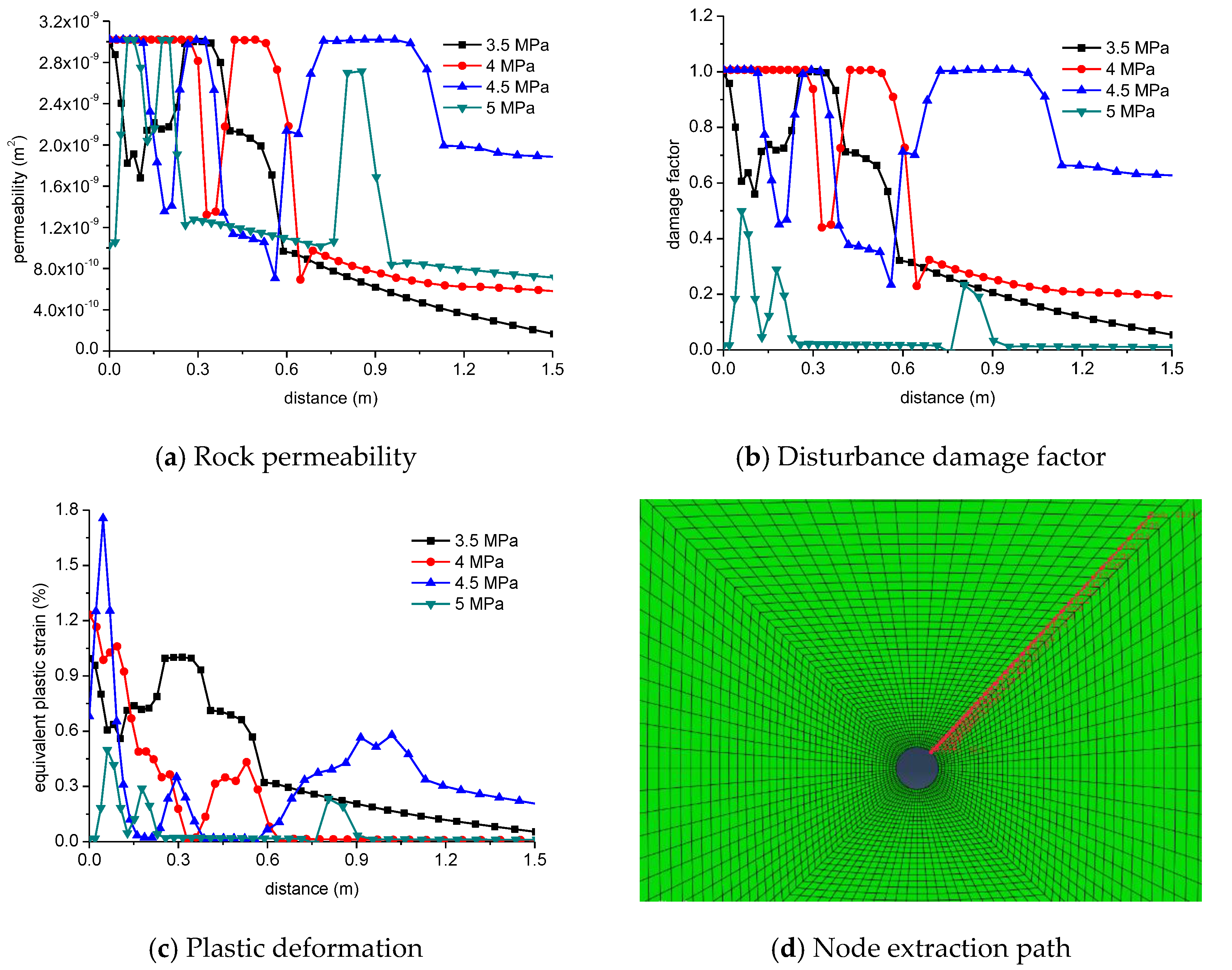
The model of borehole stability considers the variation of rock permeability, rock porosity, and equivalent plastic strain with the disturbance damage factor. Under the large borehole pressure and the low stress anisotropy, the rock permeability, the disturbance damage factor, and the equivalent plastic strain show fluctuation characteristics, which is due to the different damage magnitudes. When considering the internal friction angle of rock, the rock permeability, disturbance damage factor, and equivalent plastic strain area show fluctuation characteristics.
(4)
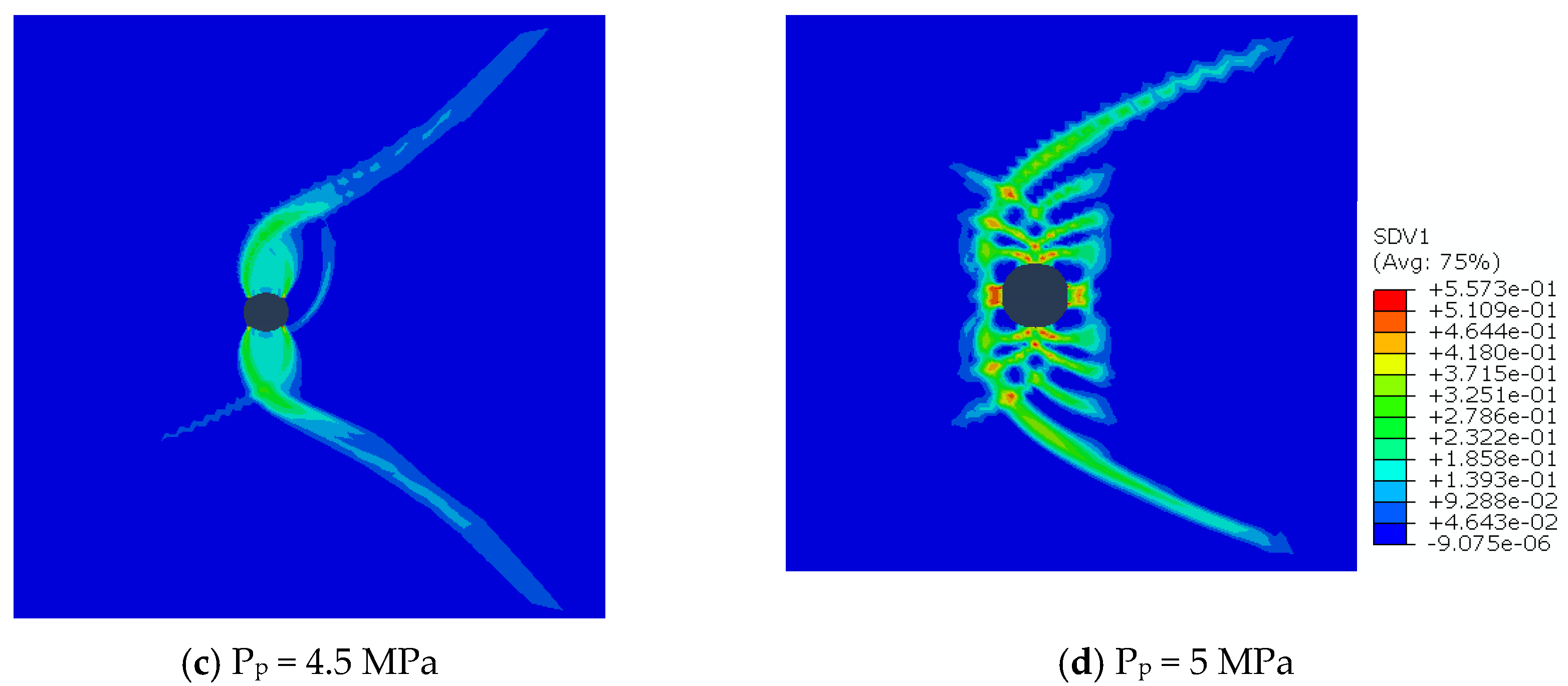
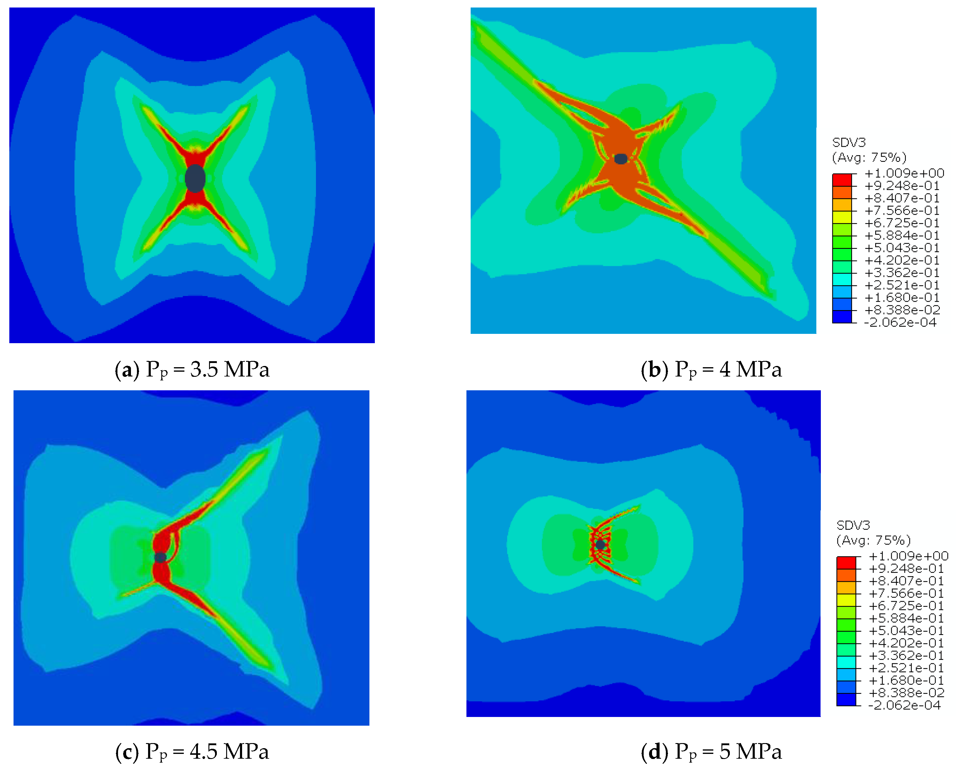
Under the large internal friction angle of rock, a strong equivalent plastic strain zone and a disturbance damage zone occur in the direction of the maximum horizontal principal stress, and they correspond to the mantis shape. The bifurcation corresponds to the whisker, which is the shear failure area. Under the low internal friction angle of rock, the equivalent plastic strain and disturbance damage region show chaotic features, and an elongated equivalent plastic strain region occurs along the diagonal.

Author Contributions

Conceptualization, Z.Q. and B.Y.; methodology, D.W. and Q.S.; software; validation, W.Z.; data curation, Y.Z. and Z. R; writing—original draft preparation, D.W.; writing—review and editing, D.W. and Z.R.; supervision, Z.Q. All authors have read and agreed to the published version of the manuscript.

Funding

The authors would like to give their sincere gratitude to the Beijing Natural Science Foundation Project (No. 3222030); the National Natural Science Foundation Project (No. 51936001, No. 51974255 and No. 51804258); the Scientific Research Project of Beijing Educational Committee (KZ202110017026); and The Key Laboratory of Well Stability and Fluid & Rock Mechanics in Oil and Gas of Shaanxi Province (No. WSFRM20210201002) for their financial support.

Institutional Review Board Statement

Not applicable.

Informed Consent Statement

Not applicable.

Data Availability Statement

Datasets related to this article can be found by contacting the corresponding author.

Conflicts of Interest

The authors declare no conflict of interest.

References

  1. Yu, M.; Chen, G.; Chenevert, M.E.; Sharma, M.M. Chemical and Thermal Effects on borehole stability of Shale Formations. In Proceedings of the SPE Annual Technical Conference and Exhibition, New Orleans, LA, USA, 30 September–3 October 2001. [Google Scholar]
  2. She, H.; Hu, Z.; Qu, Z.; Zhang, Y.; Guo, H. Determination of the Hydration Damage Instability Period in a Shale Borehole Wall and Its Application to a Fuling Shale Gas Reservoir in China. Geofluids 2019, 2019, e3016563. [Google Scholar] [CrossRef]
  3. Han, Q.; Qu, Z.; Ye, Z. Research on the Mechanical Behaviour of Shale Based on Multiscale Analysis. R. Soc. Open Sci. 2018, 5, 181039. [Google Scholar] [CrossRef] [PubMed]
  4. Freij-Ayoub, R.; Tan, C.; Clennell, B.; Tohidi, B.; Yang, J. A borehole stability Model for Hydrate Bearing Sediments. J. Pet. Sci. Eng. 2007, 57, 209–220. [Google Scholar] [CrossRef]
  5. Zhang, J.; Bai, M.; Roegiers, J.-C. Dual-Porosity Poroelastic Analyses of borehole stability. Int. J. Rock Mech. Min. Sci. 2003, 40, 473–483. [Google Scholar] [CrossRef]
  6. Salehi, S.; Hareland, G.; Nygaard, R. Numerical Simulations of borehole stability in Under-Balanced-Drilling Wells. J. Pet. Sci. Eng. 2010, 72, 229–235. [Google Scholar] [CrossRef]
  7. Desai, C.C. A Consistent Finite Element Technique for Work-Softening Behavior; University of Texas: Austin, TX, USA, 1974. [Google Scholar]
  8. Desai, C.S.; Ma, Y. Modelling of Joints and Interfaces Using the Disturbed-State Concept. Int. J. Numer. Anal. Methods Geomech. 1992, 16, 623–653. [Google Scholar] [CrossRef]
  9. Katti, D.R.; Desai, C.S. Modeling and Testing of Cohesive Soil Using Disturbed-State Concept. J. Eng. Mech. 1995, 121, 648–658. [Google Scholar] [CrossRef]
  10. Desai, C.S.; Samtani, N.C.; Vulliet, L. Constitutive Modeling and Analysis of Creeping Slopes. J. Geotech. Eng. 1995, 121, 43–56. [Google Scholar] [CrossRef]
  11. Desai, C.S.; Toth, J. Disturbed State Constitutive Modeling Based on Stress-Strain and Nondestructive Behavior. Int. J. Solids Struct. 1996, 33, 1619–1650. [Google Scholar] [CrossRef]
  12. Desai, C.; Park, I.; Shao, C. Fundamental yet Simplified Model for Liquefaction Instability. Int. J. Numer. Anal. Methods Geomech. 1998, 22, 721–748. [Google Scholar] [CrossRef]
  13. Pal, S.; Wathugala, G.W. Disturbed State Model for Sand-Geosynthetic Interfaces and Application to Pull-out Tests. Int. J. Numer. Anal. Methods Geomech. 1999, 23, 1873–1892. [Google Scholar] [CrossRef]
  14. Fan, R.-D.; Liu, M.; Du, Y.-J.; Horpibulsuk, S. Estimating the Compression Behaviour of Metal-Rich Clays via a Disturbed State Concept (DSC) Model. Appl. Clay Sci. 2016, 132–133, 50–58. [Google Scholar] [CrossRef]
  15. Ouria, A. Disturbed State Concept–Based Constitutive Model for Structured Soils. Int. J. Geomech. 2017, 17, 04017008. [Google Scholar] [CrossRef]
  16. Ghazavi Baghini, E.; Toufigh, M.M.; Toufigh, V. Analysis of Pile Foundations Using Natural Element Method with Disturbed State Concept. Comput. Geotech. 2018, 96, 178–188. [Google Scholar] [CrossRef]
  17. Wu, G.; Zhang, L. Analysis on post-failure behaviors of rock in uniaxial compression using disturbed state concept theory. Chin. J. Rock Mech. Eng. 2004, 10, 1628–1634. [Google Scholar] [CrossRef]
  18. Zheng, J.; Ge, X.; Sun, H. Application of disturbed state concept to issues in geotechnical engineering. Chin. J. Rock Mech. Eng. 2006, 25, 3456–3462. [Google Scholar]
  19. Zheng, J.; Ge, X.; Sun, H. Meso analysis for rationality of disturbed state concept theory on utilization of hardening model for softening response depiction. Rock Soil Mech. 2007, 28, 127–132. [Google Scholar]
  20. Zhang, X.; Wang, C. Study of creep constitutive model of structural soft soil based on the disturbed state concept. China Civ. Eng. J. 2011, 44, 81–87. [Google Scholar]
  21. Fu, P.; Chu, X.; Yu, C.; Xu, Y.; Qu, W. Simulation of Strain Localization of Granular Materials Based on Disturbed State Concept. J. South China Univ. Technol. Sci. Ed. 2014, 42, 59–69+76. [Google Scholar]
  22. Yang, J.; Yin, Z.; Huang, H.; Jin, Y.; Zhang, D. Bounding surface plasticity model for structured clays using disturbed state concept-based hardening variables. Chin. J. Geotech. Eng. 2017, 39, 554–561. [Google Scholar]
  23. Huang, M.; Jiang, Y.; Wang, S.; Deng, T. Identification of the creep model and its paramters of soft rock on the basis of disturbed state concept. Chin. J. Solid Mech. 2017, 38, 570–578. [Google Scholar]
  24. Zou, Y.; Wei, C.; Chen, H.; Zhou, J.; Wan, Y. Elastic-plastic model for gas-hydrate-bearing soils using disturbed state concept. Rock Soil Mech. 2019, 40, 2653–2662. [Google Scholar]
  25. Cao, W.; Deng, J.; Liu, W.; Yu, B.; Tan, Q.; Yang, L.; Li, Y.; Gao, J. Pore Pressure and Stress Distribution Analysis around an Inclined borehole in a Transversely Isotropic Formation Based on the Fully Coupled Chemo-Thermo-Poroelastic Theory. J. Nat. Gas Sci. Eng. 2017, 40, 24–37. [Google Scholar] [CrossRef]
  26. Liang, C.; Chen, M.; Jin, Y.; Lu, Y. borehole stability Model for Shale Gas Reservoir Considering the Coupling of Multi-Weakness Planes and Porous Flow. J. Nat. Gas Sci. Eng. 2014, 21, 364–378. [Google Scholar] [CrossRef]
  27. Kang, Y.; Yu, M.; Miska, S.Z.; Takach, N. Borehole Stability: A Critical Review and Introduction to DEM. In Proceedings of the SPE Annual Technical Conference and Exhibition, New Orleans, LA, USA, 4–7 October 2009. [Google Scholar]
  28. Chen, G.; Chenevert, M.E.; Sharma, M.M.; Yu, M. A Study of borehole stability in Shales Including Poroelastic, Chemical, and Thermal Effects. J. Pet. Sci. Eng. 2003, 38, 167–176. [Google Scholar] [CrossRef]
  29. Zeynali, M.E. Mechanical and Physico-Chemical Aspects of borehole stability during Drilling Operations. J. Pet. Sci. Eng. 2012, 82–83, 120–124. [Google Scholar] [CrossRef]
  30. Gao, L.; Shi, X.; Liu, J.; Chen, X. Simulation-based three-dimensional model of wellbore stability in fractured formation using discrete element method based on formation microscanner image: A case study of Tarim Basin, China. J. Nat. Sci. Eng. 2022, 97, 104341. [Google Scholar] [CrossRef]
  31. Ma, T.; Zhang, Y.; Qiu, Y.; Liu, Y.; Li, Z. Effect of parameter correlation on risk analysis of wellbore instability in deep igneous formations. J. Pet. Sci. Eng. 2022, 208, 109521. [Google Scholar] [CrossRef]
  32. Cao, W.; Liu, W.; Liu, H.; Lin, H. Effect of formation strength anisotropy on wellbore shear failure in bedding shale. J. Pet. Sci. Eng. 2022, 208, 109183. [Google Scholar]
  33. Liu, D.; Deng, H.; Zhang, Y. Research on the Wellbore Instability Mechanism of Air Drilling Technology in Conglomerate Formation. Fresen. Environ. Bull. 2020, 29, 600–606. [Google Scholar]
  34. Liu, H.; Cui, S.; Meng, Y.; Li, Z.; Yu, X.; Sun, H.; Zhou, Y.; Luo, Y. Rock mechanics and wellbore stability of deep shale during drilling and completion processes. J. Pet. Sci. Eng. 2021, 205, 108882. [Google Scholar] [CrossRef]
  35. Aslannezhad, M.; Kalantariasl, A.; Keshavarz, A. Borehole stability in shale formations: Effects of Thermal-Mechanical-Chemical parameters on well design. J. Nat. Gas Sci. Eng. 2021, 88, 103852. [Google Scholar] [CrossRef]
  36. AlBahrani, H.; Morita, N. Risk-Controlled Wellbore Stability Criterion Based on a Machine-Learning-Assisted Finite-Element Model. SPE Drill. Completion 2022, 37, 38–66. [Google Scholar] [CrossRef]
  37. Li, J.; Qiu, Z.; Zhong, H.; Zhao, X.; Liu, Z.; Huang, W. Effects of water-based drilling fluid on properties of mud cake and wellbore stability. J. Pet. Sci. Eng. 2022, 208, 109704. [Google Scholar] [CrossRef]
  38. Liu, W.; Lin, H.; Liu, H.; Luo, C.; Wang, G.; Deng, J. Numerical Investigation of Wellbore Stability in Deepwater Shallow Sediments. Geofluids 2021, 2021, 5582605. [Google Scholar] [CrossRef]
  39. Cui, S.; Liu, H.; Meng, Y.; Zhang, Y.; Tao, Y.; Zhang, X. Study on fracture occurrence characteristics and wellbore stability of limestone formation. J. Pet. Sci. Eng. 2021, 204, 108783. [Google Scholar] [CrossRef]
  40. Ding, Y.; Liu, X.; Luo, P. Investigation on influence of drilling unloading on wellbore stability in clay shale formation. Pet. Sci. 2021, 17, 781–796. [Google Scholar] [CrossRef]
  41. Wang, D.; Zhou, F.; Ding, W.; Ge, H.; Jia, X.; Shi, Y.; Wang, X.; Yan, X. A Numerical Simulation Study of Fracture Reorientation with a Degradable Fiber-Diverting Agent. J. Nat. Gas Sci. Eng. 2015, 25, 215–225. [Google Scholar] [CrossRef]
  42. Wang, D.; Zlotnik, S.; Díez, P. A Numerical Study on Hydraulic Fracturing Problems via the Proper Generalized Decomposition Method. CMES Comput. Model. Eng. Sci. 2020, 122, 703–720. [Google Scholar] [CrossRef]
  43. Wang, D.; Ge, H.; Wang, X.; Wang, Y.; Sun, D.; Yu, B. Complex Fracture Closure Pressure Analysis During Shut-in: A Numerical Study. Energy Explor. Exploit. 2022, 40, 014459872210773. [Google Scholar] [CrossRef]
  44. Wang, D.; Dong, Y.; Sun, D.; Yu, B. A Three-Dimensional Numerical Study of Hydraulic Fracturing with Degradable Diverting Materials via CZM-Based FEM. Eng. Fract. Mech. 2020, 237, 107251. [Google Scholar] [CrossRef]
  45. Jaeger, J.C.; Cook, N.G.W.; Zimmerman, R. Fundamentals of Rock Mechanics; John Wiley & Sons: Hoboken, NJ, USA, 2009. [Google Scholar]
Figure 1. Validation examples: (a) numerical solution and analytical solution of Sxx stress component; (b) comparison of numerical simulation and experimental results.
Energies 15 06295 g001
Figure 2. Schematic of the finite element model of borehole stability and mesh division.
Energies 15 06295 g002
Figure 3. Evolution of equivalent plastic strain region (SVD1 represents equivalent plastic strain).
Energies 15 06295 g003
Figure 4. Evolution of damage region (SVD3 represents disturbance damage factor).
Energies 15 06295 g004aEnergies 15 06295 g004b
Figure 5. Rock permeability, disturbance damage factor, and equivalent plastic strain with different distances from the borehole.
Energies 15 06295 g005
Figure 6. Evolution of equivalent plastic strain with the stress difference.
Energies 15 06295 g006
Figure 7. Evolution of disturbance damage factor with different stress differences.
Energies 15 06295 g007
Figure 8. Variation of rock permeability, damage factor, and equivalent plastic strain with different distance.
Energies 15 06295 g008aEnergies 15 06295 g008b
Figure 9. Evolution of equivalent plastic strain region.
Energies 15 06295 g009
Figure 10. Evolution of disturbance damage factor with the internal friction angle of rock.
Energies 15 06295 g010
Figure 11. Variation of rock permeability, damage factor, and equivalent plastic strain with different distance.
Energies 15 06295 g011
Figure 12. Evolution of equivalent plastic strain.
Energies 15 06295 g012aEnergies 15 06295 g012b
Figure 13. Evolution of damage factor with borehole pressure.
Energies 15 06295 g013
Figure 14. Variation of rock permeability, damage factor, and equivalent plastic strain with different distance.
Energies 15 06295 g014
Table 1. Input parameters.
ParametersValue
Porosity/decimal0.05
Poisson’s ratio/decimal0.25
Elastic modulus/GPa34.5
Rock density/kg/m32500
Rock permeability/mD0.001
Tensile strength/MPa6.04
Uniaxial compressive strength/MPa100
Internal friction angle of rock/°33.7
Element damage evolution factor/decimal2
Fluid density/kg/cm31020
Fluid compression coefficient/1/Pa2 × 10−10
Fluid viscosity/mPa·s1.8
Initial formation pressure/MPa28
Maximum horizontal principal stress/MPa40
Minimum horizontal principal stress/MPa30
Borehole radius/m0.1
Injection time/s60
Table 2. Input parameters in finite element simulation of rock borehole instability (Base case).
ParametersValue
Rock elastic modulus/Pa3 × 108
Poisson’s ratio/decimal0.25
Rock permeability/m23 × 10−12
Porosity/decimal0.16
Maximum horizontal principal stress/Pa2.75 × 106
Minimum horizontal principal stress/Pa1.75 × 106
Vertical stress/Pa3.5 × 106
Rock cohesion/Pa3 × 105
RInternal friction angle of rock/°18
Dilation angle of rock/°0
Initial pore pressure/Pa1.5 × 106
Material parameter a/decimal0.2
Publisher’s Note: MDPI stays neutral with regard to jurisdictional claims in published maps and institutional affiliations.

