Article

Forward Modeling of Natural Fractures within Carbonate Rock Formations with Continuum Damage Mechanics and Its Application in Fuman Oilfield

1
School of Petroleum Engineering, Changjiang University, Wuhan 430100, China
2
Research Institute of Engineering Technology, CNPC West Drilling, Karamay 834000, China
3
Institute of Reservoir Engineering, College of Petroleum Engineering, China University of Petroleum (Huadong), Qingdao 266580, China
4
Exploration Division, PetroChina Xinjiang Oilfield Company, Karamay 834000, China
5
Changqing Drilling Subcompany, CNPC Chuanqing Drilling, Xi’an 710016, China
*
Author to whom correspondence should be addressed.
Energies 2022, 15(17), 6318; https://doi.org/10.3390/en15176318
Submission received: 11 August 2022 / Revised: 24 August 2022 / Accepted: 26 August 2022 / Published: 30 August 2022
(This article belongs to the Special Issue Sustainable Production and Environmentally Responsible Consumption)

Abstract

:
Accurate information about the distribution of natural fractures is a key factor for the success of the exploration and development of oil and gas in carbonate rock formations. Forward modeling of natural fractures generated by tectonic movement within carbonate rock formations was investigated by jointly using the continuum damage model and finite element numerical technology. Geological analysis of natural fractures was used as the basis of the geomechanical finite element calculation. A workflow of numerical calculations for natural fractures was proposed. These achievements were applied to investigate natural fractures’ distribution within Ordovician carbonate rock formations of the Fuman Oilfield, Xinjiang, in the west of China. Finite element sub-modeling technology was used to further investigate natural fractures within key target reservoir formations with a finer mesh. The contour of natural fractures represented by the localization band of continuum damage variables was obtained. A comparison of the numerical results of the natural fractures’ distribution represented by continuum damage variables with those of natural fractures interpreted from seismic data shows that: (1) the numerical solution of natural fractures matches the measured data, and their orientations are in good accordance; (2) their distribution and locations are basically the same, with some small differences in local details; (3) the numerical results indicate that the maximum value of the damage variable SDEG within the zones of natural fractures is 0.2686, and the widths of the bands of natural fractures/faults are in the range of 500 m to 1000 m. Validation of the results of the distribution of natural fractures was performed indirectly via the distribution of the minimum horizontal stress gradient ShG.

1. Introduction

Information about the distribution of natural fractures has special significance in the development of oil and gas resources within carbonate rock formations in the Tarim Basin [1,2,3]. Oil existing in the carbonate reservoirs in the Tarim Basin was filled into the current locations from underlying formations. These carbonate rock reservoirs are not source rock [3]. Because oil and gas resources from carbonate rock reservoirs in the Fuman Oilfield only exist in natural fractures, distribution information about natural fractures determines the selection of the location of a wellbore trajectory. In addition, in the exploration and development of limited oil and gas resources such as shale oil and gas, as well as that of the conglomerate reservoir in the Junggar Basin [4], information about the distribution of natural fractures within a reservoir is one of the factors that determines the success of hydraulic fracturing. Therefore, it is one of the research hotspots in the field of petroleum engineering to accurately obtain the information on the distribution of natural fractures within carbonate rock formations and other tight oil and gas formations.
A conventional method for natural fracture interpretation and identification in engineering is to use seismic data to identify the distribution of natural fractures/faults in a target reservoir. It has been used widely in the current petroleum industry. However, its weakness is the need for obvious amounts of displacement of a fault (hereby, the term ‘displacement of a fault’ represents the amount of displacement discrepancy across the fault). When the displacement of a fault is not obvious, it is difficult to accurately identify natural fractures by using seismic data.
In addition to the aforementioned technology of identifying natural fractures and faults by the interpretation of seismic data, there are a variety of technologies for the identification and calculation of natural fractures. An effective method adopted by the international engineering community is to calculate the process of orogenic tectonic movement experienced by a carbonate rock formation by using geomechanical forward modeling combined with the formation sedimentary history, and to obtain the formation and distribution of faults/fracture zones [5,6,7].
In this paper, the forward modeling method of geomechanics and continuum damage mechanics is used to predict the distribution of faults and natural fractures in carbonate rock formations in the Fuman area according to the sedimentary history/generation sequence and the history of crustal movement/main activities of orogeny.
Natural fractures in Ordovician carbonate rock formations exist in the form of sets of fractures in rock as quasi-brittle material, not in the form of a single fracture. For sets of natural fractures in rock as quasi-brittle material, the model of fracture mechanics is unable to describe the mechanical behavior of a rock formation with multiple sets of natural fractures; instead, continuum damage mechanics is a suitable mechanical tool to describe the behavior of sets of this type of natural fracture in rock as quasi-brittle material [8,9].
Damage mechanics theory uses damage variables to mathematically formulate the crushing degree of materials [7]. A damage variable is particularly suitable for quantifying the degree of crushing/fragmentation of natural fractures of rock: 0 indicates that the rock is intact and 1 indicates that it is extremely broken. The examples presented in this paper show that the degree of crushing/fragmentation of rock with natural fractures is in the range of 0.3 to 0.
In the following sections, the following content is presented:
  • Firstly, we introduce the calculation principle and process of the numerical solution of natural fracture distribution by using the method of geomechanics and damage mechanics.
  • Then, we introduce the 3D geological model based on the interpretation of seismic data of the Fuman Oilfield. A finite element model for this block is established on the basis of this geological model: it includes the model grid, load and boundary conditions, and material model of damage mechanics, which includes damage evolution, etc., material parameters, and other model details.
  • At the end, the numerical results of the contour of damage variables and the analysis of natural fractures are presented.
It should be noted that the distribution of natural fractures/faults obtained by the method of continuum damage mechanics with the calculation of forward modeling does not include natural fractures in the form of karst caves. In addition, natural fractures obtained by forward modeling technology include not only natural fractures for a fault with a width of several kilometers, but also small fractures with a width at the meter scale, as well as micro-fractures.

2. Materials and Methods

2.1. Principle of Calculation and Workflow

Figure 1 shows the flow chart for performing the numerical solution of the natural fractures’ distribution by using the integrated method of geomechanics and damage mechanics. This process includes the following steps.
(1)
Analysis of geological model. Analyze the sedimentary history and formation’s sequence, establish the geometry of each formation in the target block, and calculate the values of parameters of mechanical properties.
(2)
Analysis of stratigraphic tectonic movement and characteristics of stress field. For a given tectonic movement (here, it is the middle Caledonian period for an Ordovician formation), determine the values of displacement vector or stress field distribution according to the history of tectonic movement/main events in orogeny. This is an iterative process, which requires the adjustment of the parameter values of related parameters according to the damage variable field distribution of numerical results and the known natural fracture difference information observed.
(3)
Finite element model for calculation of natural fractures by forward modeling. The formation and deformation generated by tectonic movements are calculated by geomechanical numerical calculation tools, and the distributions of natural fractures/faults are simulated by a material model of mechanical damage.
(4)
Submodels are built and further numerical calculations are performed for key target formations. In key target formations, submodel technology is used to improve the accuracy of the numerical results of the natural fracture distribution with a refined mesh.
(5)
Parameter identification for the finite element model of the target block. Values of parameters of the finite element model for the target block include parameters of loads and boundary conditions, as well as parameters of the plastic damage model of the carbonate rock. By comparison, between the numerical results of the distribution of the main large-scale fractures/faults and the results of the distribution of the observed faults/fractures, modification to the initial input data of the model used can be performed for better fitting between the numerical solution and measured solution for the distribution of natural fractures. Iteratively modify the values of input data with reference to the comparison results until the calculation results are consistent.
The right-hand side of Figure 1 is an explanation of the functions of steps 1 to 5 described in the left-hand side. The right-hand side is parallel to the left-hand side and thus they do not connect to each other. The first four steps in the workflow shown in Figure 1 are actually the process of establishing the geomechanical model, as well as a model of the damage mechanics, identifying the model parameters, and determining the values of loads and material parameters. A global model is used in this process. The last step is to apply the calibrated model to predict the three-dimensional distribution of natural fractures. A submodel with a finer mesh is used in this process. Target reservoir formation is the object of analysis in this step.

2.2. Geological Model and Natural Fracture Analysis of Target Formation

The reservoir in the Fuman Oilfield is a carbonate rock reservoir that consists of natural fractures, faults, and karst caves. The reservoir is buried at a true vertical depth (TVD) of value 7500–8800 m and is an ultra-deep formation. Preliminary geological analysis indicates that the horizon of the reservoir formation is relatively smooth, the fault drop is small, and the identification accuracy of natural fractures/fault zones obtained by seismic data interpretation is relatively low. The characteristics of the fault structure and natural fractures in the Fuman area have been the focus of regional geological research in recent years. Several researchers have dedicated efforts to these topics [10,11], and the research results obtained by using different technical methods vary and have their own characteristics.
Despite the works reported in the aforementioned references, there are still problems to be solved in the research on the classification of natural fractures in the Fuman Oilfield, as well as its mechanical characteristics: (1) the classification of natural fractures in Ordovician carbonate reservoirs is not detailed enough—there are multiple tectonic movements related to these fractures, but their impacts on these fractures have not been investigated; (2) the mechanical characteristics of these tectonic movements are not very clear—most of the existing conclusions on these tectonic movements are aimed at the model on the basin scale and are qualitative estimations—and there is a lack of quantitative analysis.
The difficulties in determining the mechanical characteristics of natural fractures in the Fuman Oilfield are as follows: (1) the characteristics of the distribution of natural fractures within carbonate rock formations are complicated, and there are few data from experimental measurements; (2) this research content involves many aspects, such as sedimentary history and orogeny, with many uncertain factors and great difficulty; (3) related research needs to include a three-dimensional numerical simulation with a large amount of calculations and more complex material modeling technology, which is difficult to carry out.
With the rapid development of technology for geological measurement and computation, the technology for modeling and analyzing a three-dimensional geological model and mechanical model of a target block of an oilfield has seen great progress in recent years, which provides a good technical basis for solving the aforementioned problems. In Section 2.2.1, the three-dimensional geological model of block F8B in the Fuman Oilfield is presented first. Then, information on the natural fracture analysis of each layer in this block is introduced. Next, we focus on the Ordovician carbonate target layer and provide the characteristics of the natural fracture system in the target layer.

2.2.1. 3D Geological Model of Block F8B in Fuman Oilfield

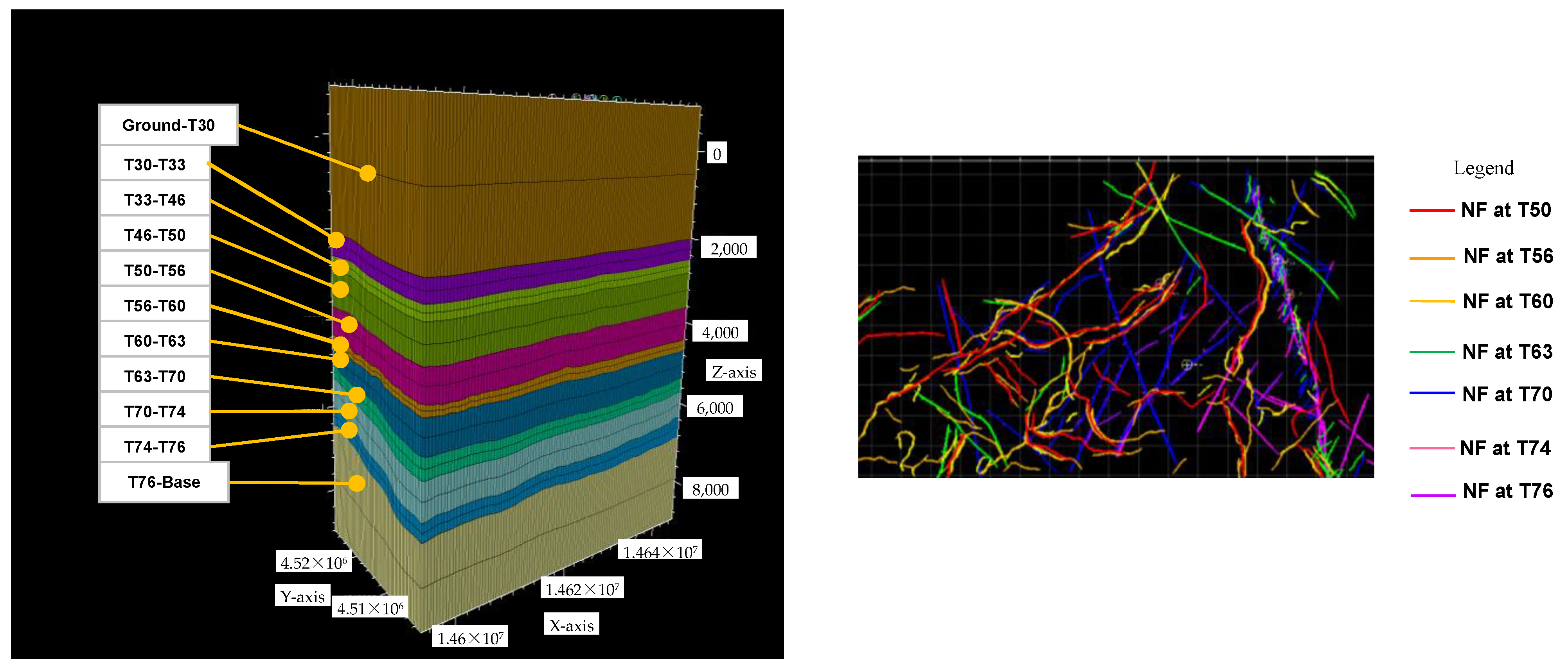
Variation in the depth of the formation top of the target reservoir is relatively smooth. Figure 2 shows the three-dimensional geological model of block F8B in the Fuman Oilfield based on seismic data and formation horizon information obtained through well drilling (pipe-stuck was encountered when drilling across the interface between two types of formations at some wells; mud-log was performed at some wells to confirm the locations of these interfaces). The length, width, and height of the geological model shown in Figure 2 are 55 km, 26 km, and approximately 9980 m, respectively. The surface elevation is approximately 985 m, which is nearly flat. The lowest layer is a layer added to introduce displacement constraints to the model, and the lower bottom surface is set as a plane.
The model consists of 11 layers of rock formations, which are bounded by the geological stratification interface: layer-1 is from the ground surface to the T30 interface; layer-2 is from the T30 to T33 interface; and layer-3 to layer-11 are formed by the following horizons in pairs, respectively: T33–T46 interfaces; T46–T50 interfaces; T50–T56 interfaces; T56–T60 interfaces; T60–T63 interfaces; T63–T70 interfaces; T70–T74 interfaces; T74–T76 interfaces; and T76 interface—bottom plane. There are 11 layers of rock formations in total. Layers from the T30 to T76 interfaces are the layers determined with the interpretation of seismic data. In the target block, F8B, the layer of the Ordovician carbonate rock formation, is located in the T74–T76 layer, with a TVD value of approximately 7000–7600 m.

2.2.2. Analysis of Natural Fractures within Each Layer

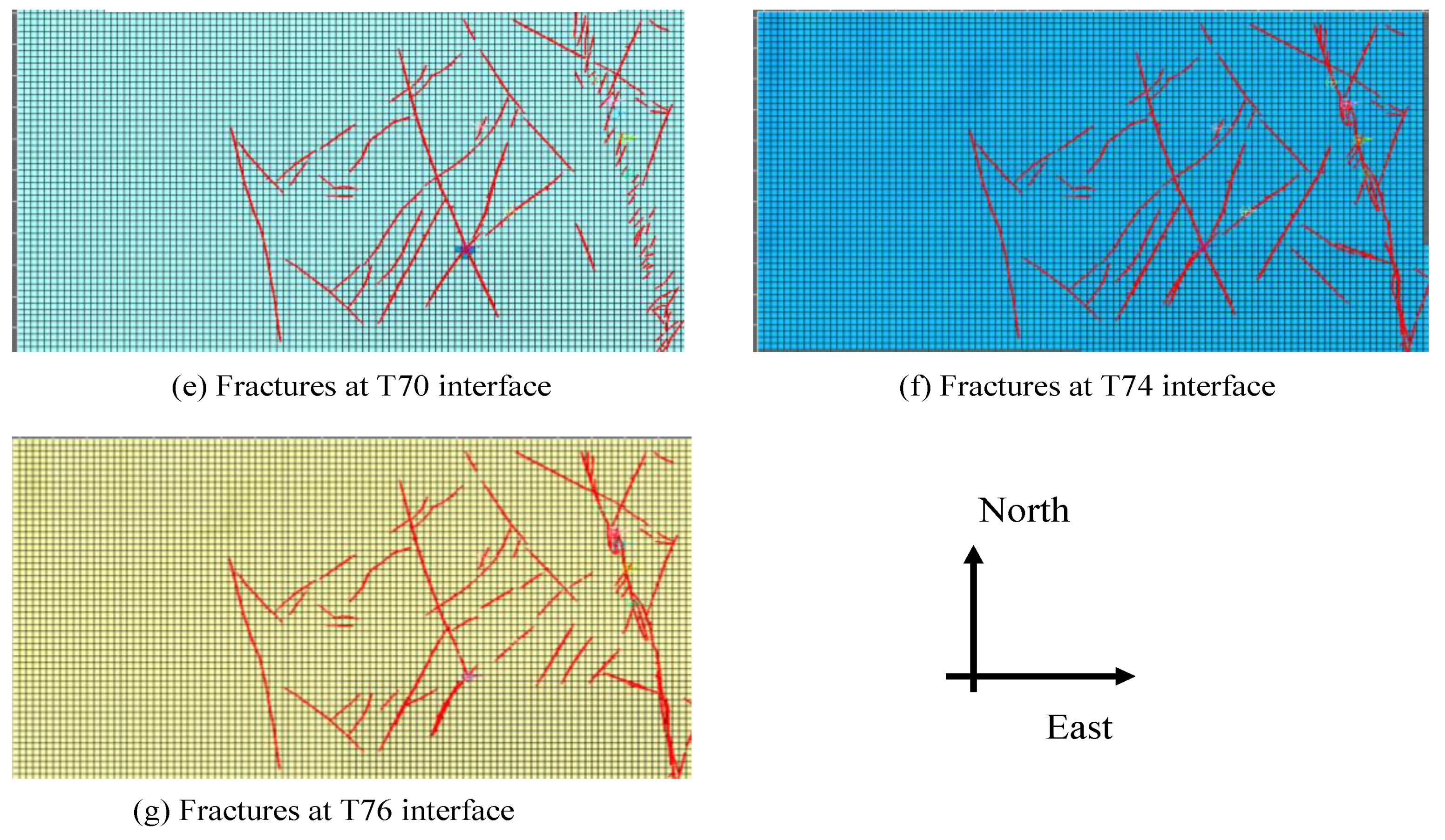
The target layer of the Ordovician carbonate rock formation is the one bounded by the T74 to T76 interfaces below 7000 m, as shown in Figure 2. In order to minimize the cost of computation, details of the geological structures from the ground surface to a depth of 3000 m are omitted, as they would introduce trivial inaccuracy. The left-hand section of Figure 2 shows the horizon interfaces from T30 to T76 interpreted with seismic data, and the right-hand section shows the plane view of the distribution of the natural fracture lines of each layer superimposed together. Figure 3 is a separate display of the natural fracture lines on each horizon interface.
Different colors in Figure 3a–g represent 7 sets of natural fractures of formation layers at different depths. The curves shown in Figure 3 are natural fractures obtained with seismic data interpretation. Combined with the azimuth directions of each set of natural fractures and the penetration degree of natural fractures in different rock formations, natural fractures within these carbonate rock formations of the Ordovician reservoir can be classified into five groups as follows:
(1)
Natural fractures within the upper layers of formations from the T50 to T60 interfaces form a fracture system with the same sets of values of azimuth angles, as well as the same values of depth of penetration.
(2)
Natural fractures of the formation layer from the T60 to T63 interfaces are the second group.
(3)
Natural fractures at the T70 interface have some characteristics of both its upper formation and the formation from its lower side. The fault on the far right has not formed a north–south connection at this depth of the T70 interface. Formations around this depth belong to the transitional area between 2 different tectonic movements, and fractures within these formations belong to the third group.
(4)
Mudstone of the Sangtamu formation with the T72 interface as its top horizon is a capping layer with fewer natural fractures, which is the fourth group. Distributions of natural fractures are not obvious and thus it is omitted here.
(5)
Natural fractures at the T74 and T76 interfaces belong to the same set of natural fracture systems, which are the fifth group. At this depth, these natural fractures are connected vertically from the top to bottom interfaces within this range of depth. The major large faults/natural fractures run from north to south.
These five groups of natural fractures correspond to different tectonic movements. Most of the natural fractures are close to vertical natural fractures, and the values of their dip angles are within the range of 80~90°. At interface T70 in Figure 3e, there are a number of natural fractures/small faults on the right-hand side of the T70 interface, which are a set of oblique lines. They are obviously different from the natural fractures/faults developed in the lower formation’s interface, such as those shown in Figure 3g, which form a connected curve from north to south.
Figure 3 shows the differences between natural fractures of neighboring different formations. This is the key for deriving the tectonic loading conditions in the geomechanical model later on. With the information presented in Figure 3, the tectonic loading condition in the geomechanical finite element model obtains support from the information on the geology.

2.3. Mechanical Characteristics of Natural Fractures in the Target Carbonate Rock Formations

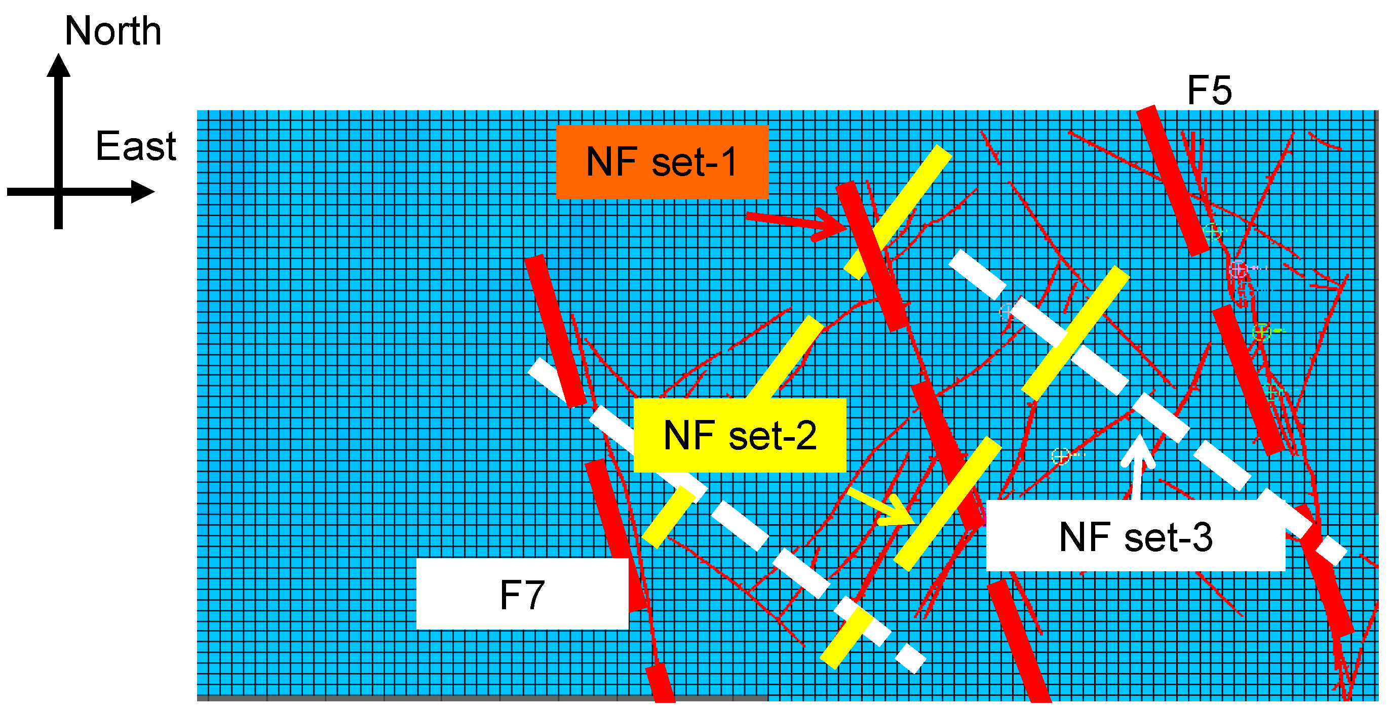
The plane view of the natural fractures at the T74 interface in the Ordovician carbonate reservoir of the F8B block is shown in Figure 4. It is seen from Figure 4 that there are three sets of natural fractures/faults with different orientations.
The first set of natural fractures are long and penetrating natural fractures, including the No. 5 fault and No. 7 fault, which are represented by red dotted lines.
The second set of natural fractures is intermittently distributed, and their orientation is shown in Figure 4 as a yellow straight line.
The third set of natural fractures is intermittently distributed, and its orientation is shown as a white straight line. The third group of natural fractures and the second group of natural fractures are crossed and appear in pairs.
With reference to the aforementioned classification of natural fractures within the target Ordovician reservoir, it can be concluded that (1) natural fractures of set-1 of the Ordovician reservoir are tensile and shear fractures corresponding to tensile loading from tectonic movement; (2) natural fractures of set-2 and set-3 are fractures produced by compression from tectonic movement, and they correspond to compressive loading conditions.

2.4. Analysis of Mechanism of Natural Fractures Generated by Tectonic Movement in Carbonate Rock Formation

In order to investigate and verify the mechanism of natural fractures generated by tectonic movement in Ordovician carbonate rock formations, we established an Abaqus finite element model on the basis of the 3D geological model given in Figure 1. By jointly using the forward modeling technology of geomechanics for tectonic movement and technology for modeling fractures with continuum damage mechanics, values of parameters such as the orientation and magnitude of the displacement/strain of tectonic movement are determined by the trial-and-error method. Namely, the values of parameters of displacement/strain are regarded as the correct ones if the numerical results of the distribution of natural fractures are in good accordance with the ones interpreted from seismic data, as shown in Figure 4.
(1)
The Finite Element model
The Ordovician carbonate rock formation has an age between 485 million years and 443 million years [12]. The sedimentary history of the Ordovician carbonate rock formation between the T74 and T76 interfaces, which is the target formation, is from the middle Caledonian stage I to stage II [5,6]. Tectonic movements experienced by this target Ordovician carbonate rock reservoir are mainly those of the middle Caledonian stage I and II. The subsequent tectonic movements also have an impact on the natural fracture distribution of these rock formations, but they are trivial. As shown in Figure 5, in the finite element model for calculating the natural fractures of the target Ordovician carbonate rock formations between the T74 and T76 interfaces, the T72 interface and its overburden rock formations are omitted in the 3D geomechanical model used here. This model has its top and bottom rock formations added to the target Ordovician carbonate rock formations between the T74 and T76 interfaces for the purpose of convenience of boundary conditions. The finite element mesh used here has 38,885 C3D8R elements and 45,696 nodes in total. Although the Tarim Basin’s edge is formed by a set of irregular oblique lines, the plane view of the target block of this finite element model is only a rectangular plane that has regular borders.
Displacement boundary conditions of the model are set as follows: the zero-displacement constraint is applied to the four sides and bottom plane, and the top surface is the surface with traction loads.
Loads of the finite element model include (a) gravity load, including the gravity load of T70–T80 and other rock formations; (b) the traction load on the top surface is set as 50 MPa, which simulates the possible overburden pressure and also plays a role in stabilizing the convergence effect in numerical calculations.
In this calculation, the ‘initial strain method’ is used to simulate the compressive load of tectonic movements. The initial strain method is used to apply an initial strain tensor ε to each Gaussian integration point of the finite element model. Thus, the strain load borne by each point in the formation is applied. Advantages of this method are as follows: (1) it avoids the serious plastic deformation near the loading point caused by the boundary loading method, and (2) the distribution of the contour of damage variables caused by tectonic movement and their magnitude is reasonable.
The tectonic movement in the period of Caledonian stage I and stage II is the compression from basin edges in the northeast direction [5,6]. The exact values of the orientation angle and the magnitude of displacement are not clearly recorded. The method of phenomenon matching needs to be used to determine the value of displacement/strain of tectonic movement in terms of the coincidence between the distribution of natural fractures in the numerical results obtained and the distribution of natural fractures obtained by the interpretation of seismic data.
The ‘initial strain’ method is used to model the values of the orientation and magnitude of strain of the rock caused by tectonic movement [13]. This method applies a non-zero initial strain tensor to simulate the loading of tectonic movement applied to the target formations.
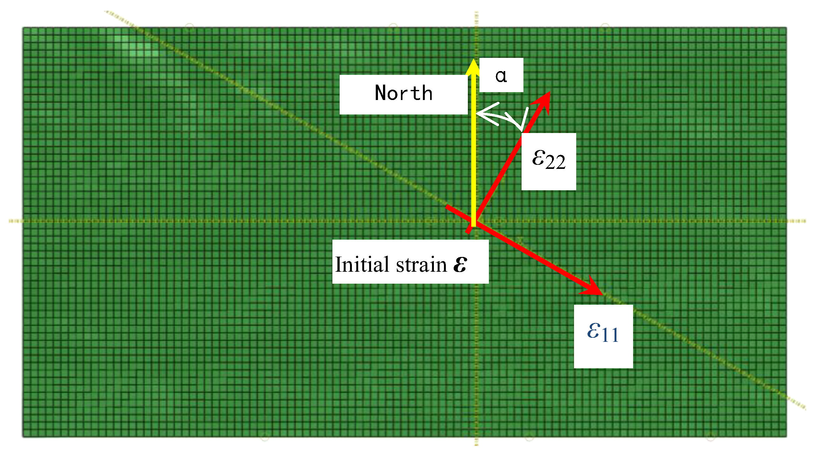
In this calculation, in order to determine the direction of the principal component of the displacement/strain of tectonic movement, the orientation angle of the local principal direction 2 of the initial strain tensor is written as α, as shown in Figure 6. A series of five different values are given to α as follows:
(a) α = 30°; (b) α = 15°; (c) α = 0°; (d) α = −15°; (e) α = −30°
The value of the second principal component of initial strain ε22 in the local principal direction (α = 15°) is taken as a series of different values between 0 and 0.5. The numerical results show that the component ε22 of initial strain is given as ε22 = 0.024, i.e., 2.4%. Values of the initial strain component in other principal directions are set as zero. With these values of parameters as input data, the numerical solution of natural fractures’ distribution obtained with forward modeling of tectonic movement and damage mechanics is in good agreement with the known distribution of natural fractures.
The constitutive model of damage mechanics for carbonate rock that was introduced in reference [9,10,13] is used here to model fractures’ initiation and evolution. In this model of damage mechanics, two scalar damage variables, tensile damage DT and compressive damage DC, are used to represent the damage initiation and evolution mechanisms of rock formations under tectonic loading conditions. The comprehensive damage variable scalar SDEG is used to comprehensively express the material damage degree caused by DT and DC. Theoretical formulation of parameters of this damage mechanics model, including the description of the damage evolution rate and damage initiation criterion, can be seen in the literature [9,10,13]. Values of model parameters are calibrated by the method of ‘trial-and-error’ and phenomenon matching. After a set of trial calculations, values of parameters of the damage evolution law of the Ordovician carbonate rock reservoir were obtained, and they are listed in Table 1 and Table 2. Parameter εi represents the value of inelastic strain, and Dc is the value of the compressive damage variable. These two parameters, listed in Table 1, form a diagram of the damage evolution law under the compressive loading condition. Table 2 refers to damage evolution under tensile loading conditions.

3. Results

3.1. Numerical Solution of Contour of Damage Variable SDEG of the Global Model

The analysis performed in the work reported here is the 3D static finite element calculation of the deformation of target formations. With initial strain as the loading of tectonic movement to the target formations, the numerical results of damage initiation and evolution are presented. The contours of damage variables that represent the distribution of natural fractures are given in Figure 7. The finite element submodel and its results for damage contours are given in Figure 8 and Figure 9.
Figure 7 gives a plane view of the contours of the damage variable SDEG obtained with α = 15° and ε22 = 0.024. Figure 7a shows the contour of damage SDEG at the T74 interface, which is the top of the target formation, and Figure 7b shows the contour of SDEG at the T76 interface, which is the bottom of the target formation. It can be seen that the maximum value of the damage variable SDEG is 0.2566, i.e., the degree of fragmentation of the rock is 25.66%. As can be seen by comparing the contours of SDEG in Figure 7a with the one in Figure 7b, the value of the damage variable SDEG on the T76 interface is slightly larger than that on the T74 interface. The damage localization zone shown in Figure 7 represents the distribution of natural fractures in the formation under loading of tectonic movement. The larger the value of the damage variable SDEG at a nodal point within the finite element model, the higher the degree of fragmentation of natural fractures within carbonate rock formations at this location will be.
By comparing the contour of SDEG in Figure 7 with the natural fracture distribution at the T74 and T76 interfaces shown in Figure 3 and Figure 4, it can be concluded that the numerical solution of natural fractures obtained by the forward modeling of tectonic movement is very close to the results of natural fractures obtained with seismic data interpretation: the values of the orientation of major sets of natural fractures are the same and the details of natural fractures of a smaller size are different.
Therefore, according to the numerical solution of the natural fractures’ distribution shown in Figure 7, it can be concluded that the mechanical characteristics of the tectonic movement that is applied to the Ordovician carbonate rock formation of the T74–T76 interfaces are as follows: (1) it is a compressive load; (2) the value of the orientation angle of the load is α = 15°; and (3) the value of the principal component of the strain tensor generated by tectonic movement is ε22 = 0.024, which is 2.4%. Values of other components of this initial strain tensor are set to zero.

3.2. Submodel and Its Numerical Solution of Damage Field for Distribution of Natural Fractures

Submodeling is a type of numerical technology used in finite element calculations to minimize computational costs while maximizing the accuracy of the numerical solution by refining the mesh size only at the key target region [13]. Definition of the submodel of the finite element model that is used here includes mesh and boundary conditions. The material models and loading conditions of the submodel are the same as those of the global model.
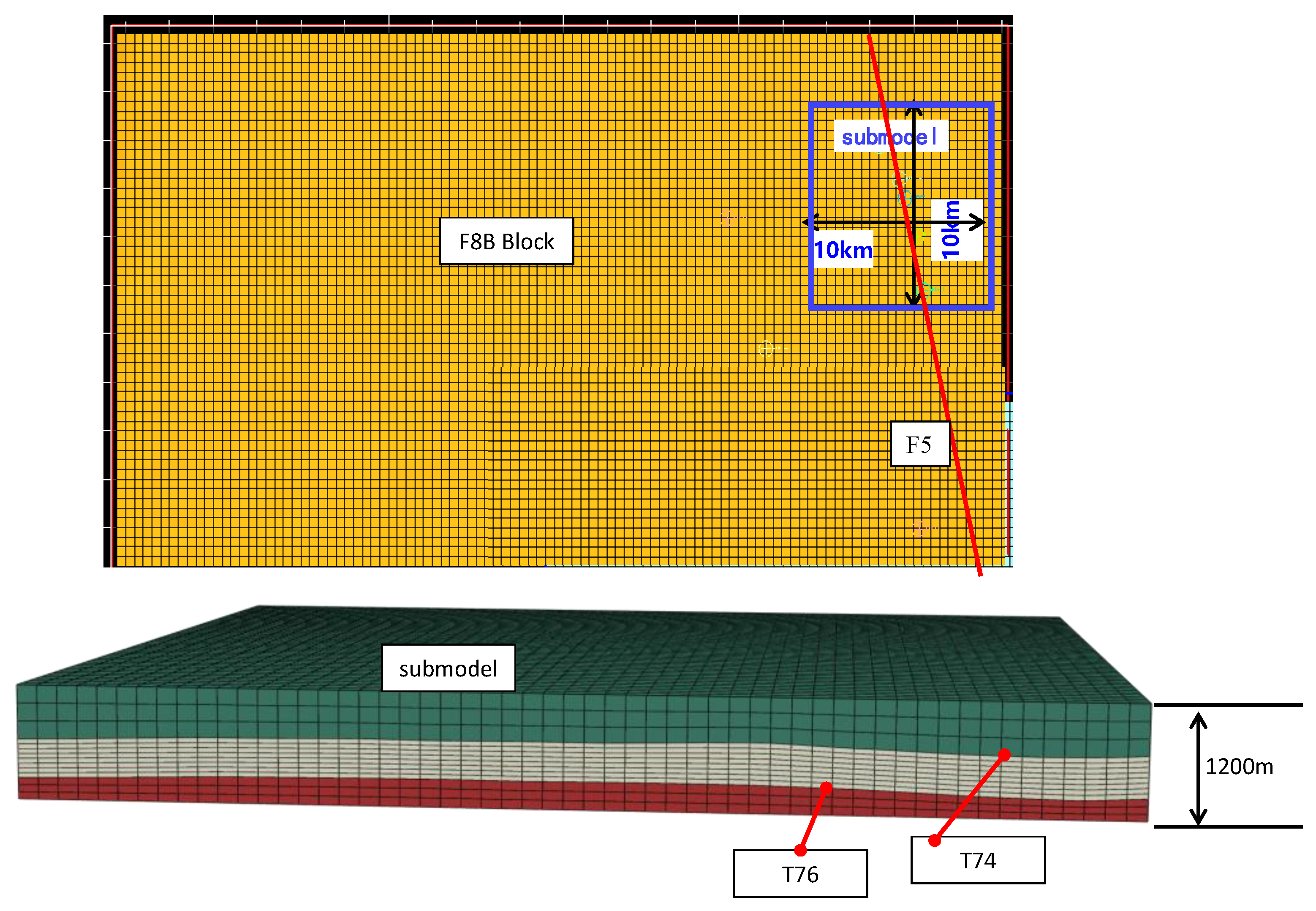
Figure 8 shows the location of the submodel of the key target region in the block F8B and its finite element mesh. The red line in Figure 8 shows the location of the known major fault F5.
The submodel is 10 km long and 10 km wide. Its thickness is 1200 m, including the formation of the Ordovician carbonate reservoir between the T74 and T76 interfaces, the top layer, and the bottom layer, with a total of three layers. Values of element size are 200 m in both length and width and 50 m in the thickness direction. In total, 46,000 nodes and 45,000 C3D8R elements are used to discretize the geometry of the submodel.
The boundary conditions of the submodel are given with values of nodal displacement of the numerical solution of the global model of F8B. They are non-zero displacement boundary conditions, which are subtracted from the numerical solution of the displacement field of the global model of the F8B block shown in Figure 5. Values of material parameters such as the damage evolution law, etc., used in the submodel are the same as those in the global model.
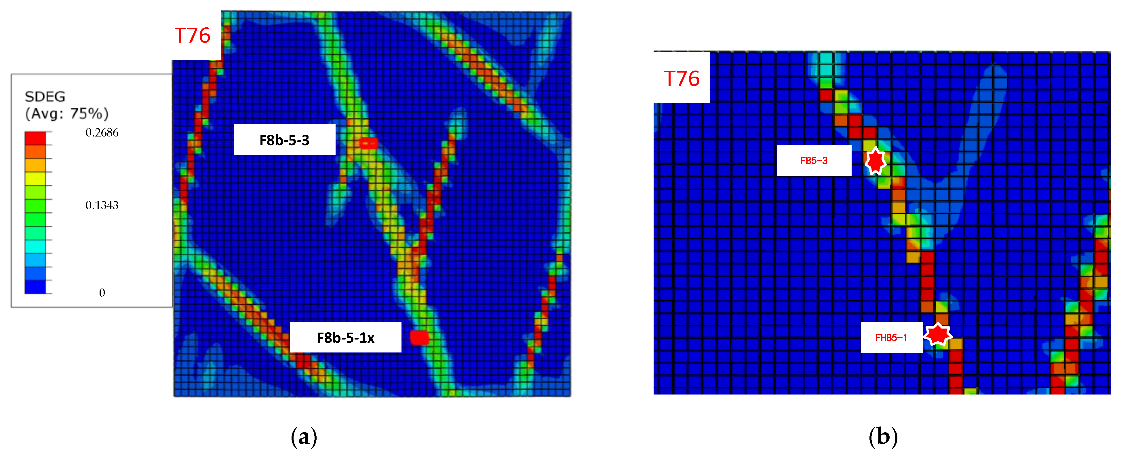
Figure 9a,b show the distribution of natural fractures represented by the contour of the damage variable SDEG obtained with the submodel shown in Figure 8 and that with the global model shown in Figure 5, respectively. The contour is given for values of SDEG of nodal points at the T76 interface.
For brevity, only the contour of the synthetic variable SDEG at the T76 interface, which is the bottom of the target formation, is presented in Figure 9a. The contour of SDEG at the T74 interface, which is the top of the target formation, is similar to the case shown in Figure 9a. In Figure 9a, the maximum value of the damage variable SDEG is 0.2686, i.e., the degree of fragmentation of carbonate rock is 26.86%. The width of the damage localization zone is approximately 500 m to 1 km.
In Figure 9b, the contour of the numerical solution of the damage variable SDEG obtained with the global model is shown. By comparing Figure 9a with Figure 9b, it can be seen that the contour of the SDEG of the submodel has more branches than the contour of the SDEG of the global model. This indicates that the results of the natural fractures’ distribution obtained by the submodel are more accurate than those obtained with the global model of the F8B block.

3.3. Validation of Numerical Results of Natural Fractures Represented by Contour Damage Variables

The model size is at the level of kilometers, and the carbonate rock formation has a high level of heterogeneity. Due to these characteristics of the engineering problem, validation of the numerical results of natural fractures represented by the contours of the damage variables is not able to be performed as in the cases at the scale of meters: it cannot be validated by direct measurement on values of damage variables. Alternatively, an indirect method can be used for the purpose of validation of the results of the distribution of natural fractures.
The method adopted here is to use information on stress variation within the target reservoir and its overburden seal formation obtained at each well existing in the region of the model. When there is a higher density of natural fractures, values of the strength of the rock will be lower than places where the rock has a lower facture density. Consequently, its magnitude of stress will be lower for the same formation. Therefore, for these wells in the same formation of the target reservoir, the one with a lower stress magnitude is the place where there is a higher density of natural fractures.
Figure 9 shows the contour of the damage variable SDEG, as well as the locations of wells F8b-5-1x and F8b-5-3. Values of damage SDEG at these two wells have the following properties:
(1)
As shown in Figure 9, there are two wells drilled in the region of the model, i.e., the wells F8b-5-3 and F8b-5-1x. It is seen in Figure 9 that well F8b-5-3 is located in the center of the zone, where there is a higher value of the damage variable SDG, and this means that this well goes through a formation that has a higher density of natural fractures.
(2)
Moreover, in Figure 9, well F8b-5-1x is located at the edge of the zone of natural fractures. The value of the damage variable SDEG at location of F8B-5-1x is less than that at the center of the damage zone.
These two points will be verified by the distribution of the stress gradient at the locations of these two wells.
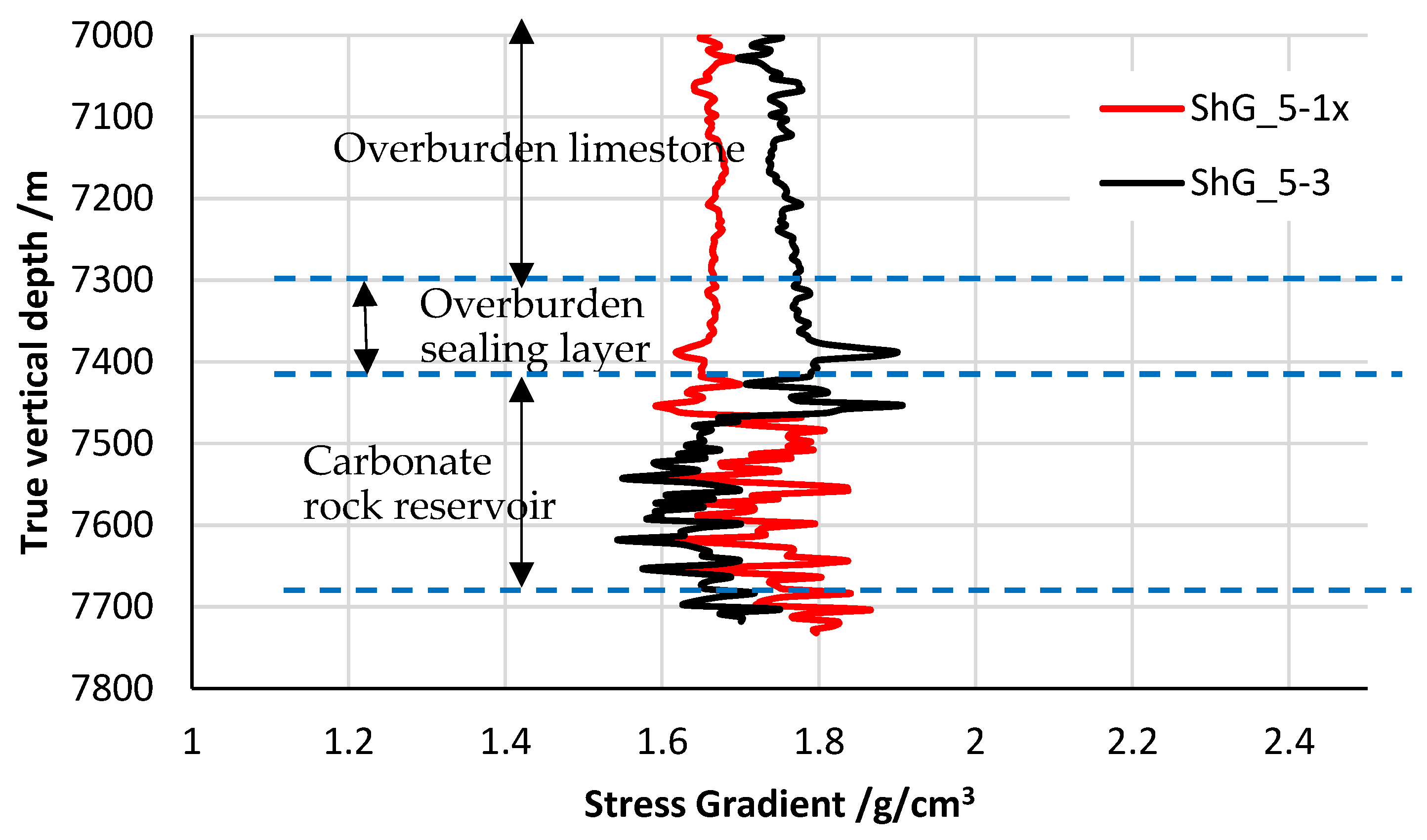
Figure 10 gives the distribution of the minimum horizontal stress gradient ShG of these two wells. The detailed procedure of analysis and data logging that is used as input to derive these two curves of the stress gradient ShG can be found in [14].
There are three layers of formations related to the depth interval shown in Figure 10: the carbonate rock reservoir, the overburden sealing layer, and the overburden limestone formation. In the overburden sealing layer, there are very few natural fractures, and its sealing function is well preserved. With an increase in depth, the magnitude of ShG at both wells maintains the same trend as that in the formation of overburden limestone. When these two wells enter the carbonate rock reservoir, it is seen that at the depth interval within the formation of the carbonate rock reservoir, the magnitude of ShG at well F8B-5-3 decreases significantly from 1.8 g/cm3 to 1.6 g/cm3. This means that the density of natural fractures has increased significantly.
On the other hand, the magnitude of ShG at well F8B-5-1x does not decrease but undergoes a stepped increase–decrease when the well exits the sealing layer and enters the carbonate rock reservoir. After this stepped increase–decrease, the curve of ShG maintains the same trend as it is in the overburden sealing layer. This indicates that the density of natural fractures at this depth interval of well F8B-5-1x is small.
Therefore, the distribution of ShG at the two wells of F8B-5-1x and F8B-5-3 indicates the distribution of the density of natural fractures in this area. Conclusions derived from Figure 10 are in good accordance with the contour of damage SDEG.

4. Conclusions

Natural fractures within carbonate rock formations were investigated by using forward modeling technology. Continuum damage mechanics and the finite element method were used to numerically model the process of fracture initiation and evolution under the loading of tectonic movement. Based on the geological analysis of natural fractures provided by the interpretation of seismic data and the numerical results of the mechanical analysis of the contour of the damage variable SDEG, the following conclusions can be obtained.
(1)
Regarding natural fractures within the Ordovician carbonate rock formation of target block F8B, they are mainly generated by tectonic movement in the Caledonian period stage 1 and stage 2. Consequently, the loading conditions of the model of geomechanics analysis includes only the tectonic movement in the Caledonian period stage 1 and stage 2, and excludes other tectonic movements.
(2)
The numerical results of the distribution of natural fractures within target formations are represented by the contour of the damage variable SDEG shown in Figure 7. It indicates that the distribution of natural fractures obtained by the forward modeling of tectonic movement is very close to the results of natural fractures obtained with the interpretation of seismic data. It also indicates that the technology developed here for the forward modeling of natural fractures is an effective tool.
(3)
The results of the natural fractures’ distribution obtained by the submodel are more accurate than those obtained with the global model. This indicates that the technology of submodeling is a necessary component of forward modeling for the purpose of minimizing computational costs and maximizing the accuracy of the numerical results of the distribution of natural fractures.
(4)
The values of parameters of tectonic movement of the Caledonian period stage 1 and stage 2 were calibrated in the process of phenomena matching for natural fractures: its orientation angle can be represented by the directional angle of the principal component of initial strain ε22, which is α = 15°, and its magnitude can be represented by ε22 = 0.024.
(5)
The numerical results of the natural fracture distribution obtained by the global model of the F8B block indicate that the maximum value of SDEG is 0.2686, i.e., the degree of fragmentation of rock within the natural fractures is 26.86%. The width of the damage localization zone, which is the width of the area of the natural fractures, is in the range of 500 m to 1000 m.
(6)
The numerical results of the contour of the damage variable SDEG show that the 3D damage mechanics model and finite element numerical analysis can better simulate the 3D spatial distribution of natural fractures caused by tectonic movement than the method of interpretation of seismic data: it not only presents conventional data of natural fractures, such as the azimuth angle and location, but also presents additional data, which include the fracture width, the degree of fragmentation of the rock, spatial penetration, and so on.
(7)
Validation of the results of the distribution of natural fractures has been performed indirectly via distribution of the minimum horizontal stress gradient ShG at two wells, F8b-5-1x and F8b-5-3.
The technology of forward modeling with damage mechanics to identify the distribution of natural fractures is particularly useful for blocks with small natural fractures/small fault displacements, which are difficult to identify by the interpretation of seismic data.

Author Contributions

Conceptualization, M.Y. and X.S.; methodology, X.S.; software, X.S.; validation, L.J.; formal analysis, J.W.; investigation, M.Y.; resources, X.S.; data curation, M.Y.; writing—original draft preparation, M.Y. and X.S.; writing—review and editing, M.Y. and X.S.; visualization, M.Y. and X.S.; supervision, X.S.; project administration, L.J.; funding acquisition, M.Y. and X.S; revising and data interpretation, Z.H.; G.S., software and data processing. All authors have read and agreed to the published version of the manuscript.

Funding

This research was funded jointly by the China National Petroleum Corporation (CNPC), grant number 2020F-46, key project “Integration and test of safe, optimal and fast drilling and completion technology for complex ultra-deep wells”, and the National Natural Science Foundation of China, grant number 11272216, Project of “Theoretical and Experimental Investigation on key mechanical problems in unconventional natural gas exploitation”.

Institutional Review Board Statement

Not applicable.

Informed Consent Statement

Not applicable.

Conflicts of Interest

The authors declare no conflict of interest.

References

  1. Deng, S.; Li, H.L.; Zhang, Z.P.; Wu, X.; Zhang, J.B. Characteristics of differential activities in major strike-slip fault zones and their control on hydrocarbon enrichment in Shunbei area and its surroundings, Tarim Basin. Oil Gas Geol. 2018, 39, 878–888. [Google Scholar]
  2. Liu, S.; Zhang, Z.; Yun, J.; Li, H.; Gao, S.; Li, J. NE-trending fault belts in Tanggubasi depression of the Tarim Basin: Features, genetic mechanism, and petroleum geological significance. Oil Gas Geol. 2018, 39, 964–975. [Google Scholar]
  3. Tian, I.; Yang, H.; Zhu, Y.; Deng, X.; Xie, Z.; Zhang, Y.; Li, S.; Cai, Q.; Zhang, Y. Geological conditions for hydrocarbon accumulation and key technologies for exploration and development in Fuman and key technologies for exploration and development in Fuman Oilfield, Tarim Basin. Acta Pet. Sin. 2021, 42, 971–985. [Google Scholar]
  4. He, D.; Zhang, L.; Wu, S.; Li, D.; Zhen, Y. Tectonic evolution stages and features of the Junggar Basin. Oil Gas Geol. 2018, 39, 845–861. [Google Scholar]
  5. Wang, W.; Yin, H.; Zhou, P. Deformation characteristics and mechanism of salt-related fold thrust belt in Tarim basin. Xinjiang Pet. Geol. 2019, 40, 68–73. [Google Scholar]
  6. Lefranc, M.; Hussein, A.M.; Tan, C.P. 3D Structural restoration and geomechanical forward modeling in a visco-plastic medium to natural fracture prediction in a Malay producing field, offshore Malaysia. In Proceedings of the The Offshore Technology Conference-Asia, Kuala-Lumpur, Malaysia, 25–28 March 2014. Paper No.: OTC-24753-MS. [Google Scholar]
  7. Noufal, A.; Sirat, M.; Steiner, S.; Trubienko, O.; Minton, J.; Zhang, X.; Herrera, A. Estimates of in situ stress and faults/fractures in carbonate reservoirs in Onshore Abu Dhabi using geomechanical forward modeling. In Proceedings of the Abu Dhabi International Petroleum Exhibition and Conference, Abu Dhabi, UAE, 9 November 2015. [Google Scholar] [CrossRef]
  8. Roberts, D.T.; Profit, M.L.; Armstrong, J.A.; Yu, J.; Crook, A.J.L. Strategies for forward modeling the evolution of geological structures undergoing large deformation. In Proceedings of the The 49th US Rock Mechanics/Geomechanics Symposium, San Francisco, CA, USA, 28 June–1 July 2015. Paper No.: ARMA 15-348. [Google Scholar]
  9. Shen, X.; Yang, L. Experiments and Theory of Damage Mechanics for Concrete, 1st ed.; Science Press: Beijing, China, 2009. [Google Scholar]
  10. Lee, J.; Fenves, G.L. Plastic-damage model for cyclic loading of concrete structures. J. Eng. Mech. 1998, 124, 892–900. [Google Scholar] [CrossRef]
  11. Liu, J.; Ding, W.; Xiao, Z.; Dai, J. Advances in comprehensive characterization and prediction of reservoir fractures. Prog. Geophys. 2019, 34, 2283–2300. (In Chinese) [Google Scholar]
  12. Qian, Y.; Sha, X.; Li, H.; Shen, X.; Xia, Y.; Liu, B.; You, D.; Wu, S.; Shi, Q. An approach to Caledonian unconformities and sequence stratigraphic pattern of Ordovician carbonate in the western Tazhong Area, Tarim Basin. Earth Sci. Front. 2013, 20, 260–274. [Google Scholar]
  13. Dassault Systèmes Simulia Corp. Abaqus User’s Manual; Volume 2: Analysis, Version 6.10; Dassault Systems: Vélizy-Villacoublay, France, 2010. [Google Scholar]
  14. Xiuping, C.; Xinpu, S.; Jingtao, L.; Guoxiao, S. Refined finite element modeling and analysis on 3D geostress field of a block in Shunbei oil field. J. Shenyang Univ. Technol. 2021, 43, 1–7. Available online: http://kns.cnki.net/kcms/detail/21.1189.T.20210315.0932.004.html (accessed on 1 October 2021).
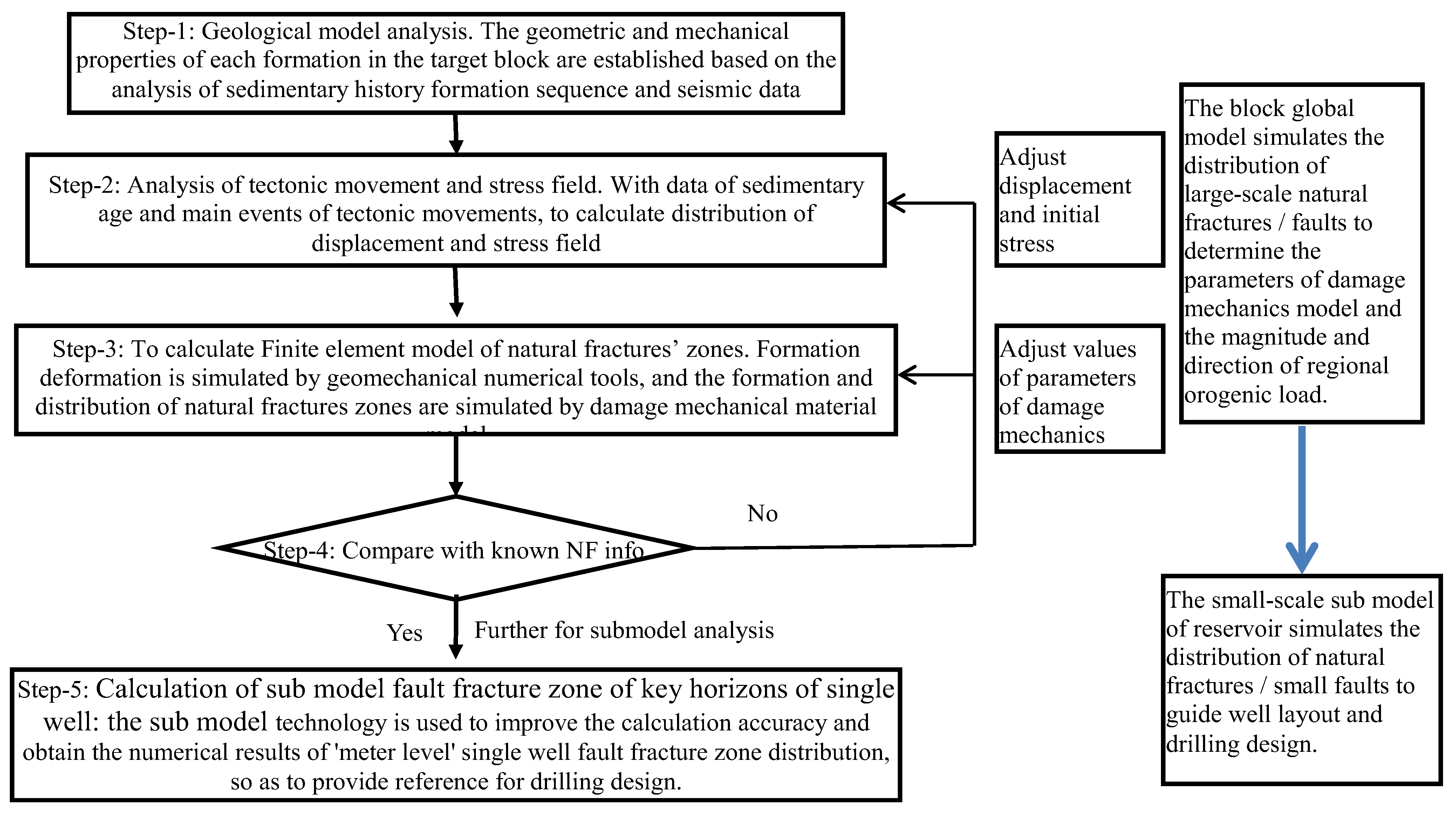
Figure 1. Flow chart of forward modeling of plastic damage calculation for natural fractures (NF) generated by tectonic movement.
Energies 15 06318 g001
Figure 2. 3D geological model of target formations at Fuman Oilfield (left) and the overlapped plane view of natural fractures (right) at each interface.
Energies 15 06318 g002
Figure 3. Plane view of distribution of natural fractures in each layer obtained from seismic data interpretation.
Energies 15 06318 g003aEnergies 15 06318 g003b
Figure 4. Plane view of natural fractures (NF) at T74 interface and illustration of classification.
Energies 15 06318 g004
Figure 5. The mesh of the finite element model.
Energies 15 06318 g005
Figure 6. Illustration of initial strain and its principal directions.
Energies 15 06318 g006
Figure 7. Plane view of contour of damage variable with α = 15° and ε22 = 0.024: (a) contour of damage SDEG at T74 interface, and (b) contour of SDEG at T76 interface.
Energies 15 06318 g007
Figure 8. Illustration of relative location of the submodel and its finite element mesh.
Energies 15 06318 g008
Figure 9. Contours of SDEG at T76 interface: (a) numerical results of submodel and (b) results of global model for the same region.
Energies 15 06318 g009
Figure 10. Distribution of minimum horizontal stress gradient ShG at locations of 2 wells.
Energies 15 06318 g010
Table 1. Values of parameters of damage evolution under compression.
Value of DcValues of εi
00
0.00340.00012
0.050.003
0.250.01
0.270.05
0.450.055
0.460.1
0.50.11
0.750.5
Table 2. Values of parameters of damage evolution under tension.
Value of DtValues of εi
00
0.15 × 10⁻⁵
0.150.00015
0.70.0005
0.750.0015
0.90.002
0.9050.5
Publisher’s Note: MDPI stays neutral with regard to jurisdictional claims in published maps and institutional affiliations.