
Automatic Determination of Rock-Breaking Target Poses for Impact Hammers


Abstract
:1. Introduction
- The design of algorithms for generating rock-breaking target poses and assessing them, which are based on the way this task is performed by human operators in mining sites. This information was obtained from good practice manuals and from interviews with operators.
- A rock segmentation procedure that is the result of merging the segmentation obtained by processing the point-cloud data and the detection of rocks obtained by image processing techniques.
- The adaptation of image processing techniques used for image segmentation (e.g., flooding or watershed) to segment point-cloud data.
- Incorporating to the end-effector’s target pose a criterion of a range of contact angles in which the hammer and the rock minimize the slippage due to impact.
2. Proposed System for Determining the Rock-Breaking Target Pose for Impact Hammers
2.1. General System Description
2.2. Rock Segmentation Subsystem
2.2.1. Sensing and Data Acquisition
2.2.2. Point Cloud Generation
2.2.3. Rock Segmentation Using Point Clouds
2.2.4. Rock Detection Using Images
2.2.5. Rock Segmentation Based on Fused Data
- If an ellipse has only one associated cluster, that cluster is considered as correctly assigned.
- If an ellipse has multiple associated clusters, only the largest cluster is considered as correctly assigned, while the others are merged to the largest.
- The remaining clusters (which have associated ellipses but were not considered as correctly assigned) are disintegrated by reassigning their points to the nearest correctly assigned clusters.
2.3. Subsystem for Generation and Evaluation of Rock Breaking Target Poses
- Generation of sub-regions.
- Validation of sub-regions.
- Generation and Hierarchization of rock breaking target poses.
2.3.1. Generation of Sub-Regions
- To evaluate whether or not a rock would pass through the grizzly, a rough estimation of its enveloping volume is made. This allows identifying the rocks that, due to their large dimensions, would not be able to easily pass through the grizzly (i.e., the rocks that the system would target during the crushing process). To estimate the rock’s enveloping volume, a 3D bounding box is constructed for each rock, using their respective point cloud. A graphic example of these bounding boxes is illustrated in Figure 8.
- The rocks that would likely pass through the grizzly (because of their low volume) are managed differently by the system, and are not considered during the rock breaking target poses’ search. For instance, there might be rocks that possess a size and shape such that, although they could pass directly through the grizzly, are stuck. These cases are often dealt with by operators by redistributing the material on the grizzly.Another possible scenario that is managed differently is when rocks that, due to lack of visibility, are wrongly classified as “small”. This case could happen, for instance, due to occlusions between rocks. These rocks are not considered for the breaking rock target pose generation, since, if they are small, they will likely fall through the grizzly after a material redistribution (performed by the hammer or due to more material being put on the grizzly) and if they are just occluded, it is likely that also because of redistributions of the material they will eventually become completely visible, and thus subject to being a target for the impact hammer.
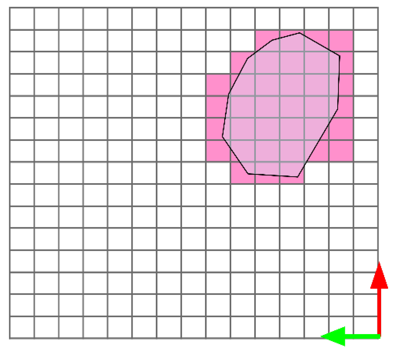
- All the rocks that would not pass through the grizzly (because of their estimated volume) are considered for the breaking rock target pose search. In these cases, the rocks’ corresponding points are grouped considering their position projected in the virtual grid cells (described previously). Thus, each of these groups of points is a sub-region associated with a particular rock. An example of these groupings is illustrated in Figure 9.
- Finally, the generated sub-regions that posses a low number of points, or whose points belong to different rocks, are discarded.
2.3.2. Validation of Sub-Regions
- Rule 1: A vertical orientation of the impact hammer’s end effector has to be maintained.
- Rule 2: The hammers’ end effector should try to break the rocks by hitting them on low curvature regions.
- Rule 3: If a rock is very large, the attempts to break it should start by trying to hit it at its “edges”.
2.3.3. Generation and Hierarchization of Rock Breaking Target Poses
- Criterion 1: Picking the most accessible pose (that is, the pose that can be reached in the shortest possible time).
- Criterion 2: Attempting to break the largest rock.
- Criterion 3: Attempting to clear a specific grizzly’s quadrant.
3. Experiments
3.1. Experimental Configuration
- For the rocks’ segmentation: Precision and recall, measured as if we were detecting rocks. The metrics typically used for segmentation tasks using images (such as the intersection over union) are not utilized, as manually labeling ground truths for the point clouds processed by the system would be highly prone to error.
- For the rocks’ instance segmentation: The number of correctly and incorrectly individualized rocks is measured.
- For the generation of rock-breaking target poses: An average score over the generated poses (limiting the generated poses to a maximum of 10), and an average score over only the highest priority pose are considered. The scores are 1 (bad), 2 (could be improved), and 3 (good), and the evaluation is performed by humans who are knowledgeable about good practices for rock-breaking mining operations. We will refer to the average score over all the generated rock-breaking poses as “Overall Rock-breaking Pose score” (ORP score) and to the average score for the highest priority pose as “Best Rock-breaking Pose score” (BRP score).
3.2. Evaluation Results
4. Discussion
4.1. Segmentation
4.2. Instance Segmentation
4.3. Rock-Breaking Pose Generation
5. Conclusions
6. Patents
Author Contributions
Funding
Institutional Review Board Statement
Informed Consent Statement
Data Availability Statement
Acknowledgments
Conflicts of Interest
References
- Salvador, C.; Mascaró, M.; Ruiz-del Solar, J. Automation of unit and auxiliary operations in block/panel caving: Challenges and opportunities. In Proceedings of the MassMin2020—The 8th International Conference on Mass Mining, Santiago, Chile, 9–11 December 2020; pp. 9–11. [Google Scholar]
- Espinoza, J.P.; Mascaró, M.; Morales, N.; Ruiz Del Solar, J. Improving productivity in block/panel caving through dynamic confinement of semi-autonomous load-haul-dump machines. Int. J. Min. Reclam. Environ. 2022, 1–22. [Google Scholar] [CrossRef]
- Correa, M.; Cárdenas, D.; Carvajal, D.; Ruiz-del Solar, J. Haptic Teleoperation of Impact Hammers in Underground Mining. Appl. Sci. 2022, 12, 1428. [Google Scholar] [CrossRef]
- Lampinen, S.; Niu, L.; Hulttinen, L.; Niemi, J.; Mattila, J. Autonomous robotic rock breaking using a real-time 3D visual perception system. J. Field Robot. 2021, 38, 980–1006. [Google Scholar] [CrossRef]
- Takahashi, H.; Sano, K. Automatic detection and breaking system for boulders by use of ccd camera and laser pointer. Fragblast 1998, 2, 397–414. [Google Scholar] [CrossRef]
- Hubert, G.; Dirdjosuwondo, S.; Plaisance, R.; Thomas, L. Tele-operation at Freeport to reduce wet muck Hazards. MassMin 2000 2000, 173–179. [Google Scholar]
- Tang, X.; Zhao, D.; Yamada, H.; Ni, T. Haptic interaction in tele-operation control system of construction robot based on virtual reality. In Proceedings of the 2009 International Conference on Mechatronics and Automation, Changchun, China, 9–12 August 2009; pp. 78–83. [Google Scholar]
- Xu, X.; Song, A.; Ni, D.; Li, H.; Xiong, P.; Zhu, C. Visual-haptic aid teleoperation based on 3-D environment modeling and updating. IEEE Trans. Ind. Electron. 2016, 63, 6419–6428. [Google Scholar] [CrossRef]
- Rusu, R.B.; Marton, Z.C.; Blodow, N.; Dolha, M.; Beetz, M. Towards 3D point cloud based object maps for household environments. Robot. Auton. Syst. 2008, 56, 927–941. [Google Scholar] [CrossRef]
- Cárdenas, D.; Mascaró, M.; Parra-Tsunekawa, I.; Ruiz-del Solar, J. Method and System for Determining and Selecting Rock Breaking Target Poses for a Rock Breaker. PCT Patent PCT/IB2021/059373, 12 October 2021. [Google Scholar]
- Mangan, A.P.; Whitaker, R.T. Partitioning 3D surface meshes using watershed segmentation. IEEE Trans. Vis. Comput. Graph. 1999, 5, 308–321. [Google Scholar] [CrossRef]
- Koschan, A. Perception-based 3D triangle mesh segmentation using fast marching watersheds. In Proceedings of the 2003 IEEE Computer Society Conference on Computer Vision and Pattern Recognition, Madison, WI, USA, 18–20 June 2003; Volume 2, pp. 27–32. [Google Scholar]
- Loncomilla, P.; Samtani, P.; del Solar, J.R. Detecting rocks in challenging mining environments using convolutional neural networks and ellipses as an alternative to bounding boxes. Expert Syst. Appl. 2022, 194, 116537. [Google Scholar] [CrossRef]
- Zhou, X.; Wang, D.; Krähenbühl, P. Objects as Points. arXiv 2019, arXiv:1904.07850. [Google Scholar]
- Hartley, R.; Zisserman, A. Multiple View Geometry in Computer Vision; Cambridge University Press: Cambridge, UK, 2003. [Google Scholar]
- Revelles, J.; Urena, C.; Lastra, M. An Efficient Parametric Algorithm for Octree Traversal. J. WSCG 2000, 8, 1–3. [Google Scholar]
- Koenig, N.; Howard, A. Design and use paradigms for gazebo, an open-source multi-robot simulator. In Proceedings of the 2004 IEEE/RSJ International Conference on Intelligent Robots and Systems (IROS) (IEEE Cat. No. 04CH37566), Sendai, Japan, 28 September–2 October 2004; Volume 3, pp. 2149–2154. [Google Scholar]
- Quigley, M.; Conley, K.; Gerkey, B.; Faust, J.; Foote, T.; Leibs, J.; Wheeler, R.; Ng, A.Y. ROS: An open-source Robot Operating System. In Proceedings of the ICRA Workshop on Open Source Software, Kobe, Japan, 12–17 May 2009; Volume 3, p. 5. [Google Scholar]


| Experimental Configuration | Description | |
|---|---|---|
| 1 rock | (i, j) | A single rock is sequentially positioned above the grizzly in a single cell (i, j), for (i, j) ∈ {(1, 1), (1, 4), (4, 1), (4, 4), (2, 2), (2, 3), (3, 2), (3, 3)}. |
| 4 rocks | corners | Four rocks that do not overlap are positioned in the corners of the grizzly, that is, in (1, 1), (1, 4), (4, 1), and (4, 4). |
| center | Four rocks that do not overlap are positioned around the center of the grizzly, that is, in (2, 2), (2, 3), (3, 2) and (3, 3). | |
| center + overlap | Four rocks are again positioned around the center of the grizzly, but this time they overlap. | |
| 5 rocks | upper/bottom row | The rocks are sequentially positioned in the upper row, lower row, leftmost |
| leftmost/rightmost column | column, and rightmost column of the grizzly. They overlap. | |
| 5 to 6 rocks + clutter | upper/bottom row | The same four settings as in the “5 rocks” case are considered (that is, overlapping rocks are sequentially positioned in the upper row, lower row, leftmost |
| leftmost/rightmost column | column, and right most column of the grizzly), however, this time small rocks cluttering the environment are present. | |
| 8 rocks | center + corners | Eight rocks are positioned in both the corners and the center of the grizzly, without overlap. |
| center + overlap | Eight rocks are positioned around the center of the grizzly, overlapping each other. | |
| 8 to 9 rocks + clutter | center + corners | The same two configurations for eight rocks are considered, that is, rocks positioned in the corners and center of the grizzly, without overlapping, and |
| center + overlap | then near the center of the grizzly, overlapping each other, however, this time small rocks are added to the environment. | |
| Experimental Configuration | Segmentation | Instance Segmentation | Rock-Breaking Pose Evaluation | ||||
|---|---|---|---|---|---|---|---|
| Precision | Recall | Correct | Incorrect | ORP Score | BRP Score | ||
| 1 rock | (1,1) | 1.0 | 1.0 | 1 | 0 | 3.00 | 3.00 |
| (1,4) | 1.0 | 1.0 | 1 | 0 | 1.67 | 1.67 | |
| (4,1) | 1.0 | 1.0 | 1 | 0 | 3.00 | 3.00 | |
| (4,4) | 1.0 | 1.0 | 1 | 0 | 3.00 | 2.67 | |
| (2,2) | 1.0 | 1.0 | 1 | 0 | 3.00 | 3.00 | |
| (2,3) | 1.0 | 1.0 | 1 | 0 | 3.00 | 2.67 | |
| (3,2) | 1.0 | 1.0 | 1 | 0 | 3.00 | 3.00 | |
| (3,3) | 1.0 | 1.0 | 1 | 0 | 3.00 | 3.00 | |
| 4 rocks | corners | 1.0 | 1.0 | 4 | 0 | 2.67 | 3.00 |
| center | 1.0 | 1.0 | 4 | 0 | 2.67 | 3.00 | |
| center + overlap 1 | 1.0 | 1.0 | 0 | 4 | 2.33 | 2.33 | |
| center + overlap 2 | 1.0 | 1.0 | 1 | 3 | 2.67 | 2.67 | |
| 5 rocks | upper row | 1.0 | 1.0 | 0 | 5 | 3.00 | 3.00 |
| bottom row | 1.0 | 1.0 | 1 | 4 | 1.67 | 1.00 | |
| leftmost column | 1.0 | 1.0 | 3 | 2 | 2.33 | 2.33 | |
| rightmost column | 1.0 | 1.0 | 3 | 2 | 2.00 | 2.33 | |
| 5 to 6 rocks + clutter | upper row | 1.0 | 1.0 | 1 | 4 | 2.33 | 2.00 |
| bottom row | 1.0 | 1.0 | 1 | 4 | 2.33 | 3.00 | |
| leftmost column | 1.0 | 1.0 | 1 | 5 | 2.67 | 3.00 | |
| rightmost column | 1.0 | 1.0 | 0 | 6 | 2.33 | 2.67 | |
| 8 rocks | center + corners 1 | 1.0 | 1.0 | 8 | 0 | 2.67 | 3.00 |
| center + corners 2 | 1.0 | 1.0 | 8 | 0 | 2.67 | 2.33 | |
| center + corners 3 | 1.0 | 1.0 | 8 | 0 | 2.67 | 3.00 | |
| center + overlap 1 | 1.0 | 1.0 | 3 | 5 | 2.33 | 3.00 | |
| center + overlap 2 | 1.0 | 1.0 | 2 | 6 | 2.33 | 3.00 | |
| center + overlap 3 | 1.0 | 1.0 | 2 | 6 | 3.00 | 3.00 | |
| 8 to 9 rocks + clutter | center + corners 1 | 1.0 | 1.0 | 5 | 4 | 3.00 | 3.00 |
| center + corners 2 | 1.0 | 1.0 | 4 | 5 | 2.33 | 3.00 | |
| center + corners 3 | 1.0 | 1.0 | 2 | 7 | 3.00 | 3.00 | |
| center + overlap 1 | 1.0 | 1.0 | 1 | 7 | 3.00 | 3.00 | |
| center + overlap 2 | 1.0 | 1.0 | 1 | 7 | 2.33 | 3.00 | |
| center + overlap 3 | 1.0 | 1.0 | 2 | 7 | 2.67 | 3.00 | |
| Experimental Configuration | Rock-Breaking Pose Evaluation | ||
|---|---|---|---|
| ORP Score | BRP Score | ||
| 1 rock | 8 trials | 2.83 | 2.75 |
| 4 rocks | 4 trials | 2.59 | 2.75 |
| 5 rocks | 4 trials | 2.25 | 2.17 |
| 5 to 6 rocks + clutter | 4 trials | 2.42 | 2.67 |
| 8 rocks | 6 trials | 2.61 | 2.89 |
| 8 to 9 rocks + clutter | 6 trials | 2.72 | 3.0 |
Publisher’s Note: MDPI stays neutral with regard to jurisdictional claims in published maps and institutional affiliations. |
© 2022 by the authors. Licensee MDPI, Basel, Switzerland. This article is an open access article distributed under the terms and conditions of the Creative Commons Attribution (CC BY) license (https://creativecommons.org/licenses/by/4.0/).
Share and Cite
Cárdenas, D.; Parra-Tsunekawa, I.; Leiva, F.; Ruiz-del-Solar, J. Automatic Determination of Rock-Breaking Target Poses for Impact Hammers. Energies 2022, 15, 6380. https://doi.org/10.3390/en15176380
Cárdenas D, Parra-Tsunekawa I, Leiva F, Ruiz-del-Solar J. Automatic Determination of Rock-Breaking Target Poses for Impact Hammers. Energies. 2022; 15(17):6380. https://doi.org/10.3390/en15176380
Chicago/Turabian StyleCárdenas, Daniel, Isao Parra-Tsunekawa, Francisco Leiva, and Javier Ruiz-del-Solar. 2022. "Automatic Determination of Rock-Breaking Target Poses for Impact Hammers" Energies 15, no. 17: 6380. https://doi.org/10.3390/en15176380
APA StyleCárdenas, D., Parra-Tsunekawa, I., Leiva, F., & Ruiz-del-Solar, J. (2022). Automatic Determination of Rock-Breaking Target Poses for Impact Hammers. Energies, 15(17), 6380. https://doi.org/10.3390/en15176380