Article

Deep Feature Based Siamese Network for Visual Object Tracking

1
Department of Computer Engineering, Sunchon National University, Suncheon 57992, Korea
2
Department of Data Science, (National) Korea Maritime and Ocean University, Busan 49112, Korea
*
Authors to whom correspondence should be addressed.
Energies 2022, 15(17), 6388; https://doi.org/10.3390/en15176388
Submission received: 19 July 2022 / Revised: 17 August 2022 / Accepted: 18 August 2022 / Published: 1 September 2022

Abstract

:
One of the most important and challenging research subjects in computer vision is visual object tracking. The information obtained from the first frame consists of limited and insufficient information to represent an object. If prior information about robust representation that can represent an object well is not sufficient, object tracking fails when not robustly responding to changes in features of the target object according to various factors, namely shape, illumination variation, and scene distortion. In this paper, a real-time single object tracking algorithm is proposed based on a Siamese network to solve this problem. For the object feature extraction, we designed a fully convolutional neural network that removes a fully connected layer and configured a convolution block consisting of a bottleneck structure that preserves the information in a previous layer. This network was designed as a Siamese network, while a regional proposal network was combined at the end of the network for object tracking. The ImageNet Large-Scale Visual Recognition Challenge 2017 dataset was used to train the network in the pre-training phase. Then, in the experimental phase, the object tracking benchmark dataset was used to quantitatively evaluate the network. The experimental results revealed that the proposed tracking algorithm produced more competitive results compared to other tracking algorithms.

1. Introduction

Visual Object Tracking (VOT) is one of the categories in computer vision and plays an important role in various tasks. VOT is widely used in video analysis application programs such as factory automation monitoring, autonomous driving, intruder monitoring, and drone tasks [1,2,3,4]. In particular, more recently, VOT analyzes a relationship between similar pixels in different frames. The information of the tracking target is initialized using the information of ground truth of the first frame in the image sequence. The output result of the tracking algorithm provides a boundary box that displays the size and location of the target for a specific frame in the image sequence [5,6,7].
However, it has a constraint of using only limited information obtained in the first frame. This constraint causes a tracker to drift in the image sequence and tracking failure to increase if prior information about robust representation that can represent an object well is not sufficient [8,9]. Despite there being studies conducted on performance improvements of VOT algorithms, many difficulties still need to be overcome. In the tracking process, situations of failing to robustly respond to changes in features of the target object occur due to various factors, namely shape, illumination variation, and scene distortion that are applied to a video sequence. This results in object tracking failure as a discrepancy between the current target and the original template takes effect [10,11].
A number of various approaches have been proposed to solve these problems in object tracking. A tracker extracts the distinctive robust feature, which is the main key feature, from the target to the extent that the target attributes can be expressed. Using this feature, an appearance is modeled to find the target from the image frame area and remove the external noise elements. To capture a change in the target shape during the tracking process, ultimately an effective feature for object tracking should be designed. Generally, attributes that change in the object’s appearance model over time should be reflected or unique features that can represent the object should be extracted.
As methods based on features, there are the correlation filter-based approach and the deep neural network approach. A tracking algorithm based on a correlation filter generates a filter through appearance modeling using the extracted object’s features. Filter weight is updated to run training from image samples of the object region that are continuously inputted while tracking progress. This training is performed in the Fourier domain using a fast Fourier transform (FFT) [12,13]. The correlation filter-based method has the advantage of fast operation speed by being computationally efficient. However, its drawback is that image information is represented inaccurately as its information is disturbed, which is caused by a boundary effect [14].
Recent study methods have focused on deep features based on deep learning, shifting from existing hand-crafted methods. A deep feature extraction method offers many advantages of being more apt to encode multi-layer information through multiple layers and being more invariant to changes in target shapes than a hand-crafted feature extraction method. Thus, it is regarded as the key element to overcome the limitation of traditional tracking algorithms. To robustly track an object using deep features, a correlation filter approach is used [15,16]. However, a correlation filter method has to continuously update an appearance model in the tracking process, because even if robust features are added, the original template model gets corrupted by the surrounding background. A deep network provides a generalization capability that captures various features by various training datasets and many parameters in a network. However, a drawback of this is that it cannot adaptively respond to appearance changes, deformation, occlusion, etc.
In this paper, unique features of the target object are extracted using a convolutional neural network (CNN) and then used in the object tracking algorithm. Using high-level features extracted in a CNN, we regard a tracking problem as a similarity comparison problem that finds a specific object within the image. Calculating image similarity entails finding feature compatibility in an image patch and comparing the features of the target object and the features of objects in the image plane. To do this, we created a customized CNN with a Siamese network, which is an architecture with a Y-shaped branch of two same CNNs. This network outputs similar feature information because the same operation is applied to the target object image and an image containing the object using the same weight. We conducted feature extraction and similarity comparison with one-shot learning through this network. A region proposal network (RPN) was used to infer a region where the target object was present from the region with the highest similarity. Using the proposed tracker, deep features of the object were extracted in real time, thereby emphasizing the distinctiveness between objects themselves or between object and background through the feature similarity comparison. Through this, we could improve the tracking algorithm’s performance. In particular, we have shown a robust performance in appearance change and distraction factors. There are three contributions to this work.
We analyze features for object tracking using CNNs trained on large image datasets to find important properties. The features of CNNs show better results than traditional tracking algorithms using hand-crafted features, helping to design effective CNN-based trackers.
We propose a method to combine two CNNs with the same structure to form a Siamese network to handle sudden appearance changes and track target objects through similarity comparison between two images.
The proposed tracking algorithm greatly mitigates object drift. We improved the tracking accuracy by introducing the anchor box concept that estimates the object area through similarity comparison between feature maps extracted from CNN. The evaluation of popular tracking benchmarks shows that the proposed method handles a variety of challenging problems well and has good tracking performance.
The present paper is organized as follows: In Section 2, studies on Siamese networks and correlation tracking are summarized, while in Section 3, a fully convolutional Siamese network is described for object tracking. Then, in Section 4, the performance comparison of experimental results between the proposed tracking algorithm and other latest tracking algorithms is presented. Lastly, in Section 5, the conclusion of this study and future research direction are presented.

2. Related Works

2.1. Correlation Filter-Based Tracking Algorithm

A correlation filter-based tracking method is a technique to train a discriminative classifier that can estimate an object’s displacement between continuous frames. Learning samples are generated using the circular correlation characteristics around the target, and a correlation filter is trained by extracting shapes from the samples. This method has achieved a very effective improvement in various challenging tasks and benchmarks owing to its high computational efficiency and kernel trick method in the Fourier domain [17]. This method consists of a form of circular shifts of input signals to a target Gaussian function, which does not need hand-crafted features of the target. Generally, a correlation filter generates a correlation peak in each interested patch of the frame and produces a low response in the background region. This is used as a reference filter to identify a specific target. Using this filter, a tracking problem can be solved, but the filter has to be trained in real time. Due to this limitation, it is not suitable for online tracking; however, the minimum output sum of squared error (MOSSE) methodology has been researched to propose a new direction [12]. Studies on various algorithms, to which the adaptive learning method theory proposed by MOSSE was applied, have been conducted. The MOSSE filter was improved by exploiting the circulant structure with kernels [18]. The channel and spatial reliability concepts were applied to the discriminative correlation filter (DCF) tracking, with the spatial reliability map being used for the filter adjustment in the partial region of the target object [19]. The improved kernelized correlation filters employed multi-channel features, and are the most widely used filters based on their overall outstanding performance and high frame-per second rate [20]. A spatially regularized discriminative correlation filter (SRDCF) tracker imposes constraints on the correlation filter coefficients according to locations, using a spatial regularization component in training to induce boundary effects [13]. An MCCTH-Staple tracker combines various types of features and configures various experts through DCF for independently tracking the target object by each expert [21].

2.2. CNN-Based Tracking Algorithm

Deep learning has been used to obtain technical features as an emerging technology and has proven its excellent capability in various works in computer vision and pattern recognition such as image and video classification as well as object recognition [22,23]. For example, a CNN has been used in various computer vision problems such as image classification, semantic segmentation, and motion recognition due to its improved performance. More recently, studies on the application of CNN’s advantages in tracking algorithms have been conducted. These tracking algorithms have combined deep feature maps with correlation filter trackers to improve tracking performance for better identification. DeepSRDCF [24] and FCNT [25] are used in object-tracking processes by extracting deep feature maps of many layers from the pre-trained model such as VGG or AlexNet. To ensure the accuracy and robustness of VOT, deep feature maps at different layers were used [26]. DeepTrack configures a number of CNN classifiers at instances of different objects to exclude noise samples during the model update, which is finely performed by adjusting a deep model online [27]. The key point that is noticeably shared by the above CNN-based trackers is as follows. First, the features produced in the last layer finely express the information represented in the object, and second, they are useful to accurately predict the object’s location even if environmental changes inside the image occur. To use features at many CNN hierarchies to the highest extent, studies on designing a dual structure have been conducted to use hierarchical features at different layers in a deep model and obtain a better shape representation from various streams.

2.3. Siamese Network

A Siamese network shows excellent performance in the problem solving of face recognition and image matching, which is the similarity comparison area [28,29]. The structure of the Siamese network is shown in Figure 1.
The research on the application of the Siamese network to object-tracking problems, which is similar to the solution of the image similarity problem, has gained traction. Much attention has been paid to a Siamese network due to its tracking accuracy and speed balance performance. The tracking problem can be defined as a problem matching the appearance of the target object with the template image in the search region. For the input data used in a Siamese network, generally, the template image of the target object and images with or without the target object are used. The target object template is normally initialized at the first frame, with the same template used in continuous frames.
The pioneering works of the Siamese network tracker are SINT and SiamFC [30,31]. These two algorithms defined the tracking problem as the measurement of the target similarities between the first and current frames. SINT defined the tracking problem as the verification work to learn the similarity between inputs. These approaches have gained many important points due to the inherent performance of Siamese networks. However, if a network is trained with a small dataset, the overfitting problem may occur. A SiamFC used an embedded CNN model to extract input image features and fused them using a correlation layer to generate a response map. Follow-up studies have been conducted to improve the SiamFC, with CFNet [32] acting as an enhanced version of SiamFC, which is a closed-form solution. A correlation filter layer is applied within the template branch to improve the information that is contained in feature maps.

3. Proposed Method

In this section, the proposed network for tracking as shown in Figure 2 is described. The proposed network employs two images as the input specified as target object and searches images. The object region coordinates them, and information about the presence of the target object are extracted as the inputs pass through the fully CNN-based backbone network and RPN. The backbone network that extracts object features was designed with a customized structure and modified into a Siamese network form. In Figure 2b, weight sharing means that each kernel of the convolution layer has the same weight. Two images input to the network pass through the same network and output a value indicating similarity. At this time, if the weights are not shared, it is structurally the same network, but it is difficult to obtain the correct result for the input data because different weights are learned. Therefore, the network is learned using the loss value output in Figure 2c, and the weights have the same value in this process.

3.1. Convolution Block for Feature Extraction

The most in-demand part of computation in a CNN is a fully connected layer, with the network proposed in this study shown as a full CNN, in which fully connected layers are removed and replaced with convolution layers. The computation amount in convolution layers increases with the number of kernels used for feature extraction. A convolution layer was designed by converting it to a bottleneck layer structure to reduce the computation amount. A bottleneck layer structure is effective in reducing the number of parameters by changing the internal structure of the network. In Equation (1), the number of parameters in the network is calculated. 
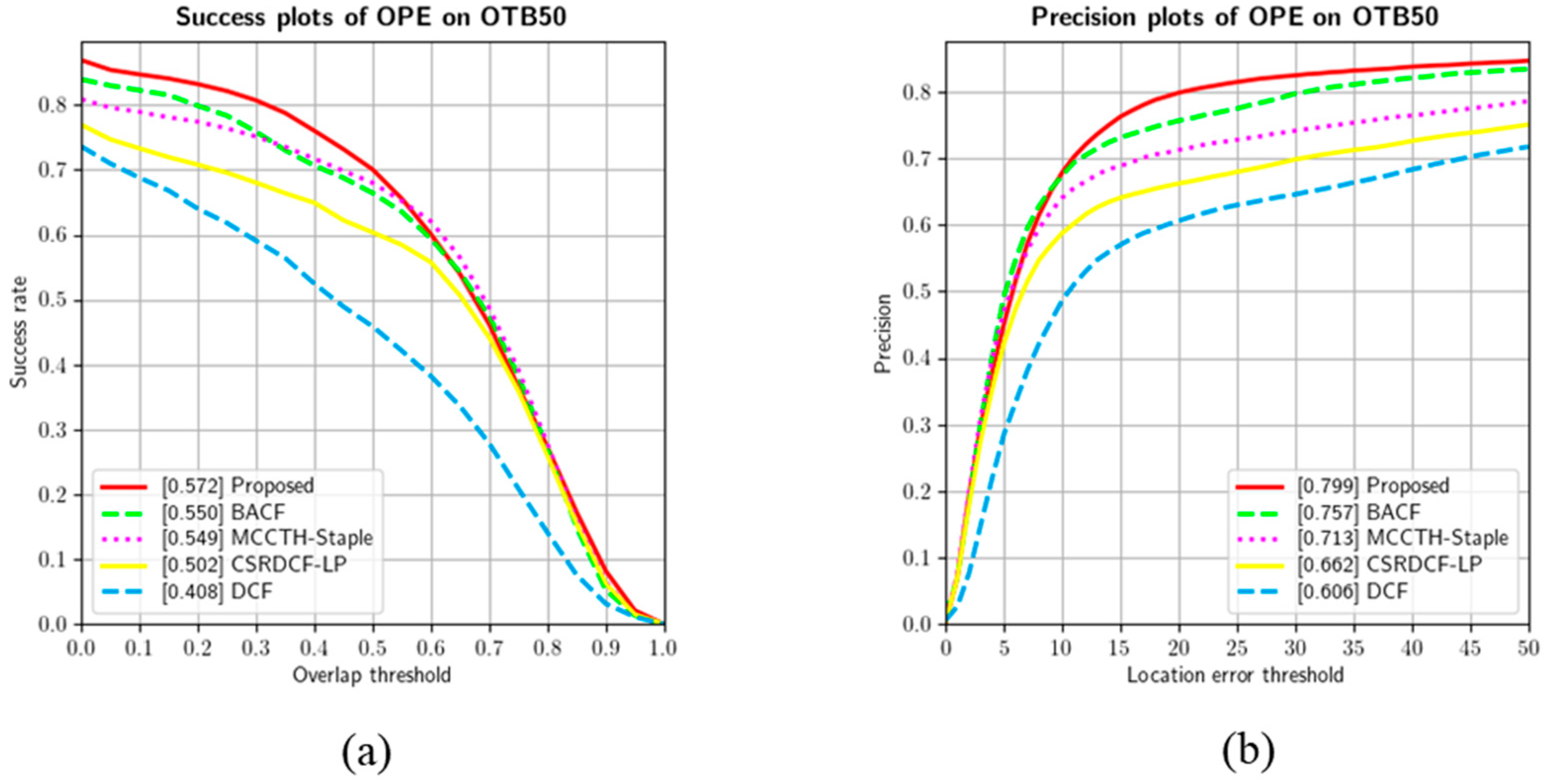
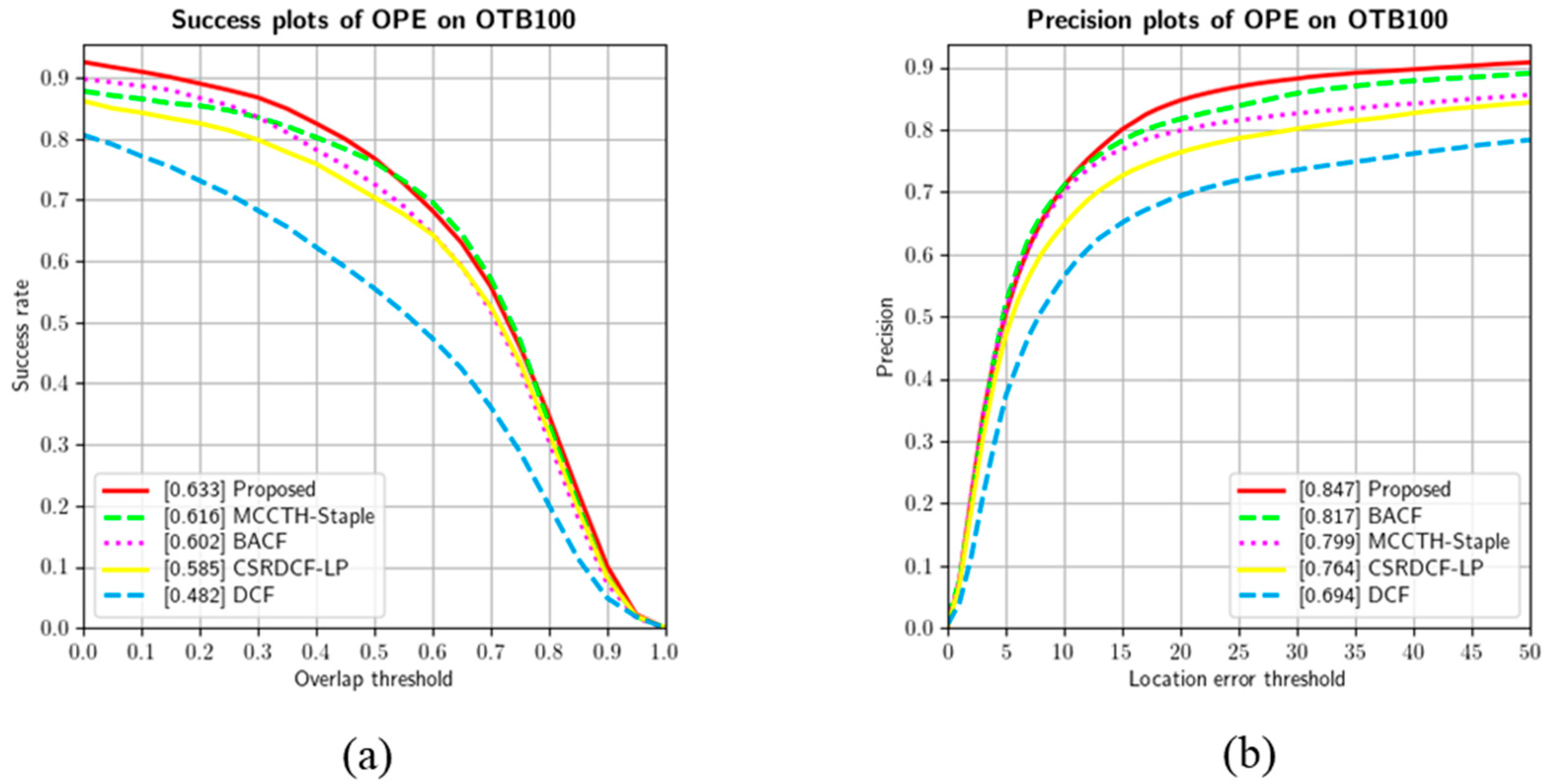
Figure 3 shows comparison of the No. of Parameters in a convolution layer.
Parameters = In   Channels × Out   Channels × Kernel   Width × Kernel   Height
The bottleneck structure consists of a three-step cycle of output compression, feature extraction using convolution, and output expansion. The output compression employs a 1 × 1 convolution. A kernel a size of 1 × 1 is used when adjusting the number of input feature maps. The output feature map in the previous layer is used as the input in the next layer. If feature maps are extracted using a smaller number of kernels than the number of input feature maps, the number of feature maps is reduced, thereby significantly decreasing the computation amount. In the feature extraction step, convolution is conducted using a kernel with a size of N × N. In the last output expansion step, the dimension is increased from a 1 × 1 to 3 × 3 convolution. Since the amount of computation and the number of parameters that are linked between layers are significantly reduced if a layer is designed with the bottleneck structure, a deeper network can be designed and learned with the same computing and time resource. Figure 4 shows the convolution block used in the proposed network, in which each block is composed of one or more bottleneck layers.
The bottlenecks were arranged reflecting the CNN’s characteristic that extracts significant features in the bottlenecks near the input layer, followed by semantic features more and more near the end. To extract more semantic features, a convolution block structure consisting of bottlenecks was iterated to increase the number of kernels, aiming to extract feature information to the highest extent. If the continuous bottleneck structure is used, it is likely for there to be a loss of information. Thus, if more than two structures are iterated, the information flow is preserved by connecting the information in the input feature map to the output feature map.

3.2. Siamese Network Architecture

A Siamese network is a neural network architecture consisting of two or more of the same networks. A Siamese network shares the same parameters and weights. The parameter update can be performed by mirroring two sub-networks. Figure 5 shows the basic structure diagram of a Siamese network. By comparing feature vectors extracted from two input images, parameters are trained to find the similarity. In a general neural network, a method to predict many classes is trained. If a new class is added or removed to/from a dataset, a problem occurs. In such a case, the neural network has to be updated and the entire dataset should be re-trained. A large amount of data is needed to train a neural network, whereas a Siamese network can train a similarity function to verify whether the appearances of two images are the same.
Figure 5 shows the network structure used to solve the tracking problem. To increase the number of kernels that extract features, a convolution block is layered in the design. The final output feature map in the tracking object region is 18 × 18 × 256 in size, while the final output feature map in the search region is 34 × 34 × 256 in size.

3.3. Region Proposal Network

The RPN is known as a very effective method for object detection. The main purpose of this network is to infer specific objects and regions that are present in the images. This network was introduced in the paper “Faster R-CNN: Towards Real-Time Object Detection with Region Proposal Networks” [33]. The region proposal is conducted by regressing the center coordinate of the anchor box in the regions where the object is likely to exist inside the image.
For the object region, a feature map that can be obtained in the last layer in the CNN is used, with Figure 6 showing the structure of the RPN. An anchor box is arranged in every cell of the feature map with a size of N × N. The number of anchor boxes used in the region proposal can be selected by a user, and the use of anchor boxes of various sizes has an advantage of inferring accurate regions. On the other hand, as the number of anchor boxes increases, so does the number of computations.
The key of the RPN is to infer a coordinate of the anchor box through regression and determine whether an object is present. An anchor box includes four values of centerX, centerY, width, and height. The number of anchor boxes used in the inference is determined according to the box scale and aspect ratio. For example, if the scale is three, and the aspect ratio is three, nine anchor boxes are created. The created anchor boxes are positioned in each cell of the feature map. CenterX and centerY are fixed for each anchor box while the width and height are determined by a ratio of the bounding box width and height of the target object.
A probability of object existence is assigned to each created anchor box. If this is zero, no object is present, while a one means that the object is present. The number of probabilities is proportional to the number of anchor boxes. Let us assume that nine anchor boxes are assigned to a feature map of 17 × 17 in size. Then, the number of coordinates to be inferred is calculated as 17 × 17 × 9 × 4 = 10,404, and the number of anchor boxes to be created as 17 × 17 × 9 = 2601. Whether the object is present is determined using the final 2601 probabilities. The final region is assigned by combining anchor boxes where the object is present. In this study, one scale and five sizes of aspect ratios were designated, and the final number of anchor boxes was five.
Figure 7 shows the proposed RPN structure. For its input, a target object feature map of 18 × 18 × 256 in size, which was extracted through the Siamese network, and a search region feature map with a size of 34 × 34 × 256, were used. These feature maps were converted into four feature maps via the convolution layer, which extracts regression and object existence probability values.
At first, feature maps for the anchor box regression values for 256 feature maps were extracted for the target object. The number of obtained output feature maps was calculated as 256 × 5 × 4 = 5120. The values for determining whether the object is present for the same feature map were extracted. Then, 256 × 5 × 2 = 2560 values could be obtained. In the search region, the same numbers of input and output feature maps were applied and computed for the coordinate regression and object existence.

4. Experiments

4.1. Experimental Environment Configuration

The hardware specifications used in the experiment are as follows: the central processing unit used was the Intel Core i7 8-generation 8700 K series, and the graphic card was the NVIDIA TITAN X Pascal 12 GB series consisting of 3840 compute-unified device architecture (CUDA) cores. The read access memory and hard disk were a DDR4 48 GB and solid-state drive, respectively, so as to guarantee fast input and output. Table 1 indicates the detailed hardware specifications used in the experiment.
The operating system was Windows 10, along with the CUDA toolkit 11.1 version and the CUDA deep neural network library 8.0 version. To implement the tracking algorithm, Python 3.8 version was used and the deep learning framework used in the network design was PyTorch 1.8 version. Table 2 indicates the detailed software specifications used in the experiment.

4.2. Dataset Configuration

In this study, the ILSVRC2017 VID dataset and object tracking benchmark (OTB) dataset were used. The datasets were divided into two parts, according to their purpose. The ILSVRC2017 VID dataset was used as the learning data to train the neural network of the proposed tracking algorithm, while the OTB dataset was employed to quantitatively evaluate the performance of the tracking algorithm [34,35].

4.2.1. ILSVRC 2017 VID Dataset

A variety of video-based datasets was proposed for various visual applications in the computer vision field. The ILSVRC 2017 VID dataset was the most represented benchmark dataset. This dataset is divided into train and validation sets consisting of 3862 video snippets and 555 video snippets, respectively. Figure 8a shows the train set in the ILSVRC VID dataset. Images extracted from each video snippet at a unit of one frame are used for training purposes. Figure 8b shows the frames extracted from each snippet video, with the number of frames being different from video to video.
The training and validation videos are extracted at a unit of frame. Each frame was matched with a 1:1 annotation, and videos can be controlled through this annotation. The key elements in the annotation are size and bndbox. The size refers to the size of the frame. Using this information, a conversion is conducted into a certain ratio size suitable for learning. “bndbox” has four attributes and refers to the location information of the object present in the frame. “xmin” and “ymin” refer to the upper left corner of the rectangular bounding box, while “xmax” and “ymax” refer to the lower right corner.

4.2.2. Object Tracking Benchmark Dataset

The OTB dataset consists of three datasets, namely OTB-2013, OTB-50, and OTB-100. OTB-2013 is composed of 50 video sequences for the quantitative evaluation of VOT algorithms. OTB-100 contains an additional 50 videos in addition to the OTB-2013 dataset, resulting in 100 videos. OTB-50 is produced by selectively extracting 50 videos whose tracking is relatively difficult out of the OTB-100 dataset.
The video sequences included in the OTB benchmark dataset include 11 types of different attributes such as illumination variation (IV), scale variation (SV), and occlusion (OCC). A video may have multiple attributes instead of a single one. Table 3 presents the detailed description of each attribute, and Figure 9 shows the video distribution graph about attributes. The count in the lower end indicates the number of videos assigned to each attribute.
Figure 10 shows the JSON file format in the OTB dataset used in the evaluation. “video_dir” refers to the dataset folder name; “init_rect” refers to the initial region coordinate; “img_names” refers to the image file name in the folder; “gt_rect” refers to the coordinate value designated in the manual; and “attr” refers to the attribute of the video.

4.3. Network Training and Testing

4.3.1. Data Preprocessing and Labeling

The ILSVRC 2017 training dataset was used to train the proposed network model. This training dataset consisted of 3862 videos and 1,122,397 images that were extracted from the videos at a unit of frame. Each frame was defined by time-series image data, and the network employed four label parameters of target image, search region, normalized bounding box coordinate, and object existence. Each data should be processed to be used as the input in the network. Two videos that were randomly chosen from each video frame in the training dataset were extracted as a pair. Since training was conducted through a comparison of similarities between objects in the network, the chronological order of the images was ignored in the data load process. Additionally, each image was used as a search region and a target image after preprocessing.
Figure 11 shows a pair of preprocessed training images. The target object is located on the left side of the images in Figure 11a,b. The preprocessing procedure of the image is as follows: for the target image, a margin of 15 to 25% in the object region area is randomly added to expand the image. The image boundary is set to the maximum margin. In the search region, the area of the object region and height are randomly reduced or expanded within a ratio of 90 to 110% of the original size.
Figure 11c,d show the final images after preprocessing. They are reconfigured so that the center point in the object region is positioned at the center of the image. The target image and search region were converted to 127 × 127 and 255 × 255 in size, respectively, for network inputs. In the size conversion, the margin was cut while maintaining the image ratio to preserve the shape of the object.
In the preprocessing procedure, the object coordinates in the original image and reconfigured image were changed. Reprocessing was conducted by reflecting the preprocessed image coordinate information in the normalized bounding box coordinate and object existence labels.
The four-dimensional score map was the final output of the network (4D) (N, 20, 17, 17). The first dimension refers to the mini arrangement size, the second dimension to the anchor box coordinate, and the third and fourth dimensions to the size of the score map.
In the labeling work, 2D, 3D, and 4D data were used. The 2D anchor box coordinate data consisted of 20 records. Each of the four coordinates of x, y, width, and height had five anchor boxes. The 3D and 4D score map size was 17 × 17 in size with 1445 anchor boxes in total. The anchor box label for regression was also made with the same size as that of the score map. The coordinate of each anchor box can be acquired by calculating the target image coordinate in the scale-adjusted search region and anchor box coordinate.
R e g r e s s i o n x = G T x a n c h o r x a n c h o r w
R e g r e s s i o n y = G T y a n c h o r y a n c h o r h
R e g r e s s i o n w = ln ( G T w a n c h o r w )
R e g r e s s i o n h = ln ( G T h a n c h o r h )
Equations (2) to (5) show the normalized anchor box coordinates to be estimated in the network [36]. Equations (2) and (3) are formulas for normalizing the center point coordinates of the anchor box, Equations (4) and (5) are formulas for normalizing the width and height of the anchor box. The normalized coordinates are used as labels, and the network is trained by applying the smooth L1 loss function to this value.
The classification label was used to determine whether the target object existed inside the anchor box. If the object did exist, a one, otherwise zero, and other than that, −1 was assigned. The object’s existence was determined according to the intersection ratio result between each anchor box and ground truth (GT) region.
The intersection over union (IOU) was used to calculate the overlap rate. If the IOU was more than 50%, it would determine that the object did exist, thereby assigning a 1 to the anchor box. If the IOU was less than 40%, it would determine that the object did not exist in the anchor box, thereby assigning a 0 to the anchor box. If the IOU was between 40% and 50%, it determined that the object’s existence was unclear. In that case, a −1 was assigned to not affect the weight training. The created number of classification labels was 1445, which is the same as the number of anchor boxes. Each label was used to train the weight in the network. To train the proposed network, the following values were used as hyper-parameters. The optimizer used Adam and set learning rate = 0.001, coefficient for primary momentum = 0.9, coefficient for secondary momentum = 0.999, and epsilon = 10 8 , weight_decay = 0.01.

4.3.2. Loss Function for Network Training

Two types of loss functions were used in the calculation for the network model, which was the key to the tracking algorithm. One was the classification loss to determine whether a tracking object was present inside the anchor box and the other was the regression loss of the anchor box coordinates to estimate the object region. The classification loss only classifies whether objects are included without specific classification of what class the anchor box is. If the object exists, 1 is assigned as positive, and 0 is assigned as negative if it does not exist. The regression loss predicts the coordinates of the anchor box. The coordinates are x and y, which are the center coordinates of the box, as well as width and height, which are the box size. The proposed network uses five anchor boxes. The classification labels obtain 2 (positive, negative) × 5 (anchor box) = 10 values, and the regression labels obtain 4 (x,y,w,h) × 5 (anchor box) = 20 values. Each value is assigned to each grid of the last feature map. Each of the loss functions was calculated using the prediction value and label in the network. To determine the object’s existence, it was assumed as a classification problem to use the cross-entropy function. Equation (6) presents the cross-entropy function.
l o s s c l s = l o g ( exp ( x [ c l a s s ] ) j exp ( x [ j ] ) ) = x [ c l a s s ] + l o g ( j exp ( x [ j ] ) )
In Equation (6), the anchor box is classified whether or not objects are included without specific classification. If the object exists, 1 is assigned as positive, and 0 is assigned as negative if it does not exist.
SmoothL1Loss was used for the regression loss of the anchor box coordinate. Equation (7) presents the SmoothL1Loss equation. In this equation, β refers to the hyperparameter, which is generally defined as one.
S m o o t h L 1 r e g = { 0.5 ( x n y n ) 2 β ,   i f   | x n y n | < β | x n y n | 0.5 × β ,   o t h e r w i s e
In Equation (7), | x n y n | value is smaller than β term, so a square term is used. Otherwise, the following L 1 r e g term is used. Due to this characteristic, it is less sensitive to abnormal values and prevents gradient exploding. The final loss function is calculated by summing Equations (6) and (7), which are expressed in Equation (8).
l o s s t o t = l o s s c l s + S m o o t h L 1 r e g

4.4. Quantitative Evaluation Index

OTB-50 and OTB-100 tracking benchmark datasets were used for performance evaluations. OTB-50 consisted of 50 videos and 29,500 frames. OTB-100 had an additional 50 videos compared to OTB-50, and included 100 videos and 50,000 frames. The videos included in the benchmark had various attributes. For the quantitative evaluation of the proposed algorithm, the one-pass evaluation (OPE) index was used.
In the OPE, two types of evaluation indices were present, namely precision and success plots. In the precision plot, the center position error was calculated. The center position was used by the reference of the GT coordinate provided in the manual. The coordinate center position produced by the tracking algorithm was calculated, and the calculated value was compared with the GT’s center position.
The success plot refers to an overlap rate of bounding boxes that surrounded the object region. To calculate an overlap rate, manual-coordinate GT and object-coordinate system truth (ST) extracted through the tracking algorithm were used. The coordinate format consisted of four values indicated by x and y coordinates, which indicated the left top, width, and height. These coordinate values were used to calculate the overlap rate of the bounding boxes.
As shown in Figure 12, GT_Box refers to a bounding box region consisting of GT coordinates, and ST_Box refers to a bounding box region of the object produced by tracking with the user’s tracking algorithm. The overlap rate is calculated by Equation (9) below.
I o U ( GT _ Box ,   ST _ Box ) = A r e a ( GT _ Box ST _ Box ) A r e a ( GT _ Box ST _ Box )
The denominator in Equation (9) is a union region of GT_Box and ST_Box in Figure 12b. The numerator is an intersection region of GT_Box and ST_Box in Figure 12a. The result of IOU is the region filled with the green-color box in Figure 12c. To express the performance rank, the area under a curve was used.

4.5. Experimental Results

In this study, the performance of the tracking algorithm was evaluated using two quantitative evaluation indicators, success plot and precision plot. The success plot measures the overlap ratio of the bounding box suggested by the algorithm and the GT box area measured by the manual method. The precision plot measures the distance difference between the center point of the bounding box presented by the algorithm and the center point of the GT box measured by the manual method. This metric indicates the accuracy with which the tracking algorithm continuously tracks the object. To quantitatively compare the performance of the proposed tracking algorithm, four tracking algorithms, namely BACF [9], CSRDCF-LP [19], DCF [20], and MCCTH-Staple [21] were used. The colors in the produced graph were red, green, magenta, yellow, and sky blue from the first to fifth ranks, respectively. The line shapes in the graph comprised a line, dash, dot, line, and dash, in that order. To ensure the statistical validity of the tracking results, the proposed algorithm and comparison algorithm were tested using the same experimental environment described in Section 4.1.
Figure 13 and Table 4 present the performance evaluation results using the OTB-50 benchmark dataset, with the proposed algorithm achieving the highest scores of 0.572 and 0.799.
Figure 14 and Table 5 present the performance evaluation results using the OTB-100 benchmark dataset. The proposed algorithm exhibited the highest scores as it achieved 0.633 and 0.847. Table 6 and Table 7 summarize all the results using the OTB dataset. The bold font was used for the highest values. Table 6 presents the results using the OTB-50 dataset. The success plot result, which showed an overlap rate with the OTB-50 dataset, achieved 0.572. This result was higher than that of the DCF algorithm, which showed the lowest result, by 0.164. It showed a slight difference (0.022) compared to BACF, which achieved the second-highest result. The precision plot achieved 0.799, which showed the center error. This result was higher than that of the DCF algorithm, which showed the lowest result, by 0.193. The BACF algorithm, which achieved the second-highest value as the same as shown in the success plot result, exhibited 0.757.
Table 7 presents the results using the OTB-100 dataset, which achieved a 0.621 in the success plot as the highest result. The algorithm that exhibited the lowest result was also the DCF algorithm, which was the same as the result of the OTB-50 dataset. The algorithm that exhibited the second-highest result with a 0.633 achieved was MCCTH-Staple, which was different from that using the OTB-50 dataset. BACF, which achieved the second-highest value using the OTB-50, showed the third-highest result with a 0.602.
The proposed algorithm achieved the highest result with a 0.847 in the precision plot. In contrast to the success plot, the BACF algorithm achieved the second-highest result with a 0.817.
The MB attribute showed high success plot results out of 11 attributes in the OTB-50 and OTB-100 datasets. Figure 15 shows the first frame in the Tiger1 video with the MB attribute, and this video contains the IV and FM attributes as well. Overall, these three attributes showed good results in the OTB-50 and OTB-100 datasets.
Figure 16 depicts the frame that includes all MB, IV, and FM attributes. Although afterimages caused by sudden object changes and blurring of pixels were found, it showed a robust tracking result even in the MB, IV, and FM attributes.
Figure 17 shows five sequences, including attributes other than MB, IV, and FM. Figure 17a–e show the sequences of Box, BlurCar4, BlurOwl, Bird2, and Coke. As shown in Figure 17, sequences a, d, and e include an occlusion attribute that hides the target object. The proposed tracking algorithm (red bounding box) exhibited good tracking without any drift that missed the object.
However, in Figure 17a, CSRDCF-LP, DCF, BACF, and MCCTH-Staple algorithms failed to track at 496 frames. In frame 455, it can be seen that the target object area is mostly obscured by obstacles. In the process of updating the object-appearance model based on the object area of this frame, it is judged that tracking failed because the appearance model was contaminated by noise (e.g., obstacle image information, background information) rather than by the target object. A similar situation can be seen in Figure 17d. In frame 63, it can be seen that all tracking algorithms localize an area other than the green GT area. In frame 95, the DCF and BACF algorithms showed the result of tracking failure, but it can be seen that the proposed algorithm tracks normally. When contamination by noise occurs in the external model, the value is continuously accumulated, so it is difficult to guarantee reliability in the comparison process. On the other hand, since the proposed algorithm is tracked through similarity comparison, re-tracking is possible when a place with high similarity between regions reappears. Figure 17b,c are images with blur caused by camera shake. In the case of Figure 17b, since the target object area is wider than in Figure 17c, it can be seen that all algorithms track relatively robustly even when blurring occurs. However, Figure 17c is more affected by the damage of the surrounding background caused by fast motion because the target object area is small. As a result, the DCF algorithm, which is highly affected by noise, failed to track. On the other hand, it shows that the proposed algorithm tracks the object well even if the object and the surrounding background are corrupted due to blurring caused by camera shake.

5. Conclusions

This study proposed a real-time single object tracking algorithm based on a Siamese network from two viewpoints of object tracking overlap accuracy and center tracking error rate. The tracking algorithm was a full CNN structure where the fully connected layers were removed to maintain spatial feature information, which was designed as a customized network. The Siamese network for feature extraction obtained the production of various feature maps using kernels 1 × 1 and 3 × 3 in size in the convolution layer. It was devised not to stop the feature flow by preventing a feature loss while the feature map produced in the bottleneck structure and input feature maps were connected and merged. The RPN estimated the object’s location through the supervised learning method and determined whether the object was present in the bounding box. Through this mechanism, the potential location of the target object could be identified in the entire image frame. The experiment showed that the proposed algorithm achieved competitive results in some video attributes compared to other tracking algorithms. However, for low resolution and scale variation attributes, the proposed algorithm still had its limitations. To solve this object-tracking problem, future research is needed to overcome this drawback. To do this, studies on performance improvements are on track to be conducted by implementing feature representation techniques as additional functions that can finely extract detailed regions rather than large appearance areas.

Author Contributions

Conceptualization, S.-C.L., J.-H.H. and J.-C.K.; Data curation, S.-C.L. and J.-C.K.; Formal analysis, S.-C.L. and J.-H.H.; Investigation, S.-C.L., J.-H.H. and J.-C.K.; Methodology, S.-C.L. and J.-C.K.; Project administration, S.-C.L., J.-H.H. and J.-C.K.; Resources, S.-C.L., J.-H.H. and J.-C.K.; Software, S.-C.L., J.-H.H. and J.-C.K.; Supervision, S.-C.L. and J.-C.K.; Validation, S.-C.L. and J.-C.K.; Visualization, S.-C.L., J.-H.H. and J.-C.K.; Writing—original draft, S.-C.L., J.-H.H. and J.-C.K.; Writing—review and editing, S.-C.L., J.-H.H. and J.-C.K. All authors have read and agreed to the published version of the manuscript.

Funding

This research was supported by Basic Science Research Program through the National Research Foundation of Korea (NRF) funded by the Ministry of Education (No. 2021R1I1A1A01044223).

Institutional Review Board Statement

Not applicable.

Informed Consent Statement

Not applicable.

Data Availability Statement

Not applicable.

Conflicts of Interest

The authors declare no conflict of interest.

References

  1. Kim, S.H.; Lim, S.C.; Kim, D.Y. Intelligent Intrusion Detection System Featuring a Virtual Fence, Active Intruder Detection, Classification, Tracking. Ann. Nucl. Energy 2018, 112, 845–855. [Google Scholar] [CrossRef]
  2. Koubâa, A.; Qureshi, B. DroneTrack: Cloud-Based Real-Time Object Tracking Using Unmanned Aerial Vehicles over the Internet. IEEE Access 2018, 6, 13810–13824. [Google Scholar] [CrossRef]
  3. Lee, S.J.; Lee, M.C. A Vision Based People Tracking and Following for Mobile Robots Using CAMSHIFT and KLT Feature Tracker. J. Korea Multimed. Soc. 2014, 17, 787–796. [Google Scholar] [CrossRef]
  4. Laurense, V.A.; Goh, J.Y.; Gerdes, J.C. Path-Tracking for Autonomous Vehicles at the Limit of Friction. In Proceedings of the American Control Conference IEEE, Seattle, WA, USA, 24–26 May 2017; pp. 5586–5591. [Google Scholar]
  5. Ma, C.; Huang, J.B.; Yang, X.; Yang, M.H. Hierarchical convolutional features for visual tracking. In Proceedings of the IEEE International Conference on Computer Vision, ICCV 2015, Santiago, Chile, 7–13 December 2015; pp. 3074–3082. [Google Scholar]
  6. Li, B.; Wu, W.; Wang, Q.; Zhang, F.; Xing, J.; Yan, J. Siamrpn++: Evolution of siamese visual tracking with very deep networks. In Proceedings of the IEEE Conference on Computer Vision and Pattern Recognition, CVPR 2019, Long Beach, CA, USA, 15–20 June 2019; pp. 4282–4291. [Google Scholar]
  7. Wang, N.; Shi, J.; Yeung, D.Y.; Jia, J. Understanding and diagnosing visual tracking systems. In Proceedings of the IEEE International Conference on Computer Vision 2019, Seoul, Korea, 27–28 October 2019; pp. 3101–3109. [Google Scholar]
  8. Du, X.; Clancy, N.; Arya, S.; Hanna, G.B.; Kelly, J.; Elson, D.S.; Stoyanov, D. Robust Surface Tracking Combining Features, Intensity and Illumination Compensation. Int. J. Comput. Assist. Radiol. Surg. 2015, 10, 1915–1926. [Google Scholar] [CrossRef] [PubMed]
  9. Kiani Galoogahi, H.; Fagg, A.; Lucey, S. Learning Background-Aware Correlation Filters for Visual Tracking. In Proceedings of the IEEE International Conference on Computer Vision, ICCV 2017, Venice, Italy, 22–29 October 2017; pp. 1135–1143. [Google Scholar]
  10. Song, Z.; Sun, J.; Yu, J. Object Tracking by a Combination of Discriminative Global and Generative Multi-Scale Local Models. Information 2017, 8, 43. [Google Scholar] [CrossRef]
  11. Li, P.; Wang, D.; Wang, L.; Lu, H. Deep visual tracking: Review and experimental comparison. Pattern Recognit. 2018, 76, 323–338. [Google Scholar] [CrossRef]
  12. Bolme, D.S.; Beveridge, J.R.; Draper, B.A.; Lui, Y.M. Visual object tracking using adaptive correlation filters. In Proceedings of the 2010 IEEE Computer Society Conference on Computer Vision and Pattern Recognition 2010, San Francisco, CA, USA, 13–18 June 2010; pp. 2544–2550. [Google Scholar]
  13. Danelljan, M.; Hager, G.; Shahbaz Khan, F.; Felsberg, M. Learning spatially regularized correlation filters for visual tracking. In Proceedings of the IEEE International Conference on Computer Vision 2015, Santiago, Chile, 7–13 December 2015; pp. 4310–4318. [Google Scholar]
  14. Kiani Galoogahi, H.; Sim, T.; Lucey, S. Correlation filters with limited boundaries. In Proceedings of the IEEE Conference on Computer Vision and Pattern Recognition 2015, Boston, MA, USA, 7–12 June 2015; pp. 4630–4638. [Google Scholar]
  15. Danelljan, M.; Robinson, A.; Khan, F.S.; Felsberg, M. Beyond correlation filters: Learning continuous convolution operators for visual tracking. In Proceedings of the European Conference on Computer Vision 2016, Munich, Germany, 8–14 September 2016; pp. 472–488. [Google Scholar]
  16. Danelljan, M.; Bhat, G.; Shahbaz Khan, F.; Felsberg, M. Eco: Efficient convolution operators for tracking. In Proceedings of the IEEE Conference on Computer Vision and Pattern Recognition 2017, Honolulu, HI, USA, 21–26 July 2017; pp. 6638–6646. [Google Scholar]
  17. Hadfield, S.J.; Lebeda, K.; Bowden, R. The visual object tracking VOT2014 challenge results. In Proceedings of the European Conference on Computer Vision (ECCV) Visual Object Tracking Challenge Workshop 2014, Zurich, Switzerland, 6–7 and 12 September 2014. [Google Scholar]
  18. Henriques, J.F.; Caseiro, R.; Martins, P.; Batista, J. Exploiting the Circulant Structure of Tracking-by-Detection with Kernels. In Proceedings of the European Conference on Computer Vision, Florence, Italy, 7–13 October 2012; Volume 7575, pp. 702–715. [Google Scholar]
  19. Lukezic, A.; Vojir, T.; Cehovin Zajc, L.; Matas, J.; Kristan, M. Discriminative correlation filter with channel and spatial reliability. In Proceedings of the IEEE Conference on Computer Vision and Pattern Recognition, CVPR 2017, Honolulu, HI, USA, 21–26 July 2017; pp. 6309–6318. [Google Scholar]
  20. Henriques, J.F.; Caseiro, R.; Martins, P.; Batista, J. High-speed tracking with kernelized correlation filters. IEEE Trans. Pattern Anal. Mach. Intell. 2015, 37, 583–596. [Google Scholar] [CrossRef] [PubMed]
  21. Wang, N.; Zhou, W.; Tian, Q.; Hong, R.; Wang, M.; Li, H. Multi-cue correlation filters for robust visual tracking. In Proceedings of the IEEE Conference on Computer Vision and Pattern Recognition 2018, Salt Lake City, UT, USA, 18–23 June 2018; pp. 4844–4853. [Google Scholar]
  22. Liu, T.; Tao, D.; Song, M.; Maybank, S.J. Algorithm-dependent generalization bounds for multi-task learning. In Proceedings of the IEEE Transactions on Pattern Analysis and Machine Intelligence 2016, Washington, WA, USA, 3 March 2016; IEEE Computer Society: Pittsburgh, PA, USA, 2016; Volume 39, pp. 227–241. [Google Scholar]
  23. Kim, J.-C.; Lim, S.-C.; Choi, J.; Huh, J.-H. Review for Examining the Oxidation Process of the Moon Using Generative Adversarial Networks: Focusing on Landscape of Moon. Electronics 2022, 11, 1303. [Google Scholar] [CrossRef]
  24. Danelljan, M.; Hager, G.; Shahbaz Khan, F.; Felsberg, M. Convolutional features for correlation filter based visual tracking. In Proceedings of the IEEE International Conference on Computer Vision Workshops, ICCV 2015, Santiago, Chile, 7–13 December 2015; pp. 58–66. [Google Scholar]
  25. Wang, L.; Ouyang, W.; Wang, X.; Lu, H. Visual tracking with fully convolutional networks. In Proceedings of the IEEE International Conference on Computer Vision, ICCV 2015, Santiago, Chile, 7–13 December 2015; pp. 3119–3127. [Google Scholar]
  26. Qi, Y.; Zhang, S.; Qin, L.; Yao, H.; Huang, Q.; Lim, J.; Yang, M.H. Hedged deep tracking. In Proceedings of the IEEE Conference on Computer Vision and Pattern Recognition 2016, Las Vegas, NV, USA, 27–30 June 2016; pp. 4303–4311. [Google Scholar]
  27. Li, H.; Li, Y.; Porikli, F. Deeptrack: Learning discriminative feature representations by convolutional neural networks for visual tracking. In Proceedings of the British Machine Vision Conference 2014, Nottingham, UK, 1–5 September 2014; Volume 1, p. 3. [Google Scholar]
  28. Brandao, P.; Mazomenos, E.; Stoyanov, D. Widening siamese architectures for stereo matching. Pattern Recognit. Lett. 2019, 120, 75–81. [Google Scholar] [CrossRef] [PubMed]
  29. Lin, T.Y.; Cui, Y.; Belongie, S.; Hays, J.; Tech, C. Learning Deep Representations for Ground-to-Aerial Geolocalization. In Proceedings of the IEEE Conference on Computer Vision and Pattern Recognition 2015, Boston, MA, USA, 7–12 June 2015; pp. 5007–5015. [Google Scholar]
  30. Tao, R.; Gavves, E.; Smeulders, A.W. Siamese Instance Search for Tracking. In Proceedings of the IEEE Conference on Computer Vision and Pattern Recognition 2016, Las Vegas, NV, USA, 27–30 June 2016; pp. 1420–1429. [Google Scholar]
  31. Bertinetto, L.; Valmadre, J.; Henriques, J.F.; Vedaldi, A.; Torr, P.H. Fully-Convolutional Siamese Networks for Object Tracking. In Proceedings of the European Conference on Computer Vision 2016, Munich, Germany, 8–14 September 2016; pp. 850–865. [Google Scholar]
  32. Xu, H.; Gao, Y.; Yu, F.; Darrell, T. End-To-End Learning of Driving Models from Large-Scale Video Datasets. In Proceedings of the IEEE Conference on Computer Vision and Pattern Recognition, ICCV 2017, Venice, Italy, 22–29 October 2017; pp. 2174–2182. [Google Scholar]
  33. Ren, S.; He, K.; Girshick, R.; Sun, J. Faster R-CNN: Towards Real-Time Object Detection with Region Proposal Networks. Adv. Neural Inf. Processing Syst. 2015, 28, 91–99. [Google Scholar] [CrossRef] [PubMed] [Green Version]
  34. Russakovsky, O.; Deng, J.; Su, H.; Krause, J.; Satheesh, S.; Ma, S.; Huang, Z.; Karpathy, A.; Khosla, A.; Bernstein, M.; et al. ImageNet Large Scale Visual Recognition Challenge. Int. J. Comput. Vis. 2015, 115, 211–252. [Google Scholar] [CrossRef] [Green Version]
  35. Wu, Y.; Lim, J.; Yang, M.-H. Online object tracking: A benchmark. In Proceedings of the IEEE Conference on Computer Vision and Pattern Recognition 2013, Portland, OR, USA, 23–28 June 2013; pp. 2411–2418. [Google Scholar]
  36. Lim, S.C. Visual Object Tracking Algorithm Using Partial Fourier Siameses Network with Fully CNN-RPN. Ph.D. Thesis, Sunchon National University, Sunchon, Korea, 2022; pp. 1–132. [Google Scholar]
Figure 1. Standard Architecture of the Siamese Network.
Energies 15 06388 g001
Figure 2. Proposed Tracking Algorithm with Siamese Network: (a) Target image and search region, (b) Siamese network consisting of convolution blocks used in feature extraction and highlighting the region of interest, (c) RPN for object region and bounding box coordinate prediction, (d) Tracking result marked by the green box.
Energies 15 06388 g002
Figure 3. Comparison of the No. of Parameters in a Convolution Layer; Above: Standard convolution, Below: Bottleneck structured convolution.
Energies 15 06388 g003
Figure 4. Structure of Convolution Block.
Energies 15 06388 g004
Figure 5. Proposed Siamese Network Architecture.
Energies 15 06388 g005
Figure 6. Anchor Box Shapes in the RPN.
Energies 15 06388 g006
Figure 7. Proposed RPN Architecture.
Energies 15 06388 g007
Figure 8. Information of ILSVRC 2017 VID Datasets: (a) Video snippets, (b) Extracted image frame of snippets.
Energies 15 06388 g008
Figure 9. Sequence Distribution Graph about Attributes.
Energies 15 06388 g009
Figure 10. Annotation Format of OTB Dataset.
Energies 15 06388 g010
Figure 11. Preprocessed Training Dataset. (a) Original target image, (b) Original search region, (c) Converted target image, (d) Converted search image.
Energies 15 06388 g011
Figure 12. Calculation Method of Intersection Ratio Using Bounding Boxes. (a) Intersection, (b) Union, (c) Applied Image, (d) Numerical Change of Overlap Rate in the Overlap Region.
Energies 15 06388 g012
Figure 13. Evaluation Graph of OTB-50 for All Attributes (a) Success Plots Graph of OTB-50, (b) Precision Plots Graph of OTB-50.
Energies 15 06388 g013
Figure 14. Evaluation Graph of OTB-100 for All Attributes (a) Success Plots Graph of OTB-100, (b) Precision Plots Graph of OTB-100.
Energies 15 06388 g014
Figure 15. MB Attribute—First Frame of Tiger 1 Sequence.
Energies 15 06388 g015
Figure 16. Frame Comprising the MB, IV, and FM Attributes.
Energies 15 06388 g016
Figure 17. Tracking Results of Various Tracking Sequences. (a) Box Tracking Result, (b) BlurCar4 Tracking Result, (c) BlurOwl Tracking Result, (d) Bird2 Tracking Result, (e) Coke Tracking Result.
Energies 15 06388 g017
Table 1. Hardware Specifications.
Detailed Specifications
CPU/RAMIntel I7-8700K 3.7 GHz/DDR4 16 G
GPUGeforce Titan Xp 12 GB 3840 CUDA cores
StorageSamsung 512 G SSD
Table 2. Software Specifications.
Detailed Specifications
OSWindows 10
LanguagePython 3.8
GPU-accelerated librariesCUDA 11.1/cuDNN 8.0
Deep Learning FrameworkPyTorch 1.8
Table 3. Sequence Attribute Table for Algorithm Evaluations.
AttributeDescription
Illumination variation (IV)Illumination variation in the target object region
Scale variation (SV)Scale variation in the tracking object
Occlusion (OCC)Occlusion generated in the target object region
Deformation (DEF)Non-rigid deformation of the object
Motion blur (MB)Motion blur occurred in the target object
Fast motion (FM)Fast motion of the object detected
In-plane rotation (IPR)Object rotation detected in the image
Out-of-plane rotation (OPR)Object rotation detected outside the image
Out-of-view (OV)A region of the object moved outside the image
Background clutters (BC)Color or texture created similar to the object
Low resolution (LR)The low resolution of the object
Table 4. Overall Performance Evaluation Results of OTB-50.
ProposedBACFMCCTH-StapleDCFCSRDCF-LP
Success0.5720.550.5490.4080.502
Precision0.7990.7570.7130.6060.662
Table 5. Overall performance evaluation results of OTB-100.
ProposedBACFMCCTH-Staple DCFCSRDCF-LP
Success0.6330.6020.6160.4820.585
Precision0.8470.8170.7990.6940.764
Table 6. Overall Performance Evaluation Results for Attributes of OTB-50 Benchmark Dataset.
ProposedBACFMCCTH-StapleDCFCSRDCF-LP
TotalSuccess0.5720.5500.5490.4080.502
Precision0.7990.7570.7130.6060.662
IPRSuccess0.5180.5400.5140.3980.462
Precision0.7410.7480.6830.5720.607
OCCSuccess0.5640.5160.5520.3890.464
Precision0.8010.7080.7150.5810.608
OVSuccess0.5480.4830.4910.3280.435
Precision0.7600.7040.6710.4430.624
IVSuccess0.5570.5870.5490.4510.466
Precision0.7660.7920.7240.6880.607
LRSuccess0.5200.4370.5710.2550.486
Precision0.8210.6950.8340.5430.711
BCSuccess0.5780.5850.5170.4370.445
Precision0.7720.7970.6790.6400.575
FMSuccess0.5690.5340.5240.4070.536
Precision0.7460.7490.6460.5670.693
MBSuccess0.5700.5420.4920.4220.535
Precision0.7670.7560.6250.5890.692
SVSuccess0.5630.5060.5250.3660.470
Precision0.7860.7100.6800.5690.622
DEFSuccess0.5360.5140.5300.4130.493
Precision0.7510.7100.6920.6120.688
OPRSuccess0.5410.5180.5360.3940.432
Precision0.7620.7190.6940.5730.562
Table 7. Overall Performance Evaluation Results for Attributes of OTB-100 Benchmark Dataset.
ProposedBACFMCCTH-StapleDCFCSRDCF-LP
TotalSuccess0.6330.6020.6160.4820.585
Precision0.8470.8170.7990.6940.764
IPRSuccess0.5580.5670.5650.4710.534
Precision0.7830.7920.7540.6780.716
OCCSuccess0.6160.5600.5950.4410.527
Precision0.8250.7560.7560.6190.671
OVSuccess0.5950.4830.4910.3280.435
Precision0.7960.7040.6710.4430.624
IVSuccess0.6420.6270.5920.4840.564
Precision0.8280.8300.7550.7270.721
LRSuccess0.5010.4460.5720.2640.495
Precision0.8290.7290.8510.5840.743
BCSuccess0.6360.6460.6100.5130.553
Precision0.8430.8630.7880.7240.715
FMSuccess0.6140.5720.5800.4640.593
Precision0.7900.7820.7130.6320.759
MBSuccess0.6280.5840.5700.4700.584
Precision0.8070.7770.7050.6140.732
SVSuccess0.5980.5380.5850.3970.537
Precision0.8080.7660.7660.6230.710
DEFSuccess0.5960.5550.5860.4500.544
Precision0.8110.7770.7790.6450.747
OPRSuccess0.5960.5180.5360.3940.432
Precision0.8160.7190.6940.5730.562
Publisher’s Note: MDPI stays neutral with regard to jurisdictional claims in published maps and institutional affiliations.

