1. Introduction
The chemical industry is responsible for about 30% of the energy used in all industrial sectors. Distillation is among the oldest operations in the process industries including the chemical industry and is widely used for separation purposes to achieve specified product purities. Besides natural gas processing, (petro)chemicals production, coal tar processing, liquefied air separation, etc. oil refining deserves special mentioning. Namely, oil refining is responsible for about 40% [
1] of the energy used in the process/chemical industry with over 40,000 columns in operation worldwide and 10–15% of the world’s energy consumption [
2].
Despite its widespread utilization distillation has clear drawbacks such as high capital (equipment) costs and large operating costs due to its low energy efficiency. In fact, the thermodynamic efficiency of distillation is rather low, ranging from 18% in air separation, to 12% in crude oil separation, and just 5% for C
2 and C
3 separation [
3].
It is well-known, that significant energy saving can be achieved if complex column configurations and heat integration are used at the expense of poorer flexibility, as well as higher capital investment and operational risks. Analysis of different distillation improvement methods was given by Kiss et al. [
1] allowing us to conclude that the most efficient methods such as heat pumps are limited only to the separation of close-boiling mixtures. In locations with cheap electricity, distillation heat pumps such as bottom flashing or vapor recompression types are profitable. In locations with expensive electricity, schemes with power recovery configurations are favored [
4].
An additional measure to increase the efficiency of distillation processes can be the power recovery of a condenser heat load by the means of an organic Rankine cycle (ORC), capable of converting waste heat into power. This could be a promising direction especially when there is currently a clear trend for industry electrification [
5] even if the efficiency of electricity generation is also quite low. A wide range of distillation columns can be integrated with the organic Rankine cycle (ORC), which is a proven method of converting low-temperature heat to electrical energy. Electricity produced by a generator coupled with an expander can be used within the process per se or in another part of the industrial site. The ORC process operates like a Rankine (or Clausius–Rankine) steam power plant using an organic working fluid instead of water. The disadvantage of such a cycle is that the efficiency does not exceed 24%.
A principle similar to ORC cycle integration to the column bottom was patented in 1984 by Carson [
6] allowing highly efficient utilization of incremental amounts of energy above what is required for the operation of a distillation column. Indeed, in distillation, the energy is consumed for vapor production at a pressure required for distillation. On the other hand, in the Rankine cycles, energy for the working fluid evaporation is required and condensation is wasted which is determined by the cycle thermodynamics. Only a smaller part of the energy generated goes into useful work which defines the cycle efficiency. Increasing the pressure in the reboiler and installing the expander downstream gives fundamentally new integrated distillation schemes that allow the separation of mixtures more efficiently from the thermodynamics viewpoint because the evaporation energy input for distillation is free of charge for the integrated process of electricity production. According to the knowledge of the authors, no publications concerning the practical implementation of the concept or the performance analysis are available in the open literature.
This paper aims to provide an informative perspective and analysis of the integration of power generation systems into the distillation process. An overview is given of the traditional methods in energy generation relevant to hydrocarbon processing. The integration schemes of gas turbines and turboexpanders are also considered. Such schemes utilize the energy of pressurized systems or the flue gases of the gas turbine can be used in the technology as such.
Based on the ideas of a turboexpander integration in distillation processes a novel approach to the reactant heating system is proposed exemplified by naphtha reforming and pyrolysis.
2. Power Supply Systems for Technological Processes
The electricity demand of the process is mainly determined by the work required for pumping, compression, air coolers, and solids-handling operations, including also the power needed for instruments, lighting, and other small users. The power is usually purchased from the local supply companies located close to the production sites [
7]. Some plants generate their own electricity to meet or exceed the plant electricity requirement, depending on whether the export of electricity is an attractive use of capital. For the industrial process of petrochemical production, a power plant is typically located near the production site and utilizes either natural gas as a primary fuel or heating oil.
As stated above 70% of power is produced from fossil fuels based on different generating options, including the Rankine cycle steam plants, gas turbine-steam, and combined cycle plants with specific advantages and drawbacks for each option.
It is worth mentioning that electrical generation efficiency is typically quite low. For example, the average efficiency of US-installed coal-based electricity generating plants is about 34% (lower heating value basis) [
8]. For typical operating parameters of 16.3 MPa and 538 °C with single or double reheat stages efficiency can reach ca. 40% and even up to 45% [
8,
9] under more severe conditions: supercritical steam conditions (245–375 bar, 565–720 °C), multiple reheating stages and low vacuum in the condenser of 3 kPa. Such an approach is mainly applicable to coal-fired power stations. Higher electricity efficiency of 60% is reached for the gas-turbine (GT) based power plants as the firing temperature approaches 1500 °C [
10]. The main fuels burned in industrial gas turbines are natural gas, petroleum distillates, residual fuel oil, propane, blast furnace gas, and butane [
11]. To enable gas turbines to operate on solid fuels like coal and biomass complex fuel gasification systems [
8,
11] such as Integrated Gasification Combined Cycle (IGCC) systems are required.
The energy costs can be reduced if the electrical power can be generated on-site and the exhaust steam from the turbines is used for process heating. The overall thermal efficiency of such systems can be in the range of 70–80%, compared with 30–60% obtained from a conventional power station, where the heat of the exhaust steam is wasted in the condenser.
Whether a combined heat and power system is worth considering for a particular site depends on the size of the site, the cost of fuel, the balance between the power and heating demands, and particularly on the availability and costs of standby supplies and the price paid for any surplus electric power generated.
Despite the relative importance of electric energy for technological processes, thermal energy consumption is much more prominent. The selection of the heat utility is determined by the process temperatures. Most plants are located on industrial sites where the heat utilities are provided by the site infrastructure. Steam is the most widely used heat source for distillation at most chemical plants. Typically, steam utility is the exhaust steam from the steam turbines of a combined heat and power system (CHP). Steam is available at 2–3 fixed pressure levels. Most industrial sites have a pipe network supplying steam at three or more pressure levels that can be 40–50 bar (high pressure), 10–20 bar (middle pressure), and 3–6 bar (low pressure) with the prices linked to the prices of natural gas or fuel oil. Fired heaters are used for process heating above 250 °C.
3. Power Systems Based on Gas Turbines and Turboexpanders
The integration of gas turbines with furnaces using the oxygen-rich hot exhaust gas as combustion air to produce power can reduce the specific energy for oil refinery or petrochemical processes, especially where the furnace is utilized for distillation. Heat can be recovered from the exhaust of a gas turbine engine and used for process heating. Selection of a gas turbine for a given application requires an accounting of various process, mechanical, operational, and cost considerations.
A principle description of a gas turbine integrated with the crude distillation unit is provided in
Figure 1. Flue gases at a temperature above 450 °C are routed to the furnace for oxidation of the fuel. Such an arrangement allows the utilization of commercial gas-fired power plants without any major modifications to the furnace. From a safety viewpoint, there should be an additional fuel stream to the furnace in case of the unexpected shutdown of the gas-fired power plant. Preliminary calculations of the authors resulted in a requirement for the specific turbine power of 127 kWe per one MW of the furnace heat capacity when the efficiency is 80%.
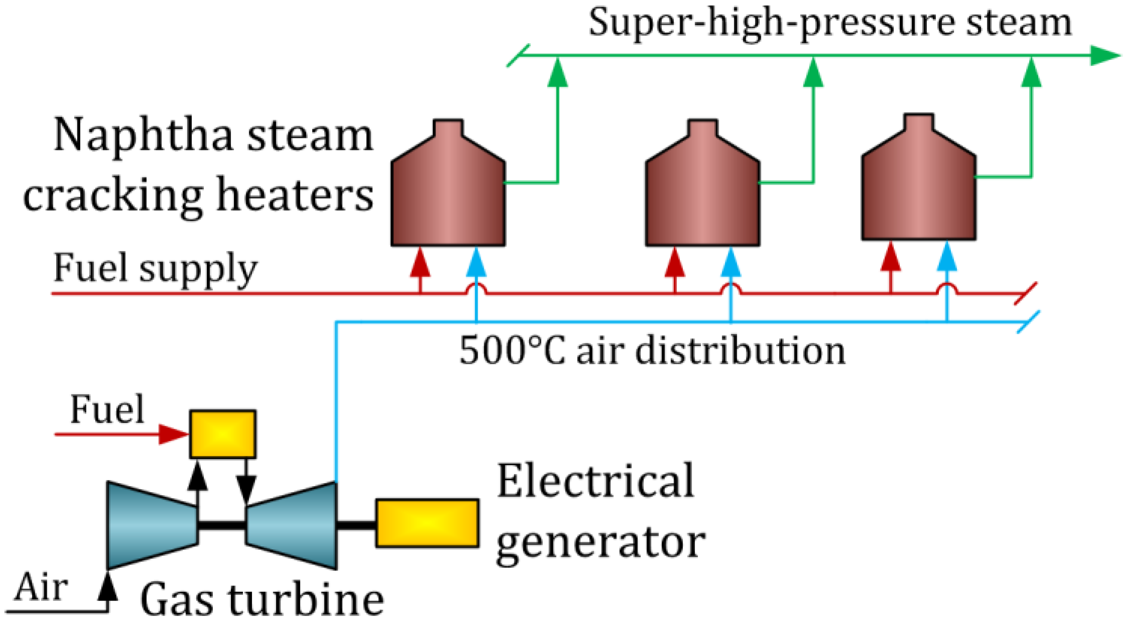
Figure 2 illustrates the integration of a gas turbine and pyrolysis furnaces for an ethylene plant [
12]. According to [
12] there are 11 plants successfully operating with such an integration concept for short residence time (SRT) pyrolysis installations being designed by ABB Lummus Global [
12]. Such arrangements are attractive for plant locations with high energy costs resulting in saving between 10 and 20 % of overall energy requirements for an ethylene plant.
The secondary firing of gas turbine exhaust would seem to be an attractive means of supplying heat to a furnace operating at an atmospheric crude oil distillation column [
13] or in a steam reforming of methane [
14].
Application of expansion turbines to recover the energy of the pressurized gaseous steams includes such processes as fluid catalytic cracking (FCC), nitric and acetic acid production as well as liquefaction of methane. In the case of distillation, the expansion turbines are commonly utilized in modern low-temperature air separation [
15] and natural gas separation units [
16] where the expansion turbines use for cooling raw gas (
Figure 3). The output of the expander helps to drive the compressor, for improved efficiency.
4. Distillation Columns Integrated with ORC
The power recovery from various heat sources utilizing the organic Rankine cycle is another application for turboexpanders. The processes in oil refining and chemical production have been identified to have the largest quantity of available waste heat for ORC applications. The ORC system potential in an oil refinery is summarized in
Table 1 [
17]. The size range is 750–5000 kW with the heat source temperature of 120–148 °C. For a refinery with a nominal capacity of 9.1 MTA (200,000 bbl/day), approximately 243.2 MW of waste heat is recoverable giving a 16 MW of electrical power generated from fluids presently cooled by air or water [
18].
ORC system efficiency could potentially be improved by 15% by using isobutane/isopentane and R227ea/R245fa as working fluids, instead of neat working fluids [
19]. Wang et al. reported the composition-adjustable ORC using a distillation column for the working fluid separation to adjust the composition of the zeotropic mixture to the required level according to the ambient temperature. Such a cycle based on the R245fa/R134a working fluid potentially can be 20–30% more efficient than the composition-adjustable Kalina cycle which is a modified Rankine cycle using ammonia/water mixture as a working fluid compared to water in the Rankine cycle [
20].
A case study reported in [
21] investigates an opportunity for the introduction of an ORC system to a Vacuum Distillation Unit (VDU) at an oil refinery plant. ORC unit was simulated using six potential working fluids, among which n-pentane demonstrated better performance than the others. The Organic Rankine cycle system in this study was supposed to operate at 20 bar pressure of n-pentane. Application of ORC for the VDU furnace exhaust cooling can increase the total installed capacity up to 3.02 MW. The system absorbs 15,660 kW of heat and produces 3.02 MWe power with an efficiency of 19%.
Another example of ORC for a crude distillation unit (CDU) is the heat recovery of a kerosene pump while cooling from 140 to 105 °C [
22]. Isobutane gave the best plant efficiency of 6.8% of the pure fluids while utilization of the butane/pentane mixture can even improve efficiency to 7.6%. It is also suggested to introduce water or heat transfer oil as an intermediate medium for ORC for better operability and safety of the waste heat recovery in a refinery [
23,
24].
In [
25] it was demonstrated that separation of the ternary azeotropic mixture of acetonitrile, ethanol, and water (ACN/EtOH/H
2O) by triple-column extractive distillation can be improved by using a four-parallel evaporator ORC system. The n-butane (R600) working fluid gave the best performance with the highest exergy efficiency while isobutane (R600a) is the most economic for column vapor condensation within the 78.3–100 °C temperature range giving 290 kW recovered power.
Figure 4 represents an illustrative example of ORC integrated with a distillation column where vapor from the column is utilized as a heat source for ORC.
An ORC system can be employed for heat integrated distillation to recover waste heat from the Vapor Recompression Column (VRC) for benzene-toluene mixture separation [
26] and BTX separation in a dividing wall column (DWC) [
4].
Table 2 gives a summary of ORC integrated with distillation and related processes. The ORC system size is varying in the range of 0.1 to 3 MW for a single or complex application adsorbing waste heat in the range of 77–380 °C. The heat of the condensing vapor is most frequently considered a heat source for ORC.
5. Integrated Power Generation for Distillation Processes
The principle, considered in the previous chapter of ORC integration into distillation allows only energy recovery and can be implemented in cases where the vapor has a relatively high temperature.
An alternative option of generating useful mechanical energy at very high efficiency by utilizing a reboiler system of a distillation column, even if patented a long time ago [
6], is somewhat forgotten deserving if not direct practical implementation but at least performance analysis. Quite similar ideas in fact have been extensively used in industrial natural gas separation for a very long time where a turboexpander is utilized to cool the process gas stream before entering a distillation column and recover power from the product streams.
The operating principle of a distillation column with a power generation cycle is illustrated in
Figure 5 for an i-pentane/n-pentane mixture as an example [
31]. The column separates a binary mixture of an equimolar composition into pure component streams with a product purity of 97.5% mass. Details of the simulations using Aspen HYSYS are described in
Appendix A.
The liquid stream from the column bottom is pressurized by a pump to a pressure of 2000 kPa. The high-pressure liquid is heated up to 163 °C and vaporized in the reboiler. The resultant high-pressure vapor stream drives the expansion turbine, which is coupled to the electricity generator or another rotating equipment. The output power of the turbine is 1972 kW, assuming an 80% isentropic efficiency. The vapor stream expands to the operating pressure of the column. The turbine exhaust vapor, superheated by 43.5 °C, enters the column bottom to supply heat for the separation process. Inside the column, the downflowing reflux liquid provides cooling and condensation of upflowing vapors. Both the working fluid condensation and mixture separation processes take place in the distillation column. Required cooling for the vapor condensation is supplied by the overhead condensing system of the column. As compared to the conventional column reboiler duty the heat duty of the vaporizer is increased by 1.86 MW due to a higher pressure and temperature in the reboiler. This value, 1.86 MW, being in the same range as reported for the ORC systems described in the previous section, corresponds to ca. 60% of the entire gas fractionation unit power consumption having a feedstock load of ~60 t/h with a C5-splitter load of 25 t/h.
At the same time, the mass flow through the vaporizer is reduced by 27.3 t/h as a result of superheated vapor entering the first tray of the column. 107 kW of the turbine output power is required for pumping the working fluid. Thus, the theoretical net output power of the cycle is 1866 kW if the mechanical efficiency of the generator is not taken into account.
There will be no negative impact on the pressure elevation due to the fact that the pressure is increased only in the reboiler heat exchanger while separation takes place at the lowest possible pressure. The heat required for distillation remains the same as in a conventional column. If the turboexpander effectively utilizes the energy of adiabatic expansion without heat losses, the power generation thermal efficiency of the distillation column integrated with the turboexpander is closer to 100% which cannot be achieved in the state-of-the-art power systems discussed in part 1 of this paper. In practice, efficiency can slightly decrease due to mechanical and generator losses.
5.1. Thermodynamic Aspects
Figure 6 illustrates the T-S diagram of the integrated i-C
5/n-C
5 distillation and power generation process. From points 1 to 2, the saturated liquid working fluid is pressurized by the feed pumps. From 2 to 3 the heat is added at a constant pressure first raising the liquid temperature to the boiling point and then evaporating it to the saturated vapor condition. From 3 to 4 the pressurized vapor is expanded adiabatically in a turbine generating mechanical energy. From 4 to 2 the vapor cools and condenses at the first tray of the column. Process 4’ to 5 and 6 to 1 are the temperature and entropy change for the upflowing vapor and the downflowing liquid correspondingly.
According to the first law of thermodynamics, this efficiency value is almost independent to the turboexpander adiabatic efficiency because the flow energy of the pressurized vapor, not converted to mechanical work, will be transformed into internal energy which is used to produce vapor for distillation.
If a turboexpander effectively utilizes the energy of the adiabatic expansion without a heat loss, the calculations show that the power generation thermal efficiency of a distillation column integrated with the expander is equal to 100% if the reboiler heat of a conventional distillation column is considered as a chargeless because this energy is necessary to implement the distillation process. It should be noted that the electrical efficiency of such a system is 12.3%, which is within the range of typical efficiencies for ORC systems. In a real case taking into account the mechanical losses in the pump and turbine shaft and the generator efficiency, as high as 95% of additional energy to the process will be converted to electricity, thus is 1.5–2.6 times more efficient than any conventional power generation technology from fossil fuel.
The results of exergy analysis of the column integrated with a turboexpander (DC-TE) for the cases of pentanes and naphtha distillation are shown in
Figure 7 which contains also a comparison with a conventional distillation column (DC), DC with an ORC system (DC-ORC) and the VRC column design. For the case of C
5 separation, it is impossible to apply DC-ORC due to the low temperature in the condenser of 50 °C. For the case of a naphtha splitter, VRC design is not applicable due to a large difference in the boiling points of the separated components, namely the temperature difference between the top and bottom is 77.9 °C.
The DC-TE scheme is applicable in both cases, which is determined only by the temperature of the heat source in the reboiler and the design aspects of the expander for the working fluid having the composition of the column bottom.
Thus, the exergy efficiency of the C5 distillation column is 2.5%, which is explained by the low temperatures of the product streams. The efficiency of the turboexpander integration scheme is 40.3% despite an increase in the reboiler exergy load due to the increase of its temperature from 63.5 to 162.7 °C. The VRC scheme, despite the reboiler duty decrease from 12.4 to 1.6 MW by operating a compressor with a capacity of 1.4 MW, is also characterized by the low efficiency of 2.6% for these particular cases.
For the case of naphtha distillation, the efficiency increases from 27.7% to 33.3%, which is close to the efficiency of the ORC integrated with DC for a partial utilization of the column vapors heat of condensation in the range from 97 to 65 °C.
Additionally, for the naphtha case, a combination of ORC and an integrated turboexpander is possible (denoted as DC-TE-ORC), allowing 42.2% efficiency and 1.05 MW of electricity.
5.2. Influence of Expander Inlet Pressure and Temperature
Similar to conventional ORC expanders the inlet pressure and temperature affect the net power generation, the expander inlet, and outlet temperature. Optimal parameters are determined by the properties of the working fluid. For a distillation column integrated with the turboexpander, the working fluid has obviously the same composition as the bottom product.
The outlet pressure of the expander is equal to the column bottom pressure, which depends on the condensation temperature of the distillate, which in turn, depends on the cooling utility temperature.
If the reflux ratio, the column top pressure, the feed flow, and composition as well as the product composition remain constant, a higher expander inlet pressure gives a higher net power output. For the example of i-pentane/n-pentane separation considered above the influence of the expander inlet pressure on the net power output is illustrated in
Figure 8. According to this Figure, for a real case of i-C
5/n-C
5 distillation, the net output power can be as high as 2.05 MW if the utility applied for distillation will allow us to operate the reboiler with the output temperature of 210 °C.
Starting from a pressure of 3000 kPa, the working fluid (n-pentane) must be superheated by 0.5 °C to avoid condensation during the expansion. An increase in the expander inlet pressure leads to a larger difference between the expander outlet temperature and n-pentane boiling temperature as shown in
Figure 8 resulting in the working fluid flow rate decrease. Such behavior is related to the need of keeping a constant heat of the expander effluent to separate a given amount (25 t/h in
Figure 6) of the i-pentane/n-pentane feed mixture.
5.3. Case Studies
Table 3 shows simulation results for the turboexpander integration of seven potential distillation columns [
31]. Selected cases involve a C
3 splitter operating at an ethylene plant, C
4 and C
5 binary mixture separation units (gas fractionation), deisopentanizer and deisohexanizer (naphtha isomerization), benzene column (aromatic production), and A naphtha splitter for crude oil distillation.
Each case determines the composition and the outlet expander pressure of the power generation cycle.
Table 3 reports the performance analysis which was carried out according to the simulation procedure defined in
Appendix A. For the selected industrial cases it is feasible to generate 0.4 to 1.8 MW of electricity despite an increase of the reboiler duty by 4.6–15% and a required temperature increase of 28–99 °C in the column reboiler.
Turboexpanders can be integrated in another way to CDU as shown for an illustrative example in
Figure 9 where a partially evaporated crude after the preheating train goes to the separator and the vapor phase proceeds to the turboexpander at an elevated pressure of 8 bar. The vapor stream comprising gases, dissolved in oil, and naphtha fractions, expands to the operating pressure of the main column. The turbine exhaust vapor may be directed to the heater or enters the column similar to a pre-flash CDU design. An estimated power generation for the large-capacity CDU of 5.5 billion tons per year can be at the level of 0.92 MW.
5.4. Technical Feasibility Aspects
Most processes operate in the context of an existing site in which a number of processes are linked to the same utility system especially, as stated above, the steam pressure is limited to a set of low, middle, and high pressure. Therefore, often at real plant sites, there are distillation columns for which the heat utility temperature exceeds what is required for a reboiler by 50–100 °C.
Figure 10 illustrates the temperature levels compared to the temperature rise in the reboiler for the integrated turboexpander. In the case of using steam of a certain quality, the pressure at the inlet of the expander and, as a result, the efficiency and the expander power will be limited by the temperature of the applied heat source. In this case, columns with a furnace are the most promising, being most often found in oil refineries.
Integration of a turboexpander into a reboiler of a distillation column with an incremental energy supply but nevertheless efficient power production is believed to be suitable for distillation of propane, normal butane, isobutane, butylenes, pentanes, amylenes, hexanes, octanes, benzene, toluene, ethylbenzene, xylene, cyclohexane and naphtha fractions. The C
3-C
5 hydrocarbon mixture can be applied as the working fluid of the ORC [
32].
Even if for these particular cases, the bottom products might not be the optimal working fluids, nevertheless they can be effectively utilized in the context of the integrated ORC being readily available. As an example, Kerme et al. proposed to use of o-xylene as a working fluid for the hybrid ORC system [
33]. It is preferred that the bottoms liquid stream is substantially free of any hydrocarbonaceous compound having a boiling point above 287 °C [
6]. The bottoms liquid stream and the working fluid also may be applied to the distillation of chemical compounds including alcohols, aldehydes, ethers, and various organic compounds including halogenated compounds or amines utilized as solvents or absorbents [
6].
An important characteristic of the integrated energy system is its robustness and minimum influence on the process, which can be safely ensured in the organic Rankine cycles. The critical piece of equipment is a turbo expander, which based on its operation principles and design, is similar to compressors, used in various process industries for compression of reactants to a certain pressure. As a failure of a compressor is critical, typically, a reserve compressor is available despite the evidently high capital costs of such an arrangement.
Contrary to compressors, a turbo expander in ORC integrated with a distillation column should not necessarily have a reserve piece if the cooling system has enough heat duty. In the case of malfunctioning, the working fluid is bypassed and condensed in ORC condensers resulting in a 10–20% increase of the duty as the energy is not withdrawn from the working fluid, thus reserve working fluid pumps should be available.
In traditional energy-generated systems which are integrated with the process industries, the capacity of energy generation can be easily increased by 1–4 MW, thus a decrease of energy generation in the case of maloperation is not critical. On the other hand, somewhat critical from the chemical technology viewpoint is the continuous cooling of the process streams. For instance, when less heat is removed from a distillation column, it can lead to a pressure increase. This will result in a reflux decrease deteriorating potentially the product quality and also diminishing the plant capacity for a unit comprising a distillation column with an ORC.
In fact, in the schemes when a turboexpander is integrated with a reboiler discussed here, robustness is less of a concern, because malfunctioning of a turboexpander will lead to a temperature increase, which can be easily compensated in distillation by controlling the flow of a utility or a fuel stream.
However, the control systems governing or tracking gas expansion on turboexpanders need to be individually adapted to process requirements to ensure safe and reliable operation under design and off-design conditions.
5.5. Economic Feasibility Study
In order to evaluate the economic feasibility of the combined distillation and power generation system the operational, capital, and total costs (TAC) were calculated and benchmarked against a conventional distillation column design. Details of the calculations are described in
Appendix B.
An important factor for the economic feasibility study is the multivariate cost of the heating utility, its temperature level, and the relation between the costs of the utility and electricity. The price charged for a utility is mainly determined by the operating cost of generating and transmitting the utility stream [
7] as was discussed in
Section 2. The temperature of the condensing vapor is usually set to the condensation temperature of the cheapest refrigerant.
The estimated economic parameters based on the natural gas and electricity world average price are summarized in
Table 4. The utility costs for the DC-TE system in comparison with conventional distillation are increased by 231,000–908,000
$/year being compensated by production of 502–1727 kW electricity with the revenue of 530,000–1,905,000
$/year. Electrical power is thus produced at a specific cost of 65.7
$/MW being very close to the cost of a heating utility (steam) of 65
$/MW. The total annualized cost (TAC) of the DC-TE system is 3.7–10.6% lower than the TAC of the conventional column.
The capital costs for the DC-TE integrated system are 28–55% larger than for DC mostly due to the high costs of turboexpanders, however, the DC-TE design has 8–10% lower capital costs than ORC and VRC designs. The most profitable design is the VRC-type heat pump; however, it can only be used in the separation of close boiling point mixtures.
6. Novel Schemes of the Integrated Power System for Reaction Processes
Based on the ideas of a turboexpander integration in distillation processes a novel approach to the reactant heating system can be proposed due to the fact that numerous chemical processes especially in the oil refining and petrochemical industry are carried out at elevated temperatures. In the case where a reactant is fed as a liquid and the reaction takes place in the gas phase, it is possible to increase the pressure and integrate a turboexpander. As in distillation, while the energy is spent on evaporation of the reactants, it can be partially recovered in the reactor effluent heat exchanger.
Figure 11 provides an illustrative example of a turboexpander integrated with the naphtha reforming process which is one of the main methods for obtaining aromatic hydrocarbons and high-octane gasoline components. The figure contains also the operation parameters together with the estimated energy values, calculated in Aspen HYSYS. A continuous catalyst regeneration type of reforming was selected because it operates at a lower pressure than more common semi-regenerative types [
34].
For the naphtha reforming process, the turboexpander operation can only be organized upstream by mixing the feedstock with hydrogen, since the hydrogen pressure is increased by the compressor leading to inefficient operation from the thermodynamics viewpoint.
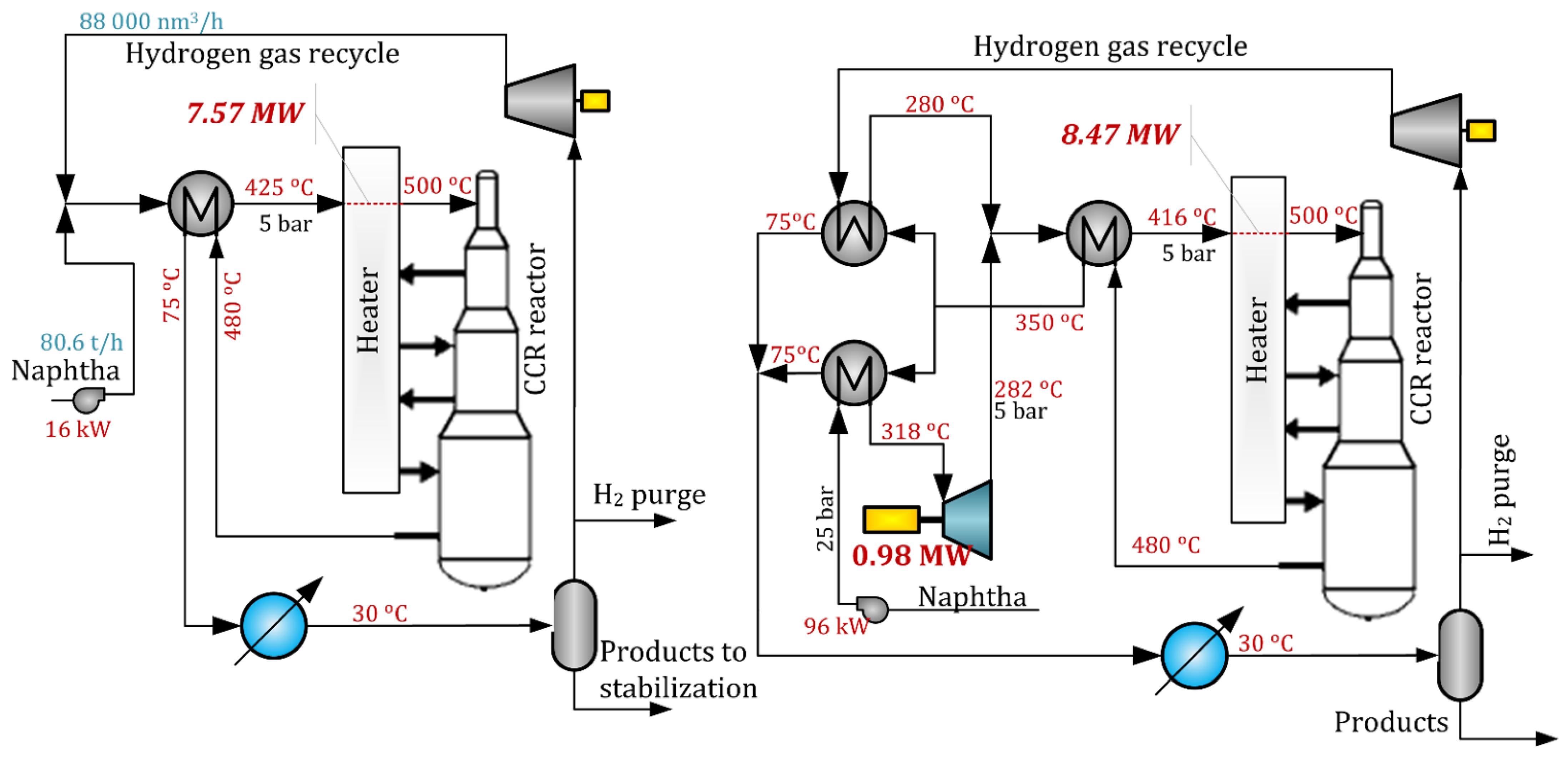
In the scheme under consideration, which has an arbitrarily chosen capacity of 80.6 t/h (644,800 tons per year), the naphtha is preheated and evaporated in a separate heat exchanger to a temperature of 318 °C for complete evaporation of the feedstock at a pressure of 25 bar. It is preferred to install a separator upstream of the turboexpander (not shown in
Figure 10) to withdraw a potentially existing liquid. In the turboexpander, the expansion of the pressurized naphtha vapors occurs with 0.98 MW of power generation. Subsequently, the naphtha stream is mixed with hydrogen followed by heating in the reactor effluent heat exchanger using the reactor effluent stream. The final heating to the reaction temperature of 500 °C provided by a furnace. Theoretically, the described scheme will not affect the reforming process per se, not influencing the temperature in the reactors. The energy requirements for the integrated process requires are compensated by an increase in the furnace duty from 7.57 up to 8.47 MW with the pump duty also increasing from 16 up to 96 kW. The additional energy input of 0.98 MW is completely converted to electricity if the pressure decrease and mechanical losses are not taken into account in this illustrative simulation example.
Another example of an efficient integrated reaction section design might be naphtha pyrolysis which is the main process of monomers production.
Figure 12 shows a general concept of the turboexpander integration into a typical thermal cracking section of the olefin plant based on THE flowsheet described in [
35]. A typical feature of this process is the high temperature of the reaction and a specific way of cooling the products, as the latter is not involved in the heat exchange with the feedstock but is rather utilized for high-pressure steam generation. The feedstock heating and evaporating in the steam presence is done by the flue gases in the convection chamber of the pyrolysis furnace. In the turboexpander integration design, by analogy with the previous scheme, the mixing of the feedstock with supplementary streams occurs after expansion from a high-pressure level of the feedstock in the turboexpander. The pressure of the turbine exhaust stream should be sufficient enough to pass the last heating section and the reaction radiant tubes.
In real conditions for the two considered examples a complex optimization of the pressure level, heating equipment design and pressure loss considerations will be required.
7. Conclusions
In the overview, various integrated systems were considered with a focus on distillation processes in the oil refining and petrochemical industry.
It was pointed out that despite extensive research conducted over a long time in the field of electricity generation from fossil fuels, the efficiency of such systems is quite low (36–60%) requiring harsh working fluid conditions and complex designs of the power systems.
In oil refining and petrochemical processes, integrated electricity generation schemes based on gas turbine and power recovery turbine integration received limited application mainly determined by the feature of the process.
The ORC system has great potential to be implemented in the distillation processes in oil refining and chemical production. The ORC system size can vary in the range of 0.1 to 3 MW for a single or complex application adsorbing waste heat in the range of 77–380 °C. The heat of the condensing vapor is most frequently considered a heat source for ORC.
Another option for generating useful mechanical energy at very high efficiency is the integration of a turboexpander to the reboiler system of a distillation column which was thoroughly analyzed in this paper for the first time. The analyzed examples are still close to the industrial ones being, however, devoid of technical nuances related to their utilization on particular production sites. The results of analysis using Aspen HYSYS of seven distillation columns integrated with a turboexpander showed a possibility to generate 0.4 to 1.8 MW of electricity despite an increase of the reboiler duty by 4.6–15% and a required temperature increase of 28–99 °C in the column reboiler. It should be noted that in all the cases the additional heat duty is converted to electricity at a very high efficiency up to 100% if mechanical losses and generator efficiency are not taken into account which cannot be achieved in the state-of-the-art power systems discussed in part 1 of this paper.
The exergy efficiency of DC-TE schemes can achieve the level of 33.3–40.3% which is relatively high for distillation processes and is close to the efficiency of the ORC integrated with DC.
The TAC of distillation can be increased by ca. 5–15% with the specific costs of additional generated electricity being very close to the costs of a heating utility. DC-TE scheme has lower economic indicators than the integration of ORC or VRC designs due to the required increase of the column duty. The capital costs for the DC-TE integrated system are 28–55% larger than for DC, however, the DC-TE design has 8–10% lower capital costs than ORC and VRC designs.
However, integration of a turboexpander to distillation can be applied more widely as it is not limited to the temperature difference of separated components or the temperature levels of column vapors. In fact, it is determined only by the temperature of the heat source in the reboiler and the design aspects of the expander for the working fluid having the composition of the column bottom.
Based on the ideas of a turboexpander integration in distillation processes a novel approach to the reactant heating system can be proposed which was illustrated for naphtha reforming and naphtha pyrolysis as examples.
Despite the requirement of additional heat duty, the integrated turboexpander can be a very efficient method of power generation from fossil fuels considered for oil refining and the petrochemical industry. It can be considered for the systems where ORC or heat-pumps designs are not implemented or can be combined with ORC to increase the capacity of a power system.


