Article

Impact of Radial Air-Gap Eccentricity on Stator End Winding Vibration Characteristics in DFIG

1
Hebei Key Laboratory of Electric Machinery Health Maintenance and Failure Prevention, North China Electric Power University, Baoding 071003, China
2
Power Electronics, Machines and Control Group, University of Nottingham, Nottingham NG7 2RD, UK
3
State Grid Hebei Electric Power Company, Shijiazhuang 050022, China
*
Author to whom correspondence should be addressed.
Energies 2022, 15(17), 6426; https://doi.org/10.3390/en15176426
Submission received: 18 August 2022 / Revised: 25 August 2022 / Accepted: 31 August 2022 / Published: 2 September 2022
(This article belongs to the Section F3: Power Electronics)

Abstract

:
In this paper, qualitative theoretical derivations, finite element analysis (FEA) and experiments are used to investigate the electromagnetic force (EF) and vibration characteristics of end windings. In contrast to previous studies, this study focuses not only on end winding EF/vibration under normal and radial static air gap eccentricity (RSAGE) conditions, but also for the cases of radial dynamic air gap eccentricity (RDAGE) and radial dynamic static hybrid air gap eccentricity (RHAGE). Firstly, the magnetic flux density (MFD) is derived for normal and radial air gap eccentricity (RAGE) faults, and detailed EF expressions are obtained before and after the RAGE fault. The finite element analysis (FEA) and experimental studies were performed on a four-pole DFIG at a speed of 1500 rpm to verify the proposed theoretical analysis. It is shown that RSAGE only enlarges the EF/end winding vibration and does not introduce new frequency components. RDAGE not only increases EF/end winding vibration but also introduces new frequency components. RHAGE can be seen as a superimposed effect of RSAGE and RDAGE.

1. Introduction

According to the “Global Wind Report 2022”, the global new wind power capacity was 93.6 GW in 2021. The cumulative wind power installed capacity reached 837 GW, an increase of 12.4% from the previous year. Large-capacity wind power generation units are the future development trend, and DFIG is currently the mainstream model of land wind power. The stator winding is the key component of the generator [1], and the stator winding insulation is one of the most vulnerable parts of the generator [2]. In addition to normal aging factors, the vibration wear of the winding is an important factor that damages the stator winding of the generator [3,4]. In fact, the windings are constantly vibrating due to the electromagnetic forces (EF) acting on the stator windings during the normal operation of the generator. [5]. With the increase in generator capacity, the EF will also increase [6], and the insulation layer of the winding will be more severely tested. The stator end winding is a fault-prone part due to its complex structure and special position [7].
A large number of scholars have studied the vibration and insulation wear of generator windings. As early as 1931, J.F. Calvert researched the forces in turbine generator stator windings [8]. In 1996, J.A. Tegopoulos set out from the density of magnetic flux to calculate and analyze the EF of turbine generator winding [9,10]. Ranran Lin analyzed the end winding vibration caused by the steady-state magnetic force in the induction machine [11]. R. Albanese proposed a novel numerical approach to calculate the time evolution of the three-dimensional distribution of the EF in the end winding regions of large-turbine generators [12]. Alireza Ghaempanah studied the influence of rotor winding and stator stepped-end iron core on the EF distribution of the turbine generator stator end winding by means of simulation [13]. D. Lin proposed a new analytical method that considers both fringing and leakage fluxes in the winding end region to compute the end-winding leakage inductance [14]. Katsutoku Takeuchi optimized the 2D finite element calculation model to achieve the accuracy of the 3D model to calculate the end magnetic field in a shorter time [15]. P.G.S. Kumar studied the vibration characteristics of stator end windings [16]. Jiang H-C et al. comprehensively analyzed the transient EF of the turbine generator stator winding [17] and studied the EF and mechanical response of the stator winding before and after the rotor inter-turn short-circuit fault [18].
More notably, most generators run in a sub-health state. The occurrence of faults such as the eccentricity of the generator will increase the mechanical stress [6] and thermal stress [19] of the winding, which will aggravate the damage of the winding insulation. The air gap eccentricity fault is a common mechanical fault of generators [20] which is usually divided into static air gap eccentricity (RSAGE), radial dynamic air gap eccentricity (RDAGE) and radial dynamic static hybrid air gap eccentricity (RHAGE) [21].
Scholars have conducted extensive research on magnetic field characteristics [22,23,24], current characteristics [25,26], electromagnetic torque [27] and vibration characteristics [28,29,30,31,32] under air gap eccentricity faults. The air gap eccentricity fault of the generator will distort the air gap magnetic field which will affect the current fluctuation and aggravate the vibration of the stator, rotor and winding. S.T. Wan analyzed the vibration characteristics of the stator and rotor caused by a RHAGE fault in the turbogenerator [28]. J. Zhang diagnosed the rotor eccentricity faults of a high-voltage motor by analyzing vibration signals [29]. Zaixin Song studied eccentricities and the resulting vibration characteristics of an interior permanent magnet synchronous generator, and introduced the method of eccentricity detection by vibration characteristics [30]. Y.-L. He et al. considered the effect of short-circuit location on stator end winding vibration in relation to static air gap eccentricity [6].
Regrettably, research on the vibration of DFIG has mainly focused on the vibration characteristics of the stator [31] and rotor [32], ignoring the winding vibration characteristics. In fact, studying the vibration characteristics of stator winding under the air gap eccentricity fault is of great value for detecting air gap eccentricity and preventing winding from winding vibration wear.
This article explores the vibration characteristics of stator windings before and after DFIG eccentricity. The rest of this paper is organized as follows. Section 2 presents the detailed theoretical analysis procedure, while Section 3 validates the proposed model by both finite element calculation and experimental test on a four-pole DFIG. Finally, the main conclusions are drawn up in Section 4.

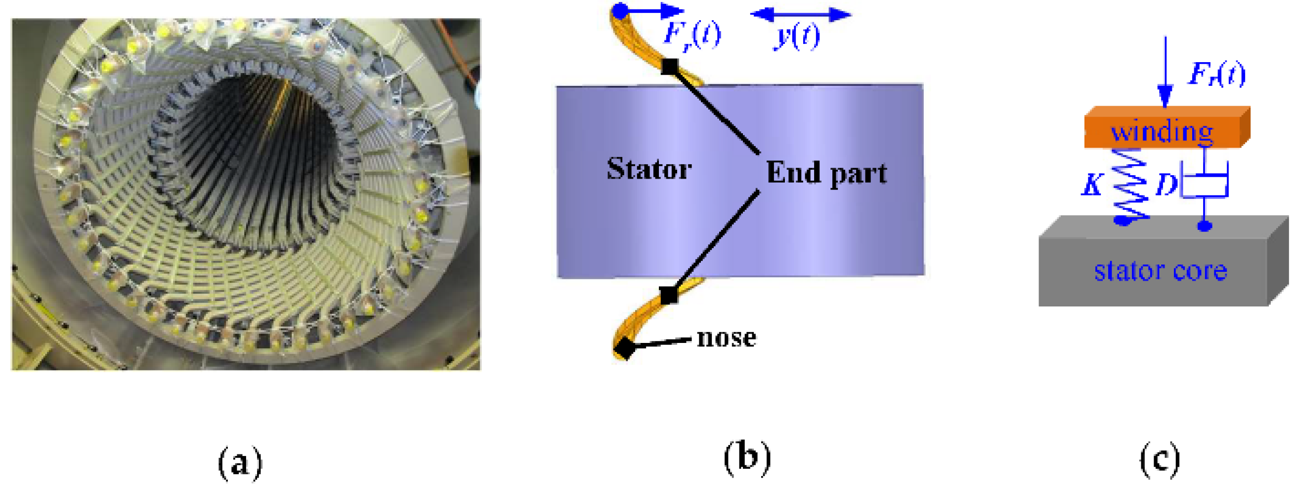
2. Theoretical Analysis

Effect of RAGE on MFD

The magnetic flux density (MFD) of DFIG is the product of magnetomotive force (MMF) and permeance per unit area (PPUA), which can be expressed as
B α m , t = f α m , t Λ α m , t
where B is MFD, f is MMF, and Λ is PPUA.
The MMF can be written as
f ( α m , t ) = f p ( α m , t ) + v f v ( α m , t ) + μ f μ ( α m , t ) = F 0 cos ( p α m ω 1 t φ p ) + v F v cos ( v α m ω 1 t φ v ) + μ F μ cos ( μ α m ω μ t φ μ )
where
v = ± k 1 Z 1 + p , k 1 = 1 , 2 μ = ± k 2 Z 2 + p , k 2 = 1 , 2 ω μ = ω 1 1 + k 2 Z 2 1 s / p
where fp (αm, t), fv (αm, t), and fμ (αm, t) are, respectively, the main wave synthetic MMF, the stator harmonic MMF, and the rotor harmonic MMF. F0, Fv, and Fμ are the main wave synthetic MMF amplitude, stator harmonic MMF amplitude, and rotor harmonic MMF amplitude, respectively. φp is the initial angle of the main wave synthetic MMF, φv and φμ are the initial angles of the stator v and rotor μ sub-harmonic MMF. In addition, p is the number of pole pairs, μ is the polar logarithm of the tooth harmonic magnetic potential of the rotor winding, and v is the polar logarithm of the tooth harmonic magnetic potential of the rotor winding. Z1 is the number of stator slots; Z2 is the number of rotor slots; s is the doubly fed induction generator sliding rate; ωμ is the angular frequency of the μ-order harmonic magnetic potential of the rotor relative to the stator; and ω1 is the angular frequency of the synthesized magnetic potential of the main wave.
The size of the air gap PPUA is closely related to the air gap length, which can be affected by eccentric failure. The schematic diagrams of RSAGE and RDAGE are shown in Figure 1, and the air gap length expressions under normal and eccentric conditions are as follows:
g a m , t = g 0 normal g 0 ( 1 δ s cos α m ) RSAGE g 0 [ 1 δ d cos ( ω r t α m ) ] RDAGE g 0 [ 1 δ s cos α m δ d cos ( ω r t α m ) ] RHAGE
where t is time; αm is the position angle of the air gap along the circumferential direction; g is the length of the radial air gap that changes with t and αm; g0 is the uniform air gap length under normal conditions; ωr is the rotational angular frequency of the rotor; and δs and δd are the value of static eccentricity and dynamic eccentricity, respectively.
PPUA can be obtained as
Λ a m , t = μ 0 g a m , t Λ 0 + k 1 λ k 1 + k 2 λ k 2 + k 1 k 2 λ k 1 λ k 2 · · · · · · · · · · · · · · · · · · · · · · · · · · · · · · · · · · · normal ( Λ 0 + k 1 λ k 1 + k 2 λ k 2 + k 1 k 2 λ k 1 λ k 2 ) ( 1 + δ s cos α m + δ s 2 cos 2 α m ) · · · · · · RSAGE ( Λ 0 + k 1 λ k 1 + k 2 λ k 2 + k 1 k 2 λ k 1 λ k 2 ) [ 1 + δ d cos ( ω r t α m ) ] · · · · · · · · · · · · RDAGE ( Λ 0 + k 1 λ k 1 + k 2 λ k 2 + k 1 k 2 λ k 1 λ k 2 ) [ 1 + δ s cos α m + δ d cos ( ω r t α m ) ] · RHAGE
where Λ0 is the unchanged part of the air gap magnetic permeability; λk1 is the harmonic magnetic permeability that occurs when the surface of rotor is smooth and the stator is slotted; λk2 is the harmonic magnetic permeability that occurs when the surface of stator is smooth and the rotor is slotted; and λk1λk2 is the harmonic magnetic permeability caused by the interaction when the stator and the rotor are simultaneously slotted.
Feeding (2) and (5) into (1), MFD can be written as:
B α m , t = f α m , t Λ α m , t = F 0 Λ 0 cos p α m ω 1 t φ p + v F v Λ 0 cos v α m ω 1 t φ v + μ F μ Λ 0 cos μ α m ω μ t φ μ + k 1 F 0 Λ 0 λ k 1 2 cos v α m ω 1 t φ v + k 2 F 0 Λ 0 λ k 2 2 cos μ α m ω μ t φ μ normal
Due to limited space, only the air gap MFD expression under normal conditions is listed here, and the detailed equations can be seen in Appendix A.
As indicated in Equation (6), the frequency components of the air gap magnetic density will not be changed by the occurrence of the radial static air gap eccentricity fault. However, the frequency component related to fr (where f = 2πω) will be increased due to the occurrence of a radial dynamic air gap eccentricity fault. According to the above discussion of the correspondence between the PPUA and air gap length, after the occurrence of the radial static air gap eccentric fault, the frequency component of the air gap magnetic density increases when the air gap length decreases. In addition, the air gap length changes with time after RDAGE occurs, so the main frequency components (fu/f1) of MFD will not change significantly. However, the amplitude of the frequency components related to fr will add significantly with the deepening of the fault degree. Furthermore, the influence of radial dynamic static hybrid air gap eccentricity on the air gap magnetic density frequency components can be regarded as the superposition of radial dynamic air gap eccentricity and radial static air gap eccentricity.
The diagram of the stator core and winding are shown in Figure 2. In fact, the straight parts of the stator windings are exposed to more EF (the MFD is larger here). However, the straight part is fixed by the stator core, so the vibration of this part is generally not considered. The end part of the stator windings extend beyond the stator core and are less structurally rigid than the straight part. The end winding structure can be regarded as a beam structure fixed at both ends, which is susceptible to vibration caused by the excitation of the winding EF. Due to torsion in the position of the structure, the nose end is more susceptible to deformation and wear under the action of vibration and stress. The system differential equation corresponding to the stator end winding is:
[ m ] y ( t ) + [ D ] y ( t ) + [ K ] { y ( t ) } = f ( t ) y ( t ) = a y
where [m] is the mass matrix of the stator core mass point; [D] is the damping matrix in radial direction; [K] is the stiffness matrix in radial direction; y(t) is the displacement of the unit mass point; y’(t) is the speed; y”(t) is the acceleration; and f(t) is the excitation force of the system, that is, the winding EF. Here, the displacement response matrix is periodic and can be treated as the mathematical description of the mechanical vibration. According to the same frequency correspondence relation between the exciting force and the movement, the vibration should have the same frequency/harmonic components as the radial electromagnetic force. In practice, forces are very difficult to measure due to measurement conditions. Alternatively, one tests acceleration, which is a common parameter representing vibration (and the method used in this paper), because the force is proportional to the acceleration of the end winding.
The EF expression for the stator end winding can be calculated by processing the air-gap MFD for normal and RAGE faults. The calculation process and results are as follows:
F r = η B α m , t I L 1 = B e n d α m , t I L 1 = B e n d 2 α m , t L 1 2 v / Z = L 1 2 v Λ 0 2 2 Z { F 0 2 [ 1 + cos 2 p α m ω 1 t φ p ] + 2 v F 0 F v cos [ ( p ± v ) α m ( ω 1 ± ω 1 ) t ( φ p ± φ v ) ] + 2 μ F 0 F μ cos [ ( p ± μ ) α m ( ω 1 ± ω μ ) t ( φ p ± φ μ ) ] + v 1 v 2 F v 1 F v 2 cos [ ( v 1 ± v 2 ) α m ( ω 1 ± ω 1 ) t ( φ v 1 ± φ v 2 ) ] + 2 μ v F μ F v cos [ ( μ ± v ) α m ( ω μ ± ω 1 ) t ( φ μ ± φ v ) ] + μ 1 μ 2 F μ 1 F μ 2 cos [ ( μ 1 ± μ 2 ) α m ( ω μ 1 ± ω μ 2 ) t ( φ μ 1 ± φ μ 2 ) ] } · · · · · · · · · · · normal
where v is the line velocity of the magnetic field cutting the winding; Z is the reactance of the winding; and L1 is the length of the stator winding perpendicular to the direction of the magnetic field. In order to save text space, only the EF formulas under normal circumstances are listed here, and the detailed equations are shown in Appendix B. The MFD and EF frequency components under normal and RAGE faults are summarized, as shown in Table 1.
As shown in Equation (8) and Table 1, the frequency components of the winding EF are only fu1 ± fμ2, f1 ± fμ, f1 ± f1, 2f1 and fu1 ± fμ2 in the normal state, and the frequency components will not change after the RASGE fault. However, the appearance of RDAGE and RHAGE will bring new frequency components of fu1 ± (fu2 ± fr), f1 ± (fu ± fr), f1 ± (f1 ± fr).
In addition, the EF of the stator end winding at the minimum air gap increases after the occurrence of RSAGE. Additionally, the amplitude of each frequency component will expand as the fault increases. The appearance of RDAGE will make the air gap length of DFIG change continuously, so the EF experienced by each winding also changes accordingly. With the increase in the fault degree, the amplitude of each frequency component in the EF will become larger, and the frequency components related to the rotation speed fu1 ± (fu2 ± fr), f1 ± (fu ± fr), f1 ± (f1 ± fr) will add more obviously. It is worth noting that, in this paper, RHAGE denotes the accumulation of RDAGE and RSAGE to the identical degree (RHAGE(0.1) = RDAGE(0.1) + RSAGE(0.1)), where the frequency components are consistent with RDAGE and the amplitude increases with the degree of eccentricity.

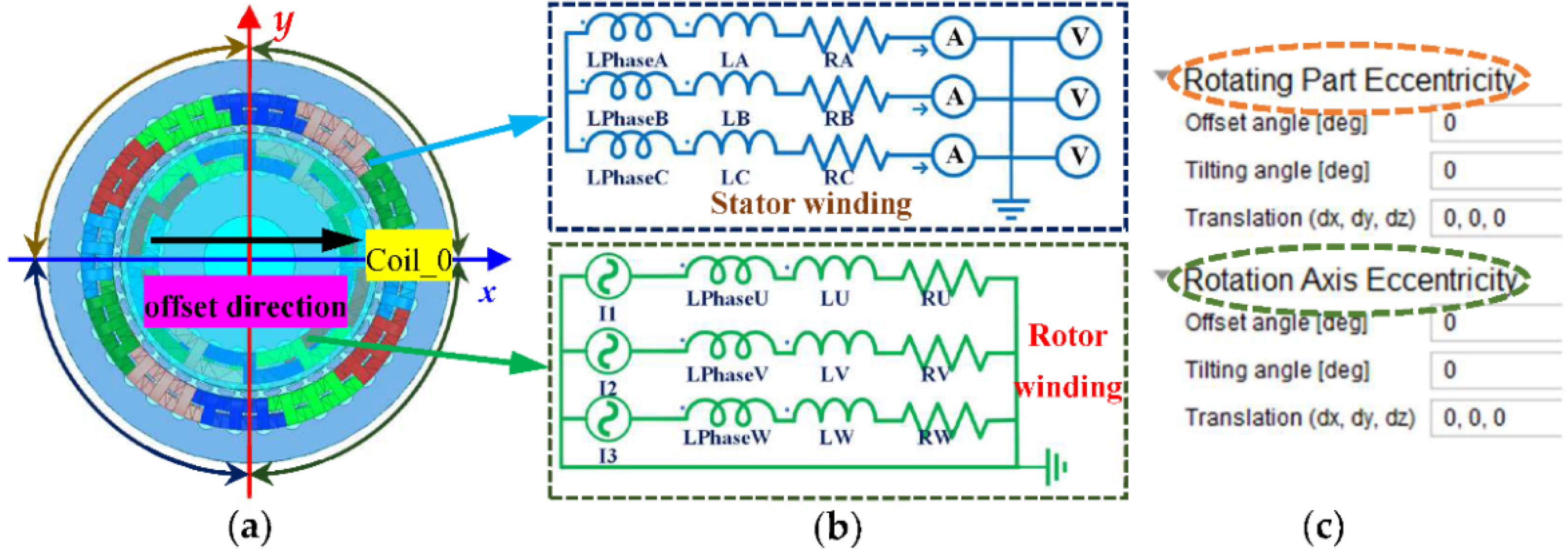
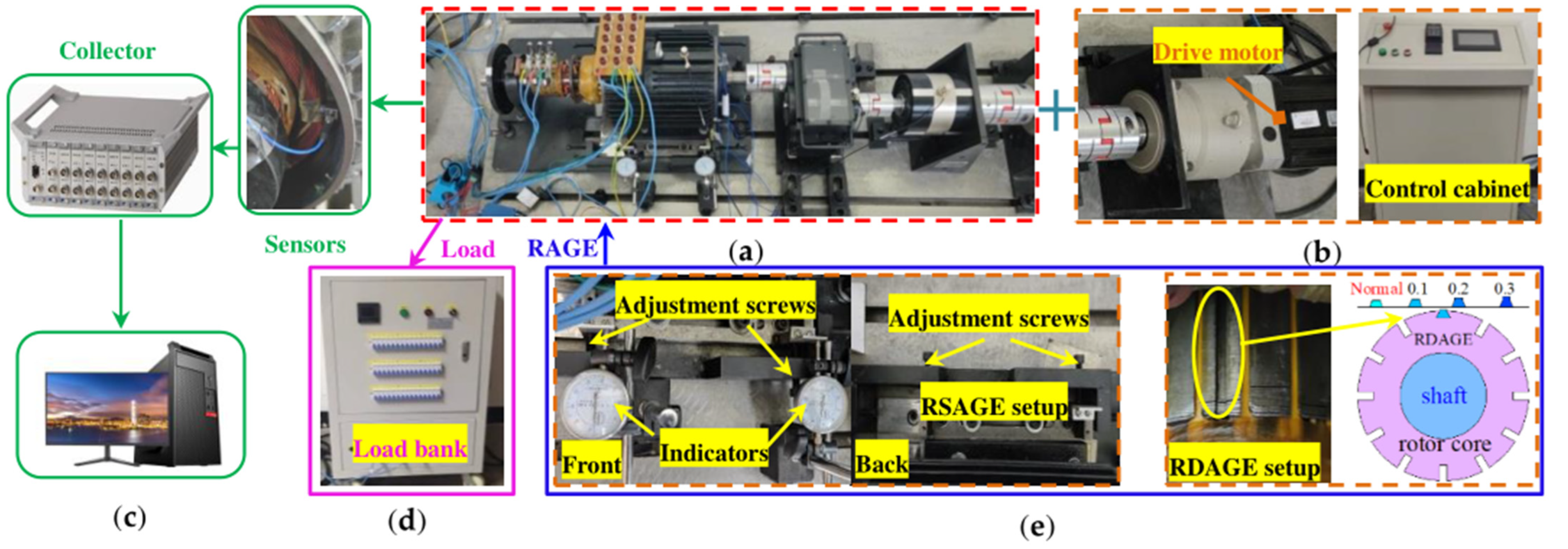
3. FEA and Experiment Study

3.1. FEA and Experiment Setup

The simulation and experiments in this paper are based on a 5.5 kW DFIG experimental unit, as shown in Figure 3 and Figure 4, and the main parameters of DFIG are shown in Table 2.
In order to comprehensively analyze the EF of the stator winding, this paper uses Ansys Electronics 18.2 to establish a Maxwell 3D simulation model, as seen in Figure 3a. The external circuit of the model is shown in Figure 3b. The generation of the RAGE fault models is implemented by the “Maxwell Eccentricity” module in “ACT Extensions”, as shown in Figure 3c. To be specific, by changing the parameters behind both the “rotating part” and the “rotating axis” to simulate the RSAGE fault, the RDAGE fault only changes the “rotating part”. The RHAGE is the combined state of RSAGE and RDAGE, i.e., RHAGE(0.1) = RDAGE(0.1) + RSAGE(0.1). The number after RAGE is the amount of eccentricity in millimeters. Since the eccentricity direction is in the positive direction of the x axis, the stator winding corresponding to the minimum air gap position in RSAGE is Coil_0.
Since the rotor is fixed to the base through the bearing housing, the eccentric setting in this paper is achieved by moving the stator and windings. The experimental unit is shown in Figure 4a, and the drive motor and control cabinet are shown in Figure 4b. The radial displacement of the stator can be achieved by adjusting the two screws on the front side and another two screws on the back side, as shown in Figure 4e, whilst the specific radial offset is measured by the dial indicators. Additionally, RDAGE is simulated by slotting the rotor, and the experimenters adjusted the degree of RDAGE by controlling the size of the wedges embedded in the eccentric groove. Specifically, the higher the wedges embedded in the eccentric groove are, the greater the degree of RDAGE eccentricity is. The PCB accelerometer is installed in the radial direction on the stator winding to test the radial vibration, as indicated in Figure 4c. The external equipment of the generator (load bank) is shown in Figure 4d. The specific parameters of the experimental fault settings are consistent with the simulation.

3.2. Results and Discussion

In this paper, the actual speed of the simulation model is consistent with that of the experimental device, which is 1460 rpm. The sliding rate can be calculated by substituting the actual velocity into “s = (1500 − 1460)/1500 = 2.7%”. Only the case where k2 is ±1 was selected for analysis. Through further calculation, the value of fμ can be obtained as 535/635. Due to space limitations, in this paper, the position (as shown in Figure 1) at minimum air gap are used for MFD analysis and the corresponding winding positions is Coil_0. The changes in the amplitude and frequency components of the MFD corresponding to this point before and after RAGE are shown in Figure 5.
According to Figure 5a,d, the MFD and its frequency components at the minimum air gap will increase after RSAGE. After RDAGE, the minimum air gap position in an RSAGE fault may be at its minimum or maximum in an RDAGE fault as the minimum air gap position is in constant change. Therefore, the MFD amplitude at this point is constantly changing under an RDAGE fault, as shown in Figure 5b. However, the amplitude of each frequency component increases as the degree of the fault increases, as indicated in Figure 5e. For RHAGE, the magnitude of the MFD will increase overall, but some moments are consistent with the normal situation, as shown in Figure 5c. In addition, all eigenfrequency components will increase after RHAGE, as can be seen in Figure 5f.
As the three phase windings are symmetrically distributed in the stator slot, the electromagnetic forces of phases A, B, and C windings have similar variations. In the interest of space, this paper only takes the A-phase winding as an example to illustrate the electromagnetic force variation characteristics. The simulation results of the Coil_0 end winding (the smallest air gap position) EF before and after SAGE fault are shown in Figure 6.
The stator end winding EF under normal and RAGE conditions are shown in Figure 6. According to Figure 6a,c,e, it can be seen that the stator end winding EF increases after the RAGE fault occurs. As shown in Table 1 and Table 3 and Figure 6, under normal conditions, the frequency components of EF are fμ1 ± fμ2(0/100), f1 ± fμ(485/585/685), f1 ± f1(0/100), and 2f1(100). In the case of RSAGE, the frequency components of stator EF will not alter, as shown in Figure 6b, but the frequency amplitude will increase with the extent of the fault. However, the new frequency components of fμ1 ± (fμ2 ± fr) (25/75/125), f1 ± (fμ ± fr) (460/560/510/610/660/710) and f1 ± (f1 ± fr) (25/75/125) are added after the RDAGE fault, as shown in Figure 6d. RHAGE will have the same frequency components as RDAGE, as illustrated in Figure 6f. In general, the more severe the RAGE, the greater of the winding EF.
The time and frequency domains of the stator end winding vibrations obtained by experiment are as shown in Figure 7. As shown in Figure 7a,c,e, the experimental data are complex (the data are interwoven and not easily distinguishable) due to the number of external influences on the generator during the experiment. Therefore, the root mean square values in the time domain are derived. It can be seen that the presence of RAGE will increase the stator end winding vibration, which will intensify with the increase in eccentricity. Furthermore, the vibration frequency components of the end winding are consistent with the EF of stator winding. Specifically, as shown in Figure 7b, there is no alteration in the frequency components of the winding vibration after the RSAGE fault, however, the amplitude of each vibration frequency component increases. However, the RDAGE fault not only introduced new frequency components such as: fμ1 ± (fμ2 ± fr) (25/75/125), f1 ± (fμ ± fr) (460/560/510/610/660/710), and f1 ± (f1 ± fr) (25/75/125), but also caused the amplitude of each frequency component to increase with the magnitude of the fault, as shown in Figure 7d. From Figure 7f, it can be seen that, in the RHAGE case, the vibration frequency components of the stator end winding include both the frequency components under the RSAGE and RHAGE faults, and increase with the degree of the fault.

4. Conclusions

In this paper, the vibration characteristics of the stator end windings of DFIG before and after RSAGE, RDAGE, and RHAGE faults were studied. The detailed expressions for the stator end windings EF before and after eccentric faults were derived. The results of the FEA and experiments verified the correctness of the theoretical part. Several important conclusions were obtained, as follows:
(1)
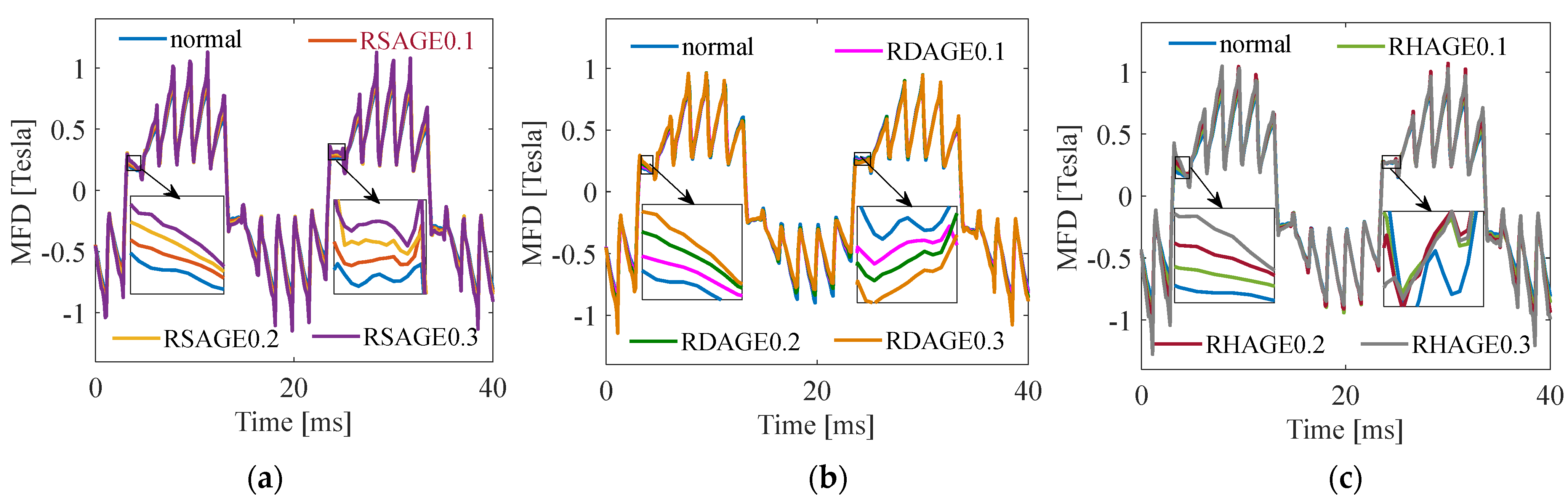
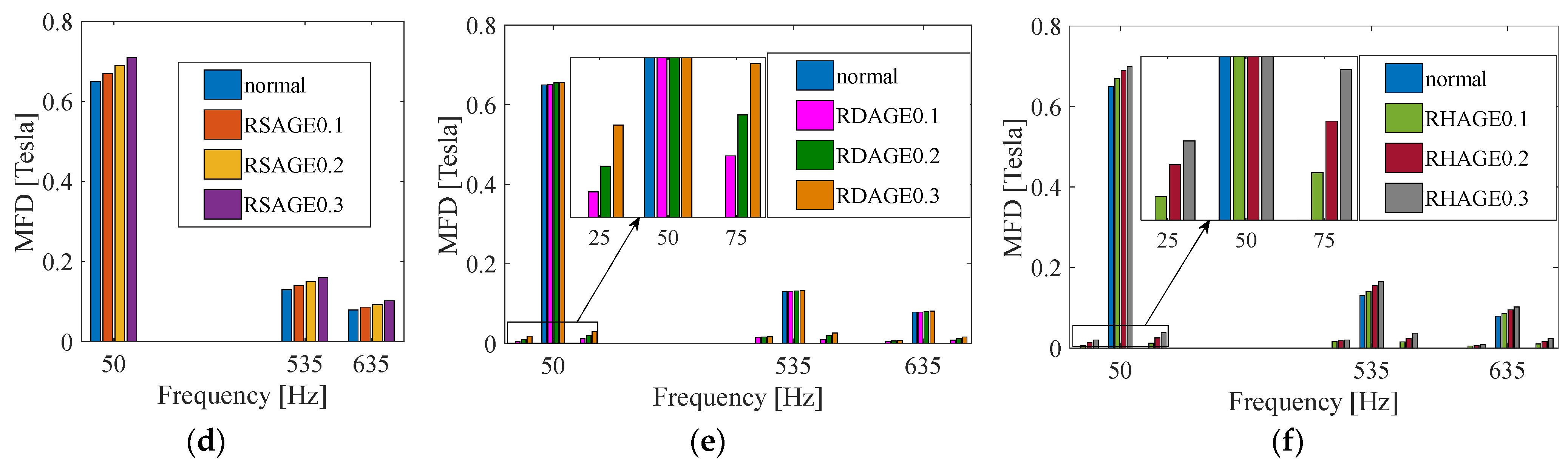
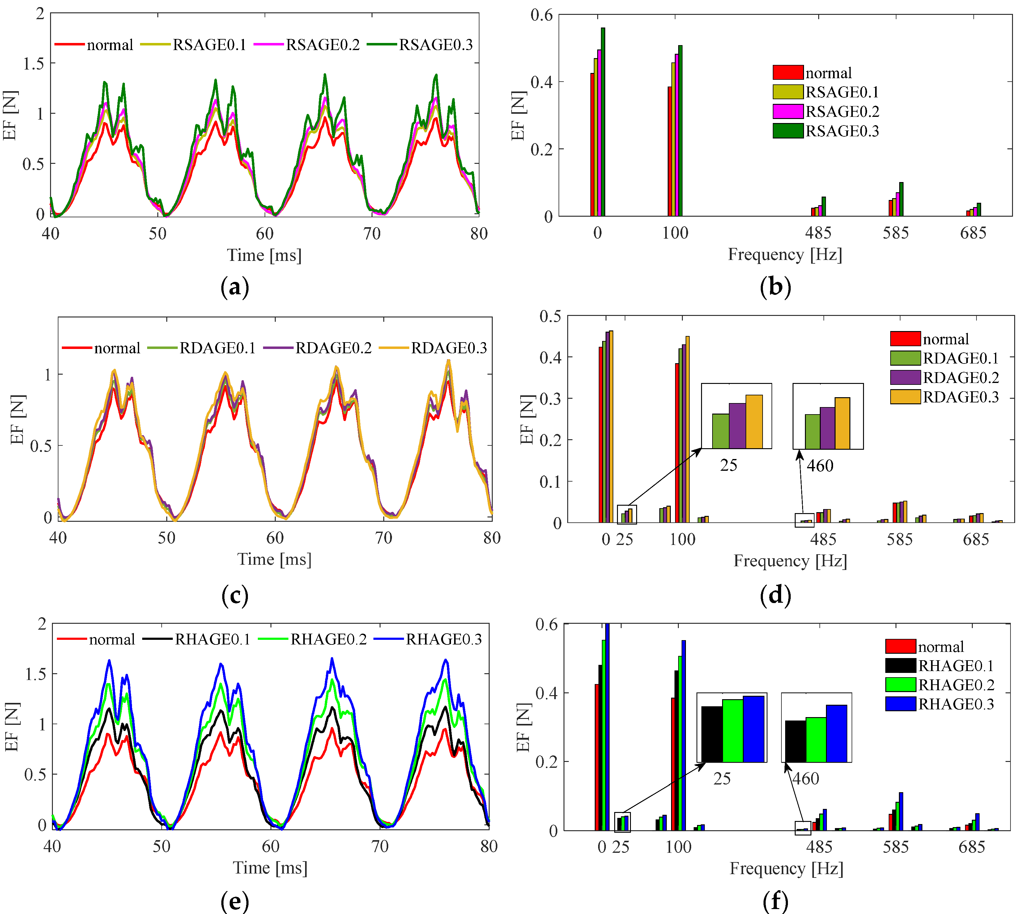
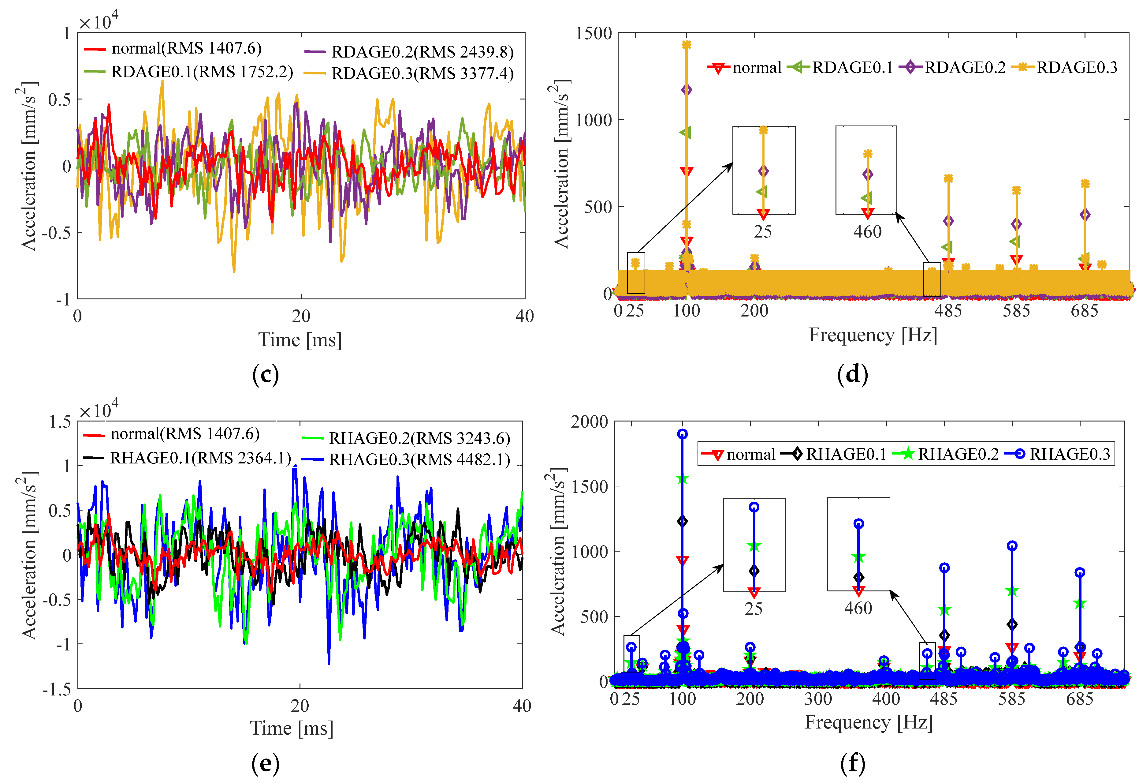
When the DFIG operates normally, the stator end windings are constantly vibrated by the action of EF. The frequency components of the vibration are fu1 ± fμ2, f1 ± fμ, f1 ± f1, 2f1. The RSAGE fault will increase the vibration amplitude of the stator winding end at the air gap reduction side without affecting the vibration frequency component.
(2)
After the RDAGE fault occurs, the stator end winding EF will generate new frequency components fu1 ± (fu2 ± fr), f1 ± (fu ± fr), and f1 ± (f1 ± fr). The vibration of the same frequency components will also be excited. With the increase in the RDAGE fault degree, the amplitudes of the vibration frequency components will also increase.
(3)
RHAGE is the accumulation of RDAGE and RSAGE, and it is consistent with the vibration frequency of the stator end winding under a RDAGE fault. The amplitude of the vibration and each characteristic frequency component will increase with the deepening of the RAGE fault.

Author Contributions

Conceptualization, Y.-L.H., M.-X.X. and D.-R.D.; methodology, Y.-L.H., W.-J.Z. and M.-X.X.; software, Y.-L.H. and M.-X.X.; validation, D.-R.D., X.-A.L. and W.Z.; formal analysis, Y.-L.H. and M.-X.X.; investigation, Y.-L.H.; resources, Y.-L.H.; data curation, Y.-L.H. and S.-T.W.; writing—original draft preparation, Y.-L.H., M.-X.X., W.-J.Z., D.-R.D., X.-A.L., W.Z. and D.G.; writing—review and editing, Y.-L.H., M.-X.X., X.-A.L. and D.G.; visualization, D.-R.D., M.-X.X. and W.Z.; supervision, Y.-L.H. and D.G.; project administration, Y.-L.H., S.-Z.S. and W.Z.; funding acquisition, Y.-L.H. and S.-Z.S. All authors have read and agreed to the published version of the manuscript.

Funding

This research was funded by the National Natural Science Foundation of China (No.52177042), in part by the Chinese Fundamental Research Funds for the Central Universities (2020MS114), in part by the Hebei Provincial Top Youth Talent Support Program ([2018]-27), and in part by Natural Science Foundation of Hebei Province of China (E2020502031).

Institutional Review Board Statement

Not applicable.

Informed Consent Statement

Not applicable.

Data Availability Statement

Not applicable.

Acknowledgments

This work was supported by the Hebei Key Laboratory of Electric Machinery Health Maintenance and Failure Prevention, North China Electric Power University, Baoding, China.

Conflicts of Interest

The authors declare no conflict of interest.

Appendix A

B α m , t = f α m , t Λ α m , t = F 0 Λ 0 cos p α m ω 1 t φ p + v F v Λ 0 cos v α m ω 1 t φ v + μ F μ Λ 0 cos μ α m ω μ t φ μ + k 1 F 0 Λ 0 λ k 1 2 cos v α m ω 1 t φ v + k 2 F 0 Λ 0 λ k 2 2 cos μ α m ω μ t φ μ · · · · · · · · · · · · · · · · · · · · · · · · · · · · · · · · · · · · · · · · · · · · · · · · normal F 0 Λ 0 cos p α m ω 1 t φ p + v F v Λ 0 cos v α m ω 1 t φ v + μ F μ Λ 0 cos μ α m ω μ t φ μ + k 1 F 0 Λ 0 λ k 1 2 cos v α m ω 1 t φ v + k 2 F 0 Λ 0 λ k 2 2 cos μ α m ω μ t φ μ + F 0 Λ 0 δ s 2 cos p ± 1 α m ω 1 t φ p + v F v Λ 0 δ s 2 cos v ± 1 α m ω 1 t φ v + μ F μ Λ 0 δ s 2 cos μ ± 1 α m ω μ t φ μ + k 1 F 0 Λ 0 λ k 1 δ s 2 cos v ± 1 α m ω 1 t φ v + k 2 F 0 Λ 0 λ k 2 δ s 2 cos μ ± 1 α m ω μ t φ μ · · · · · · · · · · · RSAGE F 0 Λ 0 cos p α m ω 1 t φ p + v F v Λ 0 cos v α m ω 1 t φ v + μ F μ Λ 0 cos μ α m ω μ t φ μ + k 1 F 0 Λ 0 λ k 1 2 cos v α m ω 1 t φ v + k 2 F 0 Λ 0 λ k 2 2 cos μ α m ω μ t φ μ + F 0 Λ 0 δ d 2 cos p ± 1 α m ( ω 1 ± ω r ) t φ p + v F v Λ 0 δ d 2 cos v ± 1 α m ( ω 1 ± ω r ) t φ v + μ F μ Λ 0 δ d 2 cos μ ± 1 α m ( ω μ ± ω r ) t φ μ + k 1 F 0 Λ 0 λ k 1 δ d 2 cos v ± 1 α m ( ω 1 ± ω r ) t φ v + k 2 F 0 Λ 0 λ k 2 δ d 2 cos μ ± 1 α m ( ω μ ± ω r ) t φ μ · · · · · · · · · · · · · · · · · · · · · · RDAGE F 0 Λ 0 cos p α m ω 1 t φ p + v F v Λ 0 cos v α m ω 1 t φ v + μ F μ Λ 0 cos μ α m ω μ t φ μ + k 1 F 0 Λ 0 λ k 1 2 cos v α m ω 1 t φ v + k 2 F 0 Λ 0 λ k 2 2 cos μ α m ω μ t φ μ + F 0 Λ 0 δ s 2 cos p ± 1 α m ω 1 t φ p + v F v Λ 0 δ s 2 cos v ± 1 α m ω 1 t φ v + μ F μ Λ 0 δ s 2 cos μ ± 1 α m ω μ t φ μ + k 1 F 0 Λ 0 λ k 1 δ s 2 cos v ± 1 α m ω 1 t φ v + k 2 F 0 Λ 0 λ k 2 δ s 2 cos μ ± 1 α m ω μ t φ μ + F 0 Λ 0 δ d 2 cos p ± 1 α m ( ω 1 ± ω r ) t φ p + v F v Λ 0 δ d 2 cos v ± 1 α m ( ω 1 ± ω r ) t φ v + μ F μ Λ 0 δ d 2 cos μ ± 1 α m ( ω μ ± ω r ) t φ μ + k 1 F 0 Λ 0 λ k 1 δ d 2 cos v ± 1 α m ( ω 1 ± ω r ) t φ v + k 2 F 0 Λ 0 λ k 2 δ d 2 cos μ ± 1 α m ( ω μ ± ω r ) t φ μ · · · · · · · · · · · · · · · · · · · · · RHAGE

Appendix B

F r = η B α m , t I L 1 = B e n d α m , t I L 1 = B e n d 2 α m , t L 1 2 v / Z L 1 2 v Λ 0 2 2 Z { F 0 2 [ 1 + cos 2 p α m ω 1 t φ p ] + 2 v F 0 F v cos [ ( p ± v ) α m ( ω 1 ± ω 1 ) t ( φ p ± φ v ) ] + 2 μ F 0 F μ cos [ ( p ± μ ) α m ( ω 1 ± ω μ ) t ( φ p ± φ μ ) ] + v 1 v 2 F v 1 F v 2 cos [ ( v 1 ± v 2 ) α m ( ω 1 ± ω 1 ) t ( φ v 1 ± φ v 2 ) ] + 2 μ v F μ F v cos [ ( μ ± v ) α m ( ω μ ± ω 1 ) t ( φ μ ± φ v ) ] + μ 1 μ 2 F μ 1 F μ 2 cos [ ( μ 1 ± μ 2 ) α m ( ω μ 1 ± ω μ 2 ) t ( φ μ 1 ± φ μ 2 ) ] } · · · · · · · · · · · · · · · · · · · · · · · · · · · · · · · · · · · · · · · · · · · · · · · · · · · · · · · · · · · · · · · · · · · · · · · · · · · · · · · · · · · · · · · · · · normal L 1 2 v Λ 0 2 2 Z { F 0 2 [ 1 + cos 2 p α m ω 1 t φ p ] + 2 v F v F 0 cos [ p ± v α m ( ω 1 ± ω 1 ) t φ p ± φ v ] + 2 μ F μ F 0 cos [ p ± μ α m ω 1 ± ω μ t φ p ± φ μ ] + F 0 2 δ s cos [ p ± p ± 1 α m ω 1 ± ω 1 t φ p ± φ p ] + v F v δ s F 0 cos [ ( p ± v ± 1 ) α m ( ω 1 ± ω 1 ) t ( φ p ± φ v ) ] + μ F μ δ s F 0 cos [ ( p ± μ ± 1 ) α m ( ω 1 ± ω μ ) t ( φ p ± φ μ ) ] + v 1 v 2 F v 1 F v 2 cos [ ( v 1 ± v 2 ) α m ( ω 1 ± ω 1 ) t ( φ v 1 ± φ v 2 ) ] + 2 μ v F μ F v cos [ ( μ ± v ) α m ( ω μ ± ω 1 ) t ( φ μ ± φ v ) ] + v F v F 0 δ s cos [ ( v ± p ± 1 ) α m ( ω 1 ± ω 1 ) t ( φ v ± φ p ) ] + v 1 v 2 F v 1 F v 2 δ s cos [ ( v 1 ± v 2 ± 1 ) α m ( ω 1 ± ω 1 ) t ( φ v 1 ± φ v 2 ) ] + μ v F μ F v δ s cos [ ( v ± μ ± 1 ) α m ( ω 1 ± ω μ ) t ( φ v ± φ μ ) ] + μ 1 μ 2 F μ 1 F μ 2 cos [ ( μ 1 ± μ 2 ) α m ( ω μ 1 ± ω μ 2 ) t ( φ μ 1 ± φ μ 2 ) ] + μ F μ F 0 δ s cos [ ( μ ± p ± 1 ) α m ( ω μ ± ω 1 ) t ( φ μ ± φ p ) ] + μ v F μ F v δ s cos [ ( μ ± v ± 1 ) α m ( ω μ ± ω 1 ) t ( φ μ ± φ v ) ] + μ 1 μ 2 F μ 1 F μ 2 δ s cos [ ( μ 1 ± μ 2 ± 1 ) α m ( ω μ 1 ± ω μ 2 ) t ( φ μ 1 ± φ μ 2 ) ] } · · · · · · · · · · · · · · · · · · · · · · · · · · · · · · · · · · · · · · · · · · · · · · · · · · · · · · · · · · · · · · · · · · · · · · · · · · · · · · · · RSAGE L 1 2 v Λ 0 2 2 Z { F 0 2 [ 1 + cos 2 p α m ω 1 t φ p ] + 2 v F v F 0 cos [ ( p ± v ) α m ( ω 1 ± ω 1 ) t φ p ± φ v ] + 2 μ F μ F 0 cos [ ( p ± μ ) α m ω 1 ± ω μ t φ p ± φ μ ] + F 0 2 δ d cos [ ( p ± p ± 1 ) α m ( ω 1 ± ω 1 ± ω r ) t φ p ± φ p ] + v F v δ d F 0 cos [ ( p ± v ± 1 ) α m ( ω 1 ± ω 1 ± ω r ) t ( φ p ± φ v ) ] + μ F μ δ d F 0 cos [ ( p ± μ ± 1 ) α m ( ω 1 ± ω μ ± ω r ) t ( φ p ± φ μ ) ] + v 1 v 2 F v 1 F v 2 cos [ ( v 1 ± v 2 ) α m ( ω 1 ± ω 1 ) t ( φ v 1 ± φ v 2 ) ] + 2 μ v F μ F v cos [ ( μ ± v ) α m ( ω μ ± ω 1 ) t ( φ μ ± φ v ) ] + v F v F 0 δ d cos [ ( v ± p ± 1 ) α m ( ω 1 ± ω 1 ± ω r ) t ( φ v ± φ p ) ] + v 1 v 2 F v 1 F v 2 δ d cos [ ( v 1 ± v 2 ± 1 ) α m ( ω 1 ± ω 1 ± ω r ) t ( φ v 1 ± φ v 2 ) ] + μ v F μ F v δ d cos [ ( v ± μ ± 1 ) α m ( ω 1 ± ω μ ± ω r ) t ( φ v ± φ μ ) ] + μ 1 μ 2 F μ 1 F μ 2 cos [ ( μ 1 ± μ 2 ) α m ( ω μ 1 ± ω μ 2 ) t ( φ μ 1 ± φ μ 2 ) ] + μ F μ F 0 δ d cos [ ( μ ± p ± 1 ) α m ( ω μ ± ω 1 ± ω r ) t ( φ μ ± φ p ) ] + μ v F μ F v δ d cos [ ( μ ± v ± 1 ) α m ( ω μ ± ω 1 ± ω r ) t ( φ μ ± φ v ) ] + μ 1 μ 2 F μ 1 F μ 2 δ d cos [ ( μ 1 ± μ 2 ± 1 ) α m ( ω μ 1 ± ω μ 2 ± ω r ) t ( φ μ 1 ± φ μ 2 ) ] } · · · · · · · · · · · · · · · · · · · · · · · · · · · · · · · · · · · · · · · · · · · · · · · · · · · · · · · · · · · · · · · · · · · RDAGE L 1 2 v Λ 0 2 2 Z { F 0 2 [ 1 + cos 2 p α m ω 1 t φ p ] + 2 v F v F 0 cos [ p ± v α m ( ω 1 ± ω 1 ) t φ p ± φ v ] + 2 μ F μ F 0 cos [ p ± μ α m ω 1 ± ω μ t φ p ± φ μ ] + F 0 2 δ s cos [ p ± p ± 1 α m ω 1 ± ω 1 t φ p ± φ p ] + v F v δ s F 0 cos [ ( p ± v ± 1 ) α m ( ω 1 ± ω 1 ) t ( φ p ± φ v ) ] + μ F μ δ s F 0 cos [ ( p ± μ ± 1 ) α m ( ω 1 ± ω μ ) t ( φ p ± φ μ ) ] + F 0 2 δ d cos [ ( p ± p ± 1 ) α m ( ω 1 ± ω 1 ± ω r ) t φ p ± φ p ] + v F v δ d F 0 cos [ ( p ± v ± 1 ) α m ( ω 1 ± ω 1 ± ω r ) t ( φ p ± φ v ) ] + μ F μ δ d F 0 cos [ ( p ± μ ± 1 ) α m ( ω 1 ± ω μ ± ω r ) t ( φ p ± φ μ ) ] + v 1 v 2 F v 1 F v 2 cos [ ( v 1 ± v 2 ) α m ( ω 1 ± ω 1 ) t ( φ v 1 ± φ v 2 ) ] + 2 μ v F μ F v cos [ ( μ ± v ) α m ( ω μ ± ω 1 ) t ( φ μ ± φ v ) ] + v F v F 0 δ s cos [ ( v ± p ± 1 ) α m ( ω 1 ± ω 1 ) t ( φ v ± φ p ) ] + v 1 v 2 F v 1 F v 2 δ s cos [ ( v 1 ± v 2 ± 1 ) α m ( ω 1 ± ω 1 ) t ( φ v 1 ± φ v 2 ) ] + μ v F μ F v δ s cos [ ( v ± μ ± 1 ) α m ( ω 1 ± ω μ ) t ( φ v ± φ μ ) ] + v F v F 0 δ d cos [ ( v ± p ± 1 ) α m ( ω 1 ± ω 1 ± ω r ) t ( φ v ± φ p ) ] + v 1 v 2 F v 1 F v 2 δ d cos [ ( v 1 ± v 2 ± 1 ) α m ( ω 1 ± ω 1 ± ω r ) t ( φ v 1 ± φ v 2 ) ] + μ v F μ F v δ d cos [ ( v ± μ ± 1 ) α m ( ω 1 ± ω μ ± ω r ) t ( φ v ± φ μ ) ] + μ 1 μ 2 F μ 1 F μ 2 cos [ ( μ 1 ± μ 2 ) α m ( ω μ 1 ± ω μ 2 ) t ( φ μ 1 ± φ μ 2 ) ] + μ F μ F 0 δ s cos [ ( μ ± p ± 1 ) α m ( ω μ ± ω 1 ) t ( φ μ ± φ p ) ] + μ v F μ F v δ s cos [ ( μ ± v ± 1 ) α m ( ω μ ± ω 1 ) t ( φ μ ± φ v ) ] + μ 1 μ 2 F μ 1 F μ 2 δ s cos [ ( μ 1 ± μ 2 ± 1 ) α m ( ω μ 1 ± ω μ 2 ) t ( φ μ 1 ± φ μ 2 ) ] + μ F μ F 0 δ d cos [ ( μ ± p ± 1 ) α m ( ω μ ± ω 1 ± ω r ) t ( φ μ ± φ p ) ] + μ v F μ F v δ d cos [ ( μ ± v ± 1 ) α m ( ω μ ± ω 1 ± ω r ) t ( φ μ ± φ v ) ] + μ 1 μ 2 F μ 1 F μ 2 δ d cos [ ( μ 1 ± μ 2 ± 1 ) α m ( ω μ 1 ± ω μ 2 ± ω r ) t ( φ μ 1 ± φ μ 2 ) ] } · · · · · · · · · · · · · · · · · · · · · · · · · · · · · · · · · · · · · · · · · · · · · · · · · · · · · · · · · · · · · · · · · · · RHAGE

References

  1. Mohammed, A.; Djurović, S. FBG Thermal Sensing Ring Scheme for Stator Winding Condition Monitoring in PMSMs. IEEE Trans. Transp. Electrif. 2019, 5, 1370–1382. [Google Scholar] [CrossRef]
  2. Li, R.; Li, H.; Hu, B.; Guo, Q. Ground wall insulation damage localization of large generator stator bar using an active Lamb waves method. IEEE Trans. Dielectr. Electr. Insul. 2017, 24, 1860–1869. [Google Scholar] [CrossRef]
  3. Maughan, C. Thermoset stator bar insulation systems. IEEE Electr. Insul. Mag. 2018, 34, 7–16. [Google Scholar] [CrossRef]
  4. Stone, G.C. Condition monitoring and diagnostics of motor and stator windings—A review. IEEE Trans. Dielectr. Electr. Insul. 2013, 20, 2073–2080. [Google Scholar] [CrossRef]
  5. Zhao, Y.; Yan, B.; Chen, C.; Deng, J.; Zhou, Q. Parametric Study on Dynamic Characteristics of Turbogenerator Stator End Winding. IEEE Trans. Energy Convers. 2014, 29, 129–137. [Google Scholar]
  6. He, Y.-L.; Xu, M.-X.; Zhang, W.; Wang, X.-L.; Lu, P.; Gerada, C.; Gerada, D. Impact of Stator Interturn Short Circuit Position on End Winding Vibration in Synchronous Generators. IEEE Trans. Energy Convers. 2021, 36, 713–724. [Google Scholar] [CrossRef]
  7. Letal, J.; Satmoko, B.; Manik, N.; Stone, G. Stator End-Winding Vibration in Two-Pole Machines: Avoiding Generator Failure. IEEE Ind. Appl. Mag. 2020, 26, 29–39. [Google Scholar] [CrossRef]
  8. Calvert, J.F. Forces in Turbine Generator Stator Windings. Trans. Am. Inst. Electr. Eng. 1931, 50, 178–194. [Google Scholar]
  9. Tegopoulos, J.A. Forces on the End Winding of Turbine-Generators I—Determination of Flux Densities. IEEE Trans. Power Appar. Syst. 1966, 2, 105–113. [Google Scholar] [CrossRef]
  10. Tegopoulos, J.A. Forces on the End Winding of Turbine-Generators II—Determination of Forces. IEEE Trans. Power Appar. Syst. 1966, 2, 114–122. [Google Scholar]
  11. Lin, R.; Laiho, A.N.; Haavisto, A.; Arkkio, A. End-Winding Vibrations Caused by Steady-State Magnetic Forces in an Induction Machine. IEEE Trans. Magn. 2010, 46, 2665–2674. [Google Scholar] [CrossRef]
  12. Albanese, R.; Calvano, F.; Mut, G.D.; Ferraioli, F.; Formisano, A.; Marignetti, F.; Martone, R.; Romano, A.; Rubinacci, G.; Tamburrino, A.; et al. Coupled Three Dimensional Numerical Calculation of Forces and Stresses on the End Windings of Large Turbo Generators via Integral Formulation. IEEE Trans. Magn. 2012, 48, 875–878. [Google Scholar] [CrossRef]
  13. Ghaempanah, A.; Faiz, J. Impact of rotor winding and stator stepped end core on magnetic force distribution on stator end-winding of turbogenerators. In Proceedings of the 2015 IEEE Jordan Conference on Applied Electrical Engineering and Computing Technologies (AEECT), Amman, Jordan, 3–5 November 2015; pp. 1–6. [Google Scholar]
  14. Lin, D.; Zhou, P.; Hu, Y.; Rosu, M. Analytical computation of end-winding leakage inductance for multi-phase AC machines. In Proceedings of the 2017 IEEE International Electric Machines and Drives Conference (IEMDC), Miami, FL, USA, 21–24 May 2017; pp. 1–6. [Google Scholar]
  15. Takeuchi, K.; Matsushita, M.; Makino, H.; Tsuboi, Y.; Amemiya, N. Finite-Element Analysis for Magnetic Flux in End Region of Synchronous Machine Using End-Winding Model. IEEE Trans. Magn. 2021, 57, 1–6. [Google Scholar] [CrossRef]
  16. Kumar, P.G.S.; Reddy, K.M.; Kumar, K.K. Reinforcement of Generator Stator End Winding Structure by Modal Analysis Approach. In Proceedings of the 2019 IEEE 4th International Conference on Condition Assessment Techniques in Electrical Systems (CATCON), Chennai, India, 21–23 November 2019; pp. 1–5. [Google Scholar]
  17. Jiang, H.-C.; He, Y.-L.; Tang, G.-J.; Xu, M.-X. A Comprehensive Analysis on Transient Electromagnetic Force Behavior of Stator Windings in Turbo-Generator. Math. Probl. Eng. 2018, 2018, 4189609. [Google Scholar] [CrossRef]
  18. Tang, G.-J.; Jiang, H.-C.; He, Y.-L.; Meng, Q.-F. Electromagnetic Forces and Mechanical Responses of Stator Windings before and after Rotor Interturn Short Circuit in Synchronous Generators. Math. Probl. Eng. 2020, 2020, 5892312. [Google Scholar] [CrossRef]
  19. He, Y.-L.; Sun, K.; Wu, Y.; Zhao, H.-S.; Wang, X.-L.; Gerada, C.; Gerada, D. Impact of Static Air-Gap Eccentricity on Thermal Responses of Stator Winding Insulation in Synchronous Generators. IEEE Trans. Ind. Electron. 2022, 69, 13544–13554. [Google Scholar] [CrossRef]
  20. Dorrell, D.G.; Salah, A.; Guo, Y. The Detection and Suppression of Unbalanced Magnetic Pull in Wound Rotor Induction Motors Using Pole-Specific Search Coils and Auxiliary Windings. IEEE Trans. Ind. Appl. 2017, 53, 2066–2076. [Google Scholar] [CrossRef]
  21. He, Y.-L.; Xu, M.-X.; Xiong, J.; Sun, Y.-X.; Wang, X.-L.; Gerada, D.; Vakil, G. Effect of 3D Unidirectional and Hybrid SAGE on Electromagnetic Torque Fluctuation Characteristics in Synchronous Generator. IEEE Access 2019, 7, 100813–100823. [Google Scholar] [CrossRef]
  22. Da, Y.; Shi, X.; Krishnamurthy, M. A New Approach to Fault Diagnostics for Permanent Magnet Synchronous Machines Using Electromagnetic Signature Analysis. IEEE Trans. Power Electron 2013, 28, 4104–4112. [Google Scholar] [CrossRef]
  23. Attestog, S.; Khang, H.V.; Robbersmyr, K.G. Detecting Eccentricity and Demagnetization Fault of Permanent Magnet Synchronous Generators in Transient State. In Proceedings of the 2019 22nd International Conference on Electrical Machines and Systems (ICEMS), Harbin, China, 11–14 August 2019; pp. 1–5. [Google Scholar]
  24. He, Y.-L.; Zhang, Z.-J.; Tao, W.-Q.; Wang, X.-L.; Gerada, D.; Gerada, C.; Gao, P. A New External Search Coil Based Method to Detect Detailed Static Air-Gap Eccentricity Position in Nonsalient Pole Synchronous Generators. IEEE Trans. Ind. Electron. 2021, 68, 7535–7544. [Google Scholar] [CrossRef]
  25. Faiz, J.; Ebrahimi, B.M.; Akin, B.; Toliyat, H.A. Finite-Element Transient Analysis of Induction Motors Under Mixed Eccentricity Fault. IEEE Trans. Magn. 2008, 44, 66–74. [Google Scholar] [CrossRef]
  26. Bruzzese, C.; Joksimovic, G.; Santini, E. Static eccentricity detection in synchronous generators by field current and stator Voltage Signature Analysis-Part II: Measurements. In Proceedings of the XIX International Conference on Electrical Machines—ICEM, Rome, Italy, 6–8 September 2010; pp. 1–5. [Google Scholar]
  27. He, Y.-L.; Wang, Y.; Jiang, H.-C.; Gao, P.; Yuan, X.-H.; Gerada, D.; Liu, X.-Y. A Novel Universal Model Considering SAGE for MFD-Based Faulty Property Analysis Under RISC in Synchronous Generators. IEEE Trans. Ind. Electron. 2022, 69, 7415–7427. [Google Scholar] [CrossRef]
  28. Shu-ting, W.; Yu-ling, H. Investigation on stator and rotor vibration characteristics of turbo-generator under air gap eccentricity fault. Trans. Can. Soc. Mech. Eng. 2011, 35, 161–176. [Google Scholar]
  29. Zhang, J.; Xiong, X.; Zhou, Y.; Wang, K. Rotor Eccentric Diagnosis of High-Voltage Motor in Nuclear CRF Pump Using Vibration Signals. In Proceedings of the 2021 7th International Conference on Condition Monitoring of Machinery in Non-Stationary Operations (CMMNO), Guangzhou, China, 11–13 June 2021; pp. 282–286. [Google Scholar]
  30. Song, Z.; Liu, C.; Zhao, H.; Huang, R. Nonlinear Force and Vibration Analysis of an Interior Permanent Magnet Synchronous Generator with Eccentricity Detection. IEEE/ASME Trans. Mechatron. 2021. [Google Scholar] [CrossRef]
  31. Zhijun, S.; Dongsheng, Y.; Dianlin, J. Electromagnetic Vibration Characteristics Analysis of Induction Motor in Eccentric State. In Proceedings of the 12th National Conference on Vibration Theory and Applications, Nanning, China, 2 October 2017; pp. 1037–1043. [Google Scholar]
  32. Dorrell, D.G.; Hermann, A.; Jensen, B.B. Analysis of unbalanced magnetic pull in wound rotor induction machines using finite element analysis—Transient, motoring and generating modes. In Proceedings of the IECON 2013—39th Annual Conference of the IEEE Industrial Electronics Society, Vienna, Austria, 10–13 November 2013; pp. 7307–7312. [Google Scholar]
Figure 1. Schematic diagram of generator eccentricity: (a) RSAGE; and (b) RDAGE.
Energies 15 06426 g001
Figure 2. Stator core and winding: (a) real winding; (b) 3D models; and (c) mechanical model.
Energies 15 06426 g002
Figure 3. FEA setup: (a) three-dimensional models of DFIG; (b) external circuit; and (c) eccentricity setting interface.
Energies 15 06426 g003
Figure 4. Experimental setup: (a) DFIG; (b) drive motor and control cabinet; (c) acquisition equipment; (d) load bank; and (e) RAGE setup.
Energies 15 06426 g004
Figure 5. The MFD at minimum air gap under normal and RAGE conditions: (a) the MFD time domain in RSAGE; (b) the MFD time domain in RDAGE; (c) the MFD time domain in RHAGE; (d) the frequency domain in RSAGE; (e) the frequency domain in RDAGE; and (f) the frequency domain in RHAGE.
Energies 15 06426 g005aEnergies 15 06426 g005b
Figure 6. The end winding EF by FEA: (a,b) the time domain and frequency domain in RSAGE; (c,d) the time domain and frequency domain in RDAGE; and (e,f) the time domain and frequency domain in RHAGE.
Energies 15 06426 g006
Figure 7. The end winding vibration by experiment: (a,b) the time domain and frequency domain in RSAGE; (c,d) the time domain and frequency domain in RDAGE; and (e,f) the time domain and frequency domain in RHAGE.
Energies 15 06426 g007aEnergies 15 06426 g007b
Table 1. Frequency components before and after RAGE fault.
CaseMFDEF
Normalfμ, f1fu1 ± fμ2, f1 ± fμ, f1 ± f1, 2f1
RSAGEfμ, f1fu1 ± fμ2, f1 ± fμ, f1 ± f1, 2f1
RDAGEfμ ± fr, fμ, f1 ± fr, f1fu1 ± fμ2, f1 ± fμ, f1 ± f1, 2f1, fu1 ± (fu2 ± fr), f1 ± (fu ± fr), f1 ± (f1 ± fr)
RHAGEfμ ± fr, fμ, f1 ± fr, f1fu1 ± fμ2, f1 ± fμ, f1 ± f1, 2f1, fu1 ± (fu2 ± fr), f1 ± (fu ± fr), f1 ± (f1 ± fr)
Table 2. Parameters of the DFIG Prototype Generator.
ParametersValueParametersValue
Rated capacity5.5 kWRated rotating speednr= 1500 rpm
Stator core lengthl = 155 mmStator external diameter210 mm
Parallel branchesa = 2Rotor external diameter134 mm
Air-gap length1 mmPower factorcos φ = 0.8
Rated voltage380 VStator slotsZ1 = 36
Pole pairsp = 2Rotor slotsZ2 = 24
Table 3. Frequency components of MFD, EF before and after RAGE fault (FEA and experiment).
CaseMFD (FEA)EF (FEA and Experiment)
Normal50, 535, 6350, 100, 485, 585, 685
RSAGE50, 535, 6350, 100, 485, 585, 685
RDAGE50, 535, 635,
25, 75, 510, 560, 610, 660
0, 100, 485, 585, 685
25, 75, 125, 460, 510, 560, 610, 660, 710
RHAGE50, 535, 635,
25, 75, 510, 560, 610, 660
0, 100, 485, 585, 685
25, 75, 125, 460, 510, 560, 610, 660, 710
Publisher’s Note: MDPI stays neutral with regard to jurisdictional claims in published maps and institutional affiliations.

