Review

Techno-Economic Analysis of Hydrogen Storage Technologies for Railway Engineering: A Review

1
Birmingham Centre for Rail Research and Education, University of Birmingham, Birmingham B152TT, UK
2
School of Mechanical and Engineering, Southeast University, Nanjing 210000, China
*
Authors to whom correspondence should be addressed.
Energies 2022, 15(17), 6467; https://doi.org/10.3390/en15176467
Submission received: 6 August 2022 / Revised: 30 August 2022 / Accepted: 30 August 2022 / Published: 5 September 2022

Abstract

:
According to the specific requirements of railway engineering, a techno-economic comparison for onboard hydrogen storage technologies is conducted to discuss their feasibility and potentials for hydrogen-powered hybrid trains. Physical storage methods, including compressed hydrogen (CH2), liquid hydrogen (LH2), and cryo-compressed hydrogen (CcH2), and material-based (chemical) storage methods, such as ammonia, liquid organic hydrogen carriages (LOHCs), and metal hydrides, are carefully discussed in terms of their operational conditions, energy capacity, and economic costs. CH2 technology is the most mature now but its storage density cannot reach the final target, which is the same problem for intermetallic compounds. In contrast, LH2, CcH2, and complex hydrides are attractive for their high storage density. Nevertheless, the harsh working conditions of complex hydrides hinder their vehicular application. Ammonia has advantages in energy capacity, utilisation efficiency and cost, especially being directly utilised by fuel cells. LOHCs are now considered as a potential candidate for hydrogen transport. Simplifying the dehydrogenation process is the important prerequisite for its vehicular employment. Recently, increasing novel hydrogen-powered trains based on different hydrogen storage routes are being tested and optimised across the world. It can be forecasted that hydrogen energy will be a significant booster to railway decarbonisation.

1. Introduction

Long-term extensive use of fossil fuels contributes to increasingly severe environment problems. Nowadays, deep decarbonisation has become a topical issue all over the world. Carbon neutral plans have been made by worldwide nations and organisations to reduce greenhouse gas (GHG) emissions and slow global warming [1,2,3,4].
Recently, the transportation sector consumed about 57 Mtoe (over 33% of the whole energy consumption) every year in the UK [5,6]. As an important component of transportation, rail transport is looking at options to replace its diesel-powered trains against the background of climate change and the need for fast and consistent decarbonisation of the entire energy system [7]. Major investment plans are underway to install and upgrade railway electrification to pave the way for a cleaner future for the railway industry [8]. Rail electrification provides numerous benefits including quicker and quieter journeys, increased capacity, and being more environmentally friendly. However, it requires giant infrastructure construction at a significant cost. For the remote routes where electrification is not economically viable, hydrogen and fuel cell technology offer complimentary sources of traction. Meanwhile, it enables trains with higher power, faster refuelling, and long endurance [9,10].
The first hydrogen-powered locomotive was developed, designed, and demonstrated in America in 2002 [7]. Its onboard hydrogen storage system is based on metal hydrides technology. A seven-year project beginning in 2003, aiming to apply hydrogen to rail heavy haul industry, was jointly conducted by America and Japan [11]. The power system of the target locomotive includes 250 kW fuel cell stacks and 1250 kW batteries. Afterwards, Japan trialled a rail car during 2006 to 2007, which used 35 MPa CH2 storage technology. Then, two rail cars equipped with CH2 tanks, powered by 120 kW PEMFC and 36 kWh auxiliary batteries, continued to be tested in Japan [12].
An increasing number of hydrogen-powered trains have been put into operation in recent years. South Africa launched the world’s first fuel cell-powered mining locomotive in 2012 [13]. A hydrogen-powered rail tram began to be tested from the same year in Chengdu, China, and was then put into service in 2014 [14]. On 16 September 2018, Coradia Ilint [15], manufactured by Alstom, entered service in Germany, with hydrogen storage tanks placed at the top of carriages. It has been operated on a 100 km route from Cuxhaven to Buxtehude. The UK’s first hydrogen-powered train, named ‘HydroFLEX’ [16], was jointly developed by University of Birmingham and Porterbrook Co. It was unveiled in 2019, successfully received a mainline run in 2020, and was showcased at COP26, Glasgow, in 2021. China’s first hydrogen fuel cell hybrid locomotive started trial runs for coal transport in October 2021. It announced that it was able to reduce carbon emissions by 80 kg/km per 10,000 tons’ load compared with traditional diesel-powered locomotives. Researchers from East Japan Railway also tested and optimised their H2 train, named HYBARI [17]. They installed the whole traction equipment under the floor and realised the downsizing of the power system.
Developing high-density hydrogen storage technologies with acceptable cost and reliable security is always the key issue for hydrogen-powered vehicles [18,19]. At present, hydrogen storage technologies can be catalysed into two main groups. The first category is physical storage methods, including compressed gas hydrogen (CH2), cold-compressed hydrogen, liquid/cryogenic hydrogen (LH2), and cryo-compressed hydrogen (CcH2). Another group is material-based (chemical) storage, including adsorption and absorption. Several storage technologies have been tested for onboard power systems and have shown their different characteristics. CH2 storage technology [20,21,22] is the most well-established now, whose normal storage pressures are 35 MPa and 70 MPa. Its gravimetric and volumetric density can achieve 5.5 wt% and 3.6 MJ/L, respectively, but it still does not reach the final targets set by DOE (Department of Energy, America). Storage capacity of LH2 and CcH2 is close to the target, and they are regarded as the potential technologies to achieve the goals [18,23,24,25]. Nevertheless, due to unavoidable heat leakage, LH2 cannot be stored without loss for a long time. Liquefaction and a high standard for insulation also raise its energy consumption during production and raise the total cost of ownership for vehicles. CcH2 combines the advantages of long dormancy time from CH2 and high storage density from LH2. Low technology maturity and infrastructure to be constructed slows its large-scale onboard application. Intermetallic compounds [26] are used in many industry areas but their low hydrogen storage capacities (<2 wt%), slow kinetics, and complicated activation procedures make them hard to be vehicle-mounted hydrogen carriers. In contrast, complex hydrides [27] overcome the drawback on the storage capacities, but it is necessary to lower their operating conditions before onboard use. Similarly, chemical hydrides and magnesium-based alloys [28,29,30] have favourable hydrogen storage capacities. However, chemical hydrides are irreversible, which means it is difficult to refuel them quickly. Mg-based alloys have poor thermodynamic and kinetic properties, increasing the difficulty of their dehydrogenation process. Ammonia catches increasing attention now for its high hydrogen capacity and relatively convenient storage. Moreover, it can be utilised though three ways, direct combustion, fuel cells (after dehydrogenation and purification), and direct fuel cells. Diversified utilisation methods mean that ammonia can adapt to different industrial demands and transportation requirements [31,32]. Liquid organic hydrogen carriers (LOHCs) are discussed a lot for hydrogen transportation because of their large hydrogen storage capacity. Simplifying their operation conditions is a prerequisite before they can efficiently be used as the hydrogen carriers for trains. The dehydrogenation process, refuelling time, and safety issues are the concerns for their onboard utilisation.
Apart from the technologies mentioned above, some other storage methods receive continued attention as well, such as hydrate hydrogen, physisorption-based storage, and composite storage. At present, the hydrogen storage capacity of hydrate hydrogen storage is lower than 1 wt% in most cases, and their operation pressure is too high, which restricts its onboard application [33]. For physisorption-based materials, the Department of Energy (DOE), America, published a summative report on hydrogen sorption [34,35]. They have acceptable hydrogen capacity but low temperature (usually 77 K) and high pressure is a must. For the composite storage mode, it includes a metal hydrides compressor and cryo-adsorption on active carbon or porous materials, etc. [36,37,38,39]. Improvement of the hydrogen capacity is attained to some extent but is accompanied by a more complicated system and a rise in cost. Most of these technologies are in their lab stage. There are few relative data sources in the industry that can be found now. Hence, we do not spend much time discussing these methods and just focus on the mainstream hydrogen storage technologies discussed in the last paragraph.
In this paper, existing hydrogen-powered trains are presented and discussed. Most of them are equipped with 35 MPa CH2 with Type III tanks. Moreover, different types of hydrogen storage technologies are evaluated for the hydrogen storage density, economic cost, operation conditions, and development prospect. Furthermore, according to specific requirements for railway engineering, suggestions on the promising hydrogen storage methods for next-generation hydrogen-powered locomotives are provided.

2. Compressed Hydrogen Storage

Currently, compressed gas hydrogen technology is the most well-established among all the hydrogen storage technologies. It involves the physical storage of compressed hydrogen in high-pressure vessels and operates at high pressures, as high as 70 MPa. Its mature upstream and middle supply chain, including the production plants and refuelling stations, enable high-pressure hydrogen refuelling with relatively fast speeds and strong compatibility for vehicles. There are four standard types of CH2 vessels, as shown in Table 1:
Because of the low H2 gravimetric capacity of Type I and Type II, they are not suited for vehicular use. Type III and type IV vessels are widely employed for H2-powered vehicles now. Type III vessels are composed of a metal liner with full composite overwrap, generally aluminium, with a carbon fibre composite. Type IV vessels have an all-composite construction featuring a polymer (typically high-density polyethylene) liner with carbon fibre or hybrid carbon/glass fibre composite. Type III cylinders with 35 MPa storage pressure are usually equipped on heavy-loaded vehicles, from commercial buses, trucks, to locomotives. Type IV cylinders with 70 MPa storage pressure are employed for light-duty vehicles, mostly cars, such as the Toyota Mirai. A comparison between the two storage pressure types is shown in Table 2:
It can be found from Table 2 that the system gravimetric capacity of CH2 technology can mostly meet requirements of DOE (2025), but its system volumetric capacity is still far from the final target. Another unexpected result is that the gravimetric capacity of a 70 MPa storage vessel is less than that of a 35 MPa system. To withstand higher pressure, more CF must be wrapped around tanks, which increases its self-weight and raises its cost. Reducing the storage system cost is another focus point on the aspect of the industrial mass production. As shown in Figure 1, cost of CF and balance of plant (BOP) accounts for a large proportion of the total cost. Hopefully, it is predicted by DOE that the system cost will drop from 22.94 USD/kWh (10 k systems per year) to 14.07 USD/kWh (500 k systems per year).
Recently revealed hydrogen-powered trains all adopt CH2 hydrogen storage technology, including HydroFLEX (2019) [6,16,45,46], CRRC (2021), and Coradia ilint, Alstom (2018) [47,48], as shown in Table 3.
A key issue for CH2-powered train designs is the arrangement for mounting its new power system, including the hydrogen storage system, fuel cell system, auxiliary power, electric motors, etc. A large space is required to place high-power proton exchange membrane fuel cell (PEMFC) stacks, as well as the hydrogen storage system. Because of requirements for long range use, quantities of hydrogen must be taken to ensure enough power is provided. The drawback of the hydrogen storage capacity of CH2 results in multi-groups hydrogen tanks needing to to be installed. To tackle the problem of space arrangement, the Coradia ilint train places PEMFC stacks and hydrogen tanks above its carriages, as shown in Figure 2. HydroFLEX 1.0 changes its original PMOS carriage to a power system carriage, as shown in Figure 3, installing fuel cell systems, four Luxfer W205N Type III hydrogen tanks, batteries, control system, and electric motors, etc. The arrangement reduces passenger accommodation, but it is deemed to be within tolerance for passenger crush loading. Noticeably, the next-generation HydroFLEX will use more hydrogen storage tanks to enlarge its range, which has a considerable influence on the space assignment. Miniaturisation and lightweight design for the power system is necessary for current locomotives, but it is still a problem remaining to be solved with current CH2 storage technology.
To summarise, compressed gas hydrogen storage technology is unmatched in the aspect of maturity, which makes it the most popular for onboard applications now. Nevertheless, low hydrogen capacity will restrict its further application on heavy-load locomotives. The requirements of long-range and high-power heavy haul railways result in the locomotive needing to be equipped with multiple groups of hydrogen tanks. This brings a larger space occupation and complex gas supply line, which affect its safety, stability, and economics. Enlarging its storage density and reducing its cost will continuously be important research points in the future.

3. Liquid Hydrogen Storage

Historically, liquid hydrogen storage technology has been the preferred method to increase hydrogen density for bulk transport and storage [50]. The density of liquid hydrogen is 70.78 kg/m3. Current technology can refrigerate hydrogen to a temperature of 20 K to be stored in vacuum-insulated vessels at 0.6 MPa [51]. It has great superiority over CH2 storage on the system volumetric storage capacity, which can reach up to 36.6 kg/m3. Another typical advantage of LH2 is its relatively low cost in most aspects. DOE presented a report in 2020, which compares the cost of the whole industry chain between CH2 and LH2 based on some specific scenarios as shown in Table 4. Indeed, the liquefication process consumes large quantities of energy. Moreover, LH2 costs less than CH2 in other processes. Fortunately, according to R.K Ahluwalia [52], large scale production with large plants will reduce its production cost, the liquefication capital cost will drop to 2500 USD/kg per day when its yield finally rises to 100 k tons per day.
Considering its energy storage density, cryogenic liquid hydrogen storage is an ideal method for heavy-duty vehicles. However, its gravimetric capacity is not completely satisfactory, owing to the high demand for insulation. Thick thermal insulation materials need to be wrapped in an LH2 vessel, causing a large cost, space, and gravity occupation. Moreover, the liquefaction process requires 4–10 kW/h per kilogram, accounting for over 30% of the energy stored, theoretically, more than twice than H2 compression. This percentage is even higher while in practical production. Another challenge for LH2 application is that it is difficult for long term storage, with 0.2–0.3% d-1 loss in well-insulated tankers and up to 3% d-1 in vehicle-mounted vessels [54]. Under cryogenic conditions, spontaneous ortho-to-para conversion would release non-negligible heat, e.g., 702 kJ/kg at 20 K [55], which would promote hydrogen evaporation. Although well insulated, absorbing heat from the atmosphere is unavoidable because of the huge temperature difference between the inner tank and the atmosphere. Inner pressure rises quickly as LH2 vaporises. Venting measures must be taken to prevent danger. Furthermore, more attention should be paid to its refuelling technology. The gas–liquid two-phase flow exists while filling, which slows its filling speed. It is a non-negligible problem when LH2-powered systems are mounted on locomotives [56].
LH2 is always mentioned in hydrogen transport because of its high H2 capacity and low transport cost, especially in marine environments. In 2019, Kawasaki Heavy Industries, Japan, launched the world’s first liquid hydrogen transport ship, Suiso Frontier [57]. It has a mounted 1250-cubic-meter, vacuum-insulated double-shell-structure stainless steel LH2 cargo tank, specially developed by Harima Works.
There are no existing LH2-powered locomotives yet, though LH2 has been used in the military and aerospace fields for a long time. The onboard LH2-based system is well established by Linde as shown in Figure 4. Therefore, LH2-powered trains can be considered as a great challenge, as well as a commercial opportunity. This is noticed by some institutions and corporations, such as the Korean Railroad Research Institute (KRRI) and Wabtec from the US [58]. KRRI announced details of a project to develop the world’s first liquefied hydrogen-based traction system in 2021. The project aims to develop a liquefied hydrogen hybrid propulsion system, high-insulation cryogenic storage technology, and a fast-refuelling technology. The LH2-fuel cell system will support operation at up to 150 km/h and offer a range of 1000 km as well as reduce refuelling times by 20% compared with 70 MPa compressed hydrogen trains. Similarly, in heavy-duty fields, a prototype long-haul truck named Mercedes-Benz Trucks-GenH2 [59] received approval from German authorities for road use, with a range of up to 1000 km.
From a technical point of view, LH2 storage technology is favourable for its high storage capacity, especially for heavy-loaded vehicles. Because of the large liquefication consumption and short dormancy time, much effort is needed to conquer these challenges for onboard applications. Additionally, transporting hydrogen over a long range by LH2 technology is a good choice and is feasible because of its high purity and hydrogen capacity. Comprehensively speaking, rail transit equipment based on LH2 is basically consistent with heavy-duty vehicles in the equipment route of hydrogen filling and supply. Due to the higher requirements of power, longer endurance, and lower refuelling flexibility of railway transit equipment, higher demand on hydrogen storage efficiency is raised to reduce the filling frequency. Under the premise of the complete LH2 infrastructure, setting up special LH2 refuelling equipment along the track to provide special filling services is an important prerequisite for the development of LH2 railway transit.

4. Cryo-Compressed Hydrogen Storage

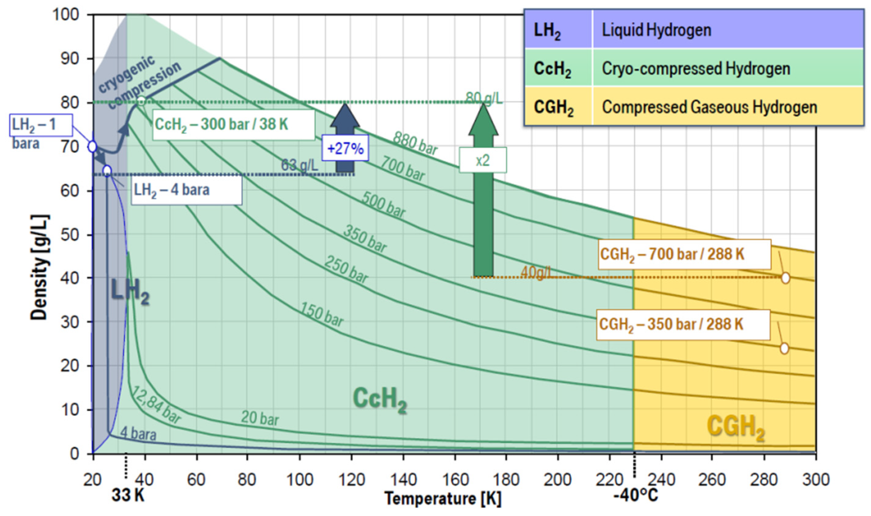
Cryo-compressed hydrogen storage (CcH2) refers to the storage of H2 at cryogenic temperature in a vessel that can be pressurised (nominally 25–30 MPa) [61,62,63]. As shown in Figure 5, the volumetric storage capacity of liquid hydrogen rises with pressure increases. For example, when the pressure of LH2 rises from 0.1 MPa to 23.7 MPa at 21 K, its density increases from 70 g/L to 87 g/L, and the gravimetric capacity also reaches 7.4 wt%. Compared with CH2 storage technology, CcH2 storage technology is superior for its H2 storage capacity, which has the potential to reach the target set by DOE. In contrast to LH2 technology, CcH2 overcomes the limitation of dormancy time, which is three times that of LH2.
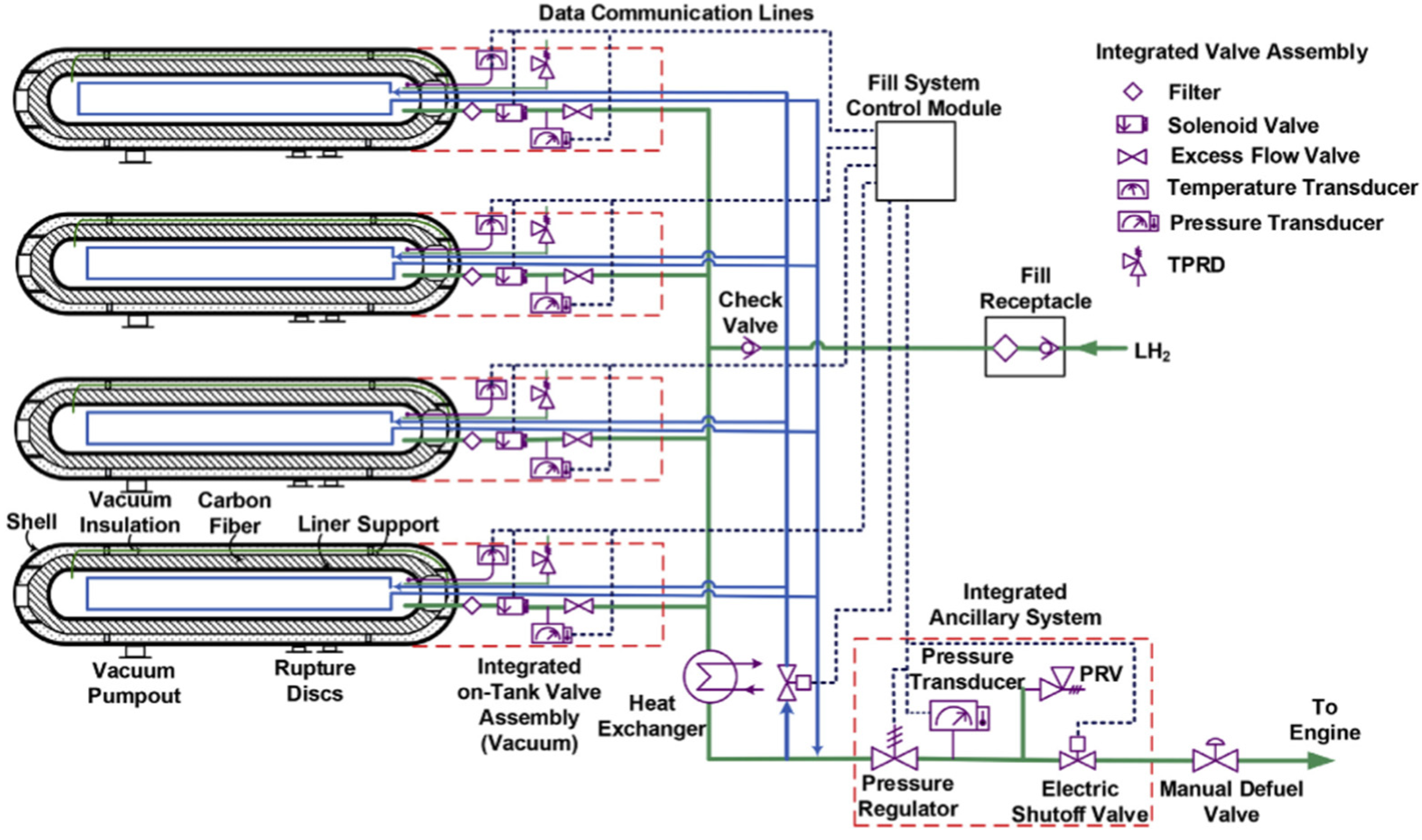
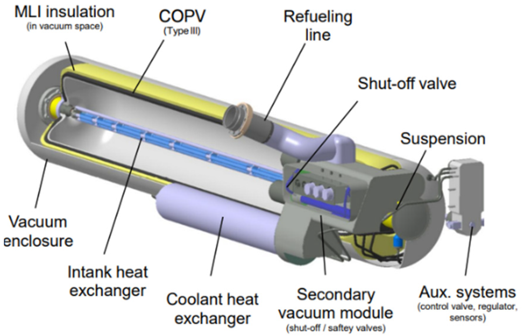
Lawrence Livermore National Laboratory (LLNL), California, developed a novel CcH2 vessel and the onboard storage and supply system for fuel cell stacks as shown in Figure 6 [24,64,65]. Temperature and pressure management of this system is carefully treated because of the high-pressure and cryogenic characteristics of CcH2. Compared to the Type III 35 MPa H2 system, the 50 MPa CcH2 storage system can achieve 91%, 175%, and 21% improvement in gravimetric capacity, volumetric capacity, and system cost reduction, respectively. Meanwhile, it enables the loss-free dormancy exceeding over 7 days with an initial 85% load. According to these attractive performances, many researchers participate in promoting the development of CcH2 technology [66,67,68]. Optimisation designs for onboard CcH2 storage systems are made to enlarge its energy utilisation efficiency. LLNL and Argonne National Laboratory (ANL) have made simulations for CcH2 storage systems for freight and regional locomotives to validate their feasibility in railway engineering. With the annual production of CcH2 systems rising to 500 k, its system cost will reduce to 14.93 USD/kWh [69]. BMW AG (Munich, Germany) released its prototype cryo-compressed cars for testing, as shown in Figure 7. The vessel was tested by LLNL from 2017 to 2018. No degradation of the vessel was observed after 1000+ cycles to 30 MPa [70,71].
Detailed cost comparison among CcH2, CH2, and cold-cH2 has been conducted by DOE, 2018 [72]. The results are shown in Table 5. It can be seen that 350 bar and 500 bar CcH2 storage vessels have a price advantage compared with 350 bar CH2 storage vessels because of its lower requirement for composites (mainly CF).
To conclude, CcH2 storage combines the advantages of CH2 storage and LH2 storage, which results in a high hydrogen storage capacity and long loss-free dormancy time. Core components of the CcH2 storage system have experimentally validated the requirements of high-density storage, rapid refuelling (without H2 loss), safety, and structural durability. However, this technology is still in its prototype stage. Relevant international standards need to be formulated. Infrastructure and supporting facilities will reduce its cost in the future. It can be forecasted that CcH2 is a prospective option for hydrogen-powered hybrid trains in the future.

5. Liquid Organic Hydrogen Carriers (LOHCs)

In 2021, Siemens Mobility and the Helmholtz Institute Erlangen-Nuremberg for Renewable Energy (HI ERN), Germany, declared to jointly retrofit Vectron mainline locomotives’ power system with LOHCs technology [73], which indicates that LOHCs technology could be another candidate for railway engineering.
LOHCs are liquids or low-melting solids that can be reversibly hydrogenated and dehydrogenated under specific conditions with the assistance of catalysts [74]. Though their application on mobility is still under discussion, LOHCs are usually considered as a promising solution for hydrogen transportation over a long distance, which are better than physical storage methods in terms of power consumption and cost [75,76].
Properties of several LOHCs are listed in Table 6. Their hydrogen gravimetric capacities range from 6 wt% to 8 wt%, superior to CH2 storage. Moreover, LOHCs are favourable for their relatively low cost, high degree of safety, and excellent reversibility [75,77,78]. Some researchers consider toluene-MCH as one of the most feasible H2 carriers among LOHCs because of its relative maturity [79,80]. It was initially tested in the Euro-Quebec Hydro-Hydrogen project in the 1980s. Relevant regulations for storage and transportation have not yet been established. Additionally, its hydrogenation and dehydrogenation cycle has been successfully demonstrated by Chiyoda Corporation, Japan.
A.T. Wijayanta, etc. [79] made detailed research on toluene-MCH, including its utilisation methods, well-to-wheel efficiency, cost analysis, and future development. According to their research, toluene-MCH can be used by direct combustion and fuel cells after dehydrogenation, whose total energy efficiencies are 26% and 45%, respectively. Compared with other hydrogen storage technologies, toluene-MCH has advantages in the production stage, which consumes only 25% of the total energy stored in H2. During transportation, its loss can be neglected. Nevertheless, much energy will be consumed during dehydrogenation, which is a common problem for other LOHCs. In his forecasting model, the cost of Toluene-MCH can be reduced to JPY 31.5 (USD 0.26) *Nm−3-H2 in 2030 and further drop to JPY 27.3 (USD 0.22) *Nm−3-H2 in 2050.
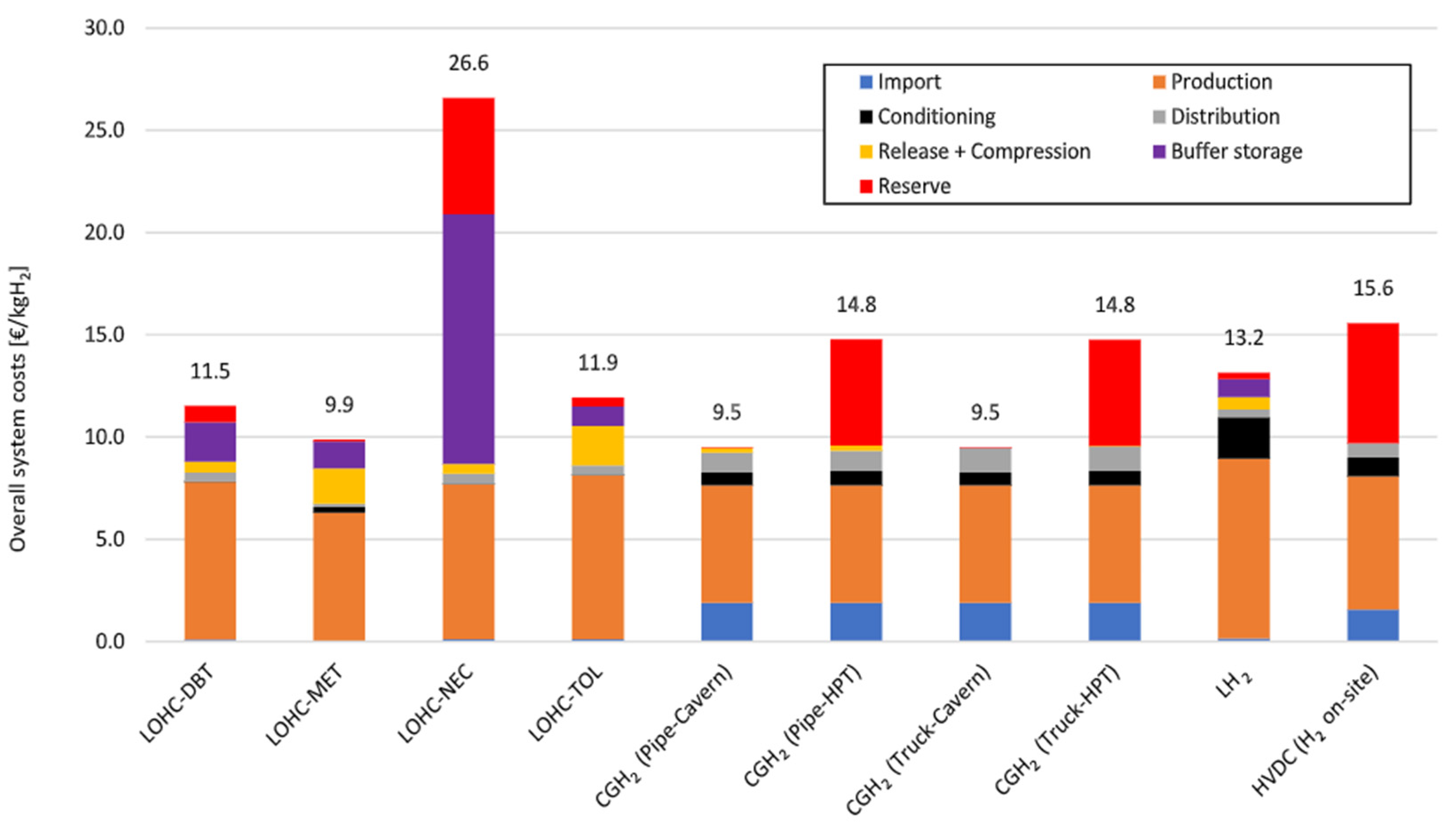
M. Niermann, etc. [75] also comprehensively compared various LOHCs with non-LOHCs technology. Figure 8 illustrates that methanol is a suitable candidate for hydrogen delivery and import, as its overall system costs only EUR 9.9 (USD 10.8)/kg-H2. Dibenzytoluene and toluene are also possible options with the assumption that their dehydrogenation process is assisted by wasted heat. Their costs are EUR 11.5 (USD 12.65) and EUR 11.9 (USD 13.09)/kg-H2, following methanol.
Besides the whole supply chain of LOHCs, their specific application processes, especially dehydrogenation, also receive much attention. Heat supply methods and integration are believed to be key for LOHCs’ application [80,82]. According to Table 6, no matter the kind of LOHCs, their reactions need to absorb heat to achieve high temperature. It requires the onboard thermal management system to undertake heavy responsibility. On the other hand, the high heat supply requirement also offers the chance to reuse wasted energy generated from the fuel cell stacks, as their heat efficiency is around 50%. Nearly half of the energy stored in hydrogen dissipates in the form of heat.
In summary, LOHCs are attractive for their high hydrogen storage capacities. Another outstanding characteristic of LOHCs is that they can be seamlessly integrated with current technologies and industries. This results in cost reduction while ensuring large-scale promotion. Barriers to its application appear because of its dehydrogenation process, including complex catalytic conditions, large energy consumption, low hydrogen releasing speed, and toxic by-products generated from side reactions. Much effort, especially of the onboard heat management system, is needed to optimise the H2 releasing process to achieve the excellent performance required for LOHC-powered trains. However, LOHCs are a possible choice for H2 transportation because of their high hydrogen capacities.

6. Ammonia

Ammonia (NH3) has been discussed as the energy carrier for mobility for a long time and has been increasingly recognised as an alternative carbon-free energy source in recent years [83,84,85,86]. KHM Al-Hamed, etc. have conducted much effort to introduce ammonia to clean locomotives. They proposed a novel integrated solid-oxide fuel cell powering system with heat recovery. The overall energy and exergy efficiencies improve up to 74.22% and 71.95%, which is a great improvement to existing diesel-based locomotives.
As shown in Table 7, Ammonia has a high gravimetric H2 density, 17.7 wt%, superior to most hydrogen storage technologies. Its volumetric H2 density is also attractive, 120.3 kg-H2/m−3. Similar to hydrogen, it can be stored in vessels under cryogenic temperature (240 K at atmospheric pressure) or high pressure (10 bar at room temperature) [87]. However, liquid ammonia is easier to obtain than liquid hydrogen, which means it costs less but achieves a higher energy density. Another obvious strength is its mature industrial production system. NH3 is one of the most highly produced inorganic chemicals, 175 million tons are produced annually worldwide, widely used as a source of nitrogen in agriculture. Based on the mature large-scale production and easily attainable requirements for density, the process of its production and transportation are cheaper than LH2. According to Apodaca and Ewing [30], its price is only 0.3 USD/kg (0.058 USD/kWh), which is competitive with the current fossil fuel price. The hidden danger for NH3 application is its toxicity and potential nitric oxide (NOx) generation [88]. Careful handling during storage and transportation is demanded to avoid the risk of leakage. The control of NOx emissions has been investigated in detail from its production to utilisation [89,90]. These problems are being solved now, or optimisation is being realised to some extent.
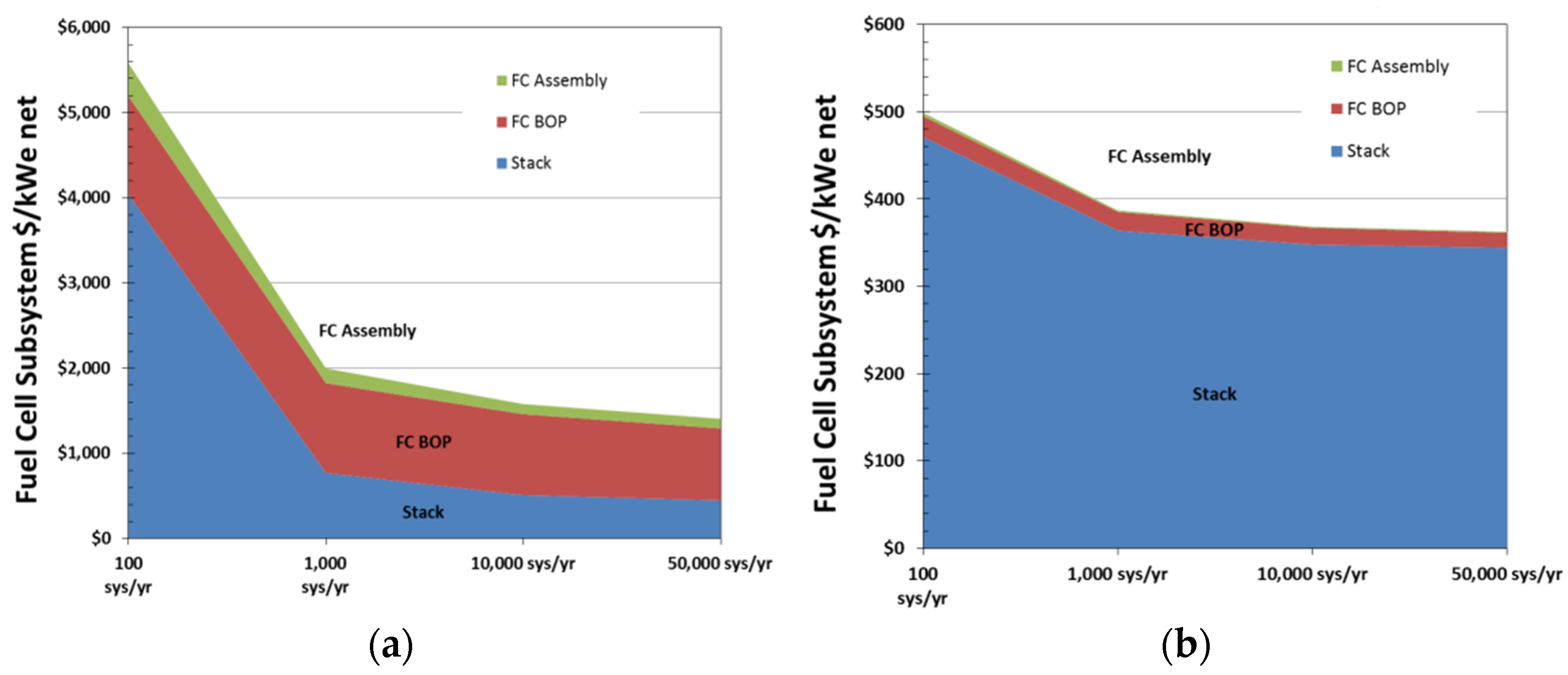
There are three routes for ammonia utilisation as the vehicular energy source. Firstly, ammonia acts as a hydrogen carrier. It is used by fuel cells after decomposition to release H2. Huge amounts of energy are required during ammonia decomposition, 2.79 kJ/mol-H2, theoretically. After decomposition, H2 separation, purification, storage, and compression are needed before it can be used by fuel cells [87]. Numerous catalysts are being developed and tested to optimise its decomposition process, which is the research hotspot for this route now. The comprehensive energy efficiency, including its production, transportation, and utilisation, is about 34%. Direct combustion is another method under the spotlight. NH3 can be mixed with other fuels, such as hydrogen, in certain proportions to enhance its combustion ability [92]. Ammonia internal combustion engines are successfully used in marine engineering and have proved to be feasible. After taking optimisation measures, its well-to-wheel energy utilisation efficiency of direct combustion can reach about 34%. The major pollutant in the combustion process is NOx. It can be reduced but cannot be completely avoided with the existing technology. Additionally, ammonia-fed solid-oxide fuel cell (SOFC) is an emerging technology which can directly use NH3 without decomposition. Two types of ammonia-fed SOFCs are developed, SOFC-H (proton-conducting) and SOFC-O (oxygen-ion conducting) [93]. SOFC-H may be the more suitable one for onboard use because of its higher energy utilisation efficiency considering the fuel economics. Its total energy efficiency is predicted to reach 46%. Among the three routes, direct use by fuel cell seems to have the best energy utilisation efficiency at 46%, approximately. The noteworthy hindrance to this route is the price of SOFCs, as shown in Figure 9. According to the analysis from B.D. James [94], the cost of a SOFC system is still at a high value, but will drop when higher powered systems and more SOFC systems are required. It can be predicted that the price of SOFC systems will continue to decrease with relevant technology improvement.
Although ammonia encourages relatively high energy consumption in both synthesis and decomposition (if required), it still has the highest overall well-to-wheel energy efficiency. From the point of view of fuel cost, ammonia shows the lowest price, regardless of direct use or decomposing, JPY 31 (USD 0.246) *Nm−3-H2 and JPY 24.5 (USD 0.201) *Nm−3-H2 in 2030, respectively [79]. Considering its high energy capacity, low cost, and mature supply chain, ammonia is, at least, a potential medium for hydrogen transportation. Moreover, it can be a promising candidate for locomotives with the technology development of its catalyst for decomposition and SOFC-H.

7. Metal Hydride-Based Storage

Metal hydride (MH)-based hydrogen storage technology is a chemical storage method where hydrogen is chemically stored on materials by an absorption process. Researchers from Romania [95] proposed a hybrid propulsion train with hydrogen stored in metal hydrides, which were made up of two locomotives and two wagons. Compared with battery packs, the metallic hydride tank can store five times more energy using the same weight. Additionally, it was declared to contain more energy per cubic meter than liquid hydrogen storage. Meanwhile, there are some researchers discussing the application of MH for light-duty mobile applications, such as forklifts and cars [96,97]. Thus, MH is another onboard hydrogen storage technology receiving attention.
MH storage systems are composed of the MH tubes. DOE uses Type III and IV tank technology for tube manufacturing, with stainless steel tubes also being used by some manufacturers. The fundamental performance of the MH system is determined by the material powder selected. At present, the main alloying materials for metal hydrides are intermetallic compounds (AB5, AB2, AB, and A2B). They are attractive as they are capable of absorbing large quantities of hydrogen. However, the hydrogen gravimetric density of common intermetallic metal hydrides is relatively low, as shown in Table 8, which is a serious impediment to their vehicular application. Moreover, their slow kinetics and complicated activation procedure further limit their practicality for mobile vehicles. Instead, intermetallic hydrides are applied to many other areas, such as nickel metal hydride battery electrodes, hydrogen purification systems, cooling systems, as well as hydrogen sensors [98].
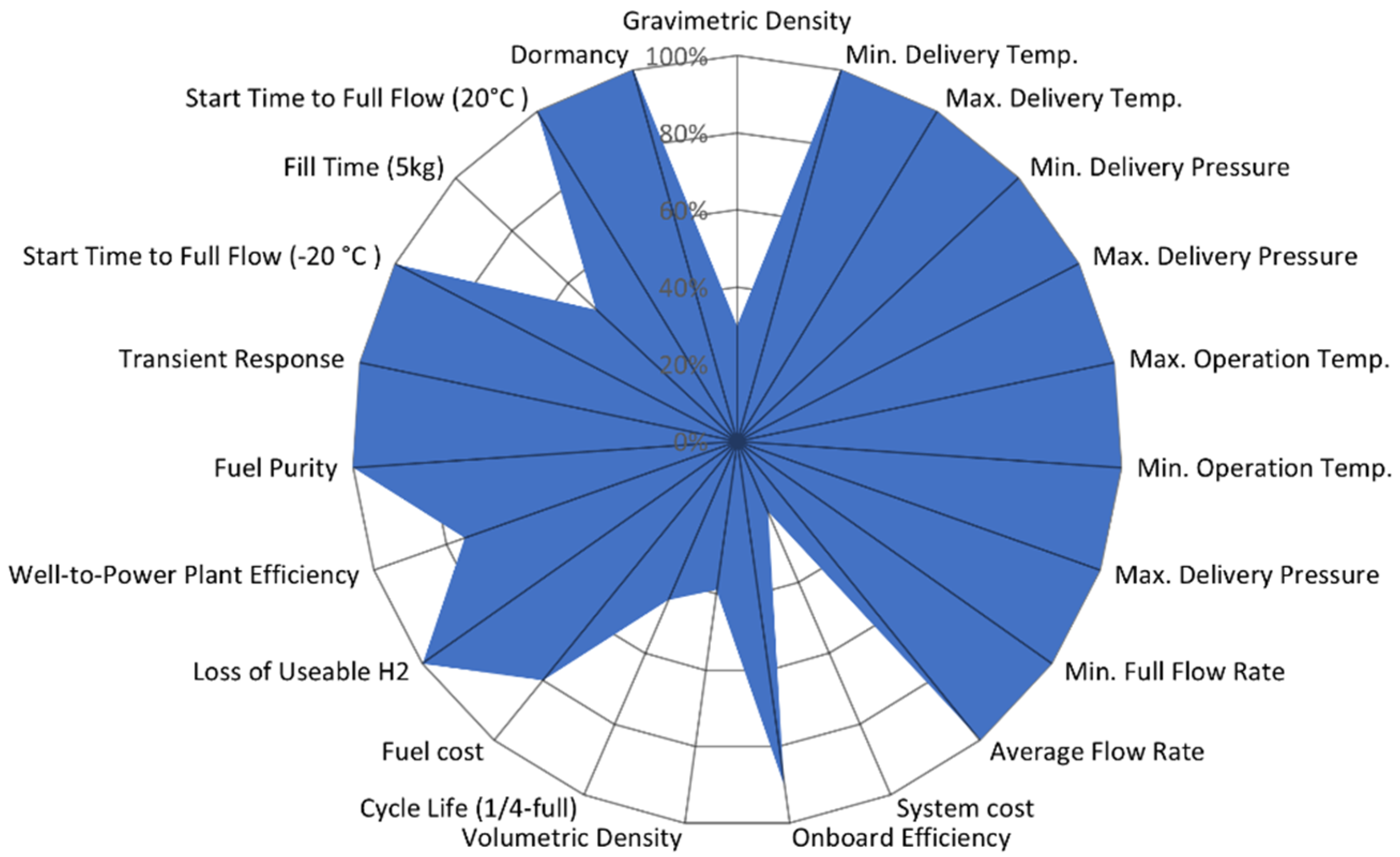
To enlarge hydrogen gravimetric capacity, complex hydrides composed of light elements gained significance. Challenges for its onboard utilisation mainly focus on the cost, operation conditions, and refuelling time. High thermodynamic stability and slow kinetics during hydrogen cycling affect its practicality in onboard use, causing high temperature and pressure to be essential during operation. Taking NaAlH4 (Sodium Alanate) as an example, its hydrogen storage capacity ranges from 2 wt% to 7 wt%, but its operation conditions are really harsh. High pressure and temperature are a must no matter what elements are added. It is demonstrated by DOE as shown in Figure 10 that the projected SAH system is inferior in terms of the system cost, fill time, and hydrogen storage density. Hopefully, these issues are being studied and tackled by the addition of new elements into the system, or the addition of reactive hydride composites. Overall, complex hydrides have higher H2 capacity than intermetallic hydrides. Further research on the novel material and optimisation for onboard thermal management systems is needed to improve its dehydrogenation and hydrogenation process before its practical application for locomotives.
Similarly, magnesium-based alloys have advantages in their hydrogen gravimetric capacity, up to 7.6 wt% [106]. Its hydrogenation and dehydrogenation process would be difficult due to the strong bonding between magnesium and hydrogen. Recent research shows that its hydrogen absorption/desorption properties can be enhanced at 573 K by the synthesis of ultra-fine microstructures and the addition of catalysts such as transition metals, rare earth metals, and transition metal oxides [26]. However, the kinetics of Mg-based hydrides are still unsatisfactory at low temperatures. Harsh operating/refuelling conditions and slow hydrogen supply rate are obstacles to their further onboard application.
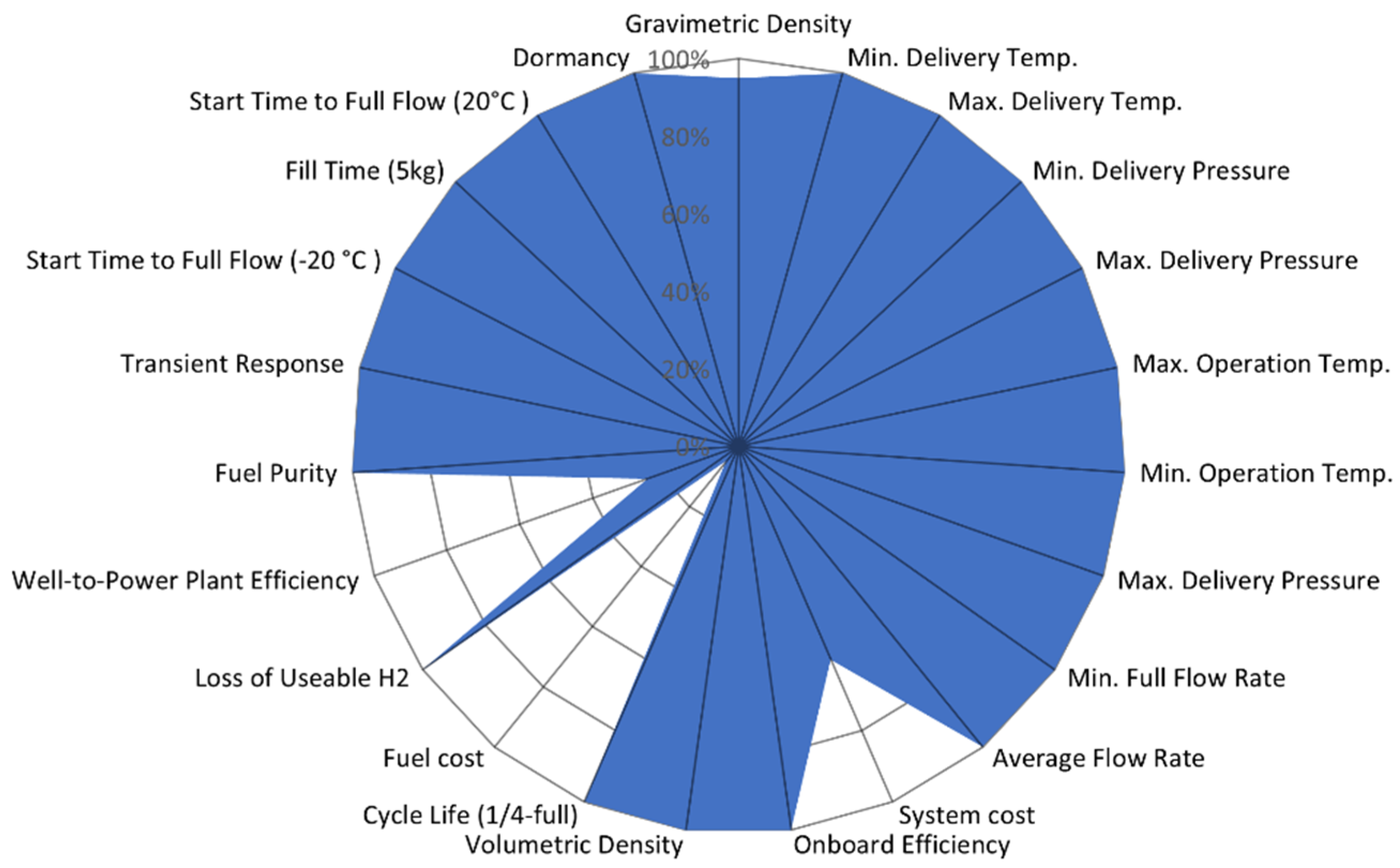
Chemical hydrides, such as ammonia borane (NH3BH3), raised considerable attention for their high gravimetric hydrogen storage capacities [107]. The published assessment on the ammonia borane system from DOE is presented in the form of a spider diagram, as shown in Figure 11. It can be easily seen that the system cost, well-to-power plant efficiency, and fuel cost are far from satisfactory. The barrier of most chemical hydrides for onboard application is their irreversibility, which makes them one-way single-use fuels. Moreover, leftover by-products must be removed from the vehicle for off-board regeneration. Therefore, chemical hydrides are not suitable for vehicle-mounted employment now, but they have great potential for hydrogen transportation as the H2 carrier.

8. Overall Comparison

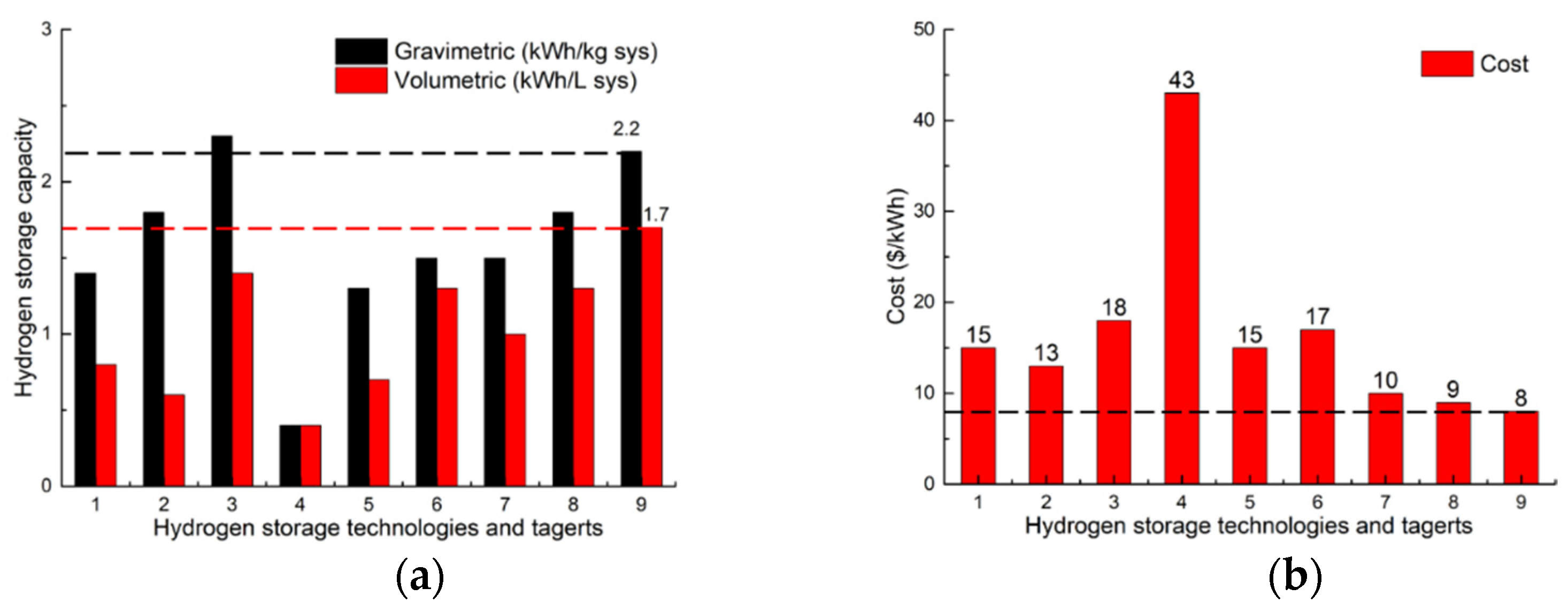
Since most hydrogen storage technologies are not commercially mature, there are not enough reliable industrial data to reflect their performance in practice. We used the data from DOE, ANL, LLNL, etc., which was published from 2013 to 2017 [108,109,110,111], to compare their storage capacity and cost, as shown in Figure 12. The selection of the hydrogen storage mode for trains requires a comprehensive consideration of their technical credibility and economic credibility according the specific requirements.
According to the published research reports from DOE, the barriers for the onboard potential hydrogen storage system are concluded and presented in Table 9. These problems need to be solved to improve their commercial maturity before it can be adopted and mounted on hydrogen-powered hybrid trains.
Integrating all the data and discussions from chapter 2 to chapter 8, the comprehensive summary of the potential storage methods is presented in Table 10. Meanwhile, their technology readiness level (TRL) is predicted based on the reports and research papers above.
Compressed gas hydrogen storage technology is widely used now. Most of the recently released hydrogen-powered locomotives are equipped with 35 MPa CH2 vessels. However, the hydrogen density still needs to be improved, so it has to be implemented in multi-groups to enlarge the operation range of the locomotives. Such a solution increases the complexity of the pipelines and requires much space occupation and costs. Therefore, CH2 storage technology may not be suitable for all types of railway systems, especially for long-haul freight trains. Liquid hydrogen storage technology overcomes the problems of H2 storage capacity to some extent. However, regional LH2 supply stations, filling supporting facilities, the safety system, etc., need to be further studied and implemented. Cryo-compressed hydrogen technology combines the high H2 storage capacity from LH2 and the long dormancy time from CH2. If only considering technical advantages, cryo-compressed hydrogen has the potential to be the next-generation onboard energy source for locomotives. Nonetheless, it is still in the prototype stage and there is a long way to go before large-scale commercial use.
Liquid organic hydrogen carrier technology is very attractive because of the high hydrogen storage capacity and low cost. Once the problems of its complex and slow dehydrogenation process are solved, it can be another candidate for the locomotive energy source. Additionally, metal hydrides technology is restricted by relatively harsh operating and refuelling conditions. The high cost for MH materials is another barrier for its commercialisation. Solving the issues above is the precondition of implementing hydride technology for railway transit. Ammonia is another promising hydrogen carrier for trains, since it has a high hydrogen capacity and low cost. With the storage safety and direct ammonia-fed SOFC technology being further evolved in the future, it is possible that ammonia will have a more important status in railway engineering.
To summarise, different hydrogen storage technologies have different benefits, which means they can adapt to varied requirements from different application scenarios. Several conclusions and suggestions can be drawn for railway transit:
  • For physical hydrogen storage technologies, it can be forecasted that they will be the most popular onboard storage technology for trains in the next few years, since CH2 storage can mostly meet the demands for train operation and is the most mature now. If higher requirements in terms of operation range and train power are raised, especially for long-haul freight trains, more attention should be paid to LH2 and CcH2 because of their high hydrogen storage capacities and relatively simple procedures before H2 enters fuel cell stacks. Their supporting technologies are being studied and becoming mature.
  • For material-based storage technologies, they are attractive for being able to absorb or adsorb quantities of hydrogen. They are capable for hydrogen transport as hydrogen carriers. Impediments of their train-mounted application are the dehydrogenation and hydrogenation process because controlled energy flow and refuelling speed are important evaluative criteria for mobility. Onboard thermal management design would be an emphasis for a material-based storage system.
  • Notably, ammonia has an extremely high energy capacity, along with low cost and a mature production chain. It has various application approaches according to different scenarios, which gives flexible choice for NH3-based vehicles. It has the viability to become the energy source for locomotives with relevant technological advances, especially the catalyst for decomposition and SOFC technology.

9. Conclusions

Several hydrogen storage systems with different principles have been developed, tested, and compared. They present different characteristics while being applied to industry applications. As locomotives are expected to work in heavy-duty conditions for a long period, the energy source should achieve high energy density, long term storage, and low cost.
In this paper, we collect the relevant data to compare the potential onboard hydrogen storage methods in terms of their hydrogen storage capacity, operational conditions, economic costs, etc. An overall comparison is conducted to show the advantages and disadvantages of the promising storage methods. Moreover, existing barriers for these storage systems are also presented. Based on the analysis, the conclusions and predictions are made to help readers figure out the technology readiness levels and future trends. It might be a reference for railway manufacturers to choose onboard hydrogen storage technology for their hydrogen-powered hybrid locomotives.
In our future study, we will continue to track the technical progress of onboard hydrogen storage technologies, especially their specific application for railway engineering. Moreover, more attention will be paid to the development of the supporting infrastructures, since they are the basis for the large-scale application of hydrogen energy. Suitability between the infrastructures and onboard storage system will be an essential evaluation criterion for the selection of an onboard hydrogen storage method. Furthermore, the Well-to-Tank efficiency and carbon emissions of the whole supply chain will be another focus to help evaluate their environmental friendliness. It is planned to conduct a comprehensive evaluation for train-used hydrogen storage technology considering economics, technical performance, and environmental requirements.

Author Contributions

Methodology, validation, data curation, and writing-original draft preparation, Z.X.; resources, review, and editing, N.Z. and Y.Y.; conceptualisation and investigation, S.H. and C.R. All authors have read and agreed to the published version of the manuscript.

Funding

This research was jointly supported by the UK Research and Innovation and DTE Network+ (reference 522620).

Institutional Review Board Statement

Not applicable.

Informed Consent Statement

Not applicable.

Data Availability Statement

Not applicable.

Acknowledgments

The first author thanks the financial support from the China Scholarship Council for his study at the University of Birmingham.

Conflicts of Interest

The authors declare no conflict of interest.

References

  1. Geels, F.W.; Sovacool, B.K.; Schwanen, T.; Sorrell, S. Sociotechnical transitions for deep decarbonization. Science 2017, 357, 1242–1244. [Google Scholar] [CrossRef] [PubMed]
  2. Pan, X.; Wang, H.; Wang, L.; Chen, W. Decarbonization of China’s transportation sector: In light of national mitigation toward the Paris Agreement goals. Energy 2018, 155, 853–864. [Google Scholar] [CrossRef]
  3. Cullen, D.A.; Neyerlin, K.C.; Ahluwalia, R.K.; Mukundan, R.; More, K.L.; Borup, R.L.; Weber, A.Z.; Myers, D.J.; Kusoglu, A. New roads and challenges for fuel cells in heavy-duty transportation. Nat. Energy 2021, 6, 462–474. [Google Scholar] [CrossRef]
  4. Khosravi, A.; Koury, R.N.N.; Machado, L.; Pabon, J.J.G. Energy, exergy and economic analysis of a hybrid renewable energy with hydrogen storage system. Energy 2018, 148, 1087–1102. [Google Scholar] [CrossRef]
  5. Atteridge, W.J.; Lloyd, S.A. Thoughts on use of hydrogen to power railway trains. Proc. Inst. Mech. Eng. Part A J. Power Energy 2021, 235, 306–316. [Google Scholar] [CrossRef]
  6. Hoffrichter, A.; Hillmansen, S.; Roberts, C. Conceptual propulsion system design for a hydrogen-powered regional train. IET Electr. Syst. Transp. 2016, 6, 56–66. [Google Scholar] [CrossRef]
  7. Jones, W.D. Hydrogen On Track. IEEE Spectr. 2006, 43, 10–13. [Google Scholar] [CrossRef]
  8. Washing, E.; Pulugurtha, S. Well-to-Wheel Analysis of Electric and Hydrogen Light Rail. J. Public Transp. 2015, 18, 74–88. [Google Scholar] [CrossRef]
  9. Gallas, D.; Stobnicki, P. Adoption of Modern Hydrogen Technologies in Rail Transport. J. Ecol. Eng. 2022, 23, 84–91. [Google Scholar] [CrossRef]
  10. Sun, Y.; Anwar, M.; Hassan, N.M.S.; Spiryagin, M.; Cole, C. A review of hydrogen technologies and engineering solutions for railway vehicle design and operations. Railw. Eng. Sci. 2021, 29, 212–232. [Google Scholar] [CrossRef]
  11. Miller, A.R.; Peters, J.; Smith, B.E.; Velev, O.A. Analysis of fuel cell hybrid locomotives. J. Power Sources 2006, 157, 855–861. [Google Scholar] [CrossRef]
  12. Hoffrichter, A.; Hillmansen, S.; Roberts, C. Review and assessment of hydrogen propelled railway vehicles. In Proceedings of the IET Conference on Railway Traction Systems, Birmingham, UK, 13–15 April 2010. [Google Scholar]
  13. Hoffrichter, A. Hydrogen-Rail (Hydrail) Development; H2@ Rail Workshop: Lansing, MI, USA, 2019; pp. 1–4.
  14. Yan, Y.; Li, Q.; Chen, W.; Su, B.; Liu, J.; Ma, L. Optimal energy management and control in multimode equivalent energy consumption of fuel cell/supercapacitor of hybrid electric tram. IEEE Trans. Ind. Electron. 2018, 66, 6065–6076. [Google Scholar] [CrossRef]
  15. Siwiec, J. Use of Hydrogen Fuel Cells in Rail Transport. Probl. Kolejnictwa 2021, 190, 113–117. [Google Scholar] [CrossRef]
  16. Calvert, C.; Allan, J.; Amor, P.; Hillmansen, S.; Roberts, C.; Weston, P. Concept development and testing of the UK’s first hydrogen-hybrid train (HydroFLEX). Railw. Eng. Sci. 2021, 29, 248–257. [Google Scholar] [CrossRef]
  17. Ogawa, K.; Yoneyama, T.; Sudo, T.; Kashiwagi, T.; Yamamoto, T. Performance improvement of fuel cell hybrid powered test railway vehicle. Q. Rep. RTRI 2021, 62, 16–21. [Google Scholar] [CrossRef]
  18. Durbin, D.J.; Malardier-Jugroot, C. Review of hydrogen storage techniques for on board vehicle applications. Int. J. Hydrogen Energy 2013, 38, 14595–14617. [Google Scholar] [CrossRef]
  19. Hassan, I.A.; Ramadan, H.S.; Saleh, M.A.; Hissel, D. Hydrogen storage technologies for stationary and mobile applications: Review, analysis and perspectives. Renew. Sustain. Energy Rev. 2021, 149, 111311. [Google Scholar] [CrossRef]
  20. Lahnaoui, A.; Wulf, C.; Heinrichs, H.; Dalmazzone, D. Optimizing hydrogen transportation system for mobility via compressed hydrogen trucks. Int. J. Hydrogen Energy 2019, 44, 19302–19312. [Google Scholar] [CrossRef]
  21. Abe, J.O.; Popoola, A.P.I.; Ajenifuja, E.; Popoola, O.M. Hydrogen energy, economy and storage: Review and recommendation. Int. J. Hydrogen Energy 2019, 44, 15072–15086. [Google Scholar] [CrossRef]
  22. Kayfeci, M.; Keçebaş, A. Hydrogen storage. In Solar Hydrogen Production; Elsevier: Amsterdam, The Netherlands, 2019; pp. 85–110. [Google Scholar]
  23. Xu, X.; Xu, H.; Zheng, J.; Chen, L.; Wang, J. A high-efficiency liquid hydrogen storage system cooled by a fuel-cell-driven refrigerator for hydrogen combustion heat recovery. Energy Convers. Manag. 2020, 226, 113496. [Google Scholar] [CrossRef]
  24. Ahluwalia, R.K.; Peng, J.K.; Roh, H.S.; Hua, T.Q.; Houchins, C.; James, B.D. Supercritical cryo-compressed hydrogen storage for fuel cell electric buses. Int. J. Hydrogen Energy 2018, 43, 10215–10231. [Google Scholar] [CrossRef]
  25. James, B.D.; Houchins, C.; Huya-Kouadio, J.M.; DeSantis, D.A. Hydrogen Storage System Cost Analysis; Strategic Analysis Inc.: Arlington, VA, USA, 2016. [Google Scholar]
  26. Rusman, N.A.A.; Dahari, M. A review on the current progress of metal hydrides material for solid-state hydrogen storage applications. Int. J. Hydrogen Energy 2016, 41, 12108–12126. [Google Scholar] [CrossRef]
  27. Ley, M.B.; Jepsen, L.H.; Lee, Y.-S.; Cho, Y.W.; Von Colbe, J.M.B.; Dornheim, M.; Rokni, M.; Jensen, J.O.; Sloth, M.; Filinchuk, Y. Complex hydrides for hydrogen storage–new perspectives. Mater. Today 2014, 17, 122–128. [Google Scholar] [CrossRef]
  28. Ponthieu, M.; Fernández, J.; Cuevas, F.; Bodega, J.; Ares, J.R.; Adeva, P.; Sánchez, C. Thermodynamics and reaction pathways of hydrogen sorption in Mg6 (Pd, TM)(TM = Ag, Cu and Ni) pseudo-binary compounds. Int. J. Hydrogen Energy 2014, 39, 18291–18301. [Google Scholar] [CrossRef]
  29. Liu, T.; Wang, C.; Wu, Y. Mg-based nanocomposites with improved hydrogen storage performances. Int. J. Hydrogen Energy 2014, 39, 14262–14274. [Google Scholar] [CrossRef]
  30. Smythe, N.C.; Gordon, J.C. Ammonia borane as a hydrogen carrier: Dehydrogenation and regeneration. Eur. J. Inorg. Chem. 2010, 2010, 509–521. [Google Scholar] [CrossRef]
  31. Macfarlane, D.R.; Cherepanov, P.V.; Choi, J.; Suryanto, B.H.R.; Hodgetts, R.Y.; Bakker, J.M.; Ferrero Vallana, F.M.; Simonov, A.N. A Roadmap to the Ammonia Economy. Joule 2020, 4, 1186–1205. [Google Scholar] [CrossRef]
  32. Alagharu, V.; Palanki, S.; West, K.N. Analysis of ammonia decomposition reactor to generate hydrogen for fuel cell applications. J. Power Sources 2010, 195, 829–833. [Google Scholar] [CrossRef]
  33. Davoodabadi, A.; Mahmoudi, A.; Ghasemi, H. The potential of hydrogen hydrate as a future hydrogen storage medium. Iscience 2021, 24, 101907. [Google Scholar] [CrossRef]
  34. USDoE. Hydrogen Sorption Center of Excellence (HSCoE) Final Report. Available online: https://www.energy.gov/eere/fuelcells/downloads/hydrogen-sorption-center-excellence-hscoe-final-report (accessed on 7 March 2014).
  35. Xia, Y.; Yang, Z.; Zhu, Y. Porous carbon-based materials for hydrogen storage: Advancement and challenges. J. Mater. Chem. A 2013, 1, 9365. [Google Scholar] [CrossRef]
  36. Ramirez-Vidal, P.; Sdanghi, G.; Celzard, A.; Fierro, V. High hydrogen release by cryo-adsorption and compression on porous materials. Int. J. Hydrogen Energy 2022, 47, 8892–8915. [Google Scholar] [CrossRef]
  37. Ahluwalia, R.; Peng, J. Automotive hydrogen storage system using cryo-adsorption on activated carbon. Int. J. Hydrogen Energy 2009, 34, 5476–5487. [Google Scholar] [CrossRef]
  38. Stamatakis, E.; Zoulias, E.; Tzamalis, G.; Massina, Z.; Analytis, V.; Christodoulou, C.; Stubos, A. Metal hydride hydrogen compressors: Current developments & early markets. Renew. Energy 2018, 127, 850–862. [Google Scholar]
  39. Tarasov, B.P.; Fursikov, P.V.; Volodin, A.A.; Bocharnikov, M.S.; Shimkus, Y.Y.; Kashin, A.M.; Yartys, V.A.; Chidziva, S.; Pasupathi, S.; Lototskyy, M.V. Metal hydride hydrogen storage and compression systems for energy storage technologies. Int. J. Hydrogen Energy 2021, 46, 13647–13657. [Google Scholar] [CrossRef]
  40. Rivard, E.; Trudeau, M.; Zaghib, K. Hydrogen Storage for Mobility: A Review. Materials 2019, 12, 1973. [Google Scholar] [CrossRef]
  41. Li, M.; Bai, Y.; Zhang, C.; Song, Y.; Jiang, S.; Grouset, D.; Zhang, M. Review on the research of hydrogen storage system fast refueling in fuel cell vehicle. Int. J. Hydrogen Energy 2019, 44, 10677–10693. [Google Scholar] [CrossRef]
  42. Hua, T.Q.; Ahluwalia, R.K.; Peng, J.K.; Kromer, M.; Lasher, S.; McKenney, K.; Law, K.; Sinha, J. Technical assessment of compressed hydrogen storage tank systems for automotive applications. Int. J. Hydrogen Energy 2011, 36, 3037–3049. [Google Scholar] [CrossRef]
  43. USDoE. DOE Technical Targets for Onboard Hydrogen Storage for Light-Duty Vehicles. Available online: https://www.energy.gov/eere/fuelcells/doe-technical-targets-onboard-hydrogen-storage-light-duty-vehicles (accessed on 1 November 2021).
  44. James, B.D.; Houchins, C. 700 Bar Type IV H2 Pressure Vessel Cost Projections. Available online: https://www.energy.gov/sites/prod/files/2016/09/f33/fcto_h2_storage_700bar_workshop_2_james.pdf (accessed on 24 August 2016).
  45. Din, T.; Hillmansen, S. Energy consumption and carbon dioxide emissions analysis for a concept design of a hydrogen hybrid railway vehicle. IET Electr. Syst. Transp. 2018, 8, 112–121. [Google Scholar] [CrossRef]
  46. Gallucci, M. Hydrogen trains roll into service: A new hybrid locomotive signals a growing push for zero-emission rail technologies—[News]. IEEE Spectr. 2019, 56, 6–7. [Google Scholar] [CrossRef]
  47. Ku, B.-Y. September 2021 Land Transportation News [Transportation Systems]. IEEE Veh. Technol. Mag. 2021, 16, 14–17. [Google Scholar] [CrossRef]
  48. Fedele, E.; Iannuzzi, D.; Del Pizzo, A. Onboard energy storage in rail transport: Review of real applications and techno-economic assessments. IET Electr. Syst. Transp. 2021, 11, 279–309. [Google Scholar] [CrossRef]
  49. Alstom. Successful Year and a Half of Trial Operation of the World’s First Two Hydrogen Trains, Next Project Phase Begins. Available online: https://www.alstom.com/press-releases-news/2020/5/successful-year-andhalf-trial-operation-worlds-first-two-hydrogen (accessed on 19 May 2020).
  50. Stetson, N.T.; McWhorter, S.; Ahn, C.C. Compendium of Hydrogen Energy: Hydrogen Storage, Distribution and Infrastructure; Woodhead Publishing: Sawston, UK, 2015; Volume 2, pp. 3–25. [Google Scholar]
  51. Yanxing, Z.; Maoqiong, G.; Yuan, Z.; Xueqiang, D.; Jun, S. Thermodynamics analysis of hydrogen storage based on compressed gaseous hydrogen, liquid hydrogen and cryo-compressed hydrogen. Int. J. Hydrogen Energy 2019, 44, 16833–16840. [Google Scholar] [CrossRef]
  52. Ahluwalia, R.; Hua, T.; Peng, J.; Kumar, R. System level analysis of hydrogen storage options. In DOE Hydrogen Program Annual Review; DOE: Washington, DC, USA, 2010. [Google Scholar]
  53. Ahluwalia, R.; Hua, T.; Peng, J.; Kumar, R. System level analysis of hydrogen storage options. In DOE Hydrogen Program Annual Review; DOE: Washington, DC, USA, 2020. [Google Scholar]
  54. Aziz, M.; Oda, T.; Kashiwagi, T. Comparison of liquid hydrogen, methylcyclohexane and ammonia on energy efficiency and economy. Energy Procedia 2019, 158, 4086–4091. [Google Scholar] [CrossRef]
  55. Peng, J.K.; Ahluwalia, R.K. Enhanced dormancy due to para-to-ortho hydrogen conversion in insulated cryogenic pressure vessels for automotive applications. Int. J. Hydrogen Energy 2013, 38, 13664–13672. [Google Scholar]
  56. Agarwal, R.; Dondapati, R.S. Numerical investigation on hydrodynamic characteristics of two-phase flow with liquid hydrogen through cryogenic feed lines at terrestrial and microgravity. Appl. Therm. Eng. 2020, 173, 115240. [Google Scholar] [CrossRef]
  57. Thomas, J.M.; Edwards, P.P.; Dobson, P.J.; Owen, G.P. Decarbonising energy: The developing international activity in hydrogen technologies and fuel cells. J. Energy Chem. 2020, 51, 405–415. [Google Scholar] [CrossRef]
  58. Kang, D.; Yun, S.; Kim, B.-K. Review of the Liquid Hydrogen Storage Tank and Insulation System for the High-Power Locomotive. Energies 2022, 15, 4357. [Google Scholar] [CrossRef]
  59. Siebel, T. Pressure in the Hydrogen Tank. ATZ Worldw. 2021, 123, 8–13. [Google Scholar]
  60. Rao, A.G.; Yin, F.; Werij, H. Energy Transition in Aviation: The Role of Cryogenic Fuels. Aerospace 2020, 7, 181. [Google Scholar] [CrossRef]
  61. Gupta, R.K.; Basile, A.; Veziroglu, T.N. Compendium of Hydrogen Energy; Woodhead Publishing: Cambridge, UK, 2016; Volume 2. [Google Scholar]
  62. Barthélémy, H.; Weber, M.; Barbier, F. Hydrogen storage: Recent improvements and industrial perspectives. Int. J. Hydrogen Energy 2017, 42, 7254–7262. [Google Scholar] [CrossRef]
  63. Moreno-Blanco, J.; Petitpas, G.; Espinosa-Loza, F.; Elizalde-Blancas, F.; Martinez-Frias, J.; Aceves, S.M. The storage performance of automotive cryo-compressed hydrogen vessels. Int. J. Hydrogen Energy 2019, 44, 16841–16851. [Google Scholar] [CrossRef]
  64. Ahluwalia, R.K.; Hua, T.Q.; Peng, J.K.; Lasher, S.; McKenney, K.; Sinha, J.; Gardiner, M. Technical assessment of cryo-compressed hydrogen storage tank systems for automotive applications. Int. J. Hydrogen Energy 2010, 35, 4171–4184. [Google Scholar] [CrossRef]
  65. Shafiei, E.; Davidsdottir, B.; Leaver, J.; Stefansson, H.; Asgeirsson, E.I. Comparative analysis of hydrogen, biofuels and electricity transitional pathways to sustainable transport in a renewable-based energy system. Energy 2015, 83, 614–627. [Google Scholar] [CrossRef]
  66. Zhan, X.; Yan, Y.; Wei, W.; Dongke, S.; Zhonghua, N. Supply system of cryo-compressed hydrogen for fuel cell stacks on heavy duty trucks. Int. J. Hydrogen Energy 2020, 45, 12921–12931. [Google Scholar]
  67. Yan, Y.; Xu, Z.; Han, F.; Wang, Z.; Ni, Z. Energy control of providing cryo-compressed hydrogen for the heavy-duty trucks driving. Energy 2021, 242, 122817. [Google Scholar] [CrossRef]
  68. Chen, L.; Xiao, R.; Cheng, C.; Tian, G.; Chen, S.; Hou, Y. Thermodynamic analysis of the para-to-ortho hydrogen conversion in cryo-compressed hydrogen vessels for automotive applications. Int. J. Hydrogen Energy 2020, 45, 24928–24937. [Google Scholar] [CrossRef]
  69. Ahluwalia, R.K.; Papadias, D.; Peng, J.-K.; Krause, T. Total Cost of Ownership for Line Haul, Yard Switchers and Regional Passenger Locomotives –Preliminary Results. In Proceedings of the 2019 US DOE Hydrogen Program Annual Merit Review, Crystal City, VA, USA, 29 April–1 May 2019. [Google Scholar]
  70. Aceves, S.; Brunner, T. Hydrogen Storage Tests for Cryo-Compressed Vessels, CRADA No. TC02119.0; Lawrence Livermore National Lab.(LLNL): Livermore, CA, USA, 2021.
  71. Petitpas, G. 1,000+ Cycles of a 350 Bar Prototype Cryo-Compressed Pressure Vessel; Lawrence Livermore National Lab.(LLNL): Livermore, CA, USA, 2018.
  72. James, B.D.; Houchins, C.; Huya-Kouadio, J.; DeSantis, D. Hydrogen Storage Cost Analysis. In Proceedings of the US DOE Hydrogen and Fuel Cells Program Annual Merit Review, Washington, DC, USA, 13–15 June 2018. [Google Scholar]
  73. Geiling, J.; Steinberger, M.; Ortner, F.; Seyfried, R.; Nuß, A.; Uhrig, F.; Lange, C.; Öchsner, R.; Wasserscheid, P.; März, M.; et al. Combined dynamic operation of PEM fuel cell and continuous dehydrogenation of perhydro-dibenzyltoluene. Int. J. Hydrogen Energy 2021, 46, 35662–35677. [Google Scholar] [CrossRef]
  74. Rao, P.C.; Yoon, M. Potential liquid-organic hydrogen carrier (LOHC) systems: A review on recent progress. Energies 2020, 13, 6040. [Google Scholar] [CrossRef]
  75. Niermann, M.; Timmerberg, S.; Drünert, S.; Kaltschmitt, M. Liquid Organic Hydrogen Carriers and alternatives for international transport of renewable hydrogen. Renew. Sustain. Energy Rev. 2021, 135, 110171. [Google Scholar] [CrossRef]
  76. Preuster, P.; Papp, C.; Wasserscheid, P. Liquid organic hydrogen carriers (LOHCs): Toward a hydrogen-free hydrogen economy. Acc. Chem. Res. 2017, 50, 74–85. [Google Scholar] [CrossRef]
  77. Gonda, M.; Ohshima, M.A.; Kurokawa, H.; Miura, H. Toluene hydrogenation over Pd and Pt catalysts as a model hydrogen storage process using low grade hydrogen containing catalyst inhibitors. Int. J. Hydrogen Energy 2014, 39, 16339–16346. [Google Scholar] [CrossRef]
  78. Mizuno, Y.; Ishimoto, Y.; Sakai, S.; Sakata, K. Economic analysis on international hydrogen energy carrier supply chains. J. Jpn. Soc. Energy Resour. 2016, 38, 11–17. [Google Scholar]
  79. Wijayanta, A.T.; Oda, T.; Purnomo, C.W.; Kashiwagi, T.; Aziz, M. Liquid hydrogen, methylcyclohexane, and ammonia as potential hydrogen storage: Comparison review. Int. J. Hydrogen Energy 2019, 44, 15026–15044. [Google Scholar] [CrossRef]
  80. Hurskainen, M.; Ihonen, J. Techno-economic feasibility of road transport of hydrogen using liquid organic hydrogen carriers. Int. J. Hydrogen Energy 2020, 45, 32098–32112. [Google Scholar] [CrossRef]
  81. Aakko-Saksa, P.T.; Cook, C.; Kiviaho, J.; Repo, T. Liquid organic hydrogen carriers for transportation and storing of renewable energy—Review and discussion. J. Power Sources 2018, 396, 803–823. [Google Scholar] [CrossRef]
  82. Fikrt, A.; Brehmer, R.; Milella, V.-O.; Müller, K.; Bösmann, A.; Preuster, P.; Alt, N.; Schlücker, E.; Wasserscheid, P.; Arlt, W. Dynamic power supply by hydrogen bound to a liquid organic hydrogen carrier. Appl. Energy 2017, 194, 1–8. [Google Scholar] [CrossRef]
  83. Ezzat, M.; Dincer, I. Comparative assessments of two integrated systems with/without fuel cells utilizing liquefied ammonia as a fuel for vehicular applications. Int. J. Hydrogen Energy 2018, 43, 4597–4608. [Google Scholar] [CrossRef]
  84. Ezzat, M.; Dincer, I. Development and assessment of a new hybrid vehicle with ammonia and hydrogen. Appl. Energy 2018, 219, 226–239. [Google Scholar] [CrossRef]
  85. Al-Hamed, K.H.; Dincer, I. A novel ammonia solid oxide fuel cell-based powering system with on-board hydrogen production for clean locomotives. Energy 2021, 220, 119771. [Google Scholar] [CrossRef]
  86. Al-Hamed, K.H.; Dincer, I. Investigation of an integrated powering system for clean locomotives with solid-oxide fuel cell with heat recovery organic Rankine cycle. Energy Convers. Manag. 2020, 219, 112857. [Google Scholar] [CrossRef]
  87. Lamb, K.E.; Dolan, M.D.; Kennedy, D.F. Ammonia for hydrogen storage; A review of catalytic ammonia decomposition and hydrogen separation and purification. Int. J. Hydrogen Energy 2019, 44, 3580–3593. [Google Scholar] [CrossRef]
  88. Lan, R.; Irvine, J.T.; Tao, S. Ammonia and related chemicals as potential indirect hydrogen storage materials. Int. J. Hydrogen Energy 2012, 37, 1482–1494. [Google Scholar] [CrossRef]
  89. Ezzat, M.F.; Dincer, I. Energy and exergy analyses of a novel ammonia combined power plant operating with gas turbine and solid oxide fuel cell systems. Energy 2020, 194, 116750. [Google Scholar] [CrossRef]
  90. Barelli, L.; Bidini, G.; Cinti, G. Operation of a Solid Oxide Fuel Cell Based Power System with Ammonia as a Fuel: Experimental Test and System Design. Energies 2020, 13, 6173. [Google Scholar] [CrossRef]
  91. Valera-Medina, A.; Xiao, H.; Owen-Jones, M.; David, W.I.; Bowen, P. Ammonia for power. Prog. Energy Combust. Sci. 2018, 69, 63–102. [Google Scholar] [CrossRef]
  92. Chai, W.S.; Bao, Y.; Jin, P.; Tang, G.; Zhou, L. A review on ammonia, ammonia-hydrogen and ammonia-methane fuels. Renew. Sustain. Energy Rev. 2021, 147, 111254. [Google Scholar] [CrossRef]
  93. Afif, A.; Radenahmad, N.; Cheok, Q.; Shams, S.; Kim, J.H.; Azad, A.K. Ammonia-fed fuel cells: A comprehensive review. Renew. Sustain. Energy Rev. 2016, 60, 822–835. [Google Scholar] [CrossRef]
  94. James, B.D.; DeSantis, D.A. Manufacturing Cost and Installed Price Analysis of Stationary Fuel Cell Systems; Strategic Analysis Inc.: Arlington, VA, USA, 2015. [Google Scholar]
  95. Stanescu, A.; Mocioi, N.; Dimitrescu, A. Hybrid Propulsion Train with Energy Storage in Metal Hydrides. In Proceedings of the Electric Vehicles International Conference (EV), Bucharest, Romania, 3–4 October 2019; IEEE: Bucharest, Romania, 2019; pp. 1–4. [Google Scholar]
  96. Davids, M.; Lototskyy, M.; Malinowski, M.; Van Schalkwyk, D.; Parsons, A.; Pasupathi, S.; Swanepoel, D.; van Niekerk, T. Metal hydride hydrogen storage tank for light fuel cell vehicle. Int. J. Hydrogen Energy 2019, 44, 29263–29272. [Google Scholar] [CrossRef]
  97. Lototskyy, M.; Tolj, I.; Klochko, Y.; Davids, M.W.; Swanepoel, D.; Linkov, V. Metal hydride hydrogen storage tank for fuel cell utility vehicles. Int. J. Hydrogen Energy 2020, 45, 7958–7967. [Google Scholar] [CrossRef]
  98. Falahati, H.; Barz, D.P.J. Evaluation of hydrogen sorption models for AB5-type metal alloys by employing a gravimetric technique. Int. J. Hydrogen Energy 2013, 38, 8838–8851. [Google Scholar] [CrossRef]
  99. Szajek, A.; Jurczyk, M.; Okońska, I.; Smardz, K.; Jankowska, E.; Smardz, L. Electrochemical and electronic properties of nanocrystalline Mg-based hydrogen storage materials. J. Alloys Compd. 2007, 436, 345–350. [Google Scholar] [CrossRef]
  100. Wang, P.; Kang, X.-d. Hydrogen-rich boron-containing materials for hydrogen storage. Dalton Trans. 2008, 5400–5413. [Google Scholar] [CrossRef] [PubMed]
  101. Züttel, A.; Wenger, P.; Rentsch, S.; Sudan, P.; Mauron, P.; Emmenegger, C. LiBH4 a new hydrogen storage material. J. Power Sources 2003, 118, 1–7. [Google Scholar] [CrossRef]
  102. Gross, K.; Sandrock, G.; Thomas, G. Dynamic in situ X-ray diffraction of catalyzed alanates. J. Alloys Compd. 2002, 330, 691–695. [Google Scholar] [CrossRef]
  103. Jensen, C.; Gross, K. Development of catalytically enhanced sodium aluminum hydride as a hydrogen-storage material. Appl. Phys. A 2001, 72, 213–219. [Google Scholar] [CrossRef]
  104. Urbanczyk, R.; Peinecke, K.; Felderhoff, M.; Hauschild, K.; Kersten, W.; Peil, S.; Bathen, D. Aluminium alloy based hydrogen storage tank operated with sodium aluminium hexahydride Na3AlH6. Int. J. Hydrogen Energy 2014, 39, 17118–17128. [Google Scholar] [CrossRef]
  105. USDoE. System Projection Graphs. Available online: https://www.energy.gov/eere/fuelcells/hydrogen-storage-engineering-center-excellence#graphs (accessed on 8 March 2022).
  106. De Castro, J.F.R.; Santos, S.F.; Costa, A.L.M.; Yavari, A.R.; Botta F, W.J.; Ishikawa, T.T. Structural characterization and dehydrogenation behavior of Mg–5 at.%Nb nano-composite processed by reactive milling. J. Alloys Compd. 2004, 376, 251–256. [Google Scholar] [CrossRef]
  107. Kang, X.-D.; Luo, J.-H.; Wang, P. Efficient and highly rapid hydrogen release from ball-milled 3NH3BH3/MMgH3 (M = Na, K, Rb) mixtures at low temperatures. Int. J. Hydrogen Energy 2012, 37, 4259–4266. [Google Scholar] [CrossRef]
  108. USDoE. Hydrogen Storage Tech Team Roadmap. Available online: https://www.energy.gov/sites/prod/files/2017/08/f36/hstt_roadmap_July2017.pdf (accessed on 30 July 2017).
  109. USDoE. DOE Hydrogen and Fuel Cells Program Record#15013. Available online: https://www.hydrogen.energy.gov/pdfs/15013_onboard_storage_performance_cost.pdf (accessed on 30 September 2015).
  110. USDoE. System Level Analysis of Hydrogen Storage Options. Available online: https://www.hydrogen.energy.gov/pdfs/review17/st001_ahluwalia_2017_o.pdf (accessed on 5 June 2017).
  111. USDoE. Hydrogen Storage Engineering Center of Excellence-Savannah River National Laboratory (Anton). Available online: https://www.hydrogen.energy.gov/pdfs/review16/st004_anton_2016_o.pdf (accessed on 9 June 2016).
  112. USDoE. Department of Energy Hydrogen Program Plan. Available online: https://www.hydrogen.energy.gov/roadmaps_vision.html (accessed on 30 November 2020).
Figure 1. Cost breakdown for type IV 700 bar H2 single tank storage systems with 5.6 kg usable (from DOE): (a) 10 k systems per year; (b) 500 k systems per year [44].
Energies 15 06467 g001
Figure 2. Diagram of Coradia ilint train, Alstom, propulsion system [49].
Energies 15 06467 g002
Figure 3. Design of HydroFLEX’s pantograph motor open second (PMOS) carrier.
Energies 15 06467 g003
Figure 4. (a) Liquid hydrogen storage system from Linde [60]; (b) Schematic of the LH2-hybrid train and the charging infrastructure presented by KRRI.
Energies 15 06467 g004
Figure 5. Hydrogen density versus pressure and temperature from BMW. Reprinted/adapted with permission from Ref. [62], copyright 2017 Elsevier.
Energies 15 06467 g005
Figure 6. Onboard cryo-compressed hydrogen storage and supply system, LLNL. Reprinted/adapted with permission from Ref. [24], copyright 2018 Elsevier.
Energies 15 06467 g006
Figure 7. Schematic of CcH2 storage vessel from BMW.
Energies 15 06467 g007
Figure 8. Overall system costs (OSC) of the assessed hydrogen supply chains (DBT: dibenzyltoluene, HPT: high-pressure tank, HVDC: High Voltage Direct Transmission, LH2: Liquefied Hydrogen, LOHC: Liquid Organic Hydrogen Carrier, MET: methanol, NEC: N-ethylcarbazole, Pipe: Pipeline, TOL: toluene). Reprinted/adapted with permission from Ref. [75], copyright 2021 Elsevier.
Energies 15 06467 g008
Figure 9. Cost prediction and analysis for SOFC subsystem (a) 1 kWe Fuel Cell SOFC Subsystem; (b) 100 kWe Fuel Cell SOFC Subsystem [94].
Energies 15 06467 g009
Figure 10. Projected sodium alanate (SAH) system compared against 2020 targets, dual tank, from DOE [105].
Energies 15 06467 g010
Figure 11. Projected ammonia borane system compared against 2020 Targets, 50% mass loaded slurry, from DOE [105].
Energies 15 06467 g011
Figure 12. Projected performance of hydrogen storage systems (a) comparison of hydrogen storage capacity; (b) comparison of cost, projected to 500 k units/yr. (1:700 bar compressed Type IV; 2: 300 bar compressed Type IV; 3: 500 bar cryo-compressed; 4: metal hydrideNaAlH4/Ti; 5: Sorbent MOF-5100 bar; 6: Chemical storage, AB liquid; 7: 2020 target values; 8: 2025 target values; 9: ultimate target values).
Energies 15 06467 g012
Table 1. Different types of compressed gas hydrogen tanks [40,41].
TypeMaterialsFeaturesTypical Pressure (MPa)Cost (USD/kg)Gravimetric Density (wt%)
IAll-metal constructionHeavy, internal corrosion17.5–20831.7
IIAll-metal hoop-wrapped composite cylindersHeavy, short life due to internal corrosion20–30862.1
IIIFully wrapped composite cylinders with metallic linersLightness, high burst pressure, no permeation, galvanic corrosion between liner and fibre (CF)35–705675–5.5
IVAll-composite constructionLightness, lower burst pressure. High durability against repeated charging. Simple manufacturability35–706335–5.7
(Toyota data)
Table 2. Summary results of assessment for CH2 storage system compared to DOE targets [42,43].
Performance and
Cost Metric
Units35 MPa70 MPa2020
Targets
2025
Targets
Ultimate
System gravimetric capacityWt %5.55.24.55.56.5
System volumetric capacityg-H2/L17.626.3304050
Storage system costUSD/kWh15.418.71098
WTT efficiency (LHV)%56.554.2606060
Table 3. Recently revealed hydrogen-powered trains.
Hydrogen-Powered TrainsHydroFLEX 1.0
Energies 15 06467 i001
CRRC Datong
Energies 15 06467 i002
Coradia iLint
Energies 15 06467 i003
ManufacturerPorterbrook and University of Birmingham, UK, 2019CRRC, China, 2021Alstom, Germany, 2018
TypePassenger locomotiveFreight locomotivePassenger train
Hydrogen storage method35 MPa CH2 vessel35 MPa CH2 vessel35 MPa CH2 vessel
Fuel cellPEMFC (400 kW)PEMFC (400 kW)PEMFC
Auxiliary powerBattery (400 kW)Battery (1000 kW)Battery
Table 4. Cost comparison between CH2 and LH2 based on the specific scenarios (USD/kg) [53].
PathwayH2 ProductionStorage (Plant)LiquefactionTerminalTransmissionDistributionDispensing (LDV)Total Cost
CA(CH2)1.640.23-1.14-0.892.276.17
CA (LH2)1.64-2.860.31-0.301.947.05
TX to CA (LH2)0.890.312.150.331.100.301.947.02
Table 5. Storage system cost comparison between CH2, Cold-cH2, and CcH2 (USD/kWh).
350 Bar CcH2500 Bar CcH2700 Bar CcH2350 Bar CH2Cold-CH2
Liner1.031.010.990.211.58
Composite3.254.707.129.798.86
Insulation and containment vessel3.483.212.920.003.05
BOP3.843.853.853.253.45
Assembly and other0.040.040.040.120.04
System cost
(USD/kWh)
11.65
[−2.32, +2.90]
12.82
[−2.32, +2.90]
14.92
[−2.78, +3.61]
13.38
[−3.44, +5.73]
16.97
[−0.81, +1.59]
Table 6. Technical properties of some potential LOHCs [81].
PropertiesToluene-MCHNaphthalene-DecalinBenzene-CyclohexaneDBT-PDBT
TolueneMCHNaphthaleneDecalinBenzeneCyclohexaneDBTPDBT
Physical
Chemical formulaC7H8C7H14C10H8C10H18C6H6C6H12C21H20C21H38
density8670.7690.9750.8960.8740.7791.0101.057
Melting point−95−12780.3Cis −43.0
Trans −30.4
5.56.5−30−34
Boiling point111101218Cis −94.6
Trans 185.5
8081278395
Phase under ambient cond.LiquidLiquidSolidLiquidLiquidLiquidLiquidLiquid
Gravimetric density (wt%)6.167.297.26.2
Volumetric density(kg/m3)47.465.455.957
Heat of reaction (kJ/mol)204.8319.5(cis), 332.5(trans)205.9588.5
Temperature (°C)200–300150–250150–250180
Pressure (bar)10–5020–5010–5010–50
Dehydrogenation with selected catalyst
Temperature (°C)250–350300–350330260–320
Pressure (bar)1–51–41–41–5
AdvantagesBoth liquid in wide range temperature-Relatively high H2 content-Relatively high H2 content-Higher intrinsic safety
-Good thermal stability
Challenges-Irritative
inflammable
-Volatile
-Different phase (difficulties in storage and transportation)
-High energy for
dehydrogenation
-Volatile
-High melting point (possibility of phase change)
-Toxic
-High energy for dehydrogenation
Table 7. Relevant properties of ammonia [91].
PropertyUnitValue
Molecular weightg/mol7.03
Gravimetric H2 capacitywt%17.7
Volumetric H2 capacitykg-H2/m−3120.3
Storage conditionbar or K10 or 240
H2 release temperatureK600–1200
Regeneration temperatureK650–900
Ignition temperatureK924
PriceUSD/kg (USD/kWh)0.3 (0.058)
Table 8. Properties of some metal hydrides [99,100,101,102,103,104].
TypeComponentHydrogen Storage Capacity (wt%)Temperature (K)Pressure (MPa)
Intermetallic hydridesLaNi5H61.372950.1
FeTiH21.891850.1
Mg2NiH43.592550.1
ZrMn2H21.774400.1
Complex hydridesLiBH4 nanocomposite6.5573-
LiBH4 + SiO213.53735.0
NaAlH4 + 1.0 mol% TiCl35.6323–383-
NaAlH4 + 4.0 mol% Ti4.8373-
NaAlH4 + 1.0 mol% Ti5.6443/42315.4
Na3AlH6 + 2.0 mol% TiCl32.1473/5436.0
NaAlH4 + porous carbon7.067310.0
NaAlH4 + none-porous carbon6.367310.0
Table 9. Existing barriers for potential hydrogen storage systems [108,112].
Physical Storage SystemsMaterial-Based Storage System
BarriersCompressedCold/Cryo-CompressedMetal HydrideSorbent-BasedChemical Storage
Materials of Construction
Balance-of-Plant Cost
Thermal Management
Tank Cost
Tank Mass
Off-board Energy Efficiency
Heat Transfer Systems
Material Gravimetric Capacity
Material Volumetric Capacity
Reaction Thermodynamics
Cryogenic Tank Operation
High Temperature Tank Operation
Carbon Fibre Cost
Material Thermal Conductivity
Fuel Purity
Kinetics
Reactor Design
Material Handling
Table 10. Summary of different hydrogen storage technologies for onboard use.
Hydrogen Storage TechnologyAdvantagesDisadvantagesCurrent StateTRL
Physical Storage MethodsCompressed hydrogen-Relatively mature
-Many types of storage tanks for different areas
-Purity
-Storage density needs to be improved
-Cost needs to be reduced
-Successfully used for trains
-Mass production
8/9
Liquid hydrogen-High volumetric capacity
-Purity
-Relatively low utilisation cost
-High liquification cost
-Short dormancy time (boil-off)
-Mostly used for military and aerospace
-Prototype trucks
-Being tested for trains in KR and JP
6/7
Cryo-compressed hydrogen-High hydrogen capacity
-Long dormancy time
-Relatively low cost
-Low maturity-Prototype cars
-Onboard simulation for trains by DOE
4/5
Material-based (chemical) storage methodsMetal hydrides-Some types have high storage capacity
-Able to absorb large quantities of hydrogen
-Multi-role
-Harsh operation conditions
-Refuelling time
-High cost for onboard use
-Prototype vehicles
-Mostly discussed for hydrogen transportation
4/5
Liquid organic hydrogen carriers (LOHC)-High hydrogen capacity
-Relatively low cost
-Complex catalytic conditions
-Low hydrogen releasing speed
-Toxic by-product
-Unavoidable purification
-Being tested for trains by Siemens
-Mostly discussed for hydrogen transportation
6/7
Ammonia-Mature production chain
-Low cost
-Multiple use routes
-By-product NOx
-Toxic
-Expensive DA-SOFC
-Dehydrogenation cost
-Successfully used for marine applications (direct combustion)
-Lab stage (SOFC route)
6/7 (direct combustion)
4/5 (SOFC route)
Publisher’s Note: MDPI stays neutral with regard to jurisdictional claims in published maps and institutional affiliations.