2. Examples of More Complex Objective Functions and Constraints Used in Previous Research
The aim of formulating the coordination of overcurrent relays as an optimization problem is to minimize the operating time of primary and backup relays, respectively [
2,
3]. In any power system, the problem of coordinating primary and backup relays consists of correct determination of their settings, such that their protective function is met under the right requirements, such as selectivity, sensitivity, speed and reliability. Due to the reason that the relay pairs (primary and backup) should be coordinated together, and considering different network topologies in the coordination problem, coordination constraints corresponding to each relay pair (miscoordination problem) should be added to the optimization problem [
4].
This chapter gives an overview of the more complex objective functions used to solve the protection coordination optimization problem. In the existing studies, various approaches based on the genetic algorithm (GA) have been proposed to improve the problem formulation in order to achieve relay protection coordination and optimum relay operation time, in addition to minimizing the number of coordination constraints. GA is a computerized search and optimization algorithm based on the mechanics of the evolution theory. It is an adaptive method commonly used to solve or search for the near-to best value in an optimization problem. By imitating the theory of evolution, genetic algorithms are based on genetic processes occurring through many generations in a natural population. In every iteration of the optimization algorithm, the population improves if the rules are met, obtaining an individual or group of individuals which satisfy the given constraints, and this individual or group of individuals will eventually approach the optimal solution [
5].
Well-formulated objective function (OF) is of great importance in the optimization process. Objective function, which is already used in most of the literature, is given in [
6,
7,
8,
9]:
where
is the number of relays,
is the operating time of relay
and
is the weight assigned to each relay.
A nonlinear inverse OCR characteristic function, which has been reported in most of the previously mentioned literature, is shown in Equation (2) [
10,
11,
12]:
where
,
, and
are constants chosen to provide the selected curve characteristics,
is the actual fault current,
(plug setting) is the relay current set point and
is the time multiplier setting of the relay
.
In order to obtain a reasonable and optimal coordination with suitable operation time for the relays, the constraints that limit the objective function given in Equation (1) must be considered. These constraints can stand separately, and in the case that they are breached, the optimization solution (relay settings of the entire network) is discarded, or they can be added as a penalty value to the objective function.
The coordination constraint between the main and backup relay can be expressed as follows [
13,
14,
15]:
where
and
are the operating time of the backup relay and the primary relay, respectively.
is the abbreviation of “coordination time interval”. Roughly speaking,
mostly consists of CB operating time, which is measured from the moment the CB received a trip signal from the relay until the moment its contacts are opened (and the current stops flowing through the CB) [
16,
17].
As stated in most of the previous research literature, basic objective function has three main drawbacks. First, two are concerned with miscoordination, meaning that the operation time of backup relays is either less than that of the main relays (albeit this occurs in rare instances in practical cases), or the coordination time interval between two consecutive relays is breached, and the relays trip their respective CBs simultaneously (this situation occurs more often). The third drawback is the opposite from the previous cases, and it regards the inability to avoid large discrimination times in addition to the coordination time interval between a primary and backup relay. This simply means that a backup relay will react too slow. To avoid the aforementioned drawbacks, basic OF1 was modified in numerous ways by many authors.
Modified OF was presented in [
18,
19,
20,
21,
22], and it has cleared the miscoordination problem of the previous methods:
OF2 has two terms. The first term is the operating time of the overcurrent relay, and the minimum of this term is reached when the relay operates in the shortest possible time. The second term is the penalty term. The penalty term considers coordination constraint
, which represents the time difference between
j-th P/B relay pairs including
. This is actually the coordination constraint in Equation (3), but rewritten in terms of discrimination time
.
and
are the operating times of the P/B relays,
is the number of P/B relay pairs, and
represents each P/B relay pair and varies from 1 to
.
is the coordination time interval,
is used to control the weighting of
, and
is used to control the weighting of
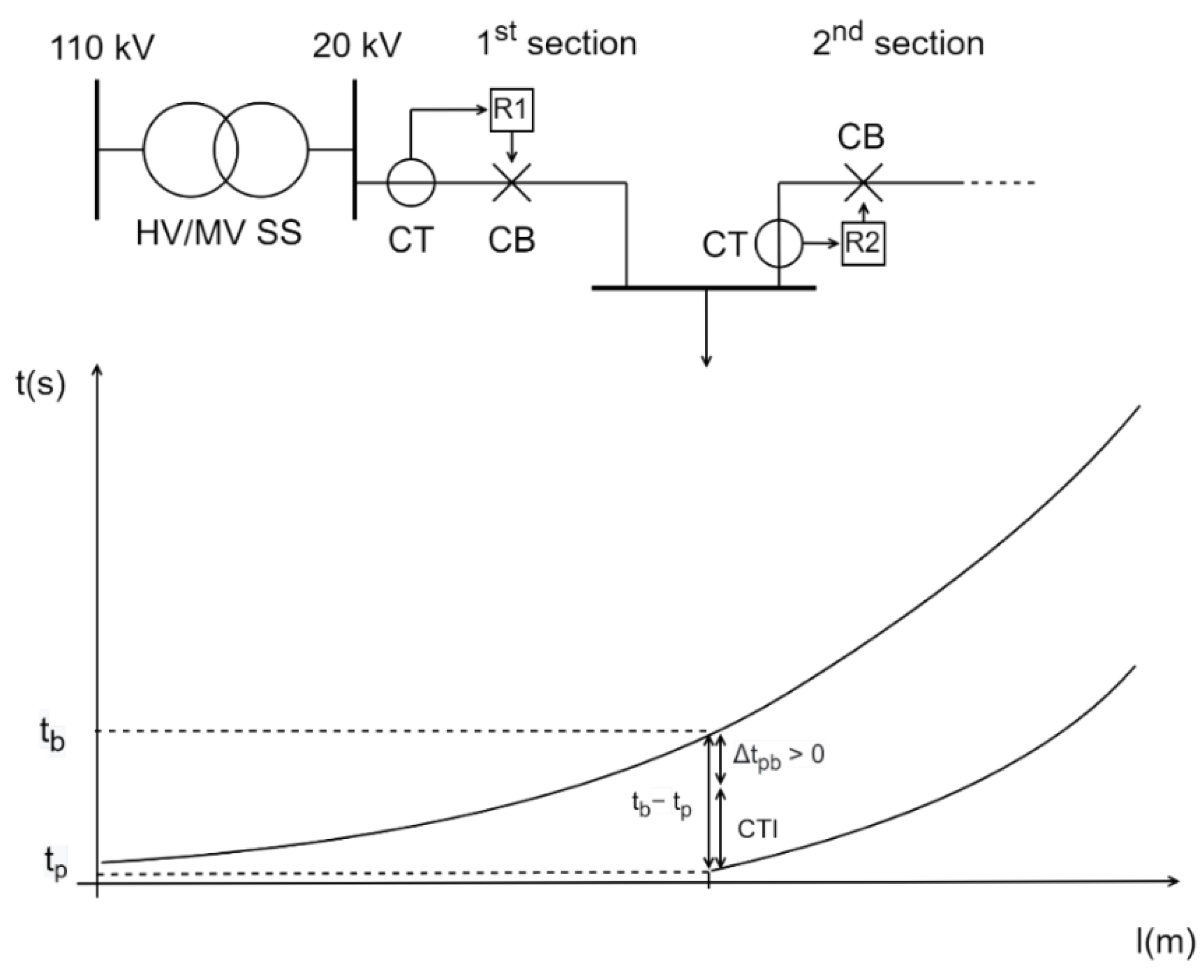
. The basic idea behind this optimization function is to simply minimize
along with the primary relays’ operating time, which is denoted in
Figure 1.
This means that the sum of the relay operating times of all relays in the network will be minimized for the cases where no relay fails to operate, but additionally this also encompasses all cases where relays indeed fail to operate and their backup relays take over. This is ensured by minimizing the second part in the objective function OF2.
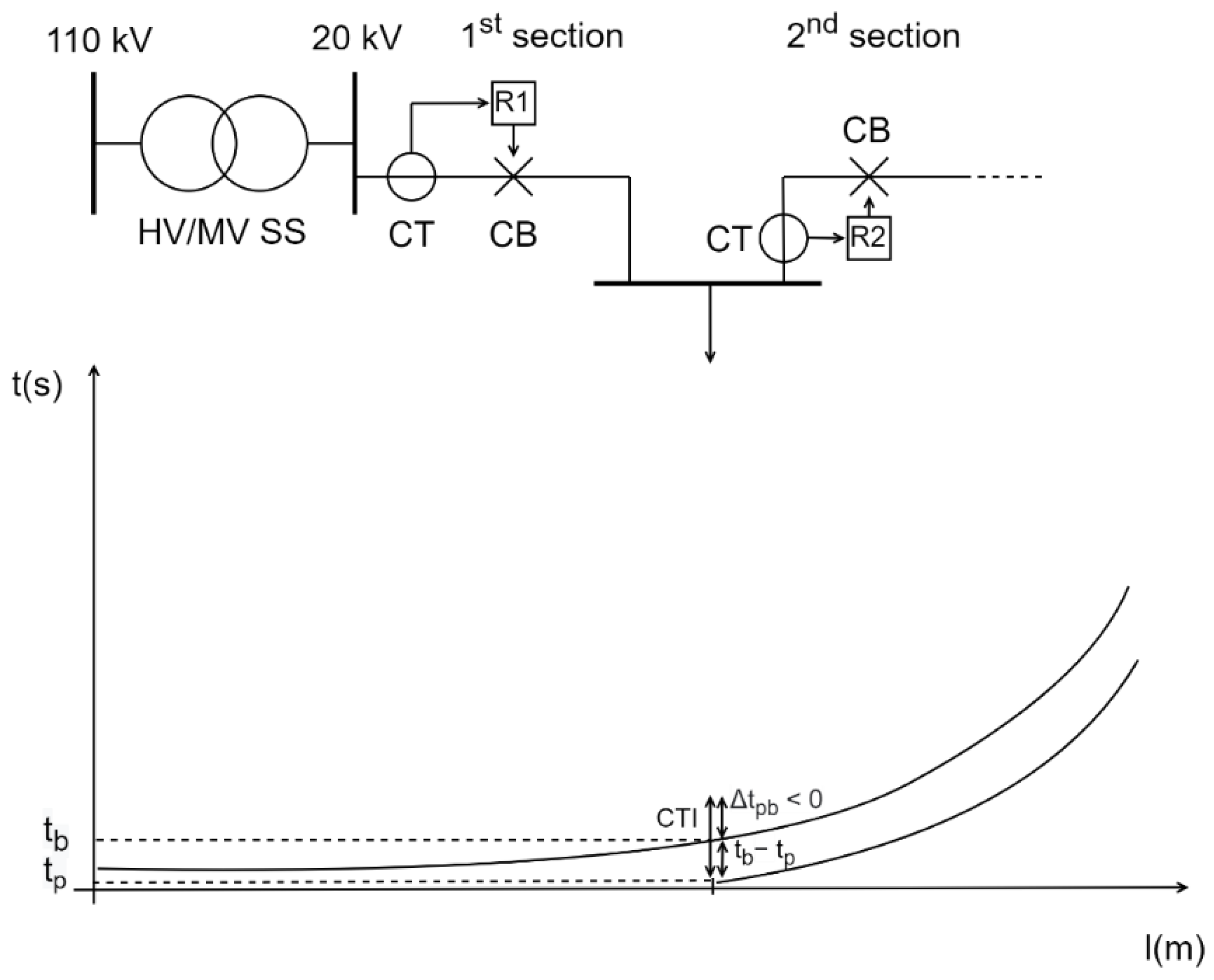
As long as
is a positive value, this is achievable, but the difficulties encountered for the OF2 were those that the algorithm made wrong decisions about in the case of the negative values of
. Thus, miscoordination occurs between a P/B relay pair for negative values of
. This is displayed in
Figure 2. Even though the time–current inverse curves of a P/B relay pair are not mutually intersected, miscoordination will occur if a minimum time period of
did not pass between the operation of primary and a backup relay [
23]. This means both relays had sent a trip signal to their associated CBs. Upon sensing the fault current, the primary relay will send a trip signal to its CB, which must open its contacts in
time. If a minimum time period of
did not pass between the operation of both relays, the backup relay’s internal clock will count the time
, and then will generate a trip signal and send it to its associated CB. This, of course, happens because the primary relay’s CB has not fully opened its contacts (
time has not lapsed), and the fault current is still flowing through both CTs and both relays can detect it. Thus, both CBs will operate and both protected elements (for example, lines) will be de-energized as a result.
In this case, by increasing the negative values of , the final output of OF2 would also increase. Likewise, small values of negative would lead to small final output of OF2, meaning that the optimization algorithm would recognize and possibly accept this as an optimal solution, even if that was the case when miscoordination between a P/B relay pair occurred.
The reason why both parts of OF2 are squared probably originates from squaring the second part of Equation (4), because large positive (and negative) are artificially increasing the value of OF2, thus making it non-optimal. Even the negative , which basically equals miscoordination, is squared and positive, meaning it deteriorates the solution. An even graver mistake would be to remove the square exponent, because then a negative would artificially lower the OF2, enhancing it that way, although this clearly leads to miscoordination between P/B relays. As previously mentioned, the problem can arise for rather small and negative values of time discrimination between P/B relays. For these solutions, a protection engineer must carefully conclude whether to accept them or not, even if the final value of OF2 is minimum compared to all the other cases. This conclusion must be done by observing the whole distribution network, by evaluating and estimating the sensitivity of the load that may be disconnected due to miscoordination, and finally by calculating reliability indices for this case and comparing them to the case where P/B relays operate properly.
The authors’ opinion is that the second part of Equation (4) can be omitted and transferred to a constraint function, mainly because of two reasons. The first is that the instance where a primary relay will fail to operate is rare in practical cases, and when making protection discrimination studies, it is usually advisable to stay on the safe side by completely avoiding miscoordination. By minimizing the primary relays’ operating times, the protection engineer will be sure that the solution is optimal and covers the vast majority of real cases, since numerical relay (and its associated equipment such as CT and CB) failure rate is very low [
24,
25,
26]. The second part can artificially “mask” the results of the objective function OF2, by possibly leading to the situation where all primary relays in the network may not be as optimally set compared to the case where OF2 consisted only of the first part. This is due to the minimization of P/B relays’ discrimination time throughout the whole network. As mentioned, the question of why a protection engineer would even allow a possibility of relay miscoordination for the small number of relay failure practical cases, when even in this case it cannot be guaranteed that the solution is optimal when compared to the situation where the second part of Equation (4) is omitted, remains unclear.
The second reason revolves around the question that, even if the P/B relays’ discrimination time is not removed from Equation (4), for what position along the impedance of the protected element (usually line) should
be calculated? Should it be at the beginning, end or somewhere in the middle? This question cannot be universally answered, since the P/B relays’ discrimination time
is a function that grows with line distance, as was stated in the literature [
1].
Minimizing can be carried out, for example, for the ending node of the protected line, but this still only accounts for a single case, because a short-circuit may occur along any part of the whole line (especially if the example is an overhead line). Although, since should have the highest value at the end of the line, possibly this position can be the worst-case scenario used in Equation (4), and this seemingly makes it justified to use. However, even then, an additional question arises: for what type of multi-phase short-circuit should this condition be checked? Because for an inverse time–current function, a different type of short-circuit will lead to a different P/B relays’ discrimination time . Again, it can be stated in advance that the worst-case scenario will be the occurrence of a two-phase short-circuit at the end of the protected element, and should be checked only for this instance. This is because a two-phase short-circuit current equals 86.6 percent of a three-phase short-circuit current, and this means that, according to the t-I inverse curve, the associated clearing time for both primary and backup relays will be the longest.
However, the above reasons indirectly state that the second part of Equation (4) occurs in rare cases, and including it in the main objective function could lead to a potential situation of relay miscoordination. The authors believe that thorough research of the value of lost load (VoLL) and quantification of negative consequences on network operation and the distribution network operator’s (DNO’s) loss of revenue must be conducted before this part of the objective function can be taken into consideration [
27].
Returning to the existing research in this field, OF2 was rewritten in [
28,
29,
30,
31] in order to resolve some of the aforementioned difficulties. Similar to the case of OF2, OF3 has two terms and is given in the following equation:
The first term represents the operating time of the relay, and the second term represents the modified penalty term. The penalty term is modified in a way that in the case of a positive value of the coordination constraint , the component is equal to zero and the penalty term is equal to . For a negative value of , the component is equal to and the penalty term equals , resulting in a high value when . The weighting factors , and can be adjusted by the trial and error method depending on the optimization application. In each application, these parameters may be changed to achieve the best results and optimize the relay performance. By using this OF, the optimization selection process tends to choose small and positive values of with low values of because the negative values of add a larger term to this objective function. In this way, one of the issues regarding the second part of this type of objective function was solved.
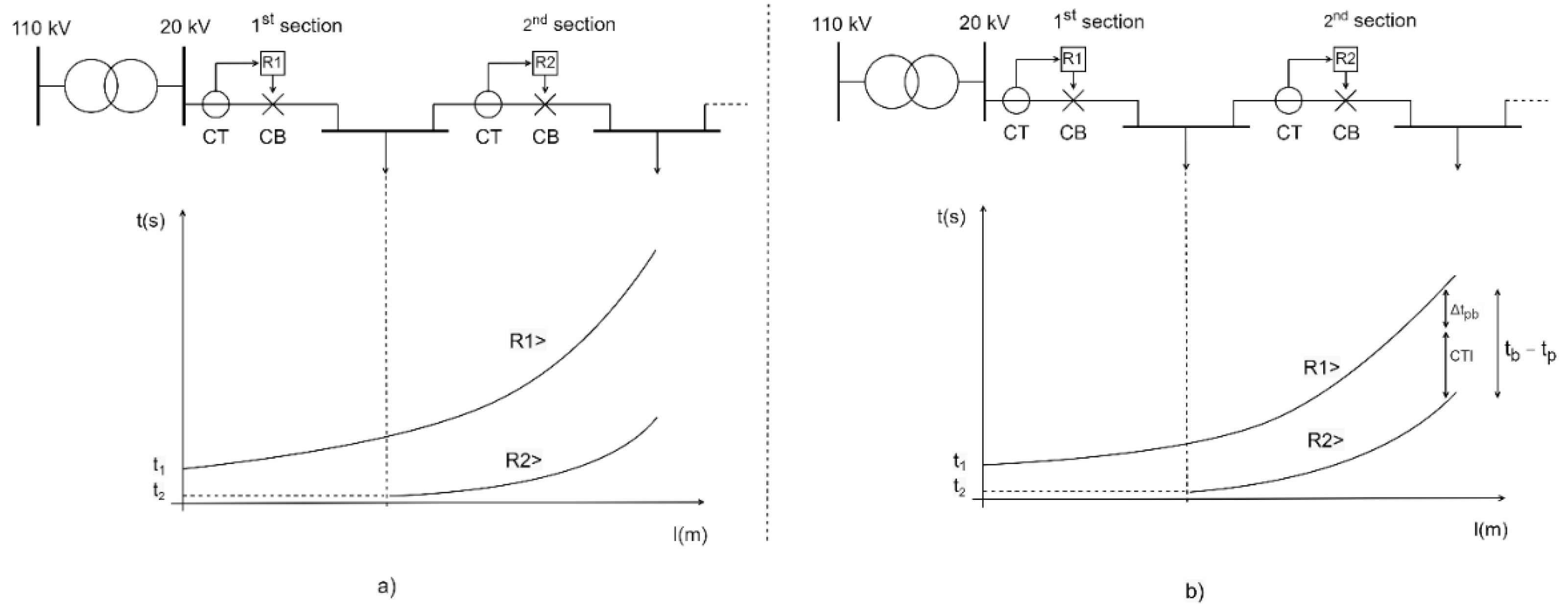
However, other questions still remain open, with the most important being whether OF3 can yield a globally optimum solution by observing and minimizing both the primary relays’ operating time and P/B relay pairs’ discrimination time compared to the case where only primary relays’ operating time is observed. In fact, when only observing the first part of the OF3, the and settings of all primary relays in the network will be adjusted for minimization of their respective operating time. However, when observing both parts of the OF3 simultaneously, the algorithm will tend to flatten time–current inverse curves of all relays; i.e., it will choose and in such a way that P/B relays’ inverse time–current curves become closer.
This difference between an OF where only primary relays’ operating time is minimized and an OF where both primary relays’ operating time and P/B relay pairs’ discrimination time are minimized is displayed in
Figure 3.
The question arises as to which of the solutions is better: to find an optimum by observing only primary relays’ operating time (
and
in
Figure 3a), or by observing both primary relays’ operating time and P/B relay pairs’ discrimination time (
,
and
in
Figure 3b)?
and
settings of all relays in the network for the optimum solution of the former objective function do not have to correspond to the optimum solution of the latter objective function. The weighting factors in Equation (6) can artificially accentuate the part of the equation which is more important to a protection engineer, but there is no universal recommendation as to how much they amount to.
Moreover, it is hard to exactly determine what discrimination time
between P/B relay pairs’ should be chosen along the line, displayed in
Figure 3b. In
Figure 3,
was observed for the end of the relay R2 primary zone (or the end of the R1 backup zone), meaning that its value was the highest along that line. Consequently,
will be easier to optimize (minimize) compared to if it was observed at the beginning of the relay R2 primary zone (not displayed in
Figure 3b). However, there are two downsides if observing any of these parameters; if
is observed on the end of the line (primary zone), then the protection engineer does not know if this parameter is greater than 0 at the beginning of that line. Thus, a miscoordination can occur. This can, however, be mitigated if
at the beginning of the line is separately inspected as a constraint function, and the
at the end of the line is observed as a part of main objective function. The second downside is that if
is observed at the beginning of the line (primary zone), that part of the main objective function will have a much smaller impact on the overall solution, since
has the lowest value at the beginning of the line (this can be observed in
Figure 1). This is not a problem per se, but since the range of this parameter is very low, it may steer the optimization solutions (relays’
and
settings) in such a way that both t-I curves for a P/B pair are dangerously close to
at the beginning of the line. Any deficiency of an associated CB (slower mechanical lever operation due to aging) can easily result in miscoordination.
Finally, in order to steer the answer to the previously raised question of which optimization function is more suitable for usage, one additional important question needs to be answered: can the inclusion of the P/B relay pairs’ discrimination time indirectly cause the deterioration or damage of the protected element? The answer is that using this discrimination time in the main objective function does not guarantee that the aforementioned situation will not occur. Even if is minimised (wherever observed), the primary relay operating time for a certain multi-phase fault, if too slow, may cause deterioration or damage of the protected element. To make matters worse, the same can be stated for the backup relay operating time , but with much greater possibility since , because in the situation if a primary relay fails to operate, the protection goal is to clear the fault in time. However, if that time is too long, the protected element may become damaged before the trip of an upstream relay’s associated CB.
The authors’ opinion is essentially the same as for the previous objective functions, but with an important addition. P/B relay pairs’ discrimination time should be removed from the main objective function and should be included as a constraint function in order to check the possible miscoordination by the breach of
. However, an additional internal check should be added to the optimization algorithm, which will have the ability to test the possible exceeding of the thermal equivalent short-circuit current
for both the primary and backup relay [
1]. For this to be realised, relay operating time
should be separately inspected for different cases of fault currents, as will be briefly explained below. By using the following equation, relay operating time
will be calculated by inspecting three-phase and two-phase short-circuit current at the beginning and at the end of the protected element:
where
is the actual short-circuit current flowing through the element,
is the relay operating time, and
is called the thermal equivalent short-circuit current and it can be found in the electrical design documentation of cables and overhead lines (OHLs).
This subroutine check of an optimization algorithm will ensure that the fault current flowing through the protected element (for example, line) for a time period until the relay operates will not over-exceed design documentation specification data. The reason why the authors propose the inspection of for different faults at the beginning and the end of the protected elements is that even a low can be a cause for damaging an element, if the short-circuit current flowing through the element is high enough, and vice versa.
Finally, when all these cases are calculated for an element, and if there is even one case in which Equation (7) is breached, the optimization solution should be deemed infeasible and must be completely removed from the optimization process, since it can result in a serious damage to the protected element. As previously mentioned, this constraint needs to be checked for both the primary and backup relay, since a situation where the primary relay fails to operate must not lead to deterioration and/or damage of the protected element before the trip completion of backup protection. In other words, both primary and backup protection clearing times should be lower than calculated on the basis of Equation (7) for a protected element.
If this criteria is not met, and if the actual short-circuit current flowing through the element is greater than in its respective time, the generated heat will start to melt the copper or aluminium wires, thereby deteriorating its mechanical and electrical parameters (in case of cable lines, the insulation will start to deteriorate first).
Continuing the existing research in this field, another modified OF was given in [
32], where the authors were looking for an easier-to-work-with function that could serve the same purpose as the OF given in [
28].
Authors in [
32] stated that OF2 and OF3 presented in previous research could not guarantee that the best coordination was obtained, or that the smallest operating time of the relays was achieved, due to the existence of the weighting coefficients. They came out with the solution in which OF4 did not need weighting coefficients, meaning that the ambiguity of the weights (trial and error manipulation) in the OF4 was eliminated and was replaced with a definite value. Authors in [
32] compared their optimization results with results of the previous methods and concluded that the optimization results accomplished with OF4 were very similar to the results of the OF3.
Although the OFs presented in [
28,
32] mainly solved the coordination problem, the difficulties of the larger operation time of the backup relays still existed. As previously mentioned, the fact that the operating time of the backup relays was higher than desired could lead to a possible harmful effect on the electrical equipment, since it has to tolerate the fault for a longer period of time. In order to eliminate the negative aspects of the aforementioned OFs, a new objective function for protection coordination was proposed in [
33,
34], where the authors added a new expression to the OF given in [
28] and demonstrated that the operating time of the primary and especially the backup relay decreased significantly.
In the case of a negative value of , the component is equal to . Similarly, for a positive value of , the component is equal to . From Equation (9), it can be stated that higher positive value of suggests a larger value of operating time of backup relays, and in that case, OF5 minimizes the operating time of backup relay according to Equation (5). Likewise, a higher negative value of suggests a larger value of operating time of primary relays, and OF5 minimizes the operating time of the primary relay , also according to Equation (5). For negative and positive values of , OF5 minimizes the operating times of primary and backup relays, respectively.
This improvement over the previous objective functions definitely paved the way to a situation where the occurrence of potentially dangerous optimization solutions (too long P/B relay operating times for a particular protected element) was drastically decreased, but again there is no guarantee that it will be 100% avoided. Due to the nature of the OF in Equation (9), where a sum of primary relays’ operating times and P/B relay pairs’ discrimination time is observed for the entire network, a situation can occur where a particular part of this sum can overshoot the thermal equivalent short-circuit current of a protected element. In simpler terms, there can be at least one relay or a P/B relay pair in the network, which will, due to its slow reaction, cause damage to the protected element, although the total sum of the primary relays’ operating times and P/B relay pairs’ discrimination times for the entire network is minimal. It is the authors’ opinion that the only way to completely avoid this possibility is to remove P/B relay pairs’ discrimination time as a part of the main objective function and transfer it to a constraint function. Additionally, for each protected element, the relay operating time for both the primary and backup relay should be separately inspected for different cases of fault currents, in order to avoid possible exceeding of the thermal equivalent short-circuit current .
Returning to the continuation of research on this subject, OF5 managed to solve the problem with a larger operating time of backup relays and a larger discrimination time, but on the other hand, there was still that occurring problem where the algorithm provided the best optimization solution in some cases where had negative values (miscoordination).
Due to the reason that each of the previously mentioned OFs suffered either from miscoordination or larger operating time of relays, authors in [
35] proposed a new OF.
For the positive value of , OF6 works in the same way as OF5, meaning that for larger positive values of , OF6 minimises the operating time of backup relays. In the case of a negative value of , the component + is equal to ). When miscoordination occurs (negative ), OF6 minimises the operating time of primary relays and maximizes the operating time of backup relays.
Therefore, authors in [
35] stated that OF6 completely resolved the problem of miscoordination between the P/B relays pairs. In the comparative analysis with existing OFs, the authors showed that the proposed OF significantly minimized the operating time of P/B relay pairs, and also kept the discrimination time between P/B relay pairs at the prescribed level. Albeit significantly upgraded compared to other objective functions described before, even this one cannot guarantee the avoidance of possible exceeding of the thermal equivalent short-circuit current. Additionally, it cannot guarantee that an optimum solution is actually better than the solution of the objective function where discrimination time between P/B relay pairs is completely omitted. As previously stated, transferring this constraint to an objective function and penalizing it still remains a concept to be further debated, due to the reason that relay malfunction is rare in practical cases.
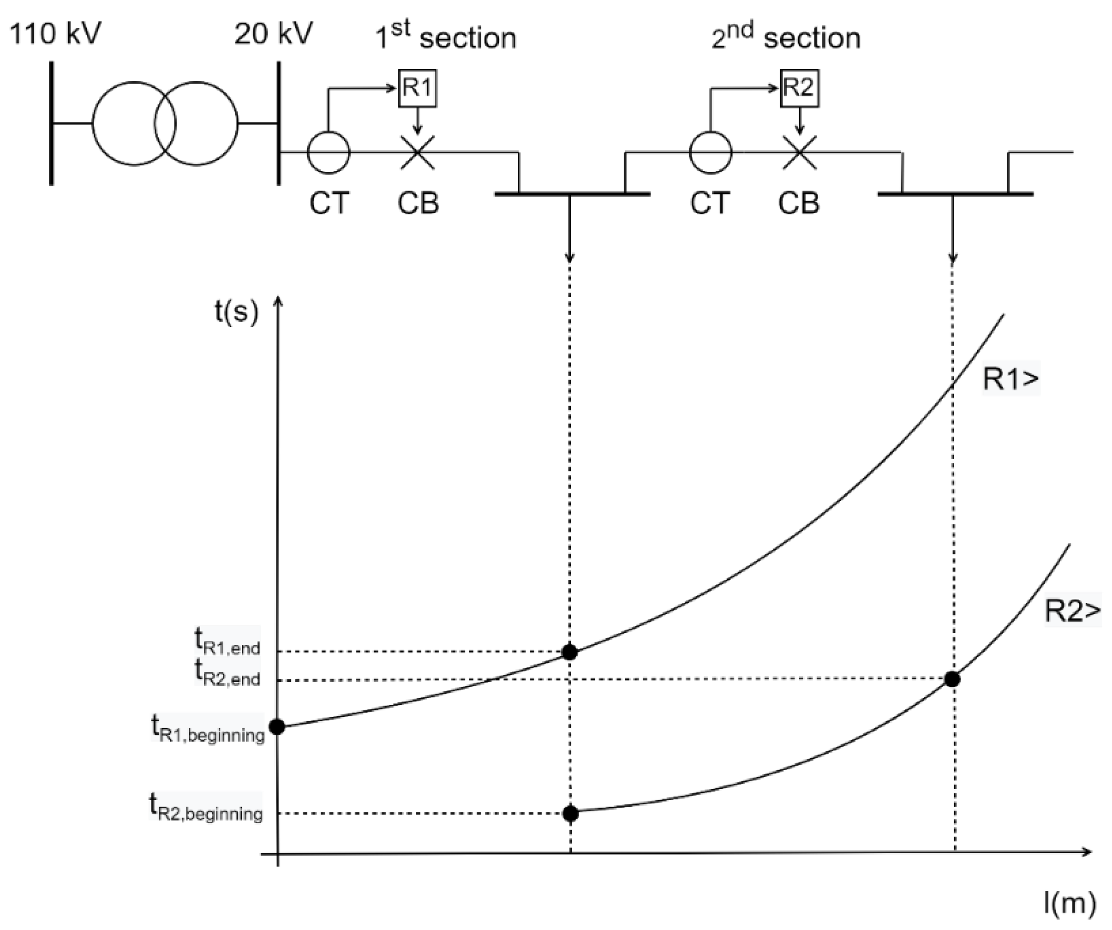
Finally, it can be stated that the existing research on the topic of relay operation optimization has definitely experienced significant progress from its inception, and all the mentioned OFs had excellent theoretical background and ideas to solve the OCR optimization problem. On the basis of this review article, authors plan to modify the traditional OF function for the purpose of their future research in order to address the aforementioned challenges. The idea will be to optimize relays’ operating time only for the primary protection zone, but unlike in previous articles,
would be calculated both for the beginning of the line and the end of the line (
and
). In this way, the main OF would revolve only around cases which frequently occur in practice, whereas relay malfunction and backup relay operation would be transferred to a constraint function. By minimizing both
and
, the algorithm would tend to choose t-I functions which would be more “flattened” for the relay primary protection zone; consequently, even P/B relay pairs’ discrimination time
would be smaller, due to the relative vicinity of both curves. This is displayed in
Figure 4 for relays R1 and R2.
However, it must be noted that the goal of this OF would not be minimizing , so it cannot be expected that the discrimination time between a P/B pair will be minimal. The aforementioned parameter will be transferred in a constraint function, described by Equation (5). The purpose of the constraint function will be to completely avoid miscoordination between any P/B relay pair. Thus, will not be breached throughout the observed network. Moreover, an additional constraint will be added for the OF, and each protected element (line) will be checked for possible exceeding of the thermal equivalent short-circuit current for both the primary and backup relay. The aforementioned constraint will be inspected for the two-phase and three-phase short-circuit at the beginning and the end of the protected element. Thus, a protection engineer will be sure that the results of the optimization algorithm, although nominally satisfying the OF and its first constraint, will not cause damage and/or degradation of all protected elements in the network. The authors, of course, plan to compare their results with the results of the previously mentioned OFs in order to test and validate their hypothesis.
In order to carry out further research on this topic, there are some open challenges that will be addressed in the subsequent chapters. These challenges do not only revolve around the optimization function per se, but rather on the introduction of distributed generation and its associated bidirectional power and short-circuit flows, and on the way a distribution network is operated.
3. The Impact of Distributed Generation Units on Distribution Networks’ Operation and Protection Philosophy
Although distributed generation (DG) units were defined, known and used in traditionally passive distribution networks from their beginnings (for example, small hydro-electric power plants), they became widely and massively introduced from the onset of the 21st century. Stringent environmental laws, rapid advancement in DG technology and various new types of generation units (photovoltaic power stations, wind farms, biogas/biomass power plants, geothermal power plants, etc.) led to a situation where DNOs faced a great number of connection requests that were not standardized at the time [
36,
37,
38]. Of course, financial stimulation of independent power producers (IPPs) via governmentally guaranteed feed-in tariffs greatly contributed to the exponential rise of those requests, and the passive distribution network had to change its role to an active one in a very short time span [
39,
40].
Due to the fast advancement and consequently lower capital costs of DG technologies, feed-in tariffs were gradually replaced with premium tariffs, and eventually DG units began to join market clusters [
41,
42,
43]. These clusters are termed virtual power plants, which basically denote a joint combination of different IPPs and their respective DG units, forming a separate entity in the electricity market. In this way, governments can relieve electricity end users and industries of their increased electrical monthly bills for financing DG producers; however, in a way to compensate this shortcoming for DG owners, their facilities still retain priority grid access to produce electricity over conventional fossil fueled power plants.
From a distribution network point of view, DG units are classified as production facilities connected on a low voltage (<1 kV) or a medium voltage network (≤35 kV). Their output power can range from a few kilowatts up to approx. 10 MW. Although there was a debate over the definition of the DG upper boundary, nowadays, it is almost universally accepted as 10 MW [
44]. DG units, if located and sized properly, can have a beneficial role for the distribution network operation [
45,
46,
47]. This is mainly because of lowering network line and transformer losses. However, there may also be some challenges associated with their connection to the distribution network which must be addressed and resolved. DGs can cause overloading of adjacent lines, especially if they are of lower cross-section due to the still present (albeit decaying) passive topology of distribution networks, and they can also cause overvoltage problems due to bidirectional power flows. In extreme cases, HV/MV substations, which were up until recently considered as feeding stations for the distribution networks, may actually inject power to the upstream transmission network. This, however, occurs only for HV/MV substations which supply power to their respective distribution networks with a significant amount of DG units, and only in the periods of light load (usually during the night) when DG units produce maximal output power (for example, wind farms).
Regarding the protection philosophy with DG units included, there are basically a few situations where DGs can significantly influence protection settings and CB ratings. First, in
Figure 5, a typical connection of a DG on a medium voltage (MV) distribution network feeder is displayed. It must be noted that this is only one (albeit very often used) type of DG connection, and others may be used depending on DG output power, carrying capacity of distribution network lines and/or hosting capacity of a feeding HV/MV substation.
In this particular case, DG is connected on a MV switchboard called the point of common coupling (PCC). A circuit breaker, numerical relay device, current transformer and a voltage transformer (VT) are directly placed on the busbars of a PCC station (the latter not being displayed in
Figure 5) and are owned by a DNO. On the secondary side of a CT and VT, a metering device is connected, which measures and stores the data on electrical energy and power being transferred from the DG unit towards the network (and vice versa, during the maintenance period of a DG unit). The meter is also owned by a DNO, but its data have to be available to the IPP for transparency reasons. In the not so distant past, this usually only meant that the meter had to be physically available for the IPP, meaning that the DG facility’s maintenance engineer could have visually observed this data. However, today, this usually means that the data is being remotely transferred towards the IPP’s station computer via communication lines (although physical availability of the meter is still mandatory). DNO has the sole control of a busbar CB and can operate it remotely. IPP’s ownership consists of a cable leaving the switchboard, transformer and, of course, the generator along with its prime mover and adjoining equipment. In the case of a photovoltaic system, instead of a generator and prime mover, there is an inverter and a PV array.
The numerical relay operating the busbar CB usually consists of under/over voltage protection (U<, U>), overcurrent protection (I>), under/over frequency protection (f<, f>) and islanding protection. The last three are actually only used for preventing the formations of energy islands if the main network experiences a blackout [
48]. The forming of an energy island, while beneficial in certain cases (improving reliability indices such as SAIFI, SAIDI, ENS, etc.), can often present a peril for distribution network elements and especially the generator, which will be discussed soon. In the case of a fault on the 1st section in
Figure 5, relay R1 will send a trip signal to its associated CB, which will open its contacts. If the feeder load is greater than the available power of a DG, under frequency protection at PCC will open the busbar CB and disconnect the DG from the network, thereby preventing island operation. The same occurs in the opposite situation, i.e., if the feeder load is lower than the available power of a DG, over frequency protection at PCC will open the busbar CB and disconnect the DG from the network. It is important to mention that in this latter case, DG’s governor can easily regulate its output power to match the now-reduced load (before the R1 and CB operation, DG was actually covering the whole feeder and exporting excess power towards the other feeders of the HV/MV substation); however, this must not occur, since then an energy island would be formed.
Why is this so dangerous for equipment and network elements? For example, if the feeder consists of overhead lines, then most certainly an automatic circuit recloser (ACR) system is used to automatically switch on the CB after a specified time (usually 0.4 s and another one after 40 s), in order to re-energize the feeder. This is done in order to clear temporary or non-permanent network faults and/or disturbances, and to maintain favorable reliability indices for the DNO. However, if an ACR system recloses a CB of relay R1 while an energy island was formed by a DG, then it is almost certain that the island will experience asynchronous reclosing or wrong synchronization. This means that the frequencies of the island and the main network may not be matched, nor may their respective voltage magnitudes; however, in practical cases, the most dangerous parameter is the phase angle between the network and DG (island) voltage. Frequency and voltage magnitude of a generator are pre-set and regulated by the governor and automatic voltage regulator (AVR) system, and it can be stated without much opposition that these parameters will correspond to the frequency and voltage of the main grid [
49,
50,
51]. However, this cannot be stated for the phase angle between the network and generator voltage. The worst-case scenario is that they are in opposition, because then a high equalizing current will flow between the grid and DG, potentially damaging or downright destroying network elements in its path.
Even worse is the situation where, when a breaker opens its contacts after a trip signal from its associated relay R1, the feeder load exactly in this moment completely matches the DG output power. Albeit not highly probable, this situation would mean that the DG seamlessly goes into island operation without its governor or AVR system even detecting the island formation. Thus, a relay R5 in
Figure 5 will also not detect island formation, and as a direct consequence, a busbar CB will not react and open its contacts. After ACR sequence completion, this will, of course, cause an asynchronous reclosing and possible grave damage to the network elements. For that reason, new and advanced methods are being developed to detect this specific island formation based on local or remote parameters (for example, signaling the trip state of upstream CBs via communication network, etc.).
In addition to overvoltage problems, which can be solved either by modifying overvoltage protection in existing numerical relays or by setting the generator’s AVR regulator in voltage control mode (with a goal to maintain the PCC voltage magnitude), the most important parameter for a fault state such as a short-circuit is the under voltage protection [
52,
53]. Its main goal is to disconnect the generator from the grid in case of a rapid and substantial voltage drop (usually 50–60%
), which without a doubt standardly accompanies multi-phase short-circuit faults. For earth faults, on the other hand, the voltage profile of the network will be different, however in this paper the authors will only focus on multi-phase faults. By using under-voltage protection, DNO basically ensures that the DG will be disconnected in the case of any multi-phase fault on the feeder, and since forming of energy islands is not allowed (for now, at least), using directional protection on the end side of lines is simply not used. However, since DNO is transitioning towards the distribution system operator (DSO), which practically follows the transitioning of a once passive network to a smart grid, island operation will surely become a desired option in the near future. This will partially be addressed in the next chapter of this paper and in the authors’ subsequent research articles.
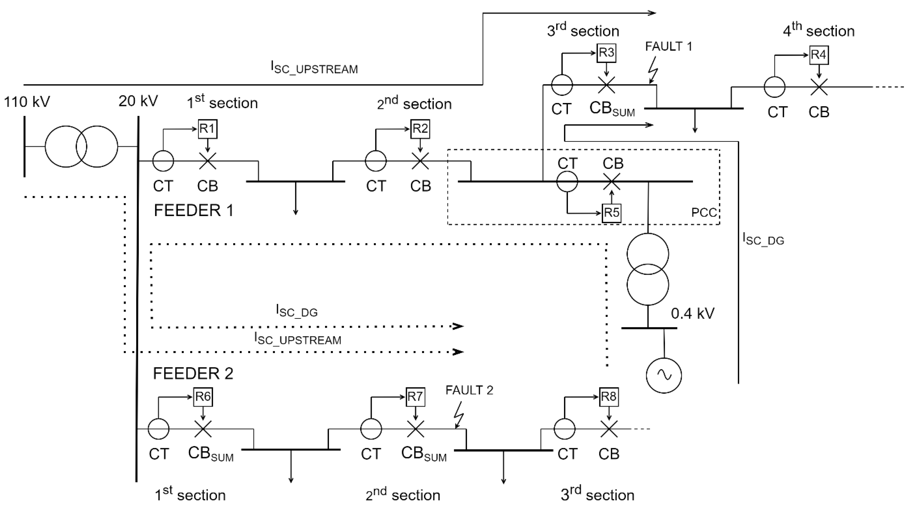
There are finally two distinctive situations regarding the usage of overcurrent protection in networks with DGs. One is concerned with the possible increase of the breaking capacity of the CB and the making capacity of the CB and busbars [
54,
55]. This occurs on a feeder where a fault is located downstream of a DG and the complex sum of DG fault current and upstream network fault current flows through the same CB, as is displayed in
Figure 6. Here, Fault 1 is observed on the 3rd section of Feeder 1, and a CB through which both contributing fault currents flow is denoted as CB
sum. Almost the same case occurs on Feeder 2 of the same figure, where a DG located on Feeder 1 feeds the short-circuit (Fault 2) located on its 2nd section. All the CBs through which both contributing fault currents flow are denoted as CBs
um. Both the upstream network fault and the DG fault current are displayed, with a dotted line for Fault 2, in order to differentiate it from the case of Fault 1 on Feeder 1.
The grave problem with these two cases, describing the same situation occurring after the inclusion of DG unit(s), is the following: if the breaking capacities of the CBs through which the increased fault current flows have been exceeded, they will simply fail to open their contacts. This is due to them probably being partially or completely melted. Moreover, in the case of exceeding the making capacity, busbars may be ripped out of the supporting insulators due to large electrodynamic forces [
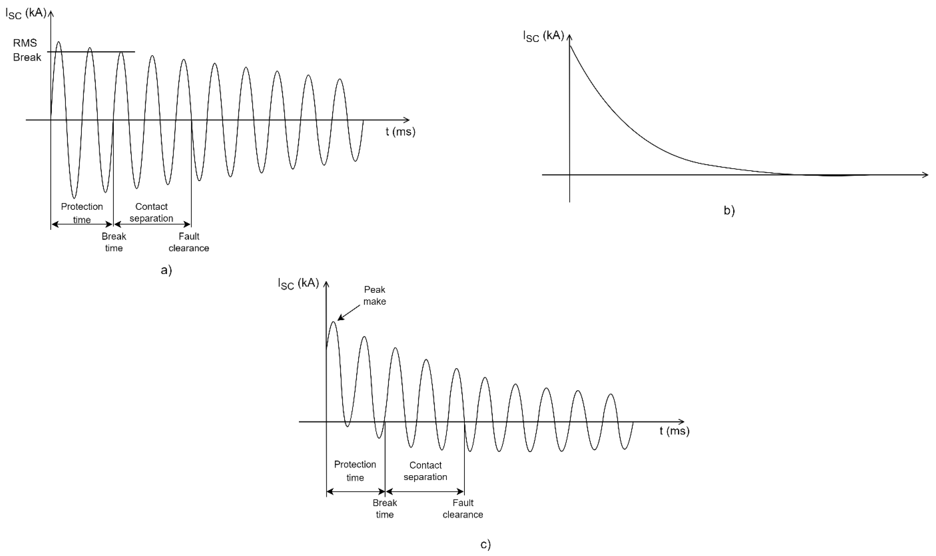
56]. The breaking capacity of the circuit breaker refers to the maximum current in the root means square (RMS) value that the circuit breaker can interrupt [
57]. More precisely, it is the RMS value of the AC component of the fault current at the time the CB contacts separate, and it does not include the effect of the DC component of the short-circuit current. This is displayed on an oscillogram denoting a general waveform of a short-circuit current in
Figure 7 (part a).
The making capacity of the circuit breaker is greater than the breaking capacity, and it is the maximum (first cycle) peak value of the current that the breaker can interrupt without any damage if the breaker is closed at fault (for example, this occurs after the completion of an ACR sequence in a OHL feeder with a permanent fault). It includes both the AC and DC offset components, of which the latter is linked to the timing of the short-current occurrence in regards to the sine network voltage. If the short-circuit occurred in an instance when the network sine voltage was equal to 0, then a maximum DC component would be induced.
In other words, the making capacity of a circuit breaker is the maximum current which the breaker can conduct at the instant of closing. The making capacity, unlike the breaking capacity, is not defined only for CBs, but for all switchgear equipment through which a short-circuit may flow because the peak value of the first cycle is the most severe from an electrodynamic perspective. This includes busbars, supporting structures, flexible connections, conductors, current transformers, wall bushings and disconnectors, which must also be capable of withstanding the short-circuit current making capacity. The making capacity is expressed as a peak value as the DC offset during fault conditions is taken into account (all parts in
Figure 7).
It is precisely for this reason that all existing switchgear and equipment must be thoroughly analyzed and examined before DG connection, in order to upgrade them, in case the DG(s) contributing current results in the exceedance of their breaking and making capacities. Thus, only maximum multi-phase fault currents are observed (usually three-phase short-circuit current), and the previously described calculation is only relevant for CB (and other equipment) dimensioning. This observation, however, at first seems not to be directly linked with protection coordination, because for the OCR optimization, only minimum short-circuit currents must be observed (the only exception being the calculation of I >> protection for definite-time OCRs). For example, plug setting or pick-up current from Equation (2) is defined only for minimum short-circuit currents. In addition, definite-time relays react with the same time delay, irrespective of the amount of fault current, provided that it is higher than the pre-set pick-up value [
58,
59,
60]. However, when used in networks with inverse relays, as is the case for OCR optimization problems, those relays through which both the upstream and DG contributing currents flow will actually trip faster according to the inverse t-I characteristic. In summary, it can be stated that the DG contributing current has an impact not just on equipment dimensioning, but also on relay setting, albeit the latter being valid only for inverse-type relays.
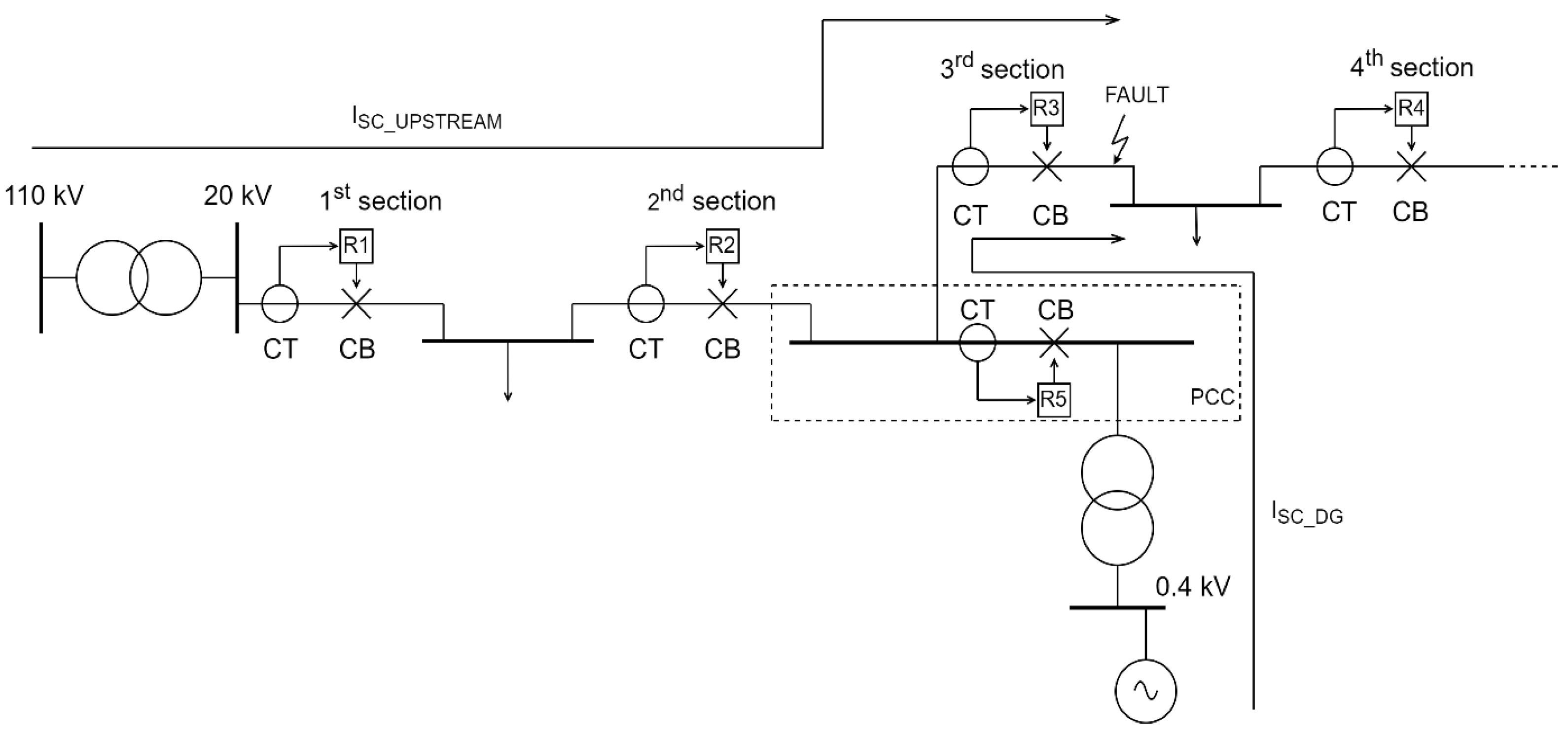
Finally, a distinctive situation regarding the usage of overcurrent protection in networks with DGs will now be described, and it revolves around minimum OCR settings and optimization. If a fault in
Figure 8 occurred after a DG unit, as previously discussed, all the CBs and associated relays located downstream of a DG will have an additional DG contributing current flowing through them (along with standard upstream network fault current). However, the CBs and relays (R1 and R2) between the HV/MV transformer and a DG will now experience a reduced current compared to the case where DG was not connected to that feeder. This is because the contributing current from the main grid (substation) is a function of DG, line and upstream network impedance [
61].
For example, for
Figure 8, an equivalent circuit would have to be made, as is displayed in
Figure 9.
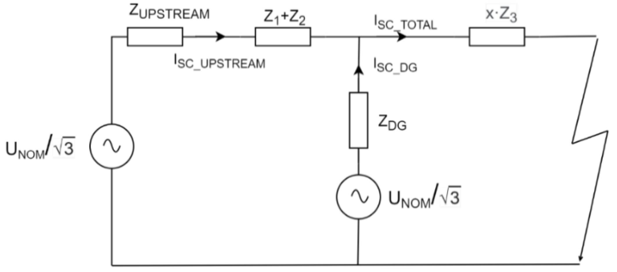
On the basis of that figure, the equation for upstream (main grid) contributing current would be written as:
where
is the sum of synchronous reactance of the generator and reactance of its associated transformer (including their resistances),
is the equivalent impedance of the upstream network (including generating units, transmission grid and the impedance of the HV/MV transformer), while
,
and
represent the line impedance of 1st, 2nd and 3rd section, respectively. Next,
denotes the distance between the PCC and the place on the 3rd line section where the fault occurred, and that is why
is actually a part of the 3rd line section. Finally,
denotes the total short-circuit current at the place of short-circuit, which consists of both the DG and upstream network contributing current and, in the case of a three-phase fault, is equal to:
is the line voltage of the faulted network, and
is the equivalent impedance of the circuit displayed in
Figure 9, which is equal to:
It is worth emphasizing that all mentioned electrical parameters are referred to as complex numbers, needed to solve standard AC circuits. Summarily, in cases when the DG unit and the substation are feeding the fault in parallel, relays between them will under-reach their respective protective zones. In other words, they may become “blind” to some types of short-circuit currents occurring on that feeder downstream of a DG unit. Thus, if the settings of those relays are not changed (lowered), then a realistic possibility is that they may not sense those short-circuit currents. Of course, one important thing must be accentuated, and it regards the fact that those mentioned relays are actually backup relays, which means they should operate only in the case the relay(s) closest to the fault malfunction. Nonetheless, their reserve role is significant and cannot be omitted, and for that reason, all the relays of a network where a DG plans to be connected must be inspected for possible cases of protection “blinding”.
As an introduction to the next chapter, a few questions and considerations will be presented regarding distribution network’s operation in the presence of DG unit(s). When connected onto a radial feeder, a DG unit will create a partially meshed network. The word “partially” used here means that, although the upstream network and DG are working in parallel (they can be considered as two separate power sources), a DG unit in most circumstances cannot be considered as a stable source, at least not by a transmission network operator’s (TSO’s) standard. First of all, this is because a large portion of DGs are intermittent sources (photovoltaics depend on the sun availability, wind farms depend on the occurrence of wind, etc.), meaning they cannot be included in a contingency (“n − 1”) and reliability analysis. Although intermittent power sources are used in transmission networks, TSO’s contingency analysis does not rely on them, but instead on stable sources which can reroute the supplemental power via parallel lines and/or upstream networks, due to its mesh operation. Having a HV/MV transformer and a DG as the only sources in a previously radially operated feeder means that, by losing the upstream network, the feeder will remain fed only by an intermittent DG. This will usually result in its fast disconnection due to under/over frequency trip.
Secondly, which is more important, and it regards the “stable” DGs like biomass and biogas power stations, is the fact that island operation is not allowed in most countries. Unfortunately, this is standard European practice, despite the fact that those DG sources can theoretically provide stable backup supply [
62]. Thus, an instantaneous backup supply of the load is not possible in case the upstream network is unavailable (due to fault or maintenance). For that reason, the protection philosophy in practical cases is only slightly upgraded compared to the standard radial operation. For example, European MV networks have only one relay device (I>) at the beginning of the feeder, and, if a DG is connected, a relay will be installed in the PCC which will have under/over voltage and frequency protection. The latter is, as already said, used for preventing island operation. All the other lines of the feeder will not have their own relays, and will rely solely on one relay device at the beginning of the feeder.
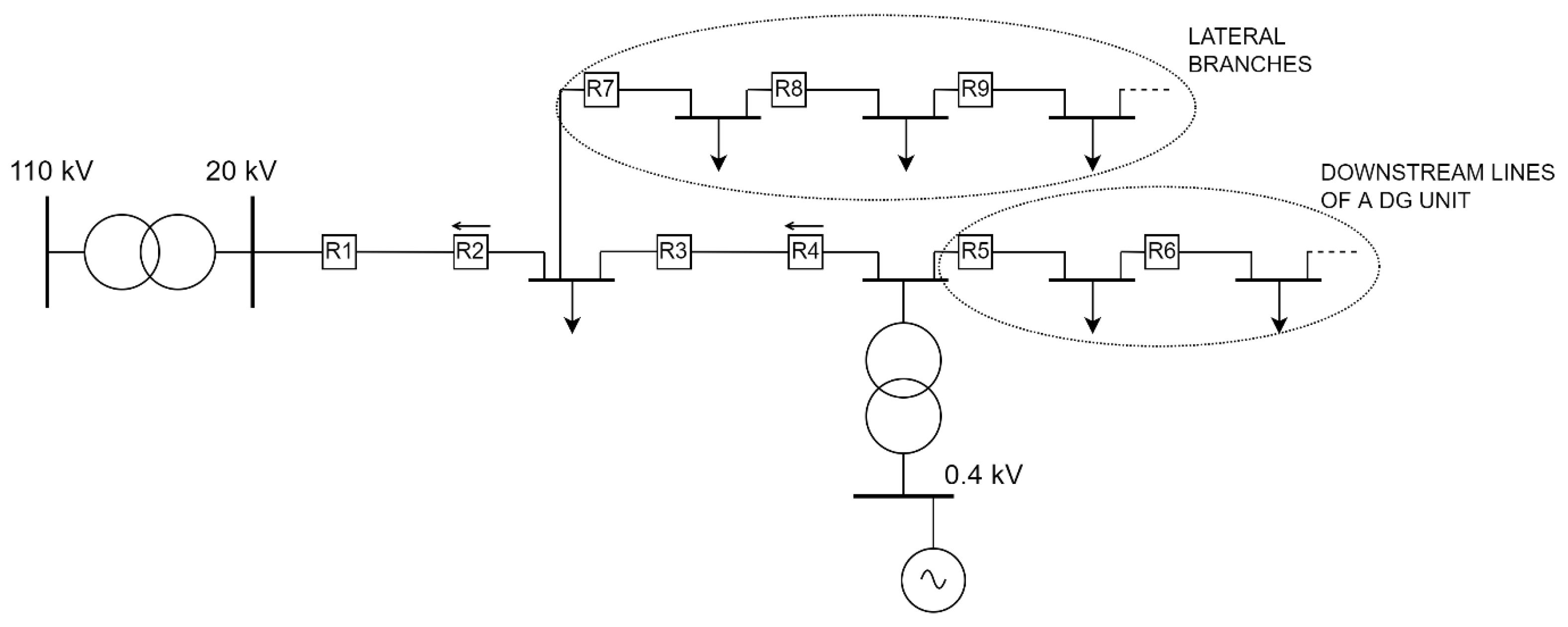
In order to mirror TSO’s standards for network reliability, parallel lines would have to be added in the network and, most importantly, the existing lines between the feeding HV/MV substation and a DG would have to be protected on both sides. The authors will focus on this next step in active distribution network planning and operation in their future research. The aforementioned statements mean that new relays would be installed throughout the network, with an important distinction that directional relays would be inserted at the end of each of those lines. This would be done in order to ensure the shortest possible tripping time of both relays protecting a faulted element, thereby isolating it effectively. Only in this case would the DNO accomplish a similar level of TSO’s reliability standard, where load supply is continuous and not affected by faults in its network. It is important to add that lines which are downstream of a DG unit and lines that form lateral branches will be protected only from one side, since they have no possibility of backup power supply. Moreover, a fault occurring on those particular lines cannot be fed from two sides, as no bidirectional short-circuit flows are expected. All the aforementioned considerations are displayed on an example of a partially meshed distribution network in
Figure 10, which has an updated protection philosophy.
Figure contains only relays, while CBs and CTs are omitted for simplicity reasons. In addition, the protection of the distributed generator and its associated transformer is not displayed, because it is usually not covered by OCR optimization. It is important to note that by using this upgraded protection philosophy, also termed as protection “in depth” of the distribution network, there is no more need for having a protection device in PCC. The reason for this lies in the fact that PCC protection had a single goal to disconnect a DG unit from the network in order to prevent an island operation, but it is the authors’ opinion that island operation will be encouraged in the near future, albeit only for stable DGs [
63]. This is because only those types of units can guarantee their continuous operation when signing a bilateral agreement with a DNO for the provision of ancillary services. In summary, when transitioning from a DNO towards a DSO, TSO’s standards for network reliability and security of supply will be more and more implemented.
When observing
Figure 10, it is also important to note that only DGs with synchronous generators directly connected to the network will be used for OCR optimization. This is because DGs which connect to the network via converter interface have a small contributing short-circuit current and, in that case, directional overcurrent relays cannot be used as they would simply not detect it.
The aforementioned observations were made for a topologically and operationally radial distribution network where a DG unit was connected, thereby changing it to a partially meshed network. However, what happens when a DG unit is connected to a closed loop (or ring), or even an interconnected network? An even more interesting question is, can a distribution network without DG units safely work in a closed loop or interconnected form, but with meshed operation (all the previously opened disconnector switches are closed)? These questions will be answered in the following chapter, firstly for a distribution network without DGs, and then finally, the inclusion of DGs will be taken into consideration.
4. Meshed Distribution Network Operation
In almost every example of a distribution network with objective function similar to those mentioned in
Section 2, meshed network topology and operation is taken as a main presumption [
6,
7,
8,
9,
14,
18,
19,
20,
21,
22,
28,
29,
30,
31,
32,
33,
34,
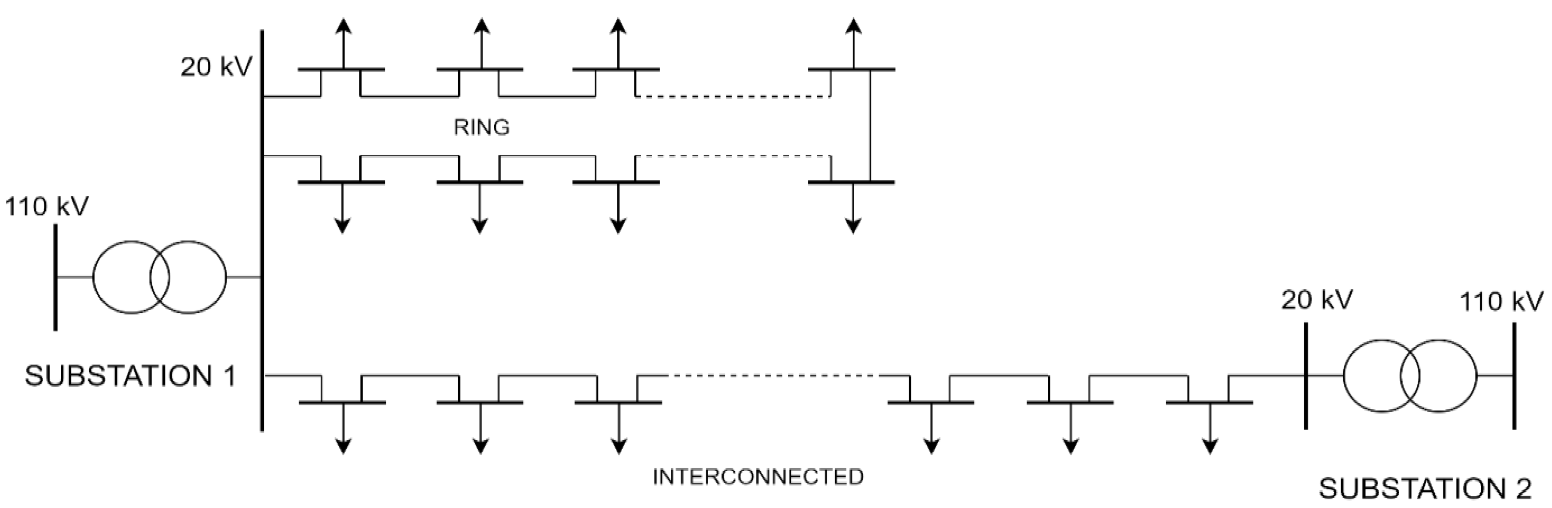
35]. This type of operation is displayed in
Figure 11, for a ring network topology and an interconnected network topology. Every MV/LV transformer, its LV busbars and LV consumers are aggregated and depicted as arrows connecting directly to MV busbars for simplicity reasons.
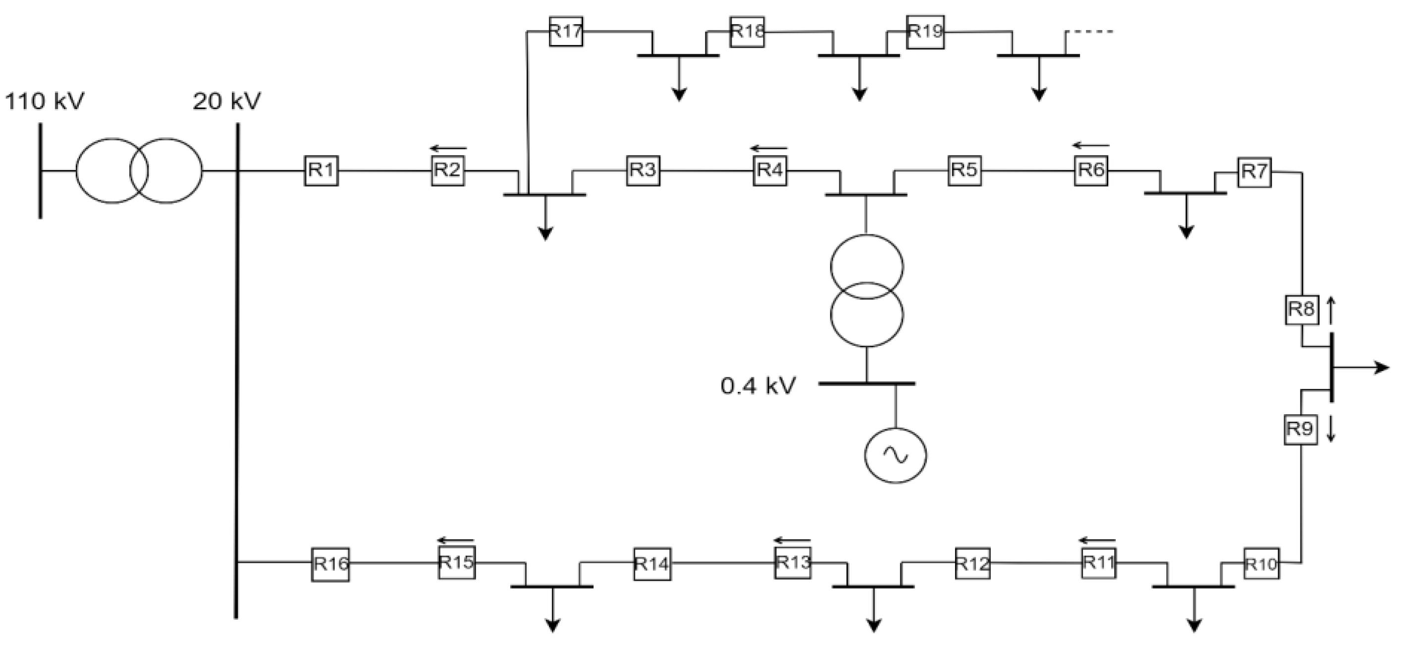
The main feature of both topologies is that, in the case of a fault on one line, the electrical supply can be ensured from other feeders, either from the same feeding point (Substation 1), which is characteristic for ring topology, or from an adjacent one (Substation 2), which is characteristic for interconnected topology. If operated as a mesh network, this will be done almost instantaneously, after the CBs have isolated the faulted line from both sides. Protection from both ends of a single line is almost a universal feature of meshed operation, which is displayed in
Figure 12 for an even number of lines between two feeding substations. Relays must be time graded for each feeding point separately. For example, relays R7, R5, R3 and R1 are related to Substation 1 and must be time graded beginning from R7. The same applies for relays related to Substation 2. More importantly, R2, R4, R5 and R7 must be directional relays. This is because if the fault, for example, occurs on the 2nd line section, R3 and R4 must react the fastest. If there were no directional relays in the network, and depending on the setting current, R2 and R7 would react first, thereby shutting down the whole network in
Figure 12.
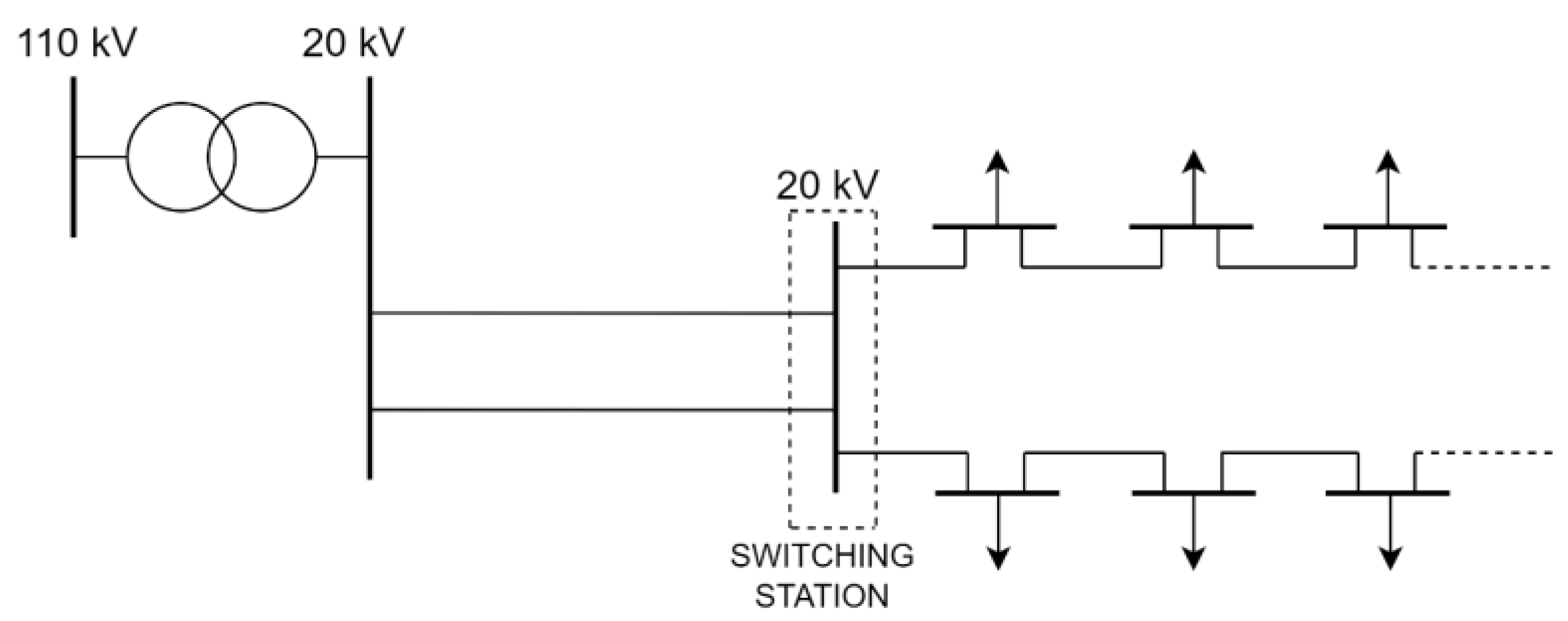
However, as was thoroughly explained in ref. [
1], this protection philosophy is not used in European distribution networks, at least not for now. Distribution networks in European DNOs’ practice are radial in operation, although they may be topologically radial (rural areas) or have a ring (towns and edge urban city areas) or interconnected form (usually city centers). Thus, feeders are protected usually by one relay at the beginning, and mostly no directional relays are used. Albeit, there are exceptions, for example, when using a network with a switching station as a support point, fed by parallel lines. This configuration is used for situations where an existing substation is abandoned (MV/MV substation is replaced by a relatively adjacent new HV/MV substation with increased capacity), but instead of it being decommissioned, its busbars and switchgear are retrofitted and used as a switching station. This is done in order to connect the geographically distant load with the new HV/MV substation. Of course, the substation and switching station will be connected with two or more clean parallel lines (“clean” meaning that no load is directly connected on those lines), as is displayed in
Figure 13. In this situation, due to using parallel lines, directional overcurrent protection must be used at the ending of each of those lines.
Continuing with the previous discussion, when operating ring or interconnected distribution networks in a radial manner, a tie line will be formed by opening a switch disconnector in a MV switchboard of a small MV/LV substation. This MV switchboard is also called a ring main unit (RMU), which usually consists of two cable cubicles and one transformer cubicle [
64]. Since currently operated distribution networks have a relay and a CB usually only at the beginning (1st line section) of a feeder, other RMUs are equipped with switch disconnectors, the only exception being a transformer cubicle, which consists of an OCR and a vacuum breaker for MV/LV transformer protection. As a consequence of opening a switch disconnector on one side of the line, the same line will operate in open circuit mode, which is actually highly desirable compared to the case where the line is opened on both ends. This is because if a fault occurs on that line while completely isolated of the system, there will be no information about this situation and no cable fixing will be carried out in timely manner. Moreover, when this tie line is switched on for backup supply purposes in a network which already experiences a fault on another element, this new fault will be detected only at that switching moment, and now it will be impossible to cover all or part of the load. Additionally, repairs will have to be carried out for both faulted elements, thereby possibly extending the time period without electrical supply.
Finally, it can be stated that for radially operated networks, backup power supply (called also “n − 1” criterion) can be obtained, but only after a certain time which includes detection time and switching time. Detection time is associated with the time for a maintenance crew to find a place where the fault occurred, since the CB trip of the 1st line section causes the blackout of the entire feeder. Switching time is associated with operating (opening) the disconnector switches on both ends of a faulted element, closing the switch disconnector on one side of the tie-line and finally closing the contacts of the CB at the feeder’s beginning. If the switch disconnectors and CB are remotely operated, switching time can be drastically lowered; however, this mandates that all small substations (MV/LV) are connected with communication infrastructure (the optical lines being the best and most reliable solution). Installing fault locators in OHL networks also helps in shortening the switching time [
65]. However, all the aforementioned functionalities are of course preceded by significant financial investments in a distribution network, and although this is the only path for a DNO to become a DSO, it takes time and resources to completely transform the distribution network towards that goal. Thus, for the current state, it cannot be expected that all MV and LV feeders and their elements are fully automated and included in the supervisory control and data acquisition (SCADA) system.
It is obvious that there is a significant discrepancy between radial and mesh operation, and to completely and momentarily transform towards the latter is a formidable task for a DNO. There is another challenge from the operation and protection point of view that will now be addressed, and it concerns the equalizing currents when operating an interconnected meshed network. If two (or more) feeding HV/MV substations are to work in parallel in order to supply their shared feeders, their respective MV busbar voltages must be closely aligned and with same frequency. The latter is not of a great concern to DNO planning and operation engineers, since maintaining system frequency is a transmission network operator’s (TSO’s) responsibility. Voltage magnitude is also not a concern (albeit, it should be monitored more carefully by a DNO) because a HV/MV substation’s AVR system will automatically maintain secondary voltage at MV busbars, by changing the HV coil’s number of turns via a tap-changer. As mentioned above, this parameter should be monitored more carefully by a DNO, because voltage is not as strong a parameter as frequency, the latter being a global system characteristic and the former being a local characteristic. However, unlike voltage magnitude, occurrence of phase difference between voltages is a much more realistic and therefore alarming situation, and in order for the interconnected network to operate properly, phase difference between HV/MV substations’ secondary busbar voltages (also termed load angle ) should not cause large equalizing currents.
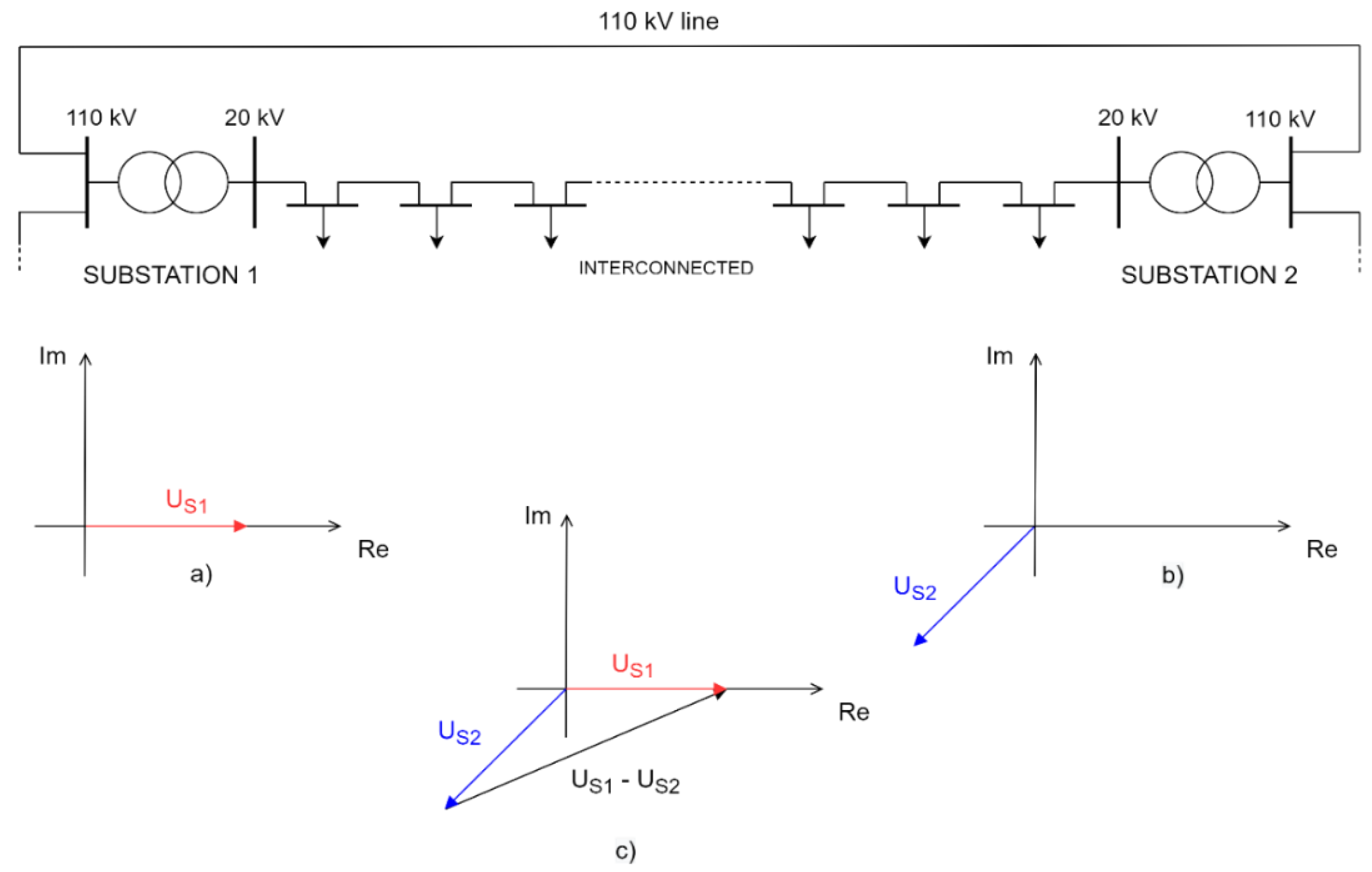
The following situation may occur, which is displayed in
Figure 14, and depicts a MV network fed by two HV/MV substations, connected with a 110 kV line. Substation 1 consists of a HV/MV transformer (usually there are two transformers for redundancy reasons) in a YNyn0 connection, and Substation 2 consists of a HV/MV transformer in a YNd5 connection. It is already obvious that, even in ideal circumstances where both secondary 20 kV voltages are equal in magnitude, their phase angle difference is 30 · 5 = 150°. This results in a situation where voltage difference
between secondary busbars of both feeding substations (displayed in part (c) of
Figure 14) will cause high equalizing currents, and consequentially activate I > protection of one or both feeders.
Even if both observed substations have the same connection type of primary and secondary windings (for example, YNyn0 connection), equalizing currents will still occur, albeit their value will be much lower than in the first case. Nonetheless, in certain situations, they can also cause tripping of the I > protection, provided that the network is in mesh operation. Let us elaborate this problem in more detail. Firstly, primary (and consequentially also secondary) voltages of both substations with the same windings’ connection,
and
, will rarely be in-phase (their phase difference or load angle
being 0°). This is because there is a certain current always flowing through HV lines, as is also the case on a 110 kV line in the example displayed in
Figure 14. Depending on the amount of that current and the impedance of a 110 kV line (or the physical distance between Substations 1 and 2), the voltage drop between these two nodes will vary. As already stated, the voltages on the secondary side of both substations will have the same amounts (RMS values) due to the correct functioning of the AVR system. However, voltage drop between those two nodes will cause a phase angle difference between two voltage phasors,
and
, which is also a crucial parameter for causing equalizing currents.
Let us presume that the shared MV feeder consists of cable lines with a uniform cross-section of 150 mm
2 and has a carrying capacity of 345 A [
66]. Its per unit reactance is 0.2 Ω/km (resistance will be neglected for this assumption), and its total length is 10 km. This aforementioned carrying capacity equals approx. 12 MVA of apparent power on 20 kV voltage, according to the well-known equation
. In addition, let us presume that the total load is equal to 10 MVA (including line and MV/LV transformer losses). At first, the feeder is operating radially. A disconnector switch is opened in a RMU of the MV/LV substation in the middle of the feeder and the load is equally divided amongst the feeding substations (5 MVA each). Since voltages
and
will be now much more aligned than in part (c) of
Figure 14 (due to the same windings’ connection), we will next presume that the aforementioned disconnector switch is closed and the network transitions to mesh operation. If the phase difference between voltages
and
is only 2°, this will cause the additional active and reactive power flows between 20 kV secondary busbars of both feeding substations, according to the following expressions:
In other words, due to a small phase difference , no additional reactive power will flow between 20 kV secondary busbars of both feeding substations. However, the amount of active power flowing due to the same phase difference will be significant. This additional power will have a direction depending on the position of the voltage phasors. If voltage leads ahead of (or lags behind ), the additional power will flow from secondary busbars of Substation 1 towards the secondary busbars of Substation 2. Thus, the first downstream 20 kV line of Substation 1 will carry 5 + 7 = 12 MVA, from which 10 MVA will be consumed on the feeder in order to cover the total load and losses, while 2 MVA will flow through the transformer of Substation 2 and upstream towards the 110 kV network. It is obvious that for 2° of voltage phase difference between adjacent nodes on a 110 kV network, meshed 20 kV distribution network operation results in the maximum capacity of a 150 mm2 cable line being reached. It is important to distinguish that the feeder is not fully loaded since its total load and losses amount to 10 MVA. In the case that the feeder was loaded more (cable carrying capacity of 12 MVA being the limit), meshed operation under these circumstances would definitely cause the tripping of I > protection.
In other words, mesh operation in a topologically interconnected distribution network highly depends on the state of HV network’s node voltages and their phase difference. When radially operated, this particular dependence is completely mitigated and I > protection of a MV distribution network will trip only due to abnormally increased load or a short-circuit.
Meshed operation, however, will cause no aforementioned problems in a topologically closed loop (or ring) network. This is because, as displayed in
Figure 11, a ring network is fed from the same MV busbars, meaning that there will be only one voltage phasor. The voltages on both sides of an opened switch disconnector on a tie-line will have a negligible phase difference
, and thus a distribution network planner and operator will not have to worry about equalizing currents when closing the aforementioned switch disconnector.
As a conclusion, the goal of the authors in their future research will be to conduct an OCR optimization on a topologically closed loop MV distribution network in mesh operation, containing one or more DG units. A general example of this network is displayed in
Figure 15.
Directional relays must be used for optimization problem solving, since meshed operation implies by default that the maximum number of consumers (loads) will have a continuous supply of electrical energy (excluding the lateral lines). Thus, relays closest to the faulted element (line) must trip first. Of course, when implemented in an optimization algorithm, directional relays and primary/backup relays for the observed network will have to be specified in advance as input parameters, prior to algorithm execution.
Finally, in the following chapter, a relatively new concept will be investigated, and it concerns the application of adaptive protection for distribution networks. In this way, all the previous chapters will be appropriately concluded by this advanced protection philosophy, which encompasses all mentioned statements and observations, providing an outlook for the future development of distribution networks.


