
Design of a More Efficient Rotating-EM Energy Floor with Lead-Screw and Clutch Mechanism

 ,
,
Abstract
:1. Introduction
2. Conceptual Design
3. Modeling and Analysis
3.1. Governing Equations
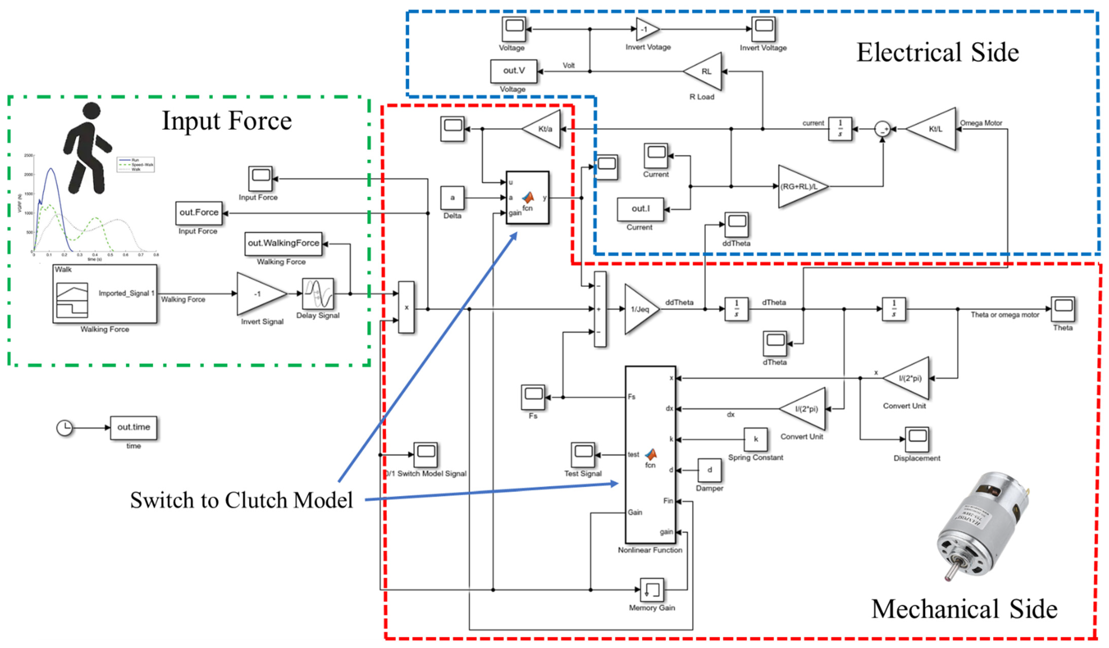
3.2. Simulink Model of the Harvesting System with Clutch Design
3.3. Design of Parameters
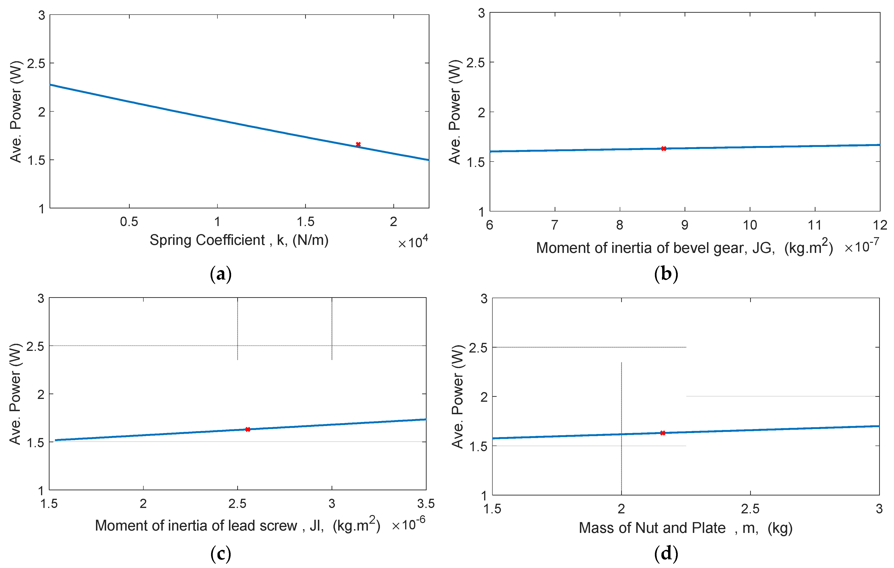
3.3.1. Stiffness Coefficient of Spring and Inertias
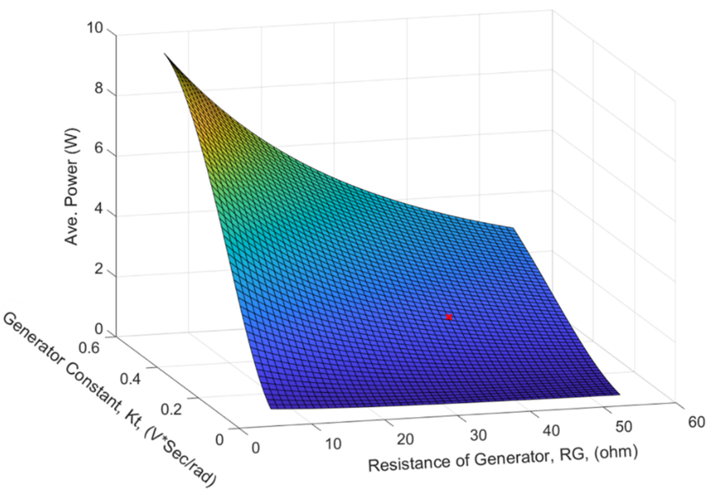
3.3.2. RG and Kt
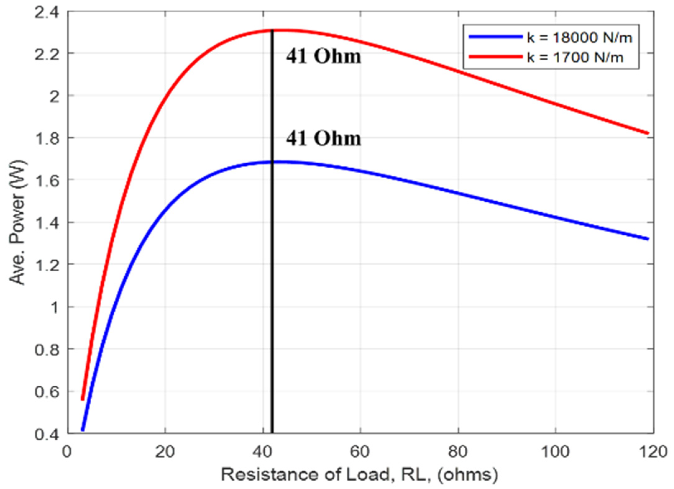
3.3.3. Optimized Resistive Load RL
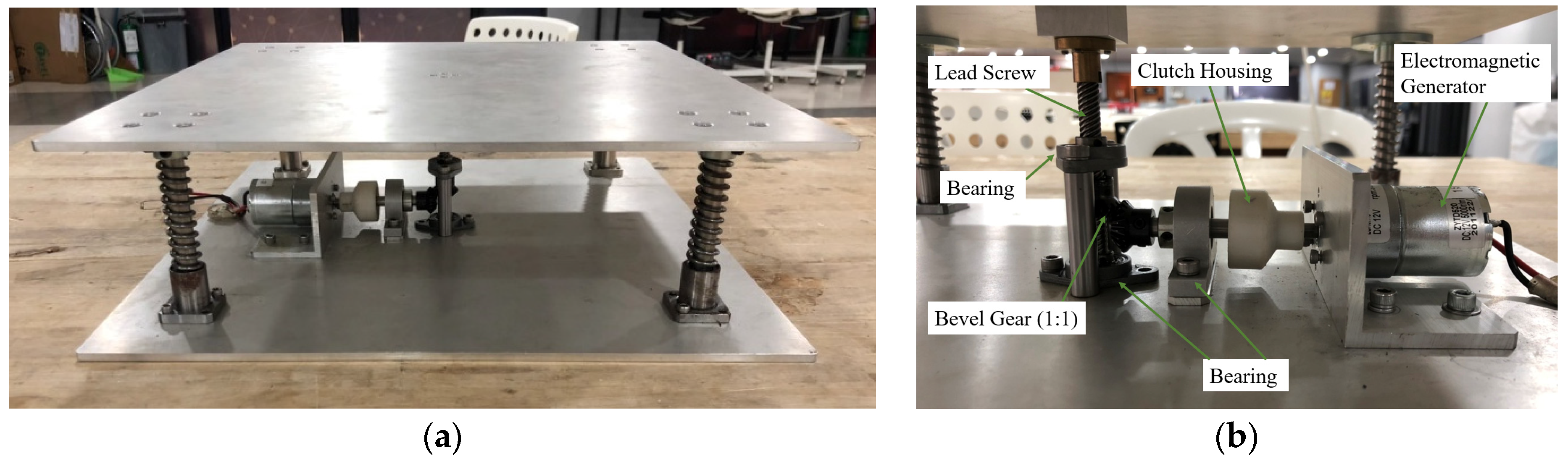
4. Prototype and Test Results
5. Power Management System
6. Installation and Exhibition
7. Conclusions
Author Contributions
Funding
Informed Consent Statement
Data Availability Statement
Acknowledgments
Conflicts of Interest
References
- Pérez, L.; Rodríguez-Jiménez, S.; Rodríguez, N.; Usamentiaga, R.; García, D.F. Digital Twin and Virtual Reality Based Methodology for Multi-Robot Manufacturing Cell Commissioning. Appl. Sci. 2020, 10, 3633. [Google Scholar] [CrossRef]
- Liu, M.; Fang, S.; Dong, H.; Xu, C. Review of digital twin about concepts, technologies, and industrial applications. J. Manuf. Syst. 2021, 58, 346–361. [Google Scholar] [CrossRef]
- Vocca, H.; Cottone, F. Kinetic energy harvesting. In ICT-Energy-Concepts Towards Zero-Power Information and Communication Technology; IntechOpen: London, UK, 2014. [Google Scholar] [CrossRef]
- Hasan, M. State of IoT 2022: Number of connected IoT devices growing 18% to 14.4 billion globally. IOT Anal. Mark. Insights Internet Things 2022. Available online: https://iot-analytics.com/number-connected-iot-devices/ (accessed on 31 July 2022).
- Shah, A.S.; Nasir, H.; Fayaz, M.; Lajis, A.; Shah, A. A review on energy consumption optimization techniques in IoT based smart building environments. Information 2019, 10, 108. [Google Scholar] [CrossRef]
- Chalasani, S.; Conrad, J.M. A survey of energy harvesting sources for embedded systems. In Proceedings of the IEEE SoutheastCon 2008, Huntsville, AL, USA, 3–6 April 2008; pp. 442–447. [Google Scholar] [CrossRef]
- Akinaga, H. Recent advances and future prospects in energy harvesting technologies. Jpn. J. Appl. Phys. 2020, 59, 110201. [Google Scholar] [CrossRef]
- Jayakumar, H.; Lee, K.; Lee, W.S.; Raha, A.; Kim, Y.; Raghunathan, V. Powering the internet of things. In Proceedings of the 2014 International Symposium on Low Power Electronics and Design, La Jolla, CA, USA, 11–13 August 2014; pp. 375–380. [Google Scholar]
- Elahi, H.; Munir, K.; Eugeni, M.; Atek, S.; Gaudenzi, P. Energy harvesting towards self-powered IoT devices. Energies 2020, 13, 5528. [Google Scholar] [CrossRef]
- Dinulovic, D.; Brooks, M.; Haug, M.; Petrovic, T. Rotational electromagnetic energy harvesting system. Phys. Procedia 2015, 75, 1244–1251. [Google Scholar] [CrossRef]
- Weimer, M.A.; Paing, T.S.; Zane, R.A. Remote area wind energy harvesting for low-power autonomous sensors. In Proceedings of the 2006 37th IEEE Power Electronics Specialists Conference, Jeju, Korea, 18–22 June 2006; pp. 1–5. [Google Scholar]
- Alippi, C.; Galperti, C. An adaptive system for optimal solar energy harvesting in wireless sensor network nodes. IEEE Trans. Circuits Syst. I Regul. Pap. 2008, 55, 1742–1750. [Google Scholar] [CrossRef]
- Wei, X.; Zhao, Z.; Wang, L.; Jin, X.; Yuan, Z.; Wu, Z.; Lin Wang, Z. Energy conversion system based on Curie effect and triboelectric nanogenerator for low-grade heat energy harvesting. Nano Energy 2022, 91, 106652. [Google Scholar] [CrossRef]
- Jin, X.; Yuan, Z.; Shi, Y.; Sun, Y.; Li, R.; Chen, J.; Wang, L.; Wu, Z.; Lin Wang, Z. Triboelectric Nanogenerator Based on a Rotational Magnetic Ball for Harvesting Transmission Line Magnetic Energy. Adv. Funct. Mater. 2022, 32, 2108827. [Google Scholar] [CrossRef]
- Wu, Z.; Guo, H.; Ding, W.; Wang, Y.; Zhang, L.; Lin Wang, Z. A Hybridized Triboelectric–Electromagnetic Water Wave Energy Harvester Based on a Magnetic Sphere. ACS Nano 2019, 13, 2349–2356. [Google Scholar] [CrossRef] [PubMed]
- Brunner, S.; Gerst, M.; Pylatiuk, C. Design of a body energy harvesting system for the upper extremity. Curr. Dir. Biomed. Eng. 2017, 3, 331–334. [Google Scholar] [CrossRef]
- Choi, Y.M.; Lee, M.G.; Jeon, Y. Wearable biomechanical energy harvesting technologies. Energies 2017, 10, 1483. [Google Scholar] [CrossRef]
- Beeby, S.P.; Torah, R.N.; Tudor, M.J.; Glynne-Jones, P.; O’Donnell, T.; Saha, C.R.; Roy, S. A Micro Electromagnetic Generator for Vibration Energy Harvesting. J. Micromech. Microeng. 2007, 17, 1257–1265. [Google Scholar] [CrossRef]
- Bassett Jr, D.R.; Wyatt, H.R.; Thompson, H.; Peters, J.C.; Hill, J.O. Pedometer-measured physical activity and health behaviors in United States adults. Med. Sci. Sports Exerc. 2010, 42, 1819. [Google Scholar] [CrossRef] [PubMed]
- World Population Prospects 2019. Available online: https://population.un.org/wpp/ (accessed on 31 July 2022).
- Riemer, R.; Shapiro, A. Biomechanical Energy Harvesting from Human Motion: Theory, State of the Art, Design Guidelines, and Future Directions. J. Neuroeng. Rehab. 2011, 8, 22. [Google Scholar] [CrossRef]
- Energy Floors 2022. Available online: https://energy-floors.com (accessed on 31 July 2022).
- Pavegen 2022. Available online: https://pavegen.com/ (accessed on 31 July 2022).
- Jintanawan, T.; Phanomchoeng, G.; Suwankawin, S.; Kreepoke, P.; Chetchatree, P.; U-viengchai, C. Design of Kinetic-Energy Harvesting Floors. Energies 2020, 13, 5419. [Google Scholar] [CrossRef]
- Lowattanamart, W.; Suttisung, V.; Sintragoonchai, S.; Phanomchoeng, G.; Jintanawan, T. Feasibility on development of kinetic-energy harvesting floors. In IOP Conference Series: Earth and Environmental Science; IOP Publishing: Bristol, UK, 2020; Volume 463, p. 012107. [Google Scholar]
- Liu, M.; Lin, R.; Zhou, S.; Yu, Y.; Ishida, A.; McGrath, M.; Kennedy, B.; Hajj, M.; Zuo, L. Design, Simulation and Experiment of a Novel High Efficiency Energy Harvesting Paver. Appl. Energy 2018, 212, 966–975. [Google Scholar] [CrossRef]
- The MathWorks Inc., Matlab. Available online: https://www.mathworks.com (accessed on 23 April 2022).
- Stephen, N.G. On Energy Harvesting from Ambient Vibration. J. Sound Vib. 2006, 1–2, 409–425. [Google Scholar] [CrossRef] [Green Version]


| Parameters | Value |
|---|---|
| Pitch of Lead Screw (l) | 8 mm |
| Mass of Nut and Plate (m) | 2.16 kg |
| Moment of Inertia of lead screw (Jl) | 2.5536 × 10⁻⁶ kg·m2 |
| Moment of inertia of bevel gear (JG) | 8.6750 × 10⁻⁷ kg·m2 |
| Lead angle | 30 degrees |
| Spring Coefficient (k) | 18,000 N/m |
| Damping Coefficient (d) | 11,000 N·s/m |
| Resistance of Generator (RG) | 37 Ohm |
| Inductance (L) | 3.6 × 10⁻³ H |
| Generator constant (Kt) | 0.2903 Vs/rad |
| Resistance of Load (RL) | 30 Ohm |
| Friction coefficient (µ) | 0.21 |
| Efficient of thrust bearing ηthrust | 0.8101 |
| Efficient of thread ηthread | 0.6444 |
| Experiment | Simulation with Half-Sine Wave Force | Simulation with Normal Walking Force | |
|---|---|---|---|
| Variables | Values per Footstep | Values per Footstep | Values per Footstep |
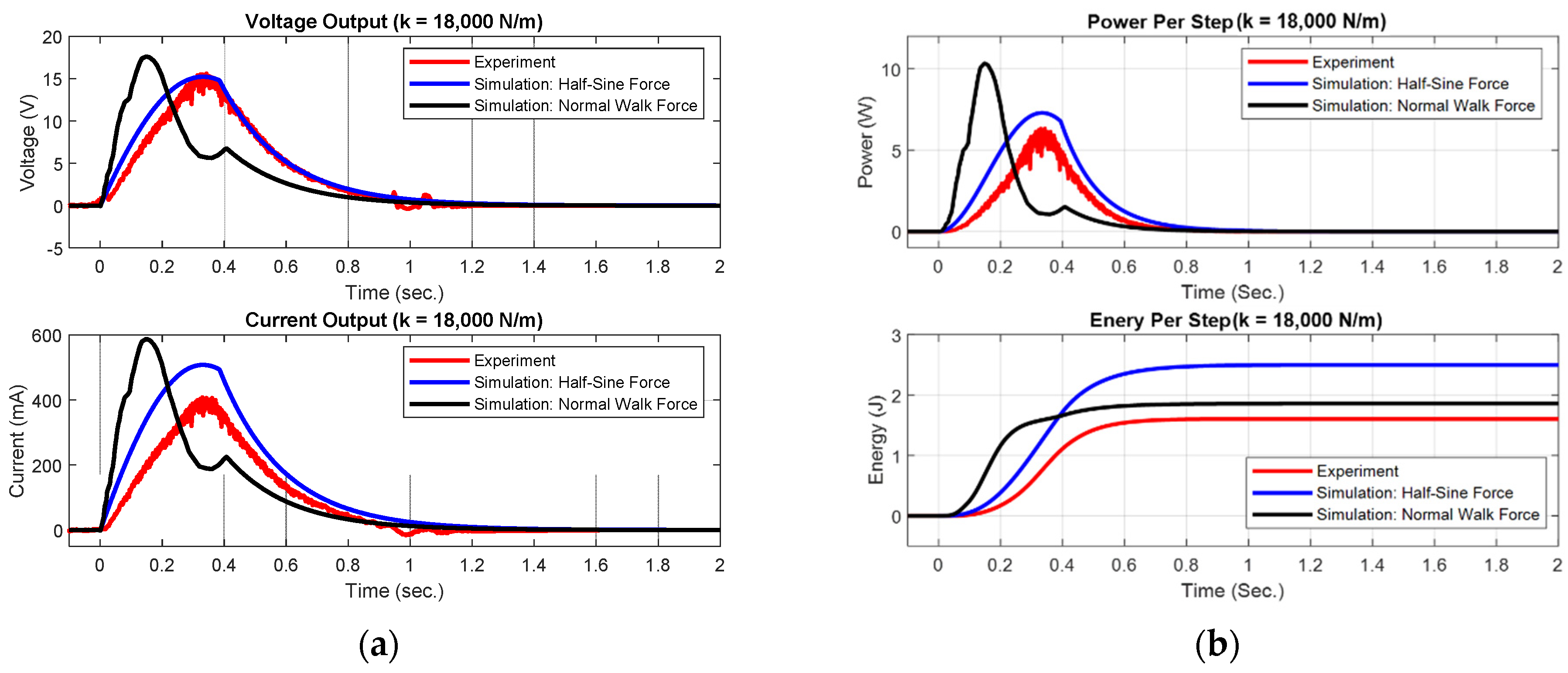
| Maximum voltage | 15.60 V | 14.80 V | 17.61 V |
| Average voltage | 6.11 V | 5.58 V | 4.24 V |
| Maximum current | 408.0 mA | 493.1 mA | 587.1 mA |
| Average current | 154.4 mA | 186.0 mA | 141.2 mA |
| Maximum power | 6.33 W | 7.30 W | 10.34 W |
| Average power | 1572 mW | 1853 mW | 1377 mW |
| Wave duration | 1.02 s | 1.35 s | 1.35 s |
| Average energy | 1603 mJ | 2501 mJ | 1859 mJ |
| Genpath V1 Simulation with Half-Sine Wave Force | Genpath V2 Simulation with Half-Sine Wave Force | |
|---|---|---|
| Variables | Values per Footstep | Values per Footstep |
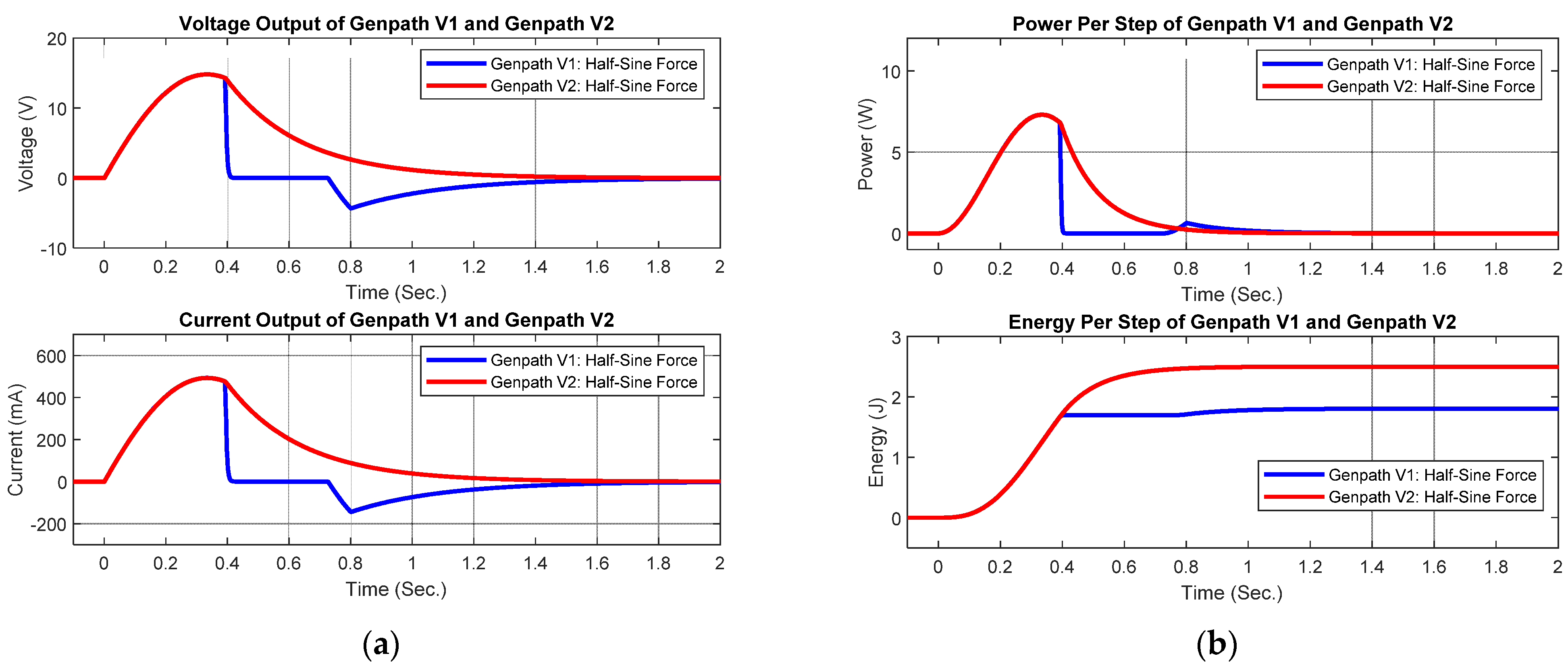
| Maximum voltage | 14.78 V | 14.78 V |
| Average voltage | 1.93 V | 5.377 V |
| Maximum current | 493.2 mA | 493.1 mA |
| Average current | 64.3 mA | 179.2 mA |
| Maximum power | 7.30 W | 7.30 W |
| Average power | 1289 mW | 1786 mW |
| Wave duration | 1.40 s | 1.40 s |
| Average energy | 1804 mJ | 2501 mJ |
| Decrease 20% | Decrease 10% | Normal Value | Increase 10% | Increase 20% | |
|---|---|---|---|---|---|
| Spring Coefficient (k) N/m | 14,400 | 16,200 | 18,000 | 19,800 | 21,600 |
| Power (W) | 1.751 | 1.69 | 1.6297 | 1.568 | 1.5113 |
| % Power Increase/Decrease | +7.44% | +3.70% | 0.00% | −3.79% | −7.27% |
| Moment of inertia of bevel gear (JG) kg·m2 | 6.9400 × 10⁻⁷ | 7.8075 × 10⁻⁷ | 8.6750 × 10⁻⁷ | 9.5425 × 10⁻⁷ | 10.4100 × 10⁻⁷ |
| Power (W) | 1.6107 | 1.6202 | 1.6297 | 1.6392 | 1.6487 |
| % Power Increase/Decrease | −1.16% | −0.58% | 0.00% | +0.58% | +1.17% |
| Moment of Inertia of lead screw (Jl) kg·m2 | 2.0428 × 10⁻⁶ | 2.2982 × 10⁻⁶ | 2.5536 × 10⁻⁶ | 2.8089 × 10⁻⁶ | 3.0640 × 10⁻⁶ |
| Power (W) | 1.5737 | 1.6018 | 1.6297 | 1.6577 | 1.6858 |
| % Power Increase/Decrease | −3.44% | −1.71% | 0.00% | +1.72% | +3.44% |
| Mass of Nut and Plate (m) kg | 1.728 | 1.944 | 2.16 | 2.376 | 2.592 |
| Power (W) | 1.5940 | 1.6119 | 1.6297 | 1.6476 | 1.6654 |
| % Power Increase/Decrease | −2.19% | −1.09% | 0.00% | +1.10% | +2.19% |
| Genpath V2 | ||
|---|---|---|
| Item | Dimensions | Number |
| Wood plate | 400 × 400 × 5 mm | 2 |
| Linear guide | Diameter 12 mm Length 90 mm | 4 |
| Linear bearing | Inner diameter 12 mm | 4 |
| Shaft coupling | Inner diameter 12 mm | 4 |
| Coil spring * | Length 60 mm Diameter 2.2 mm | 4 |
| Shaft to generator | Diameter 8 mm Length 60 mm | 1 |
| Nut and lead screw | Diameter 8 mm Pitch 2 mm | 1 |
| Flexible coupling | 8 mm | 1 |
| Bevel gear | Inner diameter 8 mm | 2 |
| Ball bearing | Inner diameter 8 mm | 3 |
| Clutch | CSK8 PP | 1 |
| Housing | 22 × 32 × 29 mm | 1 |
| Generator | ZGA37RG 12V 300 rpm | 1 |
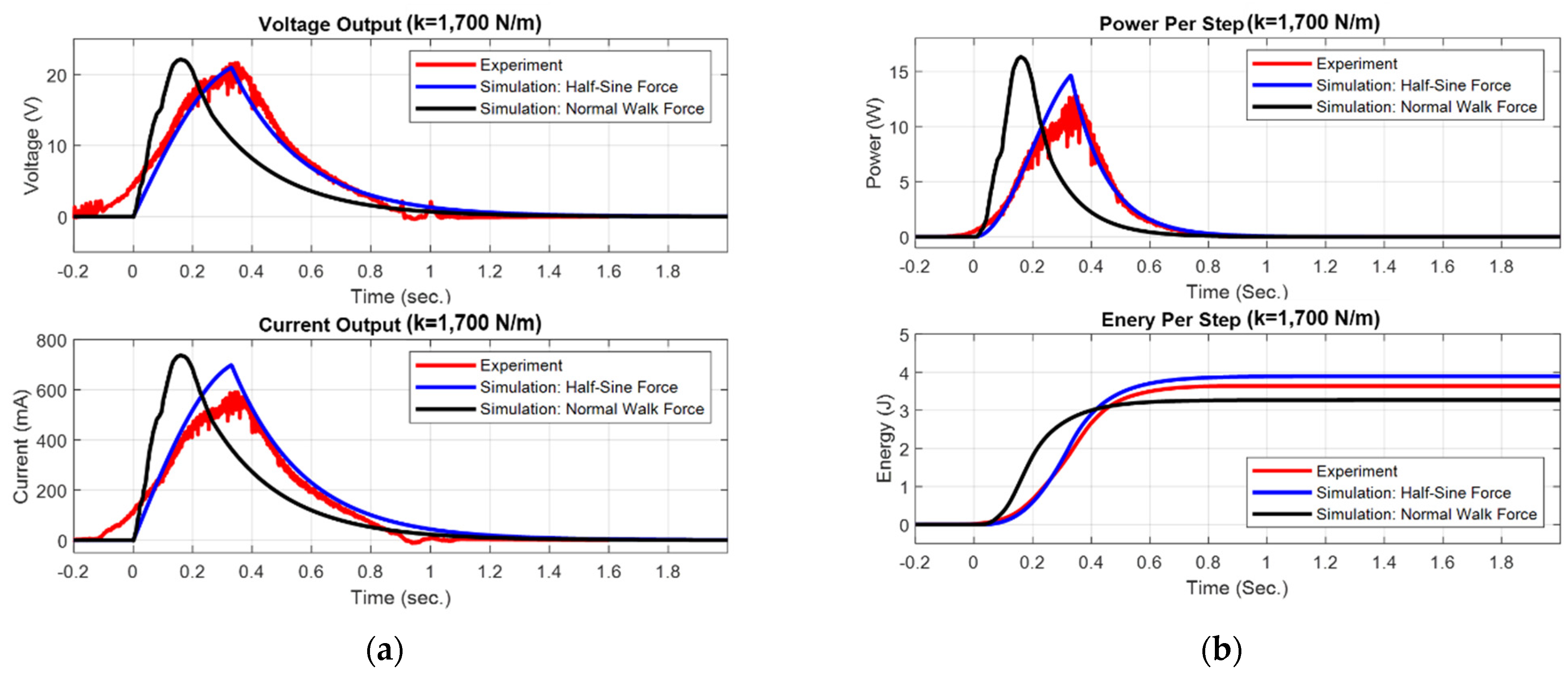
| Variables | Genpath V1 | Genpath V2 | Genpath V2 | Genpath V2 |
|---|---|---|---|---|
| Experiment | Experiment | Simulation with Half-Sine Wave Force | Simulation with Normal Walking Force | |
| Values per Footstep | Values per Footstep | Values per Footstep | Values per Footstep | |
| Maximum voltage | 9.5 V | 21.60 V | 20.95 V | 22.12 V |
| Average voltage | 2.88 V | 8.59 V | 6.53 V | 5.376 V |
| Maximum current | 285 mA | 590 mA | 698.2 mA | 737.2 mA |
| Average current | 88 mA | 231.1 mA | 217.8 mA | 179.2 mA |
| Maximum power | 2.71 W | 12.74 W | 14.62 W | 16.31 W |
| Average power | 520 mW | 3219 mW | 2782 mW | 2335 mW |
| Wave duration | 1.35 s | 1.13 s | 1.40 s | 1.40 s |
| Average energy | 702 mJ | 3637 mJ | 3895 mJ | 3269 mJ |
Publisher’s Note: MDPI stays neutral with regard to jurisdictional claims in published maps and institutional affiliations. |
© 2022 by the authors. Licensee MDPI, Basel, Switzerland. This article is an open access article distributed under the terms and conditions of the Creative Commons Attribution (CC BY) license (https://creativecommons.org/licenses/by/4.0/).
Share and Cite
Jintanawan, T.; Phanomchoeng, G.; Suwankawin, S.; Thamwiphat, W.; Khunkiat, V.; Watanasiri, W. Design of a More Efficient Rotating-EM Energy Floor with Lead-Screw and Clutch Mechanism. Energies 2022, 15, 6539. https://doi.org/10.3390/en15186539
Jintanawan T, Phanomchoeng G, Suwankawin S, Thamwiphat W, Khunkiat V, Watanasiri W. Design of a More Efficient Rotating-EM Energy Floor with Lead-Screw and Clutch Mechanism. Energies. 2022; 15(18):6539. https://doi.org/10.3390/en15186539
Chicago/Turabian StyleJintanawan, Thitima, Gridsada Phanomchoeng, Surapong Suwankawin, Weeraphat Thamwiphat, Varinthorn Khunkiat, and Wasu Watanasiri. 2022. "Design of a More Efficient Rotating-EM Energy Floor with Lead-Screw and Clutch Mechanism" Energies 15, no. 18: 6539. https://doi.org/10.3390/en15186539