1. Introduction
Due to their high power density, power factor, and high efficiency, permanent magnet synchronous motors (PMSMs) are widely used in electric vehicles, industrial robotics, and aerospace [
1]. The classic double closed-loop system of PMSMs has a complex structure and several loops that restrict the system dynamic performance. As a result, a non-cascaded structure with a simple control design (simultaneous current and speed control) and parameter-tuning is established. However, this structure suffers from current overruns and unmatched disturbances, which have an impact on its dynamic performance. Current overruns not only cause hardware damage, but they also increase needless energy losses [
2,
3]. As a consequence, it is critical to conduct research on control solutions that take into account both current constraints and dynamic performance.
With industrial development, there are higher demands for PMSM controllers [
4]. Recently, many control algorithms have become popular, such as fuzzy control [
5], predictive control [
6], adaptive control [
7], sliding-mode control (SMC) [
8], etc. In [
5], fuzzy control combined with proportional integration is designed to enhance the speed control of pump motors and improve operating efficiency. In [
6], the speed and current can be directly controlled by a differential-free, predictive-current, sliding-mode control strategy for PMSMs. In [
7], the current-loop performance and tracking accuracy of PMSMs are improved by the adaptive internal mode observer. In [
8], adaptive fuzzy sliding-mode control is designed to improve the PMSMs drive-system response for uncertain systems with actuator failures and input saturation. Compared with other control methods, SMC has the advantage of a sliding-mode-specific, independent design, and it is not affected by parameter ingestion, particularly as a consequence of its fast dynamic response, finite-time convergence, and high steady-state accuracy. Non-singular-sliding mode [
9] is widely used in applications that require high-precision control. However, although the above control solutions have addressed the problem of drive-motor speed and current-tracking accuracy, few works consider current constraint.
Overcurrent protection is a problem in a non-cascade control structure for a PMSMs system. In [
10], the traditional PID of selecting control parameters is designed for PMSMs system to achieve current constraint. Unfortunately, it cannot simultaneously achieve overcurrent protection, current dynamic performance, and anti-disturbance capabilities. In [
11], the control mode is transformed into an optimization mode to effectively predict, constrain the current amplitude, and improve the current-control performance. However, this control strategy is implemented indirectly. In [
12], the complete-state constraint is implemented by a new, recursive design approach. However, its parameter selection is conservative, and the virtual controller is restricted. In [
13], the model predictive control method is designed for PMSMs such that the computational effort of the speed-predictive control can be reduced. However, its current-constraint can only be implemented by setting the upper limit of the
q-axis current. In [
14], a combined velocity and thrust strategy based on sliding-mode control is proposed to improve the speed and current dynamic performance. However, this strategy contains integrals that cause performance coupling and negatively affect parameter-tuning. In [
15], the state-dependent Riccati equation is designed for PMSM speed control to satisfy the constrained maximum current amplitude. However, this strategy require huge computational resources. In addition, few works have considered control solutions to address unmatched disturbances.
Recently, many observers have been designed in PMSMs system to improve the disturbance-rejection ability, such as sliding-mode observers [
16,
17,
18], nonlinear observers [
19], extended-state observers [
20,
21], and intelligent-disturbance observers [
22]. In [
16], under the matched-disturbances condition, an adaptive sliding-mode observer is designed to improve the anti-disturbance capability of the PMSMs drive system. Specially, fewer investigations have been conducted for mismatch perturbations (external load torque or unmodeled dynamics). Such disturbances increase the difficulty of motor control. The above observers are partially used to address the unmatched disturbances. In [
17], the integral sliding-mode disturbance observer is used for continuous-time linear systems with unmatched disturbances or uncertainties. However, the integral sliding-mode strategy suffers from overshoot. In [
18], under-matched and unmatched disturbances conditions, continuous-terminal sliding-mode control, and single-loop velocity-current control with disturbance observers are designed to improve the speed-regulation performance of PMSMs. However, the sliding-mode control strategy is fully robust for matched disturbances, and the design is partially avoidable. In [
19], the disturbances are integrated into the sliding surface, and a nonlinear disturbance observer is used to solve the five-phase PMSM’s unmatched disturbances. In [
23], a controller is designed to solve the current-overrun problem caused by mismatched disturbances. The speed-control part of this control strategy is similar to the PID idea and forms a closed-loop with a nonlinear observer. The current-constraint problem is effectively solved. In [
24], a simple overcurrent-protection method is applied to a permanent magnet synchronous motor drive system and discards the traditional method of conservatively estimating parameters. The strategy provides both a fast dynamic response and overcurrent protection. However, the experimental section does not consider cases of frequently changing loads or some other motor-overcurrent scenarios. This method fails to solve the perturbation problem well.
In summary, current-constrained and unmatched disturbances are not considered or addressed in a PMSM drive system. This paper proposes a composite strategy based on a fast non-singular terminal sliding-mode and sliding-mode observer, and it simultaneously tackles current-constrained and unmatched disturbances. The main novelties of this research are summarized as follow:
- (1)
It reconstructs the non-cascade PMSM speed-control equation of the motor system to solve the problems of overcurrent protection and unmatched disturbances. A fast non-singular sliding-mode-based speed-control strategy and the q-axis current by constructing a nonlinear item are proposed so as to fulfill the overcurrent-protection task and effectively guarantee current-constraint, even in the presence of unmatched disturbances.
- (2)
Unmatched disturbances affect the dynamic performance of the system through different channels by designing a disturbance sliding-mode observer to achieve compensation for mismatched disturbances. The modification of the ideal speed-value of the motor is verified by Liapunov’s stability theorem. We design the overcurrent scenario for an overload of the permanent magnet synchronous motor and perform the disturbance compensation and overcurrent protection by FNTSM-SMDO. The FNTSM-SMDO can satisfy the need for a fast and robust system simultaneously, and the effectiveness of the method is verified by two sets of PI-control comparison experiments.
2. FNTSM Design for PMSM Speed Controller
2.1. The Mathematical Model of PMSM
The mathematical model of a surface-mounted PMSM in the
d-q frame is formulated as
where
,
are the voltages of the
-axes,
,
are the stator current,
is the inductance of the stator,
is the number of pole pairs,
is the flux linkage,
R is the stator resistance, and
is the angular velocity.
The torque equation of a surface-mounted PMSM is
The motion equation of a surface-mounted PMSM is
where
is the torque,
is the load torque of the motor,
J is the moment of inertia, and
B is the viscous frictional coefficient.
System (1) can be transformed with
Setting the d-axis reference current
, enables obtaining the maximum torque-to-current ratio. System (1) can be rewritten as
Suppose that the current iq is bounded by a constant c > 0, which is a safety threshold and often selected as times of the rated current in industrial applications. Since the load-torque variations influence the current directly, a load-torque change may violate the current constraint. It can cause damage to the battery, inverter, and other hardware in serious cases.
2.2. Control-Oriented Model
The model-control objective is mainly the speed-tracking of a given reference signal and achieving current-constraint under unmatched disturbances by defining as the speed-tracking error and as the system state, where is the reference speed.
Therefore, the control-oriented model is written as
where
is the control input,
,
.
In this way, the current constraint is , equivalent to the state constraint . The control problem is transformed to stabilize e1 in the presence of the state constraint e2 and the unmatched disturbance d.
The fast non-singular terminal sliding-mode control strategy is chosen for the PMSMs system. When the system state slides to the designed sliding surface, it quickly reaches the balance point. It improves the arrival time for states far from the balance point when using the terminal sliding mode. The sliding surface is selected as follows:
Then, the derivative of Equation (7) is
Combining System (6) and Equation (8),
Defining
,
,
as a variable for the simplification of Equation (9). Therefore, Equation (9) can be rewritten as
The improved, variable exponential-reaching law researched by our research group can realize the adaptive adjustment of the approach speed. The specific proof is in [
25].
It is supposed that
d has a constant steady-state value. We design a low-pass filter as follows:
We define , where is the speed-error estimation; is the disturbance estimation.
To satisfy the current-constraint, it is crucial to constitute the constraint mechanism of the nonlinear item on the q-axis current in the control strategy. If tends to the limit , i.e., the state tends to the limit boundary or , then the function will tend to infinity. Thus, the nonlinear item can be automatically adjusted.
3. Design of the SMDO
The SMDO is designed to address unmatched disturbances, such as parameters and external disturbances. It can simultaneously observe torque disturbances and motor speed, which can reduce system chattering. To acquire the estimation value
of the unmatched disturbance
d in System (6), the SMDO is designed as
where
k1 > 0 is the observer gain.
We define the input to the observer as
To verify that System (13) and Equation (7) can effectively estimate the system error and achieve the fast-tracking of the ideal speed, the Lyapunov stability function can be described as.
Then, the derivative of Equation (15) is
Combining Equations (14) and (16), we can obtain that
. From Lyapunov’s stability theorem,
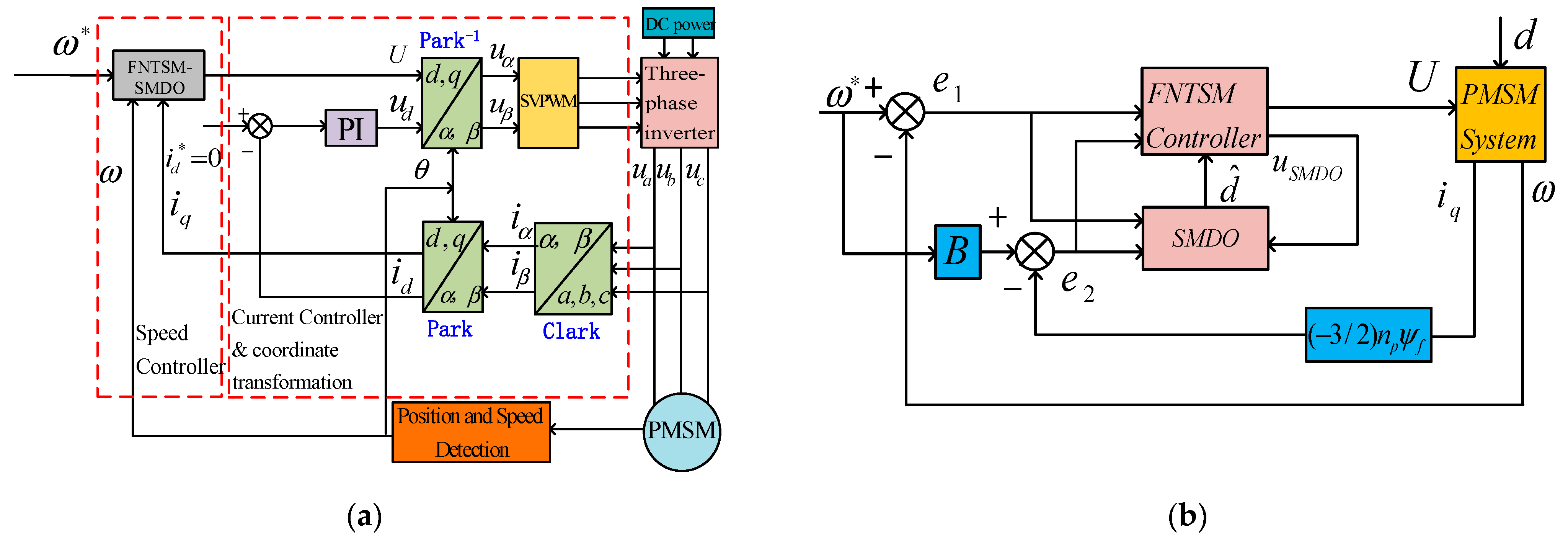
ensures the stability of the designed FNTSM–SMDO in terms of tracking error, and it achieves reaching in finite time to achieve the reference speed. The PMSM drive-framework based on the proposed strategy is shown in
Figure 1 to better illustrate the structure of the proposed controller.
4. Experimental Tests Results
The composite strategy is verified by comprehensive experiments. This paper demonstrates the speed and current-response performance of the PMSM drive system in such typical situations as start-up response, variable acceleration, unmatched disturbances, and overload process. The unmatched disturbances are presented in
Figure 2. Where 0.3 s~1 s is sawtooth form, 1 s~2 s is a sinusoidal form expressed as
, and 2 s~3 s is a constant value expressed as
TL = 2 Nm. The parameters of the motor are presented in
Table 1.
To verify the effectiveness of the method proposed in this paper, an xPC-Target-based hardware-in-the-loop testbed was built, as shown in
Figure 3. The testbed includes two industrial control machines, motors, and controllers. One of the IPCs was used as the host PC and equipped with the PMSM-control algorithm. A Simulink model was compiled into real-time operational C code and downloaded to the target PC. Another IPC was used as the xPC-target PC, running DOS-dependent xPC real-time cores to execute RTW-compiled real-time C code. The two PCs were connected and communicated through TCP/IP, and the developer downloaded the Simulink model to the target PC through the host PC. The two PCs could monitor/debug the operation of the target PC in real time. The parameters of the controller are presented in
Table 2.
4.1. Variable Acceleration Process
We compared the starting speed and current dynamic performance of PMSM under various control strategies.
Figure 4a,b shows the motor-speed and
q-axis current-response curves during the start-up transient based on FNTSM–SMDO, PI(low) and PI(high) control, starting at 1000 RPM, accelerating to 1500 RPM at 1 s, and accelerating to 2000 RPM at 2 s, respectively. This variable accelerates the process with a load of 1 Nm.
A traditional double closed-loop PI control strategy was used for the comparison experiments, with the following details.
Current loop:
where
,
are the scale and integration coefficients of the speed loop, and
,
are the scale and integration coefficients of the current loop. In the experiment, the PI(low) parameters are as follow:
,
,
, and
. The PI(high) parameters are as follow:
,
,
, and
.
In order to make the experimental results comparable, the operating curves of the FNTSM–SMDO, PI(low) and PI(high) control methods are trended close to each other during the start-up of the PMSM. The following conclusions can be drawn from
Figure 4a,b: PI(high) has a large overshoot; FNTSM–SMDO and PI(low) control methods start without overshoot. Because the FNTSM–SMDO contains the terminal sliding-mode term and the speed-error term in the reaching law, the FNTSM–SMDO reaches the reference speed quickly in each stage. The coefficient of the scaling term in PI(high) is too large, causing a 20% overshoot in each section during acceleration. When the speed is 1000 RPM, the stabilization time of the FNTSM–SMDO is 0.04 s, and that of the PI(low) and PI(high) control method is 0.12 s; when accelerating to 1500 RPM, the stabilization time of the FNTSM–SMDO is 1.08 s, and that of the PI(low) and PI(high) control method is 1.12 s; when continuing to accelerate to 2000 RPM, the stabilization time of the FNTSM–SMDO is 2.06 s, and the stabilization time of the PI(low) and PI(high) control method is 2.12 s. When the acceleration is continued to 2000 RPM, the stabilization time of the FNTSM–SMDO is 2.06 s.
The start of the PMSM generates iq peak current, and it is too large to cause fatal damage to the device. Therefore, the key nonlinear terms in the FNTSM–SMDO play a key role. When the PMSM is in the process of starting and accelerating, the peak current can be suppressed below 10A, which effectively protects the motor from the influence of the sudden peak current. However, the iq amplitude of the PI control is over the current constraint, which may break down the hardware device.
4.2. Unmatched Disturbance Process
We compared the starting-speed and current-dynamic performance of the PMSM under various control strategies.
Figure 5a,b shows the motor-speed and
q-axis current-response curves during the start-up transient based on the FNTSM–SMDO and PI(low) and PI(high) control, starting at 1000 RPM under conditions of unmatched disturbances.
The stabilization time is obtained as shown in
Figure 4a, so this part of the experimental data focuses on the comparison of the recovery time and speed drop. When the PMSM encounters the mismatched disturbance simulated in
Figure 2, an analysis of
Figure 5a leads to the following conclusions: when 0.2 s~1 s encounters a sawtooth-wave load, the sliding-mode control part in the FNTSM–SMDO plays a key role, and the robustness of the sliding-mode control is better than that of the PI control, so the recovery time of the FNTSM–SMDO is 0.38 s, and the speed drop is 37 RPM. The recovery time of the PI(low) control is 0.8 s, and the speed drops 58 RPM. When the PMSM encounters a sinusoidal disturbance in 1 s~2 s, the speed does not fully recover due to the sawtooth-wave load in the previous section, so the speed of the PI(low) control drops 130 RPM during the sinusoidal disturbance; the speed of the FNTSM–SMDO drops 25 RPM and quickly recovers the reference speed. In this stage, the load changes frequently, i.e., the load increases and decreases suddenly, which tests the robustness of the control strategy. When 2 s~3 s, this stage is a typical, fixed-load perturbation, where the load suddenly decreases abruptly, the PI control-speed changes very obviously, and the recovery time is very long. The rising speed of the FNTSM–SMDO is 9 RPM, and the recovery time is 0.1 s; the rising speed of PI(low) control is 40 RPM, and the recovery time is 0.92 s. The main reason for this phenomenon is that the load changes continuously and frequently, which causes the PI-control fail to respond to each section in time, and the slow response speed leads to the poor dynamic performance of the PMSM. The excessive overshoot in the PI(high) results in a fast speed-recovery under each section of the disturbance. This does not affect the control performance of the FNTSM–SMDO because PI control cannot balance good dynamic and static characteristics.
4.3. Overload Process
In the overcurrent scenario of the PMSM, in addition to peak-current overrun, overload can also lead to current overrun. Therefore, this part simulates the overload process; when the PMSM runs up to 2 s, the load suddenly changes from no load to 150% of the rated load. The rated torque of the PMSM used in this paper is 10 Nm, so an overload of 150% means the load is 15 Nm. We compared the starting speed and current dynamic performance of the PMSM under various control strategies.
Figure 6a,b shows the motor speed and
q-axis current-response curves during the start-up transient based on the FNTSM-SMDO, the PI(low), and the PI(high) controls using the method of starting at 1000 RPM under the overload process.
This section simply summarizes the experimental results without too much explanation.
Section 4.1 and
Section 4.2 explained the algorithm in detail. When the speed is 1000 RPM with a load of 15 Nm, the FNTSM–SMDO speed drops 250 RPM, with a recovery time of 0.15 s; the PI(low) control speed drops 800 RPM, with a recovery time of 1 s; and the PI(high) control speed drops 50 RPM, with a recovery time of 0.1 s. The main point of this section is that the overcurrent caused by the overload is well suppressed.
When the PMSM encounters an overload situation, the amplitude of the iq current is even greater, threatening the safety of the equipment. In this case, the amplitude of iq under PI control is close to the peak current, but under the FNTSM–SMDO control, it is well-suppressed.


