Article

Development and Tests of the Solar Air Heater with Thermal Energy Storage

by
Krzysztof Sornek
* and
Karolina Papis-Frączek
Department of Sustainable Energy Development, Faculty of Energy and Fuels, AGH University of Science and Technology, Mickiewicza Ave. 30, 30-059 Krakow, Poland
*
Author to whom correspondence should be addressed.
Energies 2022, 15(18), 6583; https://doi.org/10.3390/en15186583
Submission received: 22 August 2022 / Revised: 2 September 2022 / Accepted: 5 September 2022 / Published: 8 September 2022
(This article belongs to the Special Issue Research in Building Physics and Renewable Energy)

Abstract

:
Passive solutions in buildings have recently been rediscovered because they allow the rational use of solar radiation, which promotes energy savings. Thermal energy gained from the sun may be stored in the form of sensible heat in accumulative solid materials in a building envelope. This paper proposes an innovative solar air heater that captures and accumulates solar energy during the day and releases it during the night. The analyzed system is based on inexpensive ceramic modules, which can be used to construct thermal storage walls or solar chimneys in modern buildings. Both configurations have been tested experimentally and by a numerical model in ArCADia BIM software. Experiments have been carried out in laboratory conditions using a specially developed prototype. Among other parameters, power transferred from the solar air heater to the ventilation air in different conditions has been analyzed. When airflow was set to 150 m3/h, the maximum power observed under stable working conditions was approx. 355.0 W when the developed solar air heater operated as the solar chimney, and approx. 165.0 W when it operated as the solar thermal wall. When airflow was set to 200 m3/h, the maximum power was approx. 385.0 W. Experimental results have been used to calculate the efficiency of the solar air heater in real conditions. The total efficiency in the case of the solar chimney was estimated as 0.25, while in the case of the thermal wall it was estimated as 0.78, which resulted in an annual reduction in energy usage at a level of 190.7 kWh and 556.1 kWh, respectively (4.8 and 14.0%). In practice, these values can be significantly higher due to the possibility of increasing the length and shape of the accumulation heat exchanger.

1. Introduction

Currently, approx. 30% of total energy consumption is connected to the operation of buildings (nearly 130 EJ of energy), and another 21 EJ is used for other construction services [1]. Among the entire construction sector, residential buildings are responsible for almost 70% of energy consumption. Energy consumption in buildings refers to many factors, such as heating and ventilation, lighting, and other domestic appliances [2]. Therefore, to attain a national goal in energy savings and reduce the carbon footprint, it is imperative to reduce energy consumption. Many innovative solutions have been proposed for energy-efficient buildings. One of the most attractive options involves using renewable energy sources such as solar or biomass energy. Solar energy can be used for electricity production, as well as for covering the heating and cooling loads of buildings [3,4,5]. The possibility of fully or partially heating a building with solar energy has been investigated over the past decades. The term ‘solar house’ first became familiar in the United States during the 1930s, when architects began to use large, south-facing windows to take advantage of the winter sun rays [6]. Technologies based on solar energy utilization have matured and generally include two types of systems: active solar energy (ASE) systems and passive solar energy (PSE) systems.
ASE systems are the systems that use external sources of energy to power blowers, pumps, and other types of equipment to capture, store, and convert solar energy. In contrast to ASE systems, PSE systems use solar energy naturally by involving conventional building elements for the collection, storage, and distribution of solar energy. One of the crucial aspects of PSE systems is energy storage. The most efficient technique of storing solar energy is thermal energy storage (TES). There are three types of materials used for thermal energy storage: sensible, latent, and chemical heat storage (see Figure 1).
The sensible heat storage (SHS) system is the simplest heat storage system and the most improved method, with a wide variety of low-price materials. The effect of the thermal mass in the building envelope is to reduce the indoor temperature fluctuations and to delay the air temperature minimum and maximum. The solid storage media include sand–rock minerals, concrete, fire bricks, and ferroalloy compounds [8]. The main parameters of some selected solid–fluid materials are shown in Table 1.
SHS systems utilize the heat capacity and the variations in temperature of the material during the process of charging and discharging. The amount of stored sensible heat in a material depends on its heat capacity (energy density) and thermal diffusivity (the rate at which the heat can be released and extracted). It can be calculated using the following equations [14]:
Q = T i T f m C p d T
Q = m C p ( T f T i )
where Q is the amount of heat stored, Ti is the initial temperature, Tf is the final temperature, m is the mass of the heat storage medium, and Cp is the specific heat.
In practice, SHS systems can be utilized in buildings in one of several ways, including the following options:
  • The direct gain system, in which south-facing glass admits solar energy into the house, where it strikes masonry floors and walls that absorb and store the solar heat and radiate it back out into the room at night.
  • The thermal storage wall (Trombe wall), in which the heat is stored in a wall which also absorbs the solar energy when it comes through the glazing.
  • The solar greenhouse, in which the features of the solar thermal storage wall and the direct gain approach can be combined.
  • The roof pond, in which a shallow pond or tank of water sits on a flat roof with its surface generally contained by a transparent plastic sheet.
  • The natural convective loop, in which air is usually used as the heat-transport medium and works in the same way as the classic thermosyphon water-heating system [15,16].
Among other options, the combination of the direct gain system and thermal storage walls can be considered a simple and efficient solution to improve the energy performance of buildings. The classic Trombe wall works by using natural convection. Heat flux absorbed into the wall heats the air that arrives in the room through the upper vent due to the natural convection and the thermosyphon phenomenon [17]. The construction of a classic Trombe wall is grounded on the use of brick, concrete, stone, or raw clay. To augment solar energy absorption, its outer surface is black [18]. Taking into account different climatic needs, the following modifications of the Classic Trombe wall have been developed and tested: Trombe–Michel wall, Water Trombe wall, Zigzag Trombe wall, Thermochromic Trombe wall, Fluidized Trombe wall, Phase Change Material, and Photovoltaic Trombe wall. Studies carried out on the different constructions of thermal storage walls show that it is an effective technology for energy saving; it was also proven to have a significant impact on enhancing comfort [19]. As shown in Ref. [20], the crucial component of a Trombe wall is the massive wall. The thickness, materials, and insulation level of the massive wall were considered and discussed by the authors. Some examples of Trombe walls designed to improve their utility in applications such as air heating/ventilation/domestic water heating have been proposed and discussed in Refs. [21,22]. In Ref. [23], a high-flow design of a solar air heater (SAH) has been integrated with a Trombe wall and its performance has been studied under various conditions. A new concept of integrating a high-flow, naturally-driven dual heating system of a Trombe wall integrated with SAH has been numerically investigated and optimized, and an efficient design configuration has been proposed by Singh et al. [24]. As was concluded, the coupled Trombe wall–SAH device was characterized by a shorter payback period and lower environmental impact in comparison to the conventional fossil fuel-based heating systems. Furthermore, an innovative configuration of a modular Trombe wall that can be easily integrated into existing buildings was proposed by Bevilacqua et al. [25]. Simulations with DesignBuilder were carried out to evaluate energy savings in a hot Mediterranean climate. Results demonstrated that a well-managed Trombe wall can be regarded as an interesting solution to achieve energy savings both in summer and in winter. Discounted payback was calculated as lower than six years, and the reduction of CO2 emissions was calculated as about 185 kg per year. Another example of studies devoted to improving the integration of passive solar heating systems in buildings was presented by Mokni et al. [26]. An experimental study of a Trombe wall was carried out in the Abha region of Saudi Arabia under real climatic conditions. The results show that the Trombe wall can meet 80% of the heating needs of the room during a sunny day with low wind, 42% in the case of a sunny day with strong wind, and 37% during a day with scattered or low-density clouds. Even in the case of heavy cloud cover, the Trombe wall can provide 14% of heating needs. The new design of the Trombe wall was also investigated by Rabani [27]. The exergy and energy analysis of a newly designed and classic Trombe wall was conducted for the coldest day of the year in Yazd, Iran. Unlike the classic Trombe wall, this new design of the Trombe wall was characterized by a smaller width than the classic one, which increased the indoor area. Moreover, it was designed to receive solar radiation from three directions from sunrise to sunset in the winter. As a result, the increase in the convection, conduction, and radiation heat transfer and improvement in the energy efficiency of the newly designed Trombe wall was observed at a level of 6% in comparison to the classic one.
Another way to improve the Trombe wall efficiency is by filling the masonry walls with phase change materials (PCM) to store solar energy during the sunshine hours [28,29]. Trombe walls with PCMs use a smaller volume to store more energy, thus effectively improving the traditional Trombe wall’s shortcomings of low thermal resistance and unstable heat transfer [30]. Wijesuriya et al. numerically investigated the effects of using PCMs on the thermal energy storage of a building. They stated that the use of PCMs reduces the number of temperature fluctuations during the day inside the space of a residential building and creates a satisfactory temperature [31]. Javidan et al. found that by increasing the thickness of phase change materials’ layers, more thermal energy was stored due to the melting. It was also recognized that by increasing the values of constant input heat flux, it is possible to increase the buoyancy effects [32]. Furthermore, in Ref. [33], convective and radiation heat transfer on a cavity with transparent inner walls has been investigated to consider the effects of buoyancy force and viscosity of phase change materials. The considered wall was made of brick, in which the cavity containing phase change materials was included and layers of cement and plaster were placed on the wall. The results indicated that increasing the heat flux increased the effects of convective heat transfer. In addition, by applying radiation effects, the melting process of paraffin materials increased by 31%. In order to improve the thermal performance of the Trombe wall, Duan et al. chose a mixture of 55% decanoic acid and 45% lauric acid as a kind of PCM to integrate with the Trombe wall. The results show that the integrated PCM Trombe wall can increase indoor air temperature by 0.82–1.88 K for the low-heat input mode and 1.75–3.27 K for the high-heat input mode [29]. Furthermore, Yang et al. performed an energy analysis for a residential building equipped with the Trombe wall located on its south side. To improve the effectiveness of the Trombe wall, PCM was mounted in it. The results showed that the Trombe wall had an acceptable performance in reducing energy consumption by 26.5% in winter. With the addition of PCM to the Trombe wall, the energy consumption in all months decreased, and in one year, energy consumption decreased by 18% [34].
Despite the many advantages of introducing PCM to thermal storage walls, their use is still expensive. Therefore, the use of other heat-accumulating materials should be considered. This paper explores an innovative idea of SAH composed of a special type of concrete that can capture and accumulate solar energy during the day and release it during the night. The analyzed system is based on the inexpensive ceramic modules, which are typically used in accumulative wood-fired stoves in the form of a heat accumulation system. Within this system, the heat produced while burning wood is stored in the accumulative heat exchanger and dissipated up to 12 h after the fire has died out [35]. The advantages of the heat accumulation system can be used to construct thermal storage walls or solar chimneys in modern buildings, including net zero energy buildings (NZEB). This novel configuration of the SAH system was developed and tested. Two configurations were compared: SAH in the form of the solar chimney, and SAH in the form of a solar thermal wall. The comparison between the proposed SAH and selected SHS systems available in the literature is shown in Table 2.
The contribution of this work is threefold: (i) the dedicated construction of the SAH is proposed for pre-heat ventilation air; (ii) a special type of concrete characterized by high specific heat and low prices is used as an SHS material; (iii) two possible configurations of the SAH are considered: solar air heater in the form of a thermal storage wall and in the form of a solar chimney.
Furthermore, the proposed solar air heater is characterized by many advantages, including the following:
  • The use of solar energy can effectively preheat ventilation air in the building, which increases the efficiency of heat recovery in the air-handling unit and reduces the primary energy consumption;
  • The SAH can be easily integrated both into new and existing buildings (including traditional, energy-efficient, and net-zero energy objects);
  • The SAH allows for heat accumulation during the day and uses it at night;
  • Due to the reduction of primary energy consumption, the use of SAH can be considered an environmentally friendly solution to improve the energy performance of buildings.
Conversely, the main disadvantages (limitations) of the proposed SAH are as follows:
  • The amount of heat stored in the SAH is limited and insufficient to preheat ventilation air throughout the night;
  • The availability of solar radiation is the lowest during winter, which is when the most heat is consumed by buildings (relatively low coherence between the demand for heat and the availability of solar radiation);
  • Implementation of the SAH increases the airflow resistance, which increases the electricity consumption by fans in the air-handling unit;
  • The SAH configured in the form of the solar chimney has a limited surface, and solar irradiation reaching each wall depends on the orientation (significantly less solar energy reaches the north wall than the south wall).

2. Materials and Methods

This work included both experimental and numerical parts. Experiments were carried out using a specially developed rig with an artificial heat source (simulating sun energy) and an SHS system in the form of an accumulative heat exchanger. The numerical analysis was carried out using ArCADia BIM software. The carried out analysis allowed us to assess the effect of introducing the proposed SHS system on the energy performance of the exemplary residential building.

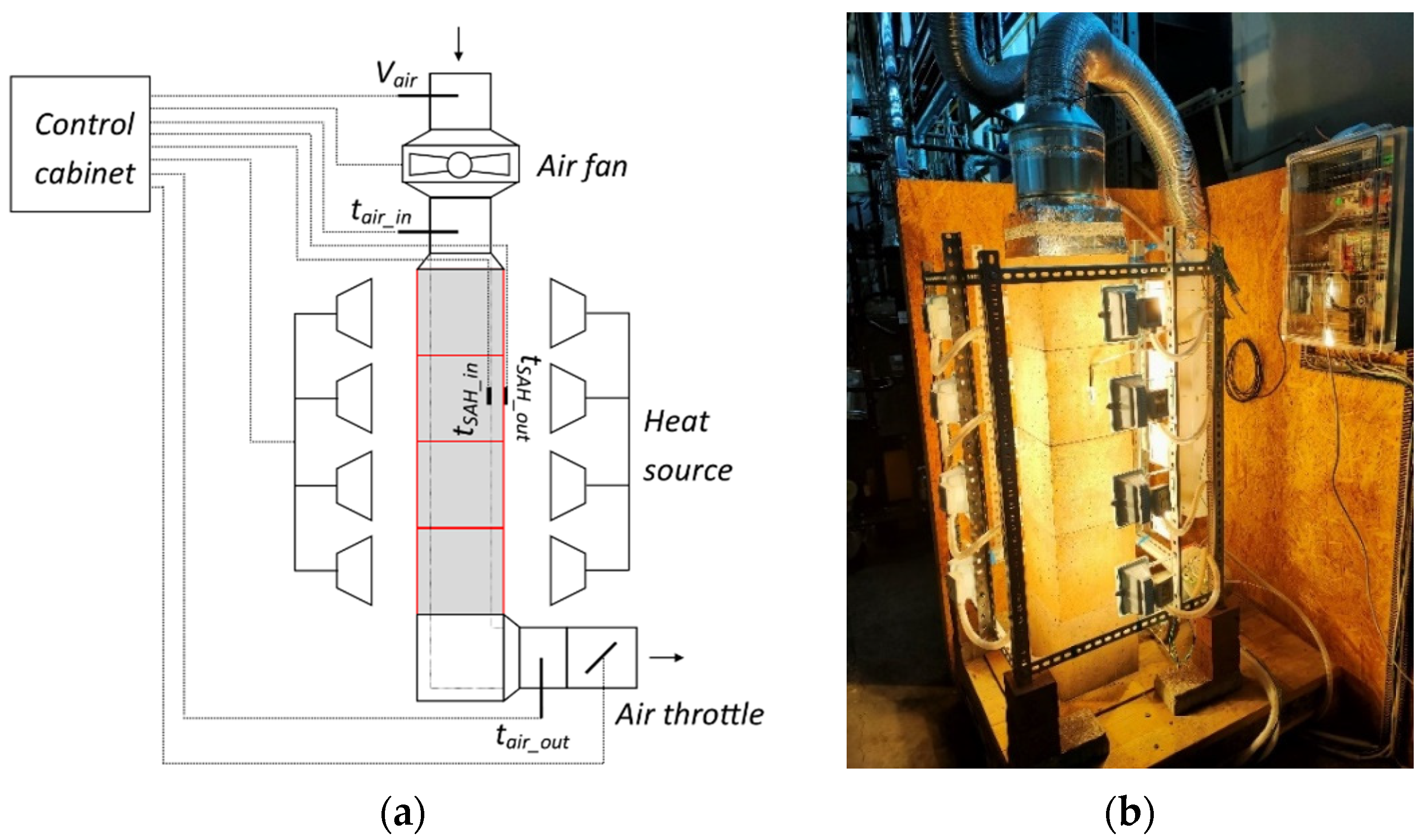
2.1. Experimental Rig and Procedure

The experimental rig was developed at the Faculty of Energy and Fuels, AGH UST in Krakow. It is equipped with a solar air heater, artificial light source, air fan, and control and measurement devices. The main parameters of the used elements are as follows:
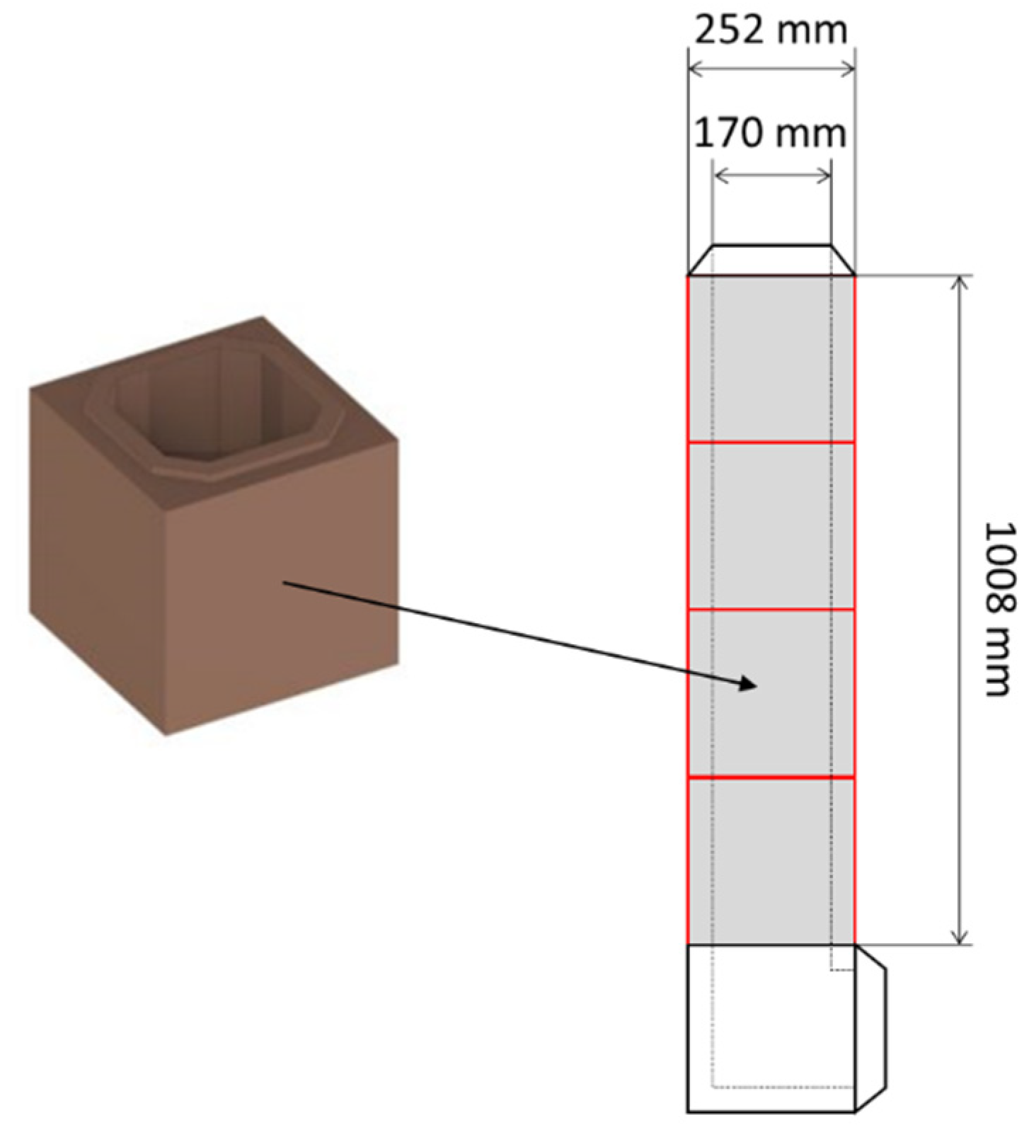
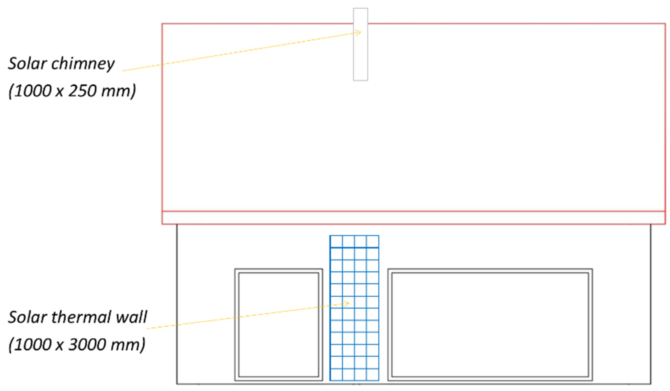
  • Solar air heater made of a special type of concrete (“akubet”) composed of ceramic aggregate with iron and manganese oxides on the aluminum cement bond. Good thermal parameters of “akubet” result from the fact that it was originally developed to use in wood-fired stoves [41,42]. The main geometrical and material parameters of the developed SAH are shown in Figure 2 and Table 3, respectively. A unit with a length of 1008 mm was tested, but in practical applications it can be extended by adding further cubic ceramic components.
  • An artificial heat source composed of 16 halogen lamps with individual electric power of 150 W (2400 W in total);
  • An air fan with a nominal flow of 840 m3/h;
  • A set of K-type (NiCR-Ni) thermocouple sensors to measure air temperature at the inlet and the outlet from the SAH (with a measuring range from −40 °C to 1200 °C and accuracy ±2.5 °C or ±0.0075 × [t]);
  • A set of resistance temperature sensors to measure the temperature of the internal and external walls of the SAH (with a measuring range from −50 °C to 400 °C and tolerance ±0.3 + 0.005 × [t]);
  • Thermoanemometer to measure airflow (with measuring range 0–20 m/s and tolerance ±0.02 m/s + 3%);
  • WAGO PFC200 PLC controller with a set of input and output modules;
  • The PC with CoDeSys software;
  • The infrared camera NEC ThermoTracer H2640 with a thermal resolution of 640 × 480 pixels, measuring range from 0 to 120 °C, and accuracy ±2% (of reading) or ±2 °C.
The scheme and the general view of the experimental rig during the experiment are shown in Figure 3.
The experimental procedure was divided into several steps. Based on the conducted measurements, the following aspects have been analyzed:
  • The relationship between the form of the SAH and the increase in the temperature of the ventilation air (point Section 3.1);
  • The relationship between the temperature of the internal walls of the solar air heater and the increase in the temperature of the ventilation air (point Section 3.2);
  • The relationship between the form of the SAH and the power transferred from the SAH to the ventilation air (point Section 3.3);
  • The relationship between the flow of the ventilation air and power transferred from the SAH to the ventilation air (point Section 3.4).
To investigate the impact of the form of the SAH on the increase in the temperature of the ventilation air and the power transferred from the SAH to the ventilation air, the following configurations of the experimental rig were introduced:
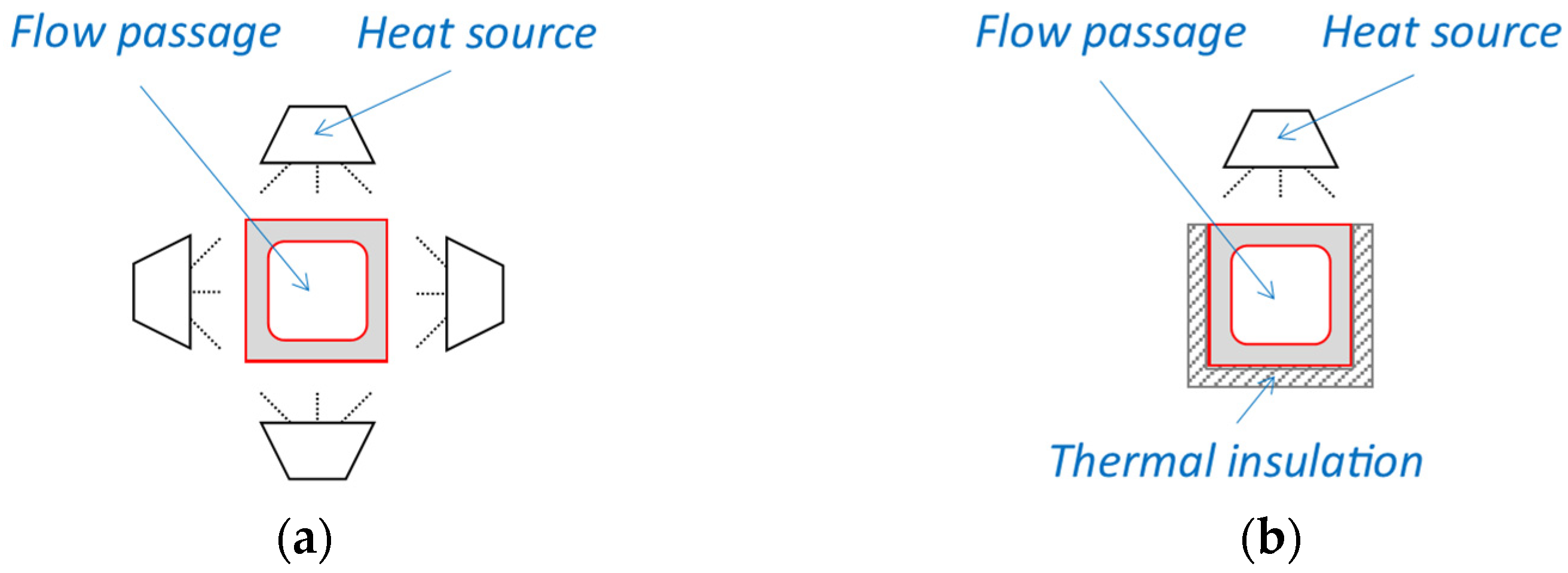
  • SAH in the form of the solar chimney was heated by an artificial heat source from all sides (see Figure 4a);
  • SAH in the form of a solar thermal wall was heated by an artificial heat source only from one side and other walls were insulated from the heat source (see Figure 4b). Opposite to the classic Trombe walls, glazing was not applied at the current stage, but it can be implemented in the future.

2.2. Numerical Analysis

The results obtained during the experiments have been used to perform numerical analysis. The numerical analysis includes calculations of the temperature efficiency of the proposed SAH and its impact on the energy performance of the exemplary residential building (point Section 3.5). All calculations have been performed according to the Polish methodology of evaluation of the energy performance of buildings [43], and using the following standards: EN 12831:2003—Heating systems in buildings–Method for calculation of the design heat load, ISO 13790:2008—Energy performance of buildings—Calculation of energy use for space heating and cooling, ISO 14683:2007—Thermal bridges in building construction—Linear thermal transmittance—Simplified methods and default values, and ISO 6946:2017—Building components and building elements—Thermal resistance and thermal transmittance—Calculation methods (the listed standards have been used in the versions that are valid in Poland).
The efficiency of the proposed solar air heater (ηSAH) can be calculated using the following formula [44]:
η S A H = θ s u p θ e x t θ i n t θ e x t ,     -
where θsup is a supply air temperature after the SAH (°C), θext is an external air temperature (°C), and θint is an internal air temperature (°C).
When considering both the solar air heater and heat recovery unit (recuperator), the total efficiency of the supply air preheating system can be calculated as follows [43]:
η o c , n = 1 [ ( 1 η H R S ) · ( 1 η S A H ) ] ,     -
where ηHRS is the efficiency of the heat recovery system and ηSAH is the efficiency of the solar air heater (-).
The total efficiency of the supply air preheating system is important from the standpoint of calculating the ventilation heat loss coefficient [43]:
H v e = ρ a · c a · k b v e , k · V v e , k , n ,   W / K
where qa is the air density (kg/m3), ca is the specific heat of the air (J/(kgK)), bve,k is the temperature correction factor for the outdoor airflow efficiency of the heat recovery system, and Vve,k,n is the time-averaged outdoor air stream in the heated zone (m3/s).
In the case of mechanical ventilation with a heat recovery system (recuperator and solar air heater), Equation (5) could be written as follows [43]:
H v e = 1200 · { [ β · ( 1 η o c , n ) · V s u ] + [ β · V x , s u ] + [ ( 1 β ) · V i n f ] } ,   W / K
where β is the share of the operation time of mechanical ventilation fans in a month equal to the use of the building in a month, ηoc,n is the total efficiency of the supply air preheating system, Vsu is the average primary airflow from the outside air in the heated zone (m3/s), Vx,su is an average additional infiltration air stream through leaks in the case of fan operation in mechanical supply and exhaust ventilation (m3/s), and Vinf is the average additional stream of external air infiltrating through leaks caused by the action of wind and thermal buoyancy (m3/s).
Based on the calculated value of the ventilation heat loss coefficient, monthly ventilation heat losses can be specified. Only nine months are included in the calculations (from September to May) [43].
Q v e , n = H v e · ( θ i n t , H θ e , n ) · t M · 10 3 ,   kWh / month
where Hve is the ventilation heat loss coefficient (W/K), θint,H is an average internal temperature (°C), θe,n is the monthly average external temperature (°C), and tm is the number of hours in the analyzed month (h).
Total monthly heat losses are the sum of the monthly transmission heat losses and the monthly ventilation heat losses. Transmission heat losses include heat lost through the external walls (or internal walls separating the heated zones from the unheated zones), roof, ground floor, windows, and doors [43].
Q H , h t , n = Q t r , n + Q v e , n ,   kWh / month
where Qtr is the monthly transmission heat losses (kWh/month) and Qve is the monthly ventilation heat losses (kWh/month).
The annual energy demand of a building for heating and ventilation can be calculated by summarizing both the monthly heat losses and monthly energy gains (heat gains from insolation and living heat gains) [43].
Q H , n d =   Q H , n d , n =   ( Q H , t , n η H , g n , n · Q H , g n , n ) ,   kWh a
where QH,ht,n is the total of monthly heat losses (kWh/month), ηH,gn,n is a coefficient of use for the heat gains in the given month, and QH,gn,n is the monthly energy gains (kWh/month).
The final and primary energy demand of a building for heating and ventilation can be calculated as follows [43]:
Q K , H = Q H , n d η H , t o t ,   kWh a
Q P , H =   ( Q K , H , i · w H , i + E e l , i · w e l , i ) ,   kWh a
where QH,nd is the annual energy demand of the building for heating and ventilation (kWh/a), ηH,tot is an average seasonal efficiency of the heating system (-), wH,i is the non-renewable prime energy factor for heat generation (-), Eel,i is the annual auxiliary electricity demand (kWh/a), and wel,i is the non-renewable prime energy factor for electricity generation.
Based on the calculated values of final and primary energy for heating and ventilation (and also considering energy demand for hot water production), it is possible to assess the energy, economic, and environmental aspects that result from the implementation of the solar air heater for the exemplary residential building. The main parameters of the analyzed building have been assumed as follows:
  • Building located in Krakow, Poland;
  • Building designed in passive technology;
  • The heat pump is used as a heat source (in central heating system and for heating domestic hot water);
  • Mechanical ventilation with recuperator is used as a ventilation system (assumed recuperator’s efficiency: 70%);
  • Air-handling unit with recuperator located in the attic (all air ducts insulated);
  • Supply air inlet connected with the outlet from the solar air heater;
  • Heated surface: 158.9 m2;
  • Ventilated volume: 362.8 m3;
  • Required airflow: 246.5 m3/h.
The general visualization of the analyzed residential building (designed and calculated in the ArCADia BIM software) is shown in Figure 5.

3. Results and Discussion

The increase in the temperature of the ventilation air in the solar air heater depends on several factors, including air flow rate, available heating area, and temperature of the internal wall of the SAH (which can result from the amount of stored solar energy). All of the aforementioned factors have been analyzed and discussed in the following sections. Furthermore, the obtained results have been used to perform numerical analysis.

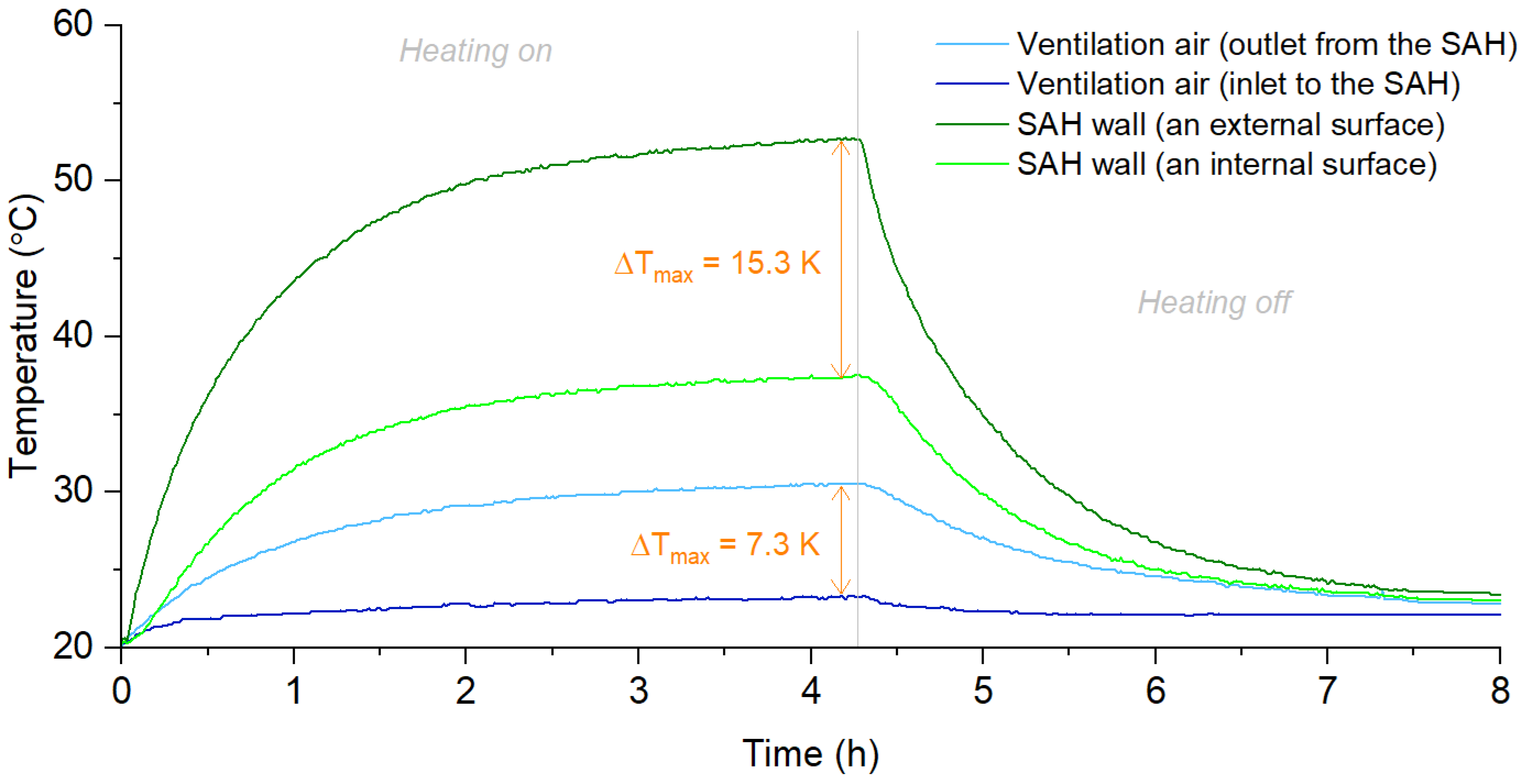
3.1. Relationship between the Form of the SAH and the Increase in the Temperature of the Ventilation Air

Among other parameters affecting the efficiency of heating ventilation air in the SAH, the crucial aspect is the available heating area. Therefore, the increase in ventilation air temperature was measured and compared for two assumed cases: the SAH in the form of a solar chimney, when all walls were heated by an artificial light source (Series 1a), and the SAH in the form of a thermal storage wall, when only one wall was heated by an artificial light source (Series 1b). Consequently, the heated surface in Series 1a was 0.25 m2, while in Series 2 it was 1.0 m2. In both discussed Series, airflow was set to approx. 150 m3/h, and the average light illumination was approx. 250–300 W/m2 (which corresponds to winter conditions). As is shown in Figure 6, the maximum increase in ventilation air temperature (approx. 7.3 K) was observed in Series 1a after 4 h of the experiment. Similarly, the increase in the ventilation air temperature in Series 1b was approx. 3.3 K (it was lower by 54.8% compared to Series 1a). By comparing these values, it can be noted that the solar air heater in the form of the thermal storage wall should be only approx. 2.2 times longer than the solar air heater in the form of the solar chimney to obtain the same increase in the ventilation air. In addition to Figure 6, which shows the increase in the temperature of the ventilation air when the SAH operates as either the solar chimney or the solar thermal wall, Table 4 summarizes the most important facts regarding the temperature measured.
By analyzing the obtained data, it can be concluded that the nominal operating parameters of the proposed SAH can be achieved for those days when the Sun’s operation time is longer than 4 h. Taking into account Polish conditions, this can occur on any sunny day of the year. When the Sun’s operation time is longer than 4 h, a solar air heater can both heat ventilation air and collect heat, which can then be dissipated after sunset. However, the final temperature of supply air (i.e., temperature at the outlet from the SAH) also depends on the solar irradiation, airflow, and initial temperature at the inlet to the unit. Furthermore, parameters such as wind speed, air humidity, cloud cover, etc., should be taken into account in real conditions.

3.2. Relationship between the Temperature of the Internal Walls of the SAH and the Increase in the Temperature of the Ventilation Air

The next aspect, which is important from the standpoint of the efficiency of heating ventilation air, is the temperature of the internal walls of the SAH. To assess the relationship between the temperature of the internal walls of the SAH and the increase in temperature of the ventilation air, the case of the SAH in the form of a solar chimney was analyzed. Similar to point Section 3.1, airflow was set to approx. 150 m3/h and the average light illumination was approx. 250–300 W/m2. As can be observed in Figure 7, the phase when the solar air heater’s internal surface temperature and the ventilation air temperature noticeably increased lasts approx. 4 h. After this time, these temperatures remain almost constant, and it should be noted that the light illumination, inlet air temperature, and airflow were constant during the experiment. The maximum difference in the outlet and inlet ventilation air temperature under stable working conditions was measured at a level of 7.3 K. When the lights are turned off, the temperatures start to drop. Nevertheless, the heat given off by the SAH allows the ventilation air to be heated for another 4 h. The average increase in the air temperature during the whole experiment was 4.4 K, and, in the first phase, 5.5 K when the light was on and 3.2 K when the light was off. In practice, these values can be significantly higher due to the higher length of the accumulation heat exchanger (and possible modifications in its geometry) and longer working time. Figure 7 shows variations in the ventilation air temperature and the temperature of the SAH surface, while Table 5 summarizes the maximum and average levels of the increases in the measured temperature.
By analogy with the previous discussion, the maximum and average temperature in real conditions will also be different from the values observed in the laboratory. Apart from the weather conditions, the real difference between the temperature of the internal and external walls of the SAH can be derived from the structure and geometry of the ceramic modules (including greater wall thickness at the corners).

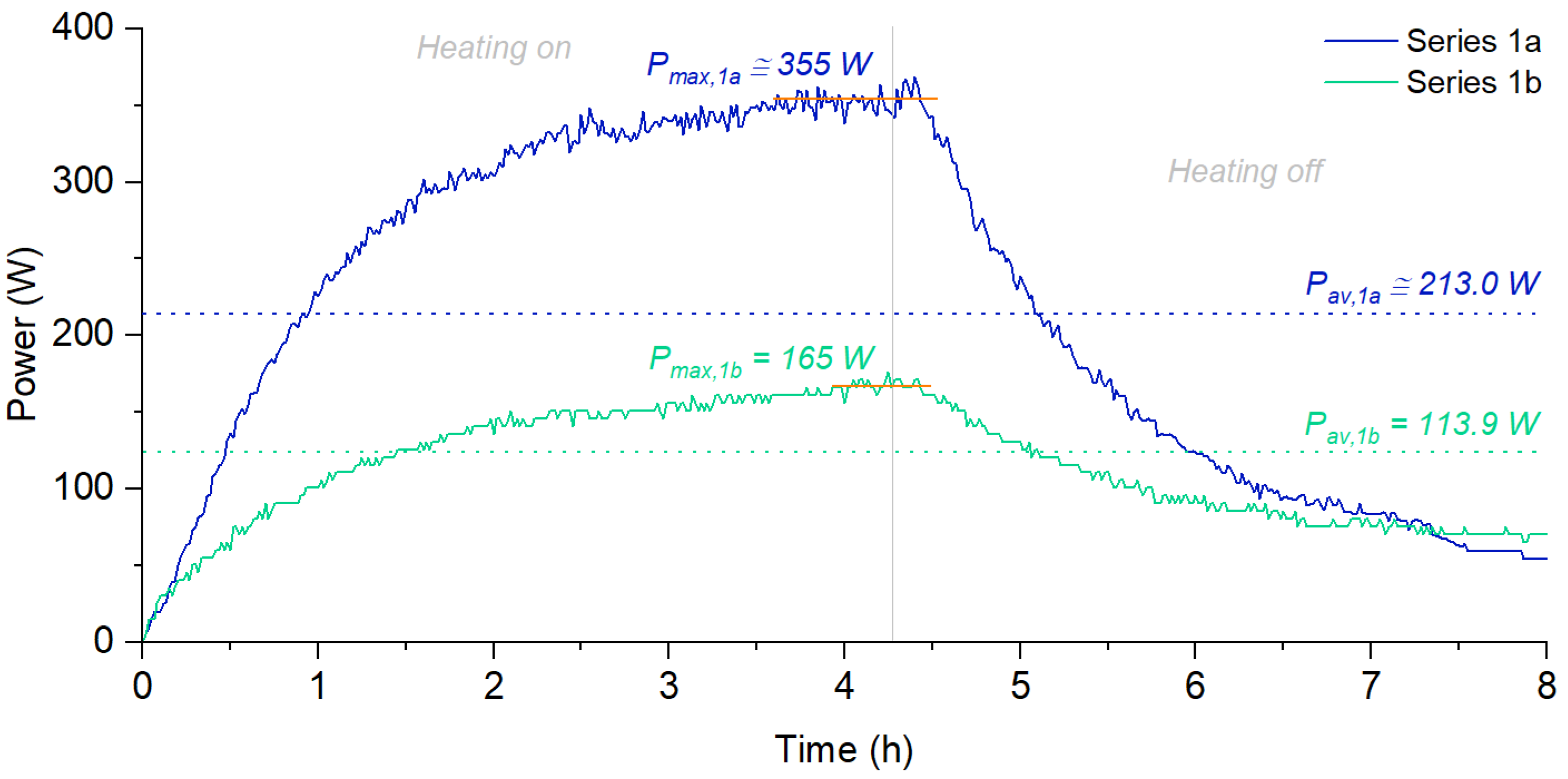
3.3. Relationship between the Form of the SAH and the Power Transferred from the SAH to the Ventilation Air

The power transferred from the SAH to the ventilation air is a direct result of the difference between the temperatures of ventilation air at the inlet and outlet from the SAH, the temperature of the internal surface of the SAH, and airflow (which, as previously mentioned, was set to 150 m3/h). The average value of power observed under stable working conditions was approx. 355.0 W when the SAH operated as a solar chimney (Series 2a), and approx. 165.0 W when the SAH operated as a solar thermal wall (Series 2b). Taking into account the whole experiment, the average value of power transferred from the SAH to the ventilation air was 213.0 W in Series 1a, and 113.9 W in Series 1b; consequently, the heat transferred from the SAH to the ventilation air during the whole process was approx. 1715.6 Wh and 910.3 Wh, respectively. Variations in the power transferred from the SAH to the ventilation air are shown in Figure 8, and the summarized values of power and heat transfer from the SAH to the ventilation air are given in Table 6.
Considering the fact that nominal operating parameters of the tested SAH can be achieved after 4 h, the amount of heat transferred to the ventilation air during sunny days can be significantly higher. According to [45], the length of the light day in Krakow (Poland) varies from approx. 8 h during the winter to approx. 16 h during the summer; in practice, the exact time of sun operation is a result of the weather conditions, cloud cover, and other factors, so the real time of the SAH operation is shorter than the theoretical length of the light day. Conversely, taking into account sunny days in March, the time of sun operation can exceed 11 h. Even ignoring the fact that solar irradiation is higher than the actual heating capacity of the experimental rig, the theoretically available daily heat generation in the developed SAH can be higher than 4000 Wh with SAH in the form of a 1m long solar chimney, and higher than 2000 Wh with SAH in the form of 1m long solar thermal wall.

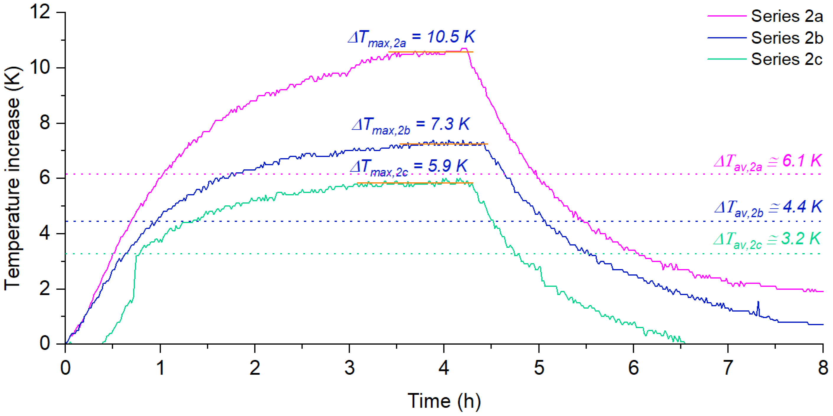
3.4. Relationship between the Flow and the Increase in the Temperature of the Ventilation Air

The volume of airflow results from the building’s demand for the supply of air. Moreover, it is not usually constant over time. Therefore, it is important to determine the level of temperature, which can be achieved at the outlet from the SAH depending on the actual airflow. This part of the experiment has been performed for the SAH in the form of a solar chimney. As is shown in Figure 9, the highest increase in the temperature of the ventilation air at the outlet from the SAH, 10.5 K, was observed when airflow was set to 100 m3/h (Series 2a). This value was higher by 43.8% compared to the 7.3 K observed during Series 2b when the airflow was set to 150 m3/h, and 78.0% compared to 5.9 K measured during Series 2c when the airflow was set to 200 m3/h. Each time, the average temperature of inlet air was approx. 22 °C. Considering the average increase in the temperature of the ventilation air during the whole analyzed process, the difference was even higher. The average difference between the ventilation air at the outlet versus the inlet to the SAH was 6.1 K in Series 2a, which was higher by 38.6% in comparison to Series 2b (4.4 K), and by 90.6% in comparison to Series 2c (3.2 K). Consequently, it may be stated that the value of the temperature increase in the SAH is inversely proportional to the ventilation airflow. Figure 9 shows variations in the ventilation air temperature at the outlet from the SAH, while Table 7 summarizes the maximum and average levels of the increases in the measured temperature.

3.5. Relationship between the Flow of the Ventilation Air and Power Transferred from the SAH to the Ventilation Air

By comparing the results obtained in Series 2a–2c, it can be concluded that the highest level of power transferred from the accumulation heat exchanger to the ventilation air was achieved when airflow was 200 m3/h. The average value of power observed under stable working conditions was then approx. 385 W, compared to approx. 355.0 W measured in Series 2b and approx. 348 W measured in Series 2a. Consequently, the heat transfers from the SAH to the ventilation air were approx. 1848.7 Wh, 1715.6 Wh, and 1607.8 Wh, respectively. Variations in the power transferred from the SAH to the ventilation air during the analyzed series are shown in Figure 10, and the summarized values of power and heat transfer from the SAH to the ventilation air are given in Table 8.
By analyzing the obtained data, it can be concluded that the higher the airflow, the more heat can be transferred from the SAH to the ventilation air. During the discussed experiments, approx. 15% more heat was transferred to the air in Series 2c (when its flow was set to 200 m3/h) compared to Series 2a (when airflow was set to 100 m3/h). In real buildings, the amount of ventilation air is higher compared to the value set during the conducted experiments. Consequently, the amount of heat transferred from the SAH to the ventilation air can be higher than estimated in laboratory conditions.

3.6. Estimation of the Efficiency of the Proposed SAH and its Impact on the Building Performance

Results of the carried-out studies were used to estimate the temperature efficiency of preheating the ventilation air in the SAH. Calculations were made according to Equation (3) using data collected during experimental studies. The currently available experimental data only allowed for the preliminary estimation of the efficiency of the proposed SAH and will be extended in further works. According to the Polish methodology of evaluation of the energy performance of buildings, only nine months have been included in the analysis. The assumed external temperature values are the average monthly values for Krakow (Poland). Two cases were analyzed:
  • Case A: the SAH operates as a solar chimney;
  • Case B: the SAH operates as a solar thermal wall (see Figure 11);
As can be observed in Table 9, the estimated efficiency of the SAH ranged from 0.14 to 0.47 in Case A and from 0.53 to 0.71 in Case B. From April to October, estimated efficiency exceeds 100%, which means that, in these months, the proposed SAH operates in the heating mode only for a limited time. The results of the calculations are shown in Table 8. By averaging the monthly efficiency values, the total efficiency of the SAH was calculated. In Case A, the total efficiency was estimated as 0.25, while in Case B it is 0.78. Such a high difference in the efficiency of the SAH is mainly a result of the difference in the heated area (1 m2 in case A, and 3 m2 in case B).
The estimated values of the seasonal efficiency of the analyzed SAH system (both in the form of a solar chimney and solar thermal wall) have been used to calculate the energy performance of the exemplary residential building. Thus, the final and primary energy consumption rates for heating and ventilation have been assessed (which also includes the energy demand for hot water production). As shown in Table 10, by installing the SAH in the form of a solar chimney (Case A), the reduction in the final energy usage can be at a level of 190.7 kWh/a (approx. 4.8% compared to a building without the SAH), while by installing the SAH in the form of a solar thermal wall (Case B), this value is 556.1 kWh/a (approx. 14.0%). Considering the actual price of electricity in EUR is 0.2369 per kWh (based on the average price in the EU for the second half of 2021 [46]), the theoretical seasonal savings in heating costs can be achieved at a level of 45.2 EUR (Case A) and 131.7 EUR (Case B), respectively. In practice, these values could be significantly lower because the additional power would be consumed by the air-handling unit due to higher airflow resistance in the SAH area. Furthermore, taking into account investment costs and operational benefits, the Simple Payback Time (SPBT) and Net Present Value (NPV) can be calculated according to the equations given in [47]. In this case, the SPBT was estimated at approx. 4.9 years, while in Case B, it was estimated at approx. 20.0 years. Respectively, the NPV values were calculated at approx. 166.9 EUR and −1 512.7 EUR (assuming a period of 15 years and a discount rate of 8%). Although the calculated payback time is long (especially when the solar air heater in the form of the thermal wall is discussed), the implementation of SAH should also be considered from the standpoint of energy security (including the ability to ensure the energy independence of the building) and requirements given by energy certification rules. Furthermore, the limited resources of primary energy and the constantly rising prices should be taken into account. Conversely, as was discussed previously, the real performance of the proposed SAH can be higher than the calculated values, and thus the payback time can be shorter in practice.

4. Conclusions

This paper investigates the possibility of developing a solar air heater in the form of a solar chimney and solar thermal wall. The novel concept of a unit composed of an accumulation ceramic material was proposed and discussed. Experiments have been carried out under laboratory conditions using a specially developed prototype. The main conclusions are as follows:
  • As was shown, by using solar radiation (simulated by an artificial light source), it is possible to heat the ceramic material and use the accumulated heat to preheat the ventilation air for the subsequent hours.
  • The power transferred from the solar air heater to the ventilation air was mainly a result of the difference between the temperature of the ventilation air at the inlet and outlet from the unit, the temperature of the internal surface of the unit, and airflow. When airflow was set to 150 m3/h, the maximum power observed under stable working conditions was approx. 355.0 W (when the developed solar air heater operated as a solar chimney), and approx. 165.0 W (when it operated as a solar thermal wall).
  • A higher power, approx. 385 W, was observed when the developed solar air heater operated as a solar chimney and the airflow was 200 m3/h.
  • Experimental results have been used to calculate the efficiency of the solar air heater in real conditions and assess the impact of the solar air heater on the energy performance of the exemplary residential building. The total efficiency in the case of the solar chimney was estimated as 0.25, while in the case of the thermal wall it was estimated as 0.78, which resulted in the annual reduction in the final energy usage at a level of 190.7 kWh and 556.1 kWh, respectively (4.8 and 14.0%).
  • In practice, the total efficiency of the proposed solutions can be significantly higher due to the possibility of increasing the length and shape of the solar air heater.

Author Contributions

Conceptualization, K.S. and K.P.-F.; methodology, K.S. and K.P.-F.; software, K.S.; formal analysis, K.S.; investigation, K.S. and K.P.-F.; resources, K.S. and K.P.-F.; data curation, K.S.; writing—original draft preparation, K.S., and K.P.-F.; visualization, K.S.; project administration, K.S.; funding acquisition, K.S. and K.P.-F. All authors have read and agreed to the published version of the manuscript.

Funding

This work was carried out under Subvention no. 16.16.210.476 from the Faculty of Energy and Fuels, AGH University of Science and Technology in Krakow.

Acknowledgments

The substantive and financial support of the Cebud company and the Institute of Sustainable Energy in Krakow was obtained.

Conflicts of Interest

The authors declare no conflict of interest.

References

  1. Santamouris, M.; Vasilakopoulou, K. Present and future energy consumption of buildings: Challenges and opportunities towards decarbonisation. E-Prime-Adv. Electr. Eng. Electron. Energy 2021, 1, 100002. [Google Scholar] [CrossRef]
  2. Krawczyk, D.A. Analysis of Energy Consumption for Heating in a Residential House in Poland. Energy Procedia 2016, 95, 216–222. [Google Scholar] [CrossRef]
  3. Shayan, M.E. Solar Energy and Its Purpose in Net-Zero Energy Building. In Zero-Energy Buildings—New Approaches and Technologies; IntechOpen: London, UK, 2020. [Google Scholar] [CrossRef]
  4. Żołądek, M.; Filipowicz, M.; Sornek, K.; Figaj, R. Energy performance of the photovoltaic system in urban area-case study. IOP Conf. Ser. Earth Environ. Sci. 2019, 214, 012123. [Google Scholar] [CrossRef]
  5. Papis-Frączek, K.; Sornek, K. A Review on Heat Extraction Devices for CPVT Systems with Active Liquid Cooling. Energies 2022, 15, 6123. [Google Scholar] [CrossRef]
  6. Goel, V.; Hans, V.S.; Singh, S.; Kumar, R.; Pathak, S.K.; Singla, M.; Bhattacharyya, S.; Almatrafif, E.; Gill, R.S.; Saini, R.P. A comprehensive study on the progressive development and applications of solar air heaters. Solar Energy 2021, 229, 112–147. [Google Scholar] [CrossRef]
  7. Pachori, H.; Choudhary, T.; Sheorey, T. Significance of thermal energy storage material in solar air heaters. Mater. Today Proc. 2022, 56, 126–134. [Google Scholar] [CrossRef]
  8. Sharma, A.; Tyagi, V.V.; Chen, C.R.; Buddhi, D. Review on thermal energy storage with phase change materials and applications. Renew. Sustain. Energy Rev. 2009, 13, 318–345. [Google Scholar] [CrossRef]
  9. Labus, M.; Labus, K. Thermal conductivity and diffusivity of fine-grained sedimentary rocks. J. Therm. Anal. Calorim. 2018, 132, 1669–1676. [Google Scholar] [CrossRef]
  10. Kubiś, M.; Pietrak, K.; Cieślikiewicz, Ł.; Furmański, P.; Wasik, M.; Seredyński, M.; Wiśniewski, T.S.; Łapka, P. On the anisotropy of thermal conductivity in ceramic bricks. J. Build. Eng. 2020, 31, 101418. [Google Scholar] [CrossRef]
  11. Asadi, I.; Shafigh, P.; bin Abu Hassan, Z.F.; Mahyuddin, N.B. Thermal conductivity of concrete—A review. J. Build. Eng. 2018, 20, 81–93. [Google Scholar] [CrossRef]
  12. Hillel, D. Thermal properties and processes. Encycl. Soils Environ. 2005, 4, 156–163. [Google Scholar] [CrossRef]
  13. Soltani, F.; Toghraie, D.; Karimipour, A. Experimental measurements of thermal conductivity of engine oil-based hybrid and mono nanofluids with tungsten oxide (WO3) and MWCNTs inclusions. Powder Technol. 2020, 371, 37–44. [Google Scholar] [CrossRef]
  14. Abdin, Z.; Khalilpour, K.R. Single and Polystorage Technologies for Renewable-Based Hybrid Energy Systems. In Polygeneration with Polystorage: For Chemical and Energy Hubs; Academic Press: Cambridge, MA, USA, 2019; pp. 77–131. [Google Scholar] [CrossRef]
  15. Szokolay, S. Passive heating and cooling. In Sun Power (Second Edition): An Introduction to the Applications of Solar Energy; Pergamon Press: Oxford, UK, 1983; Volume 3, pp. 113–131. [Google Scholar] [CrossRef]
  16. Passive Solar Design—Sustainability. Available online: https://sustainability.williams.edu/green-building-basics/passive-solar-design/ (accessed on 14 August 2022).
  17. Xiong, Q.; Alshehri, H.M.; Monfaredi, R.; Tayebi, T.; Majdoub, F.; Hajjar, A.; Delpisheh, M.; Izadi, M. Application of phase change material in improving trombe wall efficiency: An up-to-date and comprehensive overview. Energy Build. 2022, 258, 111824. [Google Scholar] [CrossRef]
  18. Quesada, G.; Rousse, D.; Dutil, Y.; Badache, M.; Hallé, S. A comprehensive review of solar facades. Opaque solar facades. Renew. Sustain. Energy Rev. 2012, 16, 2820–2832. [Google Scholar] [CrossRef]
  19. Hu, Z.; He, W.; Ji, J.; Zhang, S. A review on the application of Trombe wall system in buildings. Renew. Sustain. Energy Rev. 2017, 70, 976–987. [Google Scholar] [CrossRef]
  20. Hami, K.; Draoui, B.; Hami, O. The thermal performances of a solar wall. Energy 2012, 39, 11–16. [Google Scholar] [CrossRef]
  21. Hu, Z.; Zhang, S.; Hou, J.; He, W.; Liu, X.; Yu, C.; Zhu, J. An experimental and numerical analysis of a novel water blind-Trombe wall system. Energy Convers. Manag. 2020, 205, 112380. [Google Scholar] [CrossRef]
  22. Dabaieh, M.; Serageldin, A.A. Earth air heat exchanger, Trombe wall and green wall for passive heating and cooling in premium passive refugee house in Sweden. Energy Convers. Manag. 2020, 209, 112555. [Google Scholar] [CrossRef]
  23. Singh, A.P.; Akshayveer; Kumar, A.; Akshayveer; Kumar, A.; Singh, O.P. Designs for high flow natural convection solar air heaters. Solar Energy 2019, 193, 724–737. [Google Scholar] [CrossRef]
  24. Singh, A.P.; Kumar, A.; Akshayveer; Singh, O.P. Effect of integrating high flow naturally driven dual solar air heaters with Trombe wall. Energy Convers. Manag. 2021, 249, 114861. [Google Scholar] [CrossRef]
  25. Bevilacqua, P.; Bruno, R.; Szyszka, J.; Cirone, D.; Rollo, A. Summer and winter performance of an innovative concept of Trombe wall for residential buildings. Energy 2022, 258, 124798. [Google Scholar] [CrossRef]
  26. Mokni, A.; Lashin, A.; Ammar, M.; Mhiri, H. Thermal analysis of a Trombe wall in various climatic conditions: An experimental study. Solar Energy 2022, 243, 247–263. [Google Scholar] [CrossRef]
  27. Rabani, M. Experimental comparison of energy and exergy analysis of a new designed and a Normal Trombe wall. Energy 2022, 260, 125050. [Google Scholar] [CrossRef]
  28. Li, W.; Chen, W. Numerical analysis on the thermal performance of a novel PCM-encapsulated porous heat storage Trombe-wall system. Solar Energy 2019, 188, 706–719. [Google Scholar] [CrossRef]
  29. Duan, S.; Wang, L.; Zhao, Z.; Zhang, C. Experimental study on thermal performance of an integrated PCM Trombe wall. Renew. Energy 2021, 163, 1932–1941. [Google Scholar] [CrossRef]
  30. Li, J.; Zhang, Y.; Zhu, Z.; Zhu, J.; Luo, J.; Peng, F.; Sun, X. Thermal comfort in a building with Trombe wall integrated with phase change materials in hot summer and cold winter region without air conditioning. Energy Built Environ. 2022, in press. [Google Scholar] [CrossRef]
  31. Wijesuriya, S.; Tabares-Velasco, P.C.; Biswas, K.; Heim, D. Empirical validation and comparison of PCM modeling algorithms commonly used in building energy and hygrothermal software. Build. Environ. 2020, 173, 106750. [Google Scholar] [CrossRef]
  32. Javidan, M.; Asgari, M.; Gholinia, M.; Nozari, M.; Asgari, A.; Ganji, D.D. Thermal energy storage inside the chamber with a brick wall using the phase change process of paraffinic materials: A numerical simulation. Theor. Appl. Mech. Lett. 2022, 12, 100329. [Google Scholar] [CrossRef]
  33. Javidan, M.; Asgari, M.; Gholinia, M.; Nozari, M.; Asgari, A.; Ganji, D.D. Investigation of convection and radiation heat transfer of paraffinic materials and storage of thermal energy in melting process of PCMs in the cavity with transparent inner walls. Energy Rep. 2022, 8, 5522–5532. [Google Scholar] [CrossRef]
  34. Yang, L.; Dhahad, H.A.; Chen, M.; Huang, Z.; Anqi, A.E.; Rajhi, A.A.; Qader, D.N. Transient analysis of buildings with Trombe wall in a southern envelope and strengthening efficacy by adding phase change material. J. Build. Eng. 2022, 55, 104670. [Google Scholar] [CrossRef]
  35. Sornek, K.; Filipowicz, M.; Rzepka, K. The development of a thermoelectric power generator dedicated to stove-fireplaces with heat accumulation systems. Energy Convers. Manag. 2016, 125, 185–193. [Google Scholar] [CrossRef]
  36. Abdeen, A.; Serageldin, A.A.; Ibrahim, M.G.E.; El-Zafarany, A.; Ookawara, S.; Murata, R. Experimental, analytical, and numerical investigation into the feasibility of integrating a passive Trombe wall into a single room. Appl. Therm. Eng. 2019, 154, 751–768. [Google Scholar] [CrossRef]
  37. Stazi, F.; Mastrucci, A.; Munafò, P. Life cycle assessment approach for the optimization of sustainable building envelopes: An application on solar wall systems. Build. Environ. 2012, 58, 278–288. [Google Scholar] [CrossRef]
  38. Özdenefe, M.; Atikol, U.; Rezaei, M. Trombe wall size-determination based on economic and thermal comfort viability. Solar Energy 2018, 174, 359–372. [Google Scholar] [CrossRef]
  39. Rabani, M.; Kalantar, V.; Rabani, M. Heat transfer analysis of a Trombe wall with a projecting channel design. Energy 2017, 134, 943–950. [Google Scholar] [CrossRef]
  40. Lin, Y.; Ji, J.; Lu, X.; Luo, K.; Zhou, F.; Ma, Y. Thermal and electrical behavior of built-middle photovoltaic integrated Trombe wall: Experimental and numerical study. Energy 2019, 189, 116173. [Google Scholar] [CrossRef]
  41. Sornek, K.; Filipowicz, M.; Rzepka, K. Study of clean combustion of wood in a stove-fireplace with accumulation. J. Energy Inst. 2017, 90, 613–623. [Google Scholar] [CrossRef]
  42. Sornek, K. A study of selected aspects of the operation of thermoelectric generator incorporated in a biomass-fired stove. E3S Web Conf. 2016, 10, 00087. [Google Scholar] [CrossRef]
  43. Polish Methodology of Evaluation of the Energy Performance of Buildings. Available online: https://sip.lex.pl/akty-prawne/dzu-dziennik-ustaw/metodologia-wyznaczania-charakterystyki-energetycznej-budynku-lub-18176491 (accessed on 17 August 2022).
  44. Pecceu, S.; Caillou, S. Efficiency of heat recovery ventilation in real conditions: Feedback from several measurement campaigns|AIVC. In Proceedings of the 40th AIVC—8th TightVent—6th Venticool Conference, Ghent, Belgium, 15–16 October 2019. [Google Scholar]
  45. Solar Calendar for Krakow. Available online: https://pl.365.wiki/world/poland/krakow/sun/calendar/ (accessed on 1 September 2022).
  46. Electricity Price Statistics—Statistics Explained. Available online: https://ec.europa.eu/eurostat/statistics-explained/index.php?title=Electricity_price_statistics (accessed on 19 August 2022).
  47. Sornek, K.; Goryl, W.; Figaj, R.; Dąbrowska, G.; Brezdeń, J. Development and Tests of the Water Cooling System Dedicated to Photovoltaic Panels. Energies 2022, 15, 5884. [Google Scholar] [CrossRef]
Figure 1. Classifications of thermal energy storage systems [7].
Energies 15 06583 g001
Figure 2. The main geometrical parameters of the tested SAH.
Energies 15 06583 g002
Figure 3. The experimental rig: the scheme (a) and the general view (b).
Energies 15 06583 g003
Figure 4. The configurations of the experimental rig when (a) SAH operated as the solar chimney and (b) when SAH operated as a part of the solar thermal wall.
Energies 15 06583 g004
Figure 5. The general visualization of the analyzed building: (a) north façade, (b) south façade.
Energies 15 06583 g005
Figure 6. The increase in the temperature of the ventilation air when the SAH operated as a solar chimney (Series 1a) and a solar thermal wall (Series 1b).
Energies 15 06583 g006
Figure 7. Variations in the ventilation air temperature (at the outlet and inlet to the SAH) and temperature of the SAH surface when it operated as the solar chimney (Series 1a).
Energies 15 06583 g007
Figure 8. Variations in the power transferred from the SAH to the ventilation air when the SAH operated as a solar chimney (Series 1a) and a solar thermal wall (Series 1b).
Energies 15 06583 g008
Figure 9. The increase in the temperature of the ventilation air when the SAH operated as a solar chimney and airflow was set to 100 m3/h (Series 2a), 150 m3/h (Series 2b), and 200 m3/h (Series 2c).
Energies 15 06583 g009
Figure 10. Variations in the power transferred from the SAH to the ventilation air when the SAH operated as a solar chimney and airflow was set to 100 m3/h (Series 2a), 150 m3/h (Series 2b), and 200 m3/h (Series 2c).
Energies 15 06583 g010
Figure 11. The solar façade of the analyzed building including the SAH in the form of a solar chimney and solar thermal wall.
Energies 15 06583 g011
Table 1. The main parameters of selected solid–fluid materials for sensible heat storage [8,9,10,11,12,13].
MaterialTemperature Range
°C
Thermal
Conductivity
W/(m K)
Density
kg/m3
Specific Heat
J/kg K
Rock200.4–7.02560879
Brick200.6–1.01600840
Concrete200.6–3.31900–2300880
Water0–1000.5710004190
Engine oilUp to 1600.138881880
Table 2. The comparison between the proposed SAH and SHS systems available in the literature.
AuthorsThe Form of SAHParameters/ObjectiveHeat AccumulationConducted WorksRef.
Current workSolar chimney and solar thermal wallDevelopment of a novel configuration of SAH that is composed of inexpensive accumulative material and tests the operation parameters of the proposed SAH composed in the form of the solar chimney and solar thermal wall.YesNumerical and
experimental studies
-
Singh et al. (2021)Trombe wallInvestigation of a new concept of
integrating a high-flow naturally-driven dual heating system of Trombe wall integrated with SAH.
NoNumerical studies[24]
Bevilacqua et al. (2022)Trombe wallIntroduction of an innovative configuration of a modular Trombe wall that can be easily integrated into existing buildingsNoNumerical studies[25]
Mokni et al. (2022)Trombe wallEvaluation of the different heat exchange coefficients, the thermo-circulation in the gap, and the total amount of heat captured during the sunshine hours.NoNumerical and
experimental studies
[26]
Abdeed et al. (2019)Trombe wallOptimum design of Trombe wall,
enhancing the thermal comfort.
NoNumerical studies[36]
Stazi et al. (2012)Trombe wallThe optimization of energy and environmental performances of complex building envelopes.NoNumerical studies[37]
Özdenefe et al. (2018)Trombe wallDeveloping an approach for revealing the conditions and features of economically feasible Trombe walls by taking both annual energy consumption and thermal comfort into consideration.NoNumerical studies[38]
Rabani et al. (2017)Trombe wall with projecting
channel design
Assessment of the temperature variation of the Trombe wall back and absorber over a 24 h basis for winters and summers.NoNumerical studies[39]
Javidan et al. (2022)N/AStudy the melting process of PCM by applying constant heat flux and temperature.YesNumerical studies[32]
Duan et al. (2020)Trombe wall with PCMThermal performance improvement of Trombe wall via PCM encapsulated
as a thermal storage.
YesExperimental studies[29]
Yang et al. (2022)Trombe wall with PCMThe contrast of energy analysis of a typical building and a building equipped with a Trombe wall. YesNumerical and
experimental studies
[34]
Li and Chen (2019)Trombe wall with PCMAssessment and discussion of a new design of a solar composite wall with the porous heat storage layer. YesNumerical studies[28]
Lin et al. (2019)Trombe wall with photovoltaic
(PV) panel
Investigation of a PV panel integrated with Trombe wall for dual purposes (electricity generation and space heating) and comparison with the classic Trombe wall.NoNumerical and
experimental studies
[40]
Table 3. The main parameters of the “akubet” material used in the tested SAH.
Temperature Range
°C
Thermal Conductivity
W/(m K)
Density
kg/m3
Specific Heat
J/(kg K)
Up to 3501.812750640
Table 4. Summarization of the increase in the temperature of the ventilation air when the SAH operated as a solar chimney (Series 1a) and a solar thermal wall (Series 1b).
ParameterSeries 1aSeries 1b
The maximum increase in the temperature observed during the experiment, K7.33.3
The average increase in the temperature (during the whole process), K4.42.3
The average increase in the temperature in the first phase (when the light was on), K5.52.5
The average increase in the temperature in the second phase (when the light was off), K3.22.1
Table 5. Summarization of the temperature of the ventilation air and the SAH surface when it operated as a solar chimney (Series 1a).
ParameterVentilation AirSAH Surface
Inlet to the SAHAn outlet from the SAHInside
SAH
Outside
SAH
Maximum temperature observed during the experiment, °C22.030.237.552.8
The average temperature (during the whole process), °C26.430.338.6
The average temperature in the first phase (when the light was on), °C27.633.546.5
The average temperature in the second phase (when the light was off), °C25.227.130.5
Table 6. Power and the heat transferred from the SAH to the ventilation air when the SAH operated as a solar chimney (Series 1a) and a solar thermal wall (Series 1b).
ParameterSeries 1aSeries 1b
Maximum power observed during the experiment, W355.0165.0
The average power (during the whole process), W213.0113.9
The average power in the first phase (when the light was on), W270.2125.3
The average power in the second phase (when the light was off), W155.9101.3
The heat transferred from the accumulation heat exchanger to the ventilation air (during the whole process), Wh1715.6910.3
The heat transferred from the accumulation heat exchanger to the ventilation air in the first phase (when the light was on), Wh1107.8520.2
The heat transferred from the accumulation heat exchanger to the ventilation air in the second phase (when the light was off), Wh607.8390.1
Table 7. Summarization of the increase in the temperature of the ventilation air when the SAH operated as a solar chimney and airflow was set to 100 m3/h (Series 2a), 150 m3/h (Series 2b), and 200 m3/h (Series 2c).
ParameterSeries 2aSeries 2bSeries 2c
The maximum increase in the temperature observed during the experiment, K10.77.36.0
The average increase in the temperature (during the whole process), K6.14.43.2
The average increase in the temperature in the first phase (when the light was on), K7.75.54.3
The average increase in the temperature in the first phase (when the light was off), K4.23.21.8
Table 8. Summarization of the power transferred from the SAH to the ventilation air when the SAH operated as a solar chimney and airflow was set to 100 m3/h (Series 2a), 150 m3/h (Series 2b), and 200 m3/h (Series 2c).
ParameterSeries 2aSeries 2bSeries 2c
Maximum power observed during the experiment, W348.0355385.0
The average power (during the whole process), W200.9213.0228.8
The average power in the first phase (when the light was on), W252.1270.2292.5
The average power in the second phase (when the light was off), W149.9155.9164.9
The heat transferred from the accumulation heat exchanger to the ventilation air (during the whole process), Wh1607.81715.61848.7
The heat transferred from the accumulation heat exchanger to the ventilation air in the first phase (when the light was on), Wh1008.21107.81213.7
The heat transferred from the accumulation heat exchanger to the ventilation air in the second phase (when the light was off), Wh599.6607.8635.0
Table 9. The estimation of the average monthly efficiency of the SAH in the form of a solar chimney and thermal storage wall.
Parameter/MonthIIIIIIIVVIXXXIXII
The average monthly efficiency of solar chimney0.140.130.180.260.440.470.280.170.14
The average monthly efficiency of solar thermal wall0.560.530.71>1.00>1.00>1.00>1.000.660.58
Table 10. The comparison of the final and primary energy consumption in the exemplary residential building without the SAH and with the SAH in the form of a solar chimney (Case A) or solar thermal wall (Case B).
ParameterBuilding without the SAHBuilding with the SAH
Case ACase B
The final energy performance index, kWh/(m2a)25.023.821.5
Final energy consumption, kWh/a3972.53781.83416.4
The primary energy performance index, kWh/(m2a)74.971.564.5
Primary energy consumption, kWh/a11901.611361.410249.1
Reduction in the final energy consumption, kWh/a-190.7556.1
Reduction in the final energy consumption, %-4.814.0
Reduction in the number of days when the operation of the heat pump is required, h/a-5.016.3
Publisher’s Note: MDPI stays neutral with regard to jurisdictional claims in published maps and institutional affiliations.

