Article

Installation’s Conception in the Field of Renewable Energy Sources for the Needs of the Silesian Botanical Garden

by
Małgorzata Jastrzębska
Department of Geotechnics and Roads, Faculty of Civil Engineering, Silesian University of Technology, Akademicka 5, 44-100 Gliwice, Poland
Energies 2022, 15(18), 6598; https://doi.org/10.3390/en15186598
Submission received: 8 August 2022 / Revised: 5 September 2022 / Accepted: 5 September 2022 / Published: 9 September 2022
(This article belongs to the Special Issue Geotechnologies and Structures in the Energy Sector)

Abstract

:
This study presents the specificity of the Silesian Botanical Garden (SBG) and its importance in protecting biodiversity in the Silesia area in Poland. Due to the special socio-ecological nature of the SBG and the request of the Garden’s Director, various types of renewable energy sources (RESs) installations were considered. These installations were intended to fulfill an educational function for society and meet the energy demands of the SBG. The concepts of on-grid and off-grid, including wind turbine, a system of photovoltaic panels (PVPs), and pumped storage hydropower plant (PSHP), were taken into account in the geoengineering analysis. The guidelines of the RESs device manufacturers do not consider complex soil–water conditions, the value of the loading forces (including influences from wind, temperature, snow, and soil pressure) related to a specific location (e.g., insolation), etc. The preliminary analysis of possible solutions showed that the energy from renewable energy sources meets the demands of the Garden on an annual cycle. In addition, the proposed conceptions take into account the specificity of the Silesian Botanical Garden (for example, a set of photovoltaic panels looks like a solar tree) and interfere with the landscape and ecosystem as little as possible. The selection of specific devices and materials and the accurate design of the proposed solutions may take place in a larger group of specialists in the field of geotechnics, mechanics, energetics, electricity, aerodynamics, etc., after obtaining financing by the SBG authorities.

Graphical Abstract

1. Introduction

Energy security and the need to reduce greenhouse gas emissions have become a priority of economic policy both in Poland, in Europe, and worldwide. For the sake of the natural environment that has been destroyed for decades, as a result of using only non-renewable energy sources, people have been forced to look for other solutions for obtaining energy. The currently known and most important renewable energy sources (RESs) are listed briefly below, including:
  • Solar energy—energy from the sun
Solar energy can be obtained by means of photovoltaic cells (PVCs) (the production of electricity) or solar installations (the production of thermal energy to heat buildings or as a source of domestic hot water). Examples of PVC applications in the Silesian Botanical Garden (SBG) area are presented in Section 3.3 and Section 4.3.2.
  • Wind energy—energy from onshore wind or floating offshore wind
Wind energy is obtained by means of wind turbines that are used to produce electricity. Each of the individual components of the wind turbine (i.e., nacelle, rotor, blades, and tower of blades) is designed by other specialists. A separate element of this system is the turbine foundation, which transfers all loads from the tower to the ground. An analysis of this geoengineering issue is presented in Section 3.3 and Section 4.3.1.
  • Water energy—energy related to rainfall, tides, and ocean waves
Generating energy from water can be carried out in various types of hydroelectric power plants, including, inter alia, in the reversible turbine pump hydropower plants, underground hydropower plants (UHPs), tidal power plants (TPPs), or pumped storage (hydro) power plants (PSHPs). Inland pumped storage power plants (PSPPs) convert potential energy to electrical energy and, conversely, electrical energy to potential energy depending on the electricity demand. They achieve this by allowing water to flow from a high elevation to a lower elevation or by pumping water from a low elevation to a higher elevation. When water flows to a lower reservoir through a turbine generator, the power plant generates electricity. When water is pumped to the upper reservoir, the power plant creates a store of potential energy. A proposal for the use of a pumped storage power plant that fits into the natural landscape of Sośnia Góra in Mikołów is presented in Section 4.4.
  • Geothermal energy—energy from heat inside the earth or from the soil
Geothermal energy can heat, cool, and generate electricity. This kind of energy is used for heating (when the weather is cold) or cooling (in summer) buildings through geothermal heat pumps, which transfer heat to or from the ground, taking advantage of the relative constancy of temperatures of the earth through the seasons. These devices can also warm the water in homes or swimming pools (e.g., [1]), whereas the generation of electricity is possible through geothermal power plants that use steam from geothermal sources within the Earth.
  • Biomass or bioenergy, biogas, the energy from organic matter
Obtaining energy from biomass takes place through many renewable energy processes and technologies, depending on the type of organic substance that can come from plants, animals, or microorganisms. This type of energy has an impact on the development of rural and remote areas. From an economic point of view, the conversion of biomass to energy increases local entrepreneurship, supports new start-ups and price stability, increases the income of the local population, and generates employment [2].
Summarizing the issue of the advantages and disadvantages of renewable energy sources, it is worth noting that each of these solutions has supporters and opponents. Undoubtedly, it is not the economic aspect that is most important here. Typically, renewable energy solutions are not cheap and have a long payback period. The idea of renewable energy sources is to protect the natural environment against the pollution of the atmosphere with CO2 due to the combustion of fossil fuels and to find alternative energy sources in view of the depletion of those previously used.
Electricity generation by wind turbines, photovoltaic cells, or pumped storage power plants is claimed to be an environmentally friendly technology. Although they have almost no direct CO2 emissions during operation, they induce environmental burdens during the manufacturing or construction stages, transport, installation, maintenance (including replacement of components), and in the end-of-use stage (including recycling) [3,4,5,6,7,8,9]. In order to evaluate the potential for systems based on renewable energy sources to mitigate the effects of climate change by reducing the CO2 intensity of the energy sector, the life cycle assessment analysis should be performed. Most researchers note that the production phase contributes the most to overall CO2 emissions, while recycling after decommission could reduce emissions by nearly half. On the other hand, modern technologies have CO2 emission intensities that are lower than the previous ones.
Solutions based on renewable energy sources are intensely developed on many levels. Taking into account the considerations in the further parts of the study, a particular attention was paid to identifying the groups of issues related to wind turbines, photovoltaic cells, and pumped storage hydropower plants, which are presented below.
In the case of wind turbines, these are the following issues: (1) the various cooling techniques suitable for generators (passive cooling, forced air open/closed loop, forced water open/closed loop, flooded stator, oil spray, multiphase water, and hybrid (air, water)) [10], (2) the classifications and overviews of the main types of damage and the mechanisms of their damage generation (such as cracking at the trailing edge, lightning strike, leading edge corrosion pollution, icing, and delamination), and basic principles of the damage detection technology of wind turbine blades (such as vision, ultrasonic, thermal imaging, vibration, acoustic emission, and piezoelectric monitoring based on an impedance) [11,12], (3) a synergy with existing back-up gas turbines (in relation to the criteria of hour/start-based and equivalent operating hours) [13], (4) the systems of fault condition monitoring of the devices (regarding electrical/mechanical components; multi-objective optimization algorithms of the control and vibration monitoring) [14,15,16,17], (5) the fatigue tests of wind turbine blades/towers [18,19], (6) the systems and materials used to make devices and their elements (various composites to increase electrical conductivity, for example, matrix of epoxy resin, graphene nanoplatelets, carbon nanotubes, carbon nanofibers, silver nanoparticles, etc., as well as different models of the brushless/induction doubly fed rotors) [20,21], (7) the microclimate conditions (such as humidity, vertical temperature profile, icing) [22,23], and (8) the design solutions (offshore/onshore wind turbines, vertical/horizontal axis wind turbines, towers and foundations) [24,25,26,27,28].
In the case of photovoltaic (PV) devices, these are the following issues: (1) the various cooling techniques suitable for photovoltaic cells [29,30,31,32], (2) the systems of damage condition monitoring of the devices (cell-level faults such as cell cracks, delamination, and hot spots, or module-level faults such as partial soiling, diode failures, glass breakage, abnormal resistances, and short/open circuiting, etc.) [14,33,34,35], (3) the hybrid systems (photovoltaic/thermal systems, bifacial PV modules) [36,37,38], (4) the different generations of photovoltaic cells (first-generation thick-crystalline films; second-generation thin-film solar cells; third-generation emerging technologies; fourth-generation hybrid systems) [39,40], (5) the components used to make photovoltaic cells (for example, polymers, inorganic perovskites, cadmium telluride (CdTe), and many others) [41,42,43,44], (6) the weather conditions (desert climates during day/night or under sun/rain conditions) [45,46], and (7) the different applications (PV glazing for façades or windows; supercapacitors, etc.) [47,48,49].
In the case of pumped storage hydropower plants (PSHPs), these are the following issues: (1) an optimization of all-day energy demand (solutions in domestic markets, integrated renewable energy networks, economic effects, prosumer behavior) [50,51,52,53], (2) the integrated energy networks (joint operation modes with nuclear power, future water systems) [54,55,56], (3) the environmental conditions (PSHPs performance in relation to the hydrogeological properties, bacterial diversity in PSHP reservoirs, temperature and water quality, carbon emissions) [57,58,59,60,61], (4) the underground pumped hydropower plants (open-pit mines, deep mines) [62,63,64], and (5) the testing and modeling of the pump-turbine operation (energy loss, speed control, dynamic characteristics) [65,66,67].
In the present paper, the above-mentioned issues (strictly energy-related) will not be elaborated on in detail. Individual energy devices will be selected on the basis of manufacturer data, where one of the most important criteria will be their power. The main goal of this paper is to present a global view on renewable energy in synergy with the Botanical Garden according to the guidelines for the implementation of sustainable practices [68] developed by the BGCI’s International Advisory Council (BGCI; Botanic Gardens Conservation International). Particular attention was paid to the issues related to the leading idea of this study, i.e., geotechnologies and structures in the energy sector.
In this study, the innovative geoengineering approach to the issue related to the installations based on renewable energy sources in the area of the Silesian Botanical Garden in Poland consists of a global analysis of all aspects of the installation construction in question, starting from: (1) studying the legal regulations in this area, through (2) the analysis of climatic conditions (especially insolation conditions and wind speed), (3) estimating the amount of energy possible to obtain, (4) adopting the devices that can fulfill the specified criteria as well as possibly, and ending with, (5) the analysis of the internal forces in the structure and the design and optimization of the method’s foundation, with particular emphasis on as little as possible interference with the Garden’s ecosystem. All subsequent stages of the analyses take into account the specificity of the Silesian Botanical Garden and its needs and requirements.
The author of this paper has not found any studies of this type in the available literature. Indeed, there are initiatives around the world to familiarize society with the so-called green technologies. For example, installing the vertical axis wind turbine in the Cincinnati Zoo and Botanical Garden to help power the ticketing and membership building [69]. Another example is the vertical axis wind turbine on the John Hope Gateway Center at the Royal Botanic Garden Edinburgh [70]. The next example is the five kinds of wind turbines which can be seen on the roof of Boston’s Museum of Science [71]. In each of the above-mentioned cases, the turbines are small and produce around 2400 kWh annually and are mainly used as a tourist and educational attraction. Their installation did not prompt a detailed analysis, but this will be conducted in the following chapters.

2. Silesian Botanical Garden

The Silesian Botanical Garden (SBG) is located in the south of Poland, in the area of Silesia, in the commune of Mikołów.

2.1. History of the Garden

The Silesian Botanical Garden in Mikołów Mokre is one of the largest and most modern initiatives of this type in Silesia. The idea of its creation in Mikołów was born in 1997. Already 5 years later, in 2003, the Silesian Botanical Garden was founded as the Union of Associations with the seat at the Center for Ecological and Environmental Education (CEEE), in the area of Sośnia Góra. The impetus of this idea was the presence of unique elements of the natural environment in the direct surroundings. Sośnia Góra and Fiołkowa Góra were of particular importance here. Their great historical value associated with the Polish army that used to be stationed in this area was an additional advantage of these places. From the point of view of the subject of this study, it is of importance that there were Polish field fortifications from the beginning of The Second World War in the area of the SBG, and a rocket squadron of air defense was stationed in Sośnia Góra until the 1990s. There still are military buildings, including bunkers and garages, that are partly used by the Garden. The abandoned military base was turned into the administrative center, conference rooms, scientific laboratories, library, and a seed bank. In addition, a 14 m viewing tower was erected over the main command post. On the other hand, the former bunker—the rocket storage—became a garage for the necessary equipment to maintain the Garden (Figure 1 and Figure 2).

2.2. Mission of the Garden

The main mission of the Garden is not only to protect biodiversity, but also to give people the opportunity to enjoy outdoor recreation, to educate children, adolescents, and adults, and to shape pro-ecological attitudes in society. Scientific activities are also carried out here. A similar idea of making available an educational test bench for renewable energy was implemented, among others, by Laayati et al. [72], and Martin and Chebak [73].
The initiative of the Silesian Botanical Garden (SBG) and the Mikołów commune to build an installation based on renewable energy sources is an example of the growing social awareness in the field of renewable energy. This installation would cover the building of the Center for Ecological and Environmental Education (CEEE), food facility, outdoor lighting, and equipment for care of the Garden, including the sprinkler operation. The designed energy system in the Sośnia Góra area should meet the following requirements:
  • Reducing the costs of current energy consumption;
  • Ensuring continuity of energy supply;
  • The smallest possible interference on the Garden’s landscape;
  • Small area occupation;
  • As minimal as possible earthworks in the realization of structures;
  • No negative impact of energy sources on the ecosystem of the SBG and the condition of the CEEE building.

3. Materials and Methods

3.1. Climatic Conditions in the Area of Sośnia Góra

Investments consisting in the production of energy from renewable sources, meeting the profitability criterion, should be implemented only after a careful analysis of local weather conditions, preferably from all possible databases. For the purposes of the discussed issue, the data on insolation and wind speed were obtained from the following sources:
  • The measurements taken at the meteorological station located in the Silesian Botanical Garden in Mikołów [74];
  • The measurements made by the University of Silesia, Faculty of Natural Sciences in Sosnowiec (Poland), Institute of Earth Sciences [75];
  • The measurements made by the “European Commission Joint Research Center; Ispra, Italy”—Photovoltaic Geographical Information System [76].

3.1.1. Data from the Meteorological Station Located in the Area of the SBG

The measurement data come from the period of 19 October 2012 to 16 October 2013 [74]. The parameters were recorded in 10 min cycles. However, the results of the wind speed are not reliable in this case. The station is located in a lowering of the terrain and on the south-west side it is surrounded by trees that effectively reduce the wind speed. The height above the ground level on which the anemometer was placed also does not correspond to the planned height of the turbine, whereas the level of insolation obtained from the measurements is consistent with the map of insolation prepared by the Institute of Meteorology and Water Management for Poland in the period of 1971 to 2000.

3.1.2. Data from the Meteorological Station of the University of Silesia

The measurement data, the basis of this analysis, were developed by Tomasz Budzik from the Faculty of Earth Sciences at the University of Silesia [75]. The measurement conditions are reliable because the measuring device was placed about 100 m above the ground level. At this height, there are no disturbances in air movement caused by the presence of natural objects and infrastructures. It is the highest point in the area. In addition, the measuring point is at a similar altitude to the shaft axis of the wind turbine analyzed in Section 3.3 and Section 4.2.1.

3.1.3. Data from “the European Commission Joint Research Centre; Ispra, Italy”—Photovoltaic Geographical Information System (PVGIS)

The solar radiation database for Europe is derived from measurements recorded between 2001 and 2012 [76]. These measurements were taken due to the development of energy from renewable energy sources, including photovoltaics. Data from the Photovoltaic Geographical Information System were read for the location of the Silesian Botanical Garden (50°10′44″ N, 18°49′41″ E, height: 331 m above sea level), and then verified by comparison with the results from the two previous information sources. The generally available European data additionally include insolation on the surface perpendicular to the sun’s rays. In the case of photovoltaic energy, this effect can be achieved through the use of a tracker.

3.1.4. Wind Conditions in the Area of Sośnia Góra

The average annual wind speed is 4.3 m/s in the area of the Silesian Botanical Garden (according to [75]). Most often, there are winds of 2 to 5 m/s [Figure 3, Table 1]. The probability of a wind of this speed blowing at any given time is as high as 66.9%.

3.1.5. Insolation in the Area of Sośnia Góra

In terms of insolation, the area of the Silesian Botanical Garden does not differ from the average values for the entire country. The power falling per unit of the horizontal area during one year is equal to 842.2 (kWh/m2·year) on average (according to [76]). The power falling per unit area perpendicular to the sun’s rays and located in the Silesian Botanical Garden in Mikołów is equal to 1221.7 (kWh/m2·year) (according to [76]). However, in the autumn and winter periods, it is equal to 48.14 (kWh/m2·month) on average, while in the spring and summer periods, it is equal to 140.14 (kWh/m2·month) on average (Figure 4, Table 2).

3.2. Analysis of the CEPiE Building’s Demand for Energy (Energy Audit)

The building of the Center for Ecological and Environmental Education (CEEE) of the Silesian Botanical Garden in Mikołów was created as a result of the adaptation and extension of abandoned military facilities. The new building has been insulated with polystyrene and covered with façade cladding in accordance with the requirements of the Polish Construction Law (Journal of Laws No. 191, item 1373) [78] and the Directive of the European Parliament and the Council of Europe of 16 December 2002 on the energy quality of buildings [79]. A detailed description was presented in a previous publication by Jastrzębska [80].
Based on the Energy Performance Certificate prepared for the CEEE’s building after its expansion in 2010 [81], the calculated demand for primary energy (EP) is 336.36 (kWh/m2·year). This value is lower than the permissible standard provided for reconstructed buildings, which is 493.85 (kWh/m2·year).
On the other hand, the analysis of data on the actual consumption of heat, expressed in liters of fuel used, and electricity consumption expressed in kWh [82], shows that the demand for the building of the CEEE, as well as a restaurant and toilets located in Sośnia Góra in Mikołów amounts to approximately 106,500.00 kWh per year (based on data provided by the Mikołów commune). It should be remembered that the amount of energy consumed is actually much larger, because the data provided did not take into account the needs of elements such as:
  • Lighting of the Garden’s area;
  • Power of the monitoring equipment;
  • Energy demand of the building constituting the seat of the Garden’s security;
  • A value of energy demand equal to 130 MWh/year assumed for further calculations.

3.3. Conceptions of the Solutions

According to the above-mentioned criteria, in cooperation with the Silesian Botanical Garden and the Mikołów commune, the employees and students of the Faculty of Civil Engineering at the Silesian University of Technology proposed three concepts in the field of renewable sources [77,80,83,84]). All the following cost calculations (based on prices in 2014) were made on the basis of regulations, legal acts, and calculation tools binding and directly applicable in Poland, which include, inter alia, the catalogue of builder’s price (in Polish: KNR) comprising the materials, labors, equipment, and the government electricity calculator.

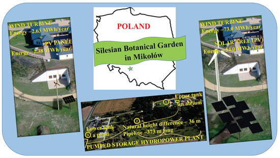
3.3.1. First Conception

The first conception (Figure 5a) assumed the creation of a small installation that (1) would not interfere with the landscape of Sośnia Góra, (2) would be characterized by small dimensions and a compact structure, and (3) would comprise wind turbine and a PV panel that would produce a similar amount of electricity. Therefore, an on-grid solution was proposed with an installation connected to an external electric grid, including the following:
  • SWIND 3200 horizontal axis wind turbine with: (1) a rated power (Pt) of 3.2 kW (for a rated wind speed equal to 10.8 m/s), (2) a maximum power (Pmax) of 4.0 kW (for cut-out wind speed equal to 15 m/s), (3) a cut-in wind speed (vstart) of 2.8 m/s, (4) a blade diameter of 3.5 m, and (5) a tower height of 12.0 m [85].
  • a PV panel with a total size of 5.0 × 4.0 m, containing a set of 10 polycrystalline modules NBJ-250P (1950 × 990 × 50 mm each) with 72 photovoltaic cells (156 × 156 mm each), with a rated power of 250 W (for a single cell) [86], mounted along with the tracker on a 5 m high column.
The annual energy production (Ew) from a horizontal axis wind turbine can be estimated according to Equation (1):
E w = S * P t * t = 2.63   MWh / year
where Ew is the annual energy production from a wind turbine operating under existing wind conditions, S is the total degree of the nominal power (Pt) of the turbine presented in Table 3 (S = 9.37%), Pt is the rated power of the SWIND 3200 turbine (Pt = 3.2 kW), and t is the time period (t = 24 h × 365 days).
The annual energy production (Es) from a PV panel can be estimated according to Equation (2):
E s = U * A * n * η * φ = 2.38   MWh / year
where, Es is the annual energy production from a PV panel operating under existing insolation conditions, U is the energy efficiency of 1 m2 of the surface perpendicular to the sun’s rays (U = 1220 kWh/m2 per year), A is the area of one PV module (A = 2.0 m × 1.0 m = 2.0 m2), n is the number of PV modules with photovoltaic cells (n = 10), η is the efficiency of photovoltaic cells (η = 0.13), and φ is the safety factor that takes into account the heterogeneity of atmospheric conditions (φ = 0.75).
In summary, the on-grid devices would produce a total of energy (Etot) equal to Equation (3):
E t o t = E w + E s = 5.01   MWh / year
which represents approximately 4.0% of CEEE’s total electricity demand. In such a situation, this solution would perform a more educational and demonstrative function for the society than the actual source of energy.
Additionally, the cost of the investment (Cinv) and the time of its amortization (Tamort) were estimated. For this purpose, were taken into account in the calculations: (1) the cost of building a wind turbine, which includes the purchase of a turbine with equipment and a tower, the installation of the turbine, the foundation building (Cwt = 32,300.00 PLN, where PLN is the abbreviation for Poland’s official currency, the Polish złoty), (2) the cost of building a photovoltaic panel, which includes the purchase of PV modules with equipment and a solar-tracker, the montage of all the elements and their configuration, the foundation and column building (Cpv = 21,600.00 PLN), (3) the cost of purchasing energy (energy produced by the RESs installation) by the energy company (Ce,res = 158.14 PLN/MWh), and (4) the cost of selling green certificates (energy origin certificates) (Cgc = 216.00 PLN/MWh).
Finally, according to Equations (4) and (5), the estimated total expenses and amortization period were as follows:
C i n v = C w t + C p v = 53 , 900.00   PLN
where Cwt is the total cost of the wind turbine (without the cost of the terrain), Cpv is the total cost of the PV panel (without the cost of the terrain)
T a m o r t = C i n v E t o t * ( C e , r e s + C g c ) = 32   year
where Etot is the total energy produced by the RES installation, Ce,res is the cost of purchasing energy from RESs, Cgc is the cost of selling energy origin certificates.

3.3.2. Second Conception

The second conception (Figure 5b) assumed the creation of an installation that would fully satisfy the demand for electricity in the Garden. Therefore, an on-grid solution was proposed with an installation connected to an external electric grid, including the following:
  • Zefir D21-P70-T18 horizontal axis wind turbine with: (1) a rated power (Pt) of 70 kW (for rated wind speed equal to 9.6 m/s), (2) a maximum power (Pmax) of 78.0 kW (for cut-out wind speed equal to 10 m/s), (3) a cut-in wind speed (vstart) of 3.0 m/s, (4) a blade diameter of 21.0 m, and (5) a tower height of 30.0 m [87].
  • Nine PV panels each containing 24 polycrystalline modules NBJ-250P (1950 × 990 × 50 mm each), with 218 photovoltaic cells (156 × 156 mm each), with a rated power of 250 W (for a single cell) [86], mounted along with trackers on a specially designed tree-shaped supporting structure, consisting of an 18 m high support column and eight branches with lengths of 9.57 m to 12.04 m [77].
According to Equations (1) and (2), the annual energy production from a wind turbine was estimated as Ew = 73.0 MWh/year, and the annual energy production from photovoltaic panels was estimated as, approximately, Es = 54 MWh/year. The following values were assumed for the calculations: S = 14.32% (according to Table 3), Pt = 70 kW, U = 1220 kWh/m2 per year, A = 6.0 m × 8.0 m = 48.0 m2, n = 9, η = 0.13, and φ = 0.75.
This solution would fully meet the Garden’s energy demand. As the second conception is part of the third proposition, a full cost analysis was performed for the third conception.

3.3.3. Third Conception

The third conception is an off-grid solution with an autonomous installation, not connected to the electric grid, including: (1) a set as the one seen in the second conception, and (2) additionally, for storing surplus energy: (a) a pumped storage hydropower plant (PSHP) with a Deriaz water turbine [88], and a reservoir with a volume of 4320 m3 (20 m × 20 m × 10.8 m (Section 4.4), or (b) a Jenox Heavy Duty 200 Ah 12 V battery [89] with a storage building.
The idea of integrating different energy sources in one hybrid system (solar–wind–hydro) has become popular because the different systems can compensate for each other’s irregularities [90]. Such hybrid systems are often combined with batteries, especially in off-grid applications. However, it should be kept in mind that the batteries are the most expensive component with the shortest life span in hybrid RES systems [91]. In the case under consideration, with an average daily energy consumption of Eday = 361.11 kWh/day, and an accumulator capacity equal to C = 2.4 kWh, the required battery would have to contain 151 accumulators. Due to the progressive decrease in the efficiency of batteries, the necessity to replace them after approximately 10 years of use must be taken into account. Therefore, the estimated cost of the third proposal with rechargeable batteries is PLN 2,700,000.00 (including the total cost of the wind turbine Cwt = PLN 1,000,000.00, the total cost of the PV panels Cpv = PLN 550,000.00, and the total cost of the batteries Cbat = PLN 1,150,000.00), with an amortization period of 47.4 years. The cost of the third proposal with the construction of a pumped storage hydropower plant is similar and equals PLN 2,750,000.00 (including the cost Cwt = PLN 1,000,000.00, the cost Cpv = PLN 550,000.00, and the total cost of the PSHP Cpshp = PLN 1,200,000.00), with an amortization period of 48.3 years.
Ultimately, it was concluded that choosing a pumped storage hydropower plant would be more environmentally friendly than using batteries, especially since the terrain configuration allows it.

3.3.4. Selection of the Conception

Ultimately, after consultation and approval from the director of the SBG and the mayor of the Mikołów commune, the third conception was selected for further analytical and numerical analyses. The design analysis was carried out for the structure of a wind turbine with a capacity of 70.0 kW and a specially shaped supporting structure for photovoltaic cells, including an energy storage in the form of a pumped storage power plant. The main arguments for this choice are as follows: (1) the system meets 100% of the energy demand for the Garden; (2) the devices fit perfectly into the landscape of the Garden (wind turbine up to 30 m, photovoltaic cells in a tree composition, hydroelectric power plant using the natural height difference occurring in the area of Sośnia Góra—approximately 36 m—and a natural water reservoir located in the northern part of the SBG’s area).

4. Results and Discussion

The author of this study would like to draw attention to the fact that the selection of appropriate devices depends on the criteria imposed by the SBG and technical data from the devices’ producers. Additionally, the geotechnical conditions of the subsoil could only be evaluated on the basis of the documentation shared by the Mikołów commune. Nevertheless, the presented analysis is complete, and although it was carried out only by geotechnical engineers and students, it covers all issues.

4.1. Soil-Water Conditions

For the needs of the earlier construction of the CEEE’s building, geotechnical documentation [92] was developed. On the basis of it, the geotechnical parameters of the soil that exist in the SBG’s area were determined. In the analyzed area, five boreholes were made to a depth of approximately 4.5 m, which allowed three geotechnical layers to be separated:
  • Mainly semi-solid silty clays and sandy clays (about 0.7 m below the surface);
  • Semi-solid and solid clays;
  • Deeper (below 4.5 to 5.0 m), a soft rock (limestone), strongly fractured, with a compressive strength up to 5 MPa.
No groundwater was found in any of the drilled boreholes. Due to the type of structures designed and geotechnical conditions, the second geotechnical category was established.
SIMPLIFICATIONS: The strength parameters of the soil were determined using correlation methods in accordance with the Polish standard [93]. Considering the small thickness (about 0.7 m) of the subsurface layer of silty and sandy clays and the fact that limestone was not found in every borehole, it was decided to treat the subsoil as homogeneous, consisting of clays.
It is worth noting that at the conception stage, the assumptions made are correct. However, in the case of the real geotechnical design of the foundations for a wind turbine and the supporting structure of a photovoltaic panel system, it would be necessary to identify the subsoil to a much greater depth based on detailed laboratory tests (for example, precise triaxial tests and tests in resonance columns) and in situ tests (static and dynamic probings).
Properly performing the reconnaissance of soil-water conditions determines the scope of the future foundations’ design procedures at the specific location of the construction. The real geotechnical parameters determined are used for: (1) numerical analyses [94,95], (2) choosing a possible soil improvement technology if necessary [94,96], (3) designing shallow foundations [97,98], and (4) designing deep foundation on piles/monopiles [99]. In the case of pile foundations/monopiles/tubular pipe piles, control static and/or dynamic load tests are an important element in verifying their correct design and construction [100,101,102]. Researchers also point to the need for the constant monitoring of soil conditions and groundwater level at the execution stage (including the effects of earthworks) and at the stage of using the structure (long-time maintenance) [95].

4.2. Shape of the Designed Structures and the List of Loads

On the basis of the previously presented conceptions, the design solutions for the load-bearing elements of devices considered for the production of energy from renewable sources were proposed. The cross-sections of these elements were selected according to the internal forces occurring in the structure as a result of the interactions resulting from permanent, environmental, and live as well as dynamic loads. All values were determined in accordance with the recommendations of Polish Standards and Eurocode [93,103,104,105,106,107,108]. The static calculations of the wind turbine structure were performed using analytical methods, while the supporting structure of the photovoltaic cells was performed using the numerical method in the Autodesk Robot program [77].

4.2.1. Wind Turbine

At the request of the SBG’s Director, to use a wind turbine not higher than 30 m (due to the landscape composition and the educational and recreational nature of the Garden), a 30 m high mast with a rotor diameter of 21 m was adopted for the design analysis. In the case of constant loads, the weight of the turbo-generator with nacelles, turntables, and columns was taken into account. In the case of variable loads, only the main wind load was taken into account for the most unfavorable load schema, which is the situation of blades’ failure in the event of a wind gust ‘from the behind’. The other dynamic interactions were omitted at the conception stage. However, it is worth remembering that in the case of offshore wind turbines, apart from wind loads, the loads induced by waves, inertia, and gravity that additionally force the use of appropriate methods of anchoring the floating supporting structures are also important. These effects are intensively analyzed by Polish researchers on offshore wind farms on the Baltic Sea, in the Polish Exclusive Economic Zone [99,109]. In turn, the natural frequencies of the system as a whole, including the foundation, tower, generator, and rotor are usually given by the turbine manufacturer in the form of imposed load values for a specific turbine model.
Ultimately, the values of the computational forces transferred to the foundation of the wind turbine are as follows:
  • Combination (54): bending moment M = 2972.0 kNm, horizontal force H = 112.0 kN, normal force Vx = 327.0 kN;
  • Combination (55): bending moment M = 4182.0 kNm, horizontal force H = 159.0 kN, normal force Vx = 278.0 kN.
A detailed analysis of all load schemes can be found in Ćwirko and Jastrzębska’s work [110].

4.2.2. Hybrid System—Supporting Structure with Photovoltaic Panels and Tracker

A set of photovoltaic panels with the necessary power of 54 kW (a specific energy demand at the SBG) would have to consist of 24 modules with 218 cells in each. Their positioning in traditional technology would cover an area of about 0.5 ha. It is economical and reasonable to design a tree-shaped structure consisting of the main bearing column and eight additional branches extending from it. In total, the installation of a tracker and nine panels, consisting of 24 polycrystalline modules, was mounted on a tree-structure. The designed screens are 8.00 × 6.00 m each. Many factors were taken into account during arranging of the screens, the most important of which were: (1) the lack of mutual shading of the screens on the day with the lowest angle of the sun’s rays equal to 14°15″, and (2) the possibility of free movement of the screens in relation to each other and to the sun’s rays (Figure 6a).
The climatic effects (such as wind, snow, icing, temperature) and the influences from the use of the construction (the installation and maintenance of devices) were taken into account in the list of loads. Each case was analyzed in two directions of wind operation. In addition, three possible screen arrangements and related models of structure operation were taken into account [77,111]:
  • Work of the construction as an array;
  • Work of the structure as a plane with a 45-degree slope;
  • Work of the structure as a plane with a 0-degree slope.
The cross-sections of structural elements were selected by means of a static-strength analysis and modal analysis in Autodesk Robot Structural Analysis Professional program for 128 load schemes (Figure 6b). Finally, the supports (branches) were made of a round steel pipe DE 457.0 × 40 mm, while the supporting column was made of a DE 1219.0 × 70 mm pipe [77,111].
Ultimately, the values of the computational forces transferred to the foundation of the supporting structure for photovoltaic panels are as follows:
  • Combination (48): bending moments My = 7.4 kNm and Mz = 30,202.0 kNm, horizontal force Hy = 1866.0 kN, normal force V = 974.0 kN;
  • Combination (124): bending moments My = 28,122.0 kNm and Mz = 20.1 kNm, horizontal force Hz = 1728.0 kN, normal force V = 937.0 kN.
A detailed analysis of all load schemes can be found in Ćwirko and Piotrowicz’ work [77].

4.3. Foundation of the Structure

The foundations’ design was the next stage considered with the wind turbines and supporting structures for the PV panels. Due to the good soil-water conditions, a direct foundation was taken into account. Additionally, alternative solutions in the form of monopile and micropile were proposed. This type of foundation allows one to reduce the scope of foundation works and limit the interference with the SBG’s ecosystem. The settlement of both structures (wind turbine and “PV-tree”) was estimated by numerical analysis in the Z_Soil program. Calculations related to the reinforcement of foundations have been presented in detail by Ćwirko and Piotrowicz [74]. The subsoil parameters were adopted on the basis of the geotechnical documentation provided by the Mikołów commune [92], while the load system was determined according to Section 4.2.

4.3.1. Foundation of a Wind Turbine

The numerical model of the foundation was made in the Z_Soil program. The foundation and the subsoil were modeled in the form of a three-dimensional mesh of finite elements, using the symmetry of the entire arrangement. The individual stages of foundation construction were recreated using the existence function. The geometry of the numerical model with division into finite elements and the stages of foundation execution are presented in Figure 7.
The following parameters were adopted in the model:
  • For soil (clay): oedometric compressibility modulus M0 = 25.0 MPa, Poisson’s ratio ν = 0.37, unit weight γ = 21.5 kN/m3, internal friction angle φ = 13°, soil cohesion c = 60.0 kPa, and dilatation angle ψ = 2.0°;
  • For concrete: deformation modulus E0 = 31.0 GPa, Poisson’s ratio ν = 0.20, and unit weight γ = 25.0 kN/m3.
Finally, to optimize the foundation costs of a wind turbine, a circular footing with the following dimensions was integrated (Figure 8):
  • Depth of the foundation—D = 1.80 m;
  • Radius of the column—r = 1.00 m;
  • Radius of the footing—R = 3.25 m;
  • Thickness of the footing—h = 0.80 m.
The foundation of the wind turbine on a monopile was proposed as an alternative solution. This proposal refers to solutions used in offshore power plants. The calculations of a single pile were made in accordance with the standard [104]. Finally, the following dimensions of the pile were adopted (Figure 8b):
  • Pile diameter d = 2.0 m (an analogous to the shaft of the foundation);
  • Pile length from ground level h = 13.0 m;
  • Concrete type C25/30 with compressive strength equal to 25 MPa [112];
  • Manufacturing technology—the large-diameter bored pile with a temporary (recoverable) steel casing.
It is worth noting that this alternative foundation method could possibly be used as a heating foundation using the temperature of the surrounding ground (low-temperature geothermal energy) and cooperating with a heat pump [1]. Examples of such solutions are described by Brandl [113]—the system of energy piles in the sidewalls of the Lainzer Tunnel; Amatya et al. [114]—the energy piles used in the Rehabilitation Center in Bad Schallerbach in Austria; Von der Hude and Kapp [115]—the energy piles used for the foundation of the Main Tower building in Frankfurt am Main; and Bouazza et al. [116]—the use of heat exchanger piles in the area of Monash University in Australia.

4.3.2. Foundation of a Supporting Structure for Photovoltaic Panels and a Tracker

The obtained load values transmitted from the supporting column to the foundation indicate the action of forces on a large eccentricity. Therefore, it was decided to use a direct foundation on a circular footing. The numerical 3D model of the foundation was made in the Z_Soil program. It consisted of 6593 nodes (Figure 9a) and represented the entire structure during various stages of the foundation execution: excavation, reinforced concrete foundation, and backfill.
The following parameters were adopted in the model:
  • For soil (clay): oedometric compressibility modulus M0 = 25.0 MPa, Poisson’s ratio ν = 0.37, unit weight γ = 21.5 kN/m3, internal friction angle φ = 13°, soil cohesion c = 60.0 kPa, and dilatation angle ψ = 2.0°;
  • For concrete: deformation modulus E0 = 35.0 GPa, Poisson’s ratio ν = 0.20, and unit weight γ = 25.0 kN/m3.
Finally, in order to optimize the foundation costs of the PV construction, a circular footing was adopted with the following dimensions: radius of the footing R = 5.30 m, depth of the foundation D = 3.30 m, and thickness of the footing h = 1.60 m.
The foundation of the PV-supporting structure consists of: (1) A total of 24 TITAN 130/60 micropiles with a length of 17.5 m (16.0 m active length + 1.5 loose length), and (2) a square pile cap with dimensions of 5 × 5 × 1 m, which was proposed as an alternative solution (according to standards [77,108]). The numerical model for this proposition is presented in Figure 9b.

4.4. Conception of a Pumped Storage Power Plant

A pumped storage power plant (PSPP) is a type of hydroelectric energy storage. Its work is based on moving water between two reservoirs located at different elevations (i.e., an upper and lower reservoir). The power is generated when the water moves down from one to the other reservoir (discharge), passing through a pump-turbine, i.e., a device that can operate as a pump and as a turbine. The direction of the water flow (up or down) depends on the time of day, electricity demand, and the occurrence of its surplus or deficiency. This is especially significant in the case of installations based on renewable energy sources (RESs) which are susceptible to weather conditions. Wind and photovoltaic (PV) systems are characterized by uncertainties and large fluctuations in power production, which affect grid stability and reliability. Therefore, the off-grid systems [118] are often combined with hydro energy, which can reduce seasonal and inter-day fluctuations [119,120]. A pumped storage power plant, in particular, can perform this function because it can start and stop in a short time, generate different levels of power, and store energy [121]. The efficiency of such power plants is practically unlimited. It depends only on the volume of the reservoir and does not change over time. Water moves in a closed circuit, and the losses resulting from the evaporation process are negligible. The small size of the water reservoir does not have to be a disadvantage during the energy exchange between the microgrid and the power system, as demonstrated by Zhang et al. [122] and Jurasz and Ciapała [123]. For the proper study of pumped storage power plants, it is necessary to obtain an appropriate gradient, which allows for the effective use of the flowing water. Places that have a natural difference in ground levels (such as the Sośnia Góra area of the Silesian Botanical Garden) are the best solution (Figure 10).

4.4.1. Selection of a Water Turbine

The hybrid installation proposed for the Garden consists of a wind turbine and of photovoltaic cells with a tracker, mounted on a specially shaped support structure. These renewable energy sources mainly depend on wind and sun. Therefore, if there was no power, the hydropower plant would take over the full production of electricity, mainly on windless nights. For this reason, the power of the turbine should be selected so that this is made possible.
Accordingly, the use of a Deriaz turbine has been proposed [124,125,126]. It is a type of reaction turbine, i.e., one in which the pressure of the water driving the turbine exceeds the atmospheric pressure and decreases with the flow through the elements of the turbine. In this case, both the water pressure energy and the kinetic energy of the flowing water are used. In addition, it can act as both a hydraulic pump and a hydraulic turbine. Moreover, this turbine can work with slight slopes on the terrain, even if they are only 13 m. Another very popular Francis turbine is more suitable in the case of a much larger difference in level (up to 500 m). It is also much more expensive. When selecting a Deriaz turbine, this economic aspect is also important. Finally, based on the analysis performed, it was found that the required power of the turbine is 15.05 kW [77] and, therefore, a turbine with the following parameters was selected: power—20 kW, head—20 to 50 m, flow rate—0.05 m3/s, rotation speed—300 prm, and mass—1.3 t [88].

4.4.2. Analysis of the Required Energy Capacity—The Water Reservoirs

When designing a pumped storage plant, it is necessary to determine its energy capacity. It must be selected in such a way so as to minimize, to an acceptable level, the possibility of a power failure in any given period.
It was assumed in the presented concept that the power plant should provide an uninterrupted possibility of returning energy during one day, with full coverage of the energy demand of the SBG’s area and the CEEE’s building. This time was determined on the basis of the analysis of the long-term measurements of climatic conditions (Section 3). The purpose of the analysis was not only to determine the amount of energy that can be obtained from the designed installation, but also to find a period of time during which energy production is insufficient for the normal functioning of the Garden, due to unfavorable weather conditions. Weather observations also show that the amount of energy produced by the ‘PV cells–wind turbine’ system is sufficient and ensures the stable and efficient operation of the pumped storage power plant [77]. Other elements to consider include: the technological possibilities of water reservoirs’ execution; the possibility of using an available-surface area of the SBG; the existence of an actual level difference between the upper and lower reservoirs.
In the presented conception, the pond at the base of Sośnia Góra fulfills the function of a lower reservoir. However, such a solution requires a thorough environmental analysis regarding the impact of large, periodic changes in the water level on the pond ecosystem and the functioning of the entire Garden, whereas the atrium located within the CEEE’s building was selected for the location of the upper reservoir, as seen in Figure 11. As a result, additional interference with the Garden’s ecosystem is limited and the greatest difference in terrain levels is used.
This location has some disadvantages despite its many advantages. First of all, it does not allow one to increase the volume of the upper reservoir by increasing horizontal dimensions (length and width), due to the limited area that can be used. On the other hand, increasing the depth of this reservoir will reduce the difference in levels between the bottom of the upper reservoir and the surface of the lower reservoir. Another difficulty is the load associated with the additional ground pressure on the walls of the upper reservoir, caused by the effects transmitted by the strip footings of the CEEE’s building. The resulting plot of soil pressure on the reservoir wall is presented in Figure 12.
A minimum water flow of 0.05 m3/s must be ensured so that the selected turbine works efficiently. As a result, the tank volume should be equal to 4320 m3. As the atrium is square with a side size of 20 m, the depth of the reservoir should be 10.8 m [77].
In the analysis of internal forces, the following design cases were taken into account:
  • An empty reservoir loaded with the soil pressure (the most unfavorable load system);
  • A full reservoir loaded with the hydrostatic pressure of water on one side, and with the soil pressure on the other side;
  • A partially full reservoir.
  • Finally, the internal forces were determined in the Autodesk Robot Structural Analysis Professional program. The values of bending moments in the structure are shown in Figure 13. Due to its specific localization, a diaphragm-walls technology was proposed to construct the reservoir under-ground. After the construction works are completed, it is possible to recreate the original surface from paving stones in the atrium.

4.4.3. Pressure Pipeline

A pressure pipeline, connecting the upper and lower reservoirs and used to transport the water between them, is an inseparable element of the pumped storage power plant. Its geometric dimensions depend on the parameters of the water turbine used, the difference in levels between the upper and lower reservoirs, and the distance between them, as well as the material from which the pipeline is made.
Taking into account the specificity and configuration of the area of Sośnia Góra, a 373 m long underground pipeline has been proposed (Figure 10). Based on the analysis of the issue, it was found that: (1) the maximum water pressure cannot exceed 353.4 kPa; (2) using the high-density polyethylene (PEHD) pipes with a low absolute roughness coefficient equal to k = 0.01 mm [127] is most optimal at such pressures, making it possible to limit the pressure losses related to the flow of the medium through the pipeline; (3) the maximum unit pressure losses are equal to 124.9 Pa/m.
Finally, according to standard [128], the installation of PE 100, SDR 17, 200 × 11.9 mm pipes (dn × en, where dn is a pipe outer diameter, and en is a wall thickness) was proposed. Due to the fact that the pipeline will be an underground installation, it will be necessary to use the directional drilling technology that minimizes interference in the garden’s ecosystem. The proposed technology requires the use of RC-type reinforced pipes, which have a polypropylene protective layer that reduces the friction between the soil and the pipe and protects the pipes against damage during drilling.

5. Conclusions

This study presents the specificity of the Silesian Botanical Garden (SBG) and the recreational, educational, and pro-ecological functions it performs in the Silesian community, as well as in the protection of biodiversity in the Silesia area in Poland. The presented project meets three out of five assumptions (covering the following sectors: water management, energy consumption, carbon consumption, waste, compost and recycling, sustainable food) concerning the sustainability incorporation actions in the Garden’s area [68]. The employees and students of the Faculty of Civil Engineering at the Silesian University of Technology in Gliwice proposed three conceptions for the use of renewable energy sources (RESs) in the SBG’s area: (1) an on-grid solution with an annual energy production of 5 MWh, (2) an on-grid solution with an annual energy production of 130 MWh, and (3) an off-grid solution with an annual energy production of 130 MWh containing either batteries or a pumped storage hydropower plant. The basic criteria of the designed solutions were specified by the Director of the SBG and the mayor of the Mikołów commune. The main conclusions drawn from the detailed analysis of various conceptions proposed for the Sośnia Góra area in the Silesia Botanical Garden are as follows:
  • Despite the fact that renewable energy production devices provide general guidelines regarding their loads, foundations, etc., depending on the situation (values of loading forces, soil and water conditions, topography, climatic conditions, energy demand), the persons responsible for the project should perform an independent detailed case study with calculations using, e.g., the finite element method. For this purpose, the cooperation of many specialists, including geotechnical/electrical/mechanical/aerodynamic engineers and climatologists, among others, is necessary;
  • Another important conclusion concerns the detailed analysis of local weather conditions (wind conditions, insolation) and the topography. Climatic data should preferably come from a period of several years and correspond to the expected location of RESs devices, including height above the ground surface;
  • A good recognition of soil-water conditions (an important function of a geotechnical engineer) is necessary not only for the correct foundation of RESs devices subjected to high loads from wind, temperature, and snow. Knowing the subsoil is essential if the use of geothermal energy from the soils or rocks is being considered. The foundation of the wind turbine on a monopile allows it to be treated as a heating foundation. In addition, a wind turbine or other renewable energy systems can be used to directly supply the heat pump with electricity;
  • The off-grid solution with an autonomous installation, not connected to the electric grid, includes: (1) a Zefir D21-P70-T18 wind turbine with a power of 70 kW and a height of 30 m; (2) a set of 218 polycrystalline NBJ-250P photovoltaic cells with a total power of 54.0 kW and dimensions of each element equal to 1.65 × 0.99 m that, along with the tracker, are mounted on a specifically designed tree-shaped supporting structure, consisting of a support column and the eight branches; and (3) additionally, to store surplus of energy, a pumped storage power plant with: (a) a Deriaza water turbine, (b) an upper reservoir with a volume of 4320 m3 (20 m × 20 m × 10.8 m), and (c) a natural pond as a lower reservoir. This solution meets all the requirements for the Silesian Botanical Garden;
  • The proposed hybrid system which may be called a Solar tree (in this case, a tree-like supporting structure with photovoltaic cells as foundation) can be considered a base solution, but its final shape and total power will depend on specific conditions (location and energy demand) and detailed analyses. Indeed, similar initiatives are carried out elsewhere in the world, but the solar trees are still perceived as “futuristic”. The 18 most iconic giant solar supertrees (up to 50 meters above ground) in Singapore’s Gardens by the Bay are the best example of this [129]. It is worth mentioning the wind tree prototype designed by entrepreneur Jérôme Michaud-Larivière, which was first installed in Paris in December 2015. The innovative tree-like structure which is 12 m high and 7 m wide is composed of three steel trunks that stem into tinier branches on which the 36 leaf-shaped wind turbines are attached (the vertical-axis Savonius micro wind turbines 70 cm high called an “aero-leaf”). This solution is intended for both urban (mainly) and rural applications and is currently available in France [130]. Both the proposed solar tree and the wind tree of the NewWind company, as innovations, might lead to other ideas and technologies;
  • The analysis showed that even a slight difference in terrain levels make it possible to construct a pumped storage hydropower plant (PSHP). Furthermore, this PSHP can be perfectly integrated into the existing atrium of the building of the Center for Ecological and Environmental Education (CEEE) in Sośnia Góra. An interesting and innovative solution, which is the pilot project Gaildorf near Stuttgart in Bavaria (Germany), is worth mentioning [131,132]. The integrated fully automated system includes: (1) four wind turbines with heights of 150 to 223 m above sea level, rotor diameters of 103 to 137 m, and powers of 3.2 to 3.8 MW, as well as (2) a pumped storage hydropower plant in which (a) the foundations of the hybrid wind turbine towers also function as upper water reservoirs (a total of 160,000 m3 of water can be stored, and an energy capacity of 70 MWh is ensured), while (b) the lower tank is a natural water Gaildorf-Unterrot reservoir in the Kochertal valley at a distance of 3.2 km (200 m in the vertical line), connected to the hybrid towers by (c) the patented thermoplastic pipeline, and (d) equipped with reversible Francis turbines. This modern wind farm with innovative energy storage began its operation in 2018. Currently, ‘Hybrid Tower’ concepts are being implemented in the North American market, in Thailand, Japan, and Austria, making a significant contribution to climate protection and resource efficiency.
To summarize, the proposed conceptions take into account the specificity of the Silesian Botanical Garden in Mikołów. This possibility is not offered by the specifications delivered with the RESs devices. Elaborated renewable energy systems interfere with the landscape and ecosystem as little as possible. Moreover, they can perform an educational function in society. Another example of the integrated function of a botanical garden and renewable energy sources is the Brera Botanical Garden in Milan, where Plenitude’s “Feeling the Energy” installation, which was created in the context of the “Design Regeneration” exhibition, was presented. “Feeling the Energy” is an installation dedicated to the many forms of energy (such as sound, light, and wind) that gives visitors a multisensory experience of the ways in which the energy around us can be perceived through the five senses. An additional advantage of the solutions used is the fact that the energy stored during the day can be used to light up the Brera’s Garden during evening hours and to power water vaporizers that will cool the Garden while also feeding the surrounding plants. It is worth emphasizing that Plenitude’s company, dedicated to the deployment of charging infrastructure for electric mobility, undertakes activities related to strengthening the synergy between nature, people, and cities. Such action reflects the strategic commitment of Plenitude in the energy transition and its perception by society [133].
Similar activities were undertaken at the Silesian Botanical Garden in Mikołów (Poland), although on a smaller scale. The presented project is currently at the concept stage. The selection of specific devices and materials as well as the accurate design of the proposed solutions will be made in the future after obtaining financing by the SBG’s authorities. Perhaps the scope of this study will be expanded later.

Funding

This research received no external funding.

Institutional Review Board Statement

Not applicable.

Informed Consent Statement

Not applicable.

Data Availability Statement

Not applicable.

Acknowledgments

The author would like to express her gratitude to Paweł Kojs, Director of the Silesian Botanical Garden and mayor of the Mikołów commune, who collaborated on the concepts and provided the necessary information as well as shared many materials related to the Silesian Botanical Garden. Additionally, the author would like to thank the students Marcin Ćwirko and Bartosz Piotrowicz for their valuable participation in the performance of all analyses.

Conflicts of Interest

The author declare no conflict of interest.

References

  1. Jastrzębska, M.; Wawrzyńczyk, B. The Analysis of The Direct Foundation with Energy Foundations on the Basis of The Office Building “A4 Business Park” In Katowice at Francuska Street. Arch. Civ. Eng. Environ. 2016, 9, 65–76. [Google Scholar] [CrossRef]
  2. Benedek, J.; Sebestyén, T.-T.; Bartók, B. Evaluation of renewable energy sources in peripheral areas and renewable energy-based rural development. Renew. Sustain. Energy Rev. 2018, 90, 516–535. [Google Scholar] [CrossRef]
  3. Wang, Y.; Sun, T. Life cycle assessment of CO2 emissions from wind power plants: Methodology and case studies. Renew. Energy 2012, 43, 30–36. [Google Scholar] [CrossRef]
  4. Schreiber, A.; Marx, J.; Zapp, P. Comparative life cycle assessment of electricity generation by different wind turbine types. J. Clean. Prod. 2019, 233, 561–572. [Google Scholar] [CrossRef]
  5. Smoucha, E.A.; Fitzpatrick, K.; Buckingham, S.; Knox, O.G.G. Life Cycle Analysis of the Embodied Carbon Emissions from 14 Wind Turbines with Rated Powers between 50 Kw and 3.4 Mw. J. Fundam. Renew. Energy Appl. 2016, 6, 1000211. [Google Scholar] [CrossRef]
  6. Chandrasekharam, D.; Ranjith Pathegama, G. CO2 emissions from renewables: Solar pv, hydrothermal and EGS sources. Géoméch. Geophys. Geo-Energy Geo-Resour. 2020, 6, 13. [Google Scholar] [CrossRef]
  7. Chowdhury, M.D.S.; Rahman, K.S.; Chowdhury, T.; Nuthammachot, N.; Techato, K.; Akhtaruzzaman, M.D.; Tiong, S.K.; Sopian, K.; Nowshad Amin, N. An Overview of Solar Photovoltaic Panels’ End-of-life Material Recycling. Energy Strategy Rev. 2020, 27, 100431. [Google Scholar] [CrossRef]
  8. Włodarczyk, R. Analysis of the Photovoltaic Waste-recycling Process in Polish Conditions—A Short Review. Sustainability 2022, 14, 4739. [Google Scholar] [CrossRef]
  9. Schoden, F.; Dotter, M.; Knefelkamp, D.; Blachowicz, T.; Schwenzfeier Hellkamp, E. Review of State of the Art Recycling Methods in the Context of Dye Sensitized Solar Cells. Energies 2021, 14, 3741. [Google Scholar] [CrossRef]
  10. Taras, P.; Nilifard, R.; Zhu, Z.-Q.; Azar, Z. Cooling Techniques in Direct-Drive Generators for Wind Power Application. Energies 2022, 15, 5986. [Google Scholar] [CrossRef]
  11. Wang, W.; Xue, Y.; He, C.; Zhao, Y. Review of the Typical Damage and Damage-Detection Methods of Large Wind Turbine Blades. Energies 2022, 15, 5672. [Google Scholar] [CrossRef]
  12. Le, T.-C.; Luu, T.-H.; Nguyen, H.-P.; Nguyen, T.-H.; Ho, D.-D.; Huynh, T.-C. Piezoelectric Impedance-Based Structural Health Monitoring of Wind Turbine Structures: Current Status and Future Perspectives. Energies 2022, 15, 5459. [Google Scholar] [CrossRef]
  13. Farhat, H.; Salvini, C. Novel Gas Turbine Challenges to Support the Clean Energy Transition. Energies 2022, 15, 5474. [Google Scholar] [CrossRef]
  14. Jaen-Cuellar, A.Y.; Elvira-Ortiz, D.A.; Osornio-Rios, R.A.; Antonino-Daviu, J.A. Advances in Fault Condition Monitoring for Solar Photovoltaic and Wind Turbine Energy Generation: A Review. Energies 2022, 15, 5404. [Google Scholar] [CrossRef]
  15. Gambier, A. Multiobjective Optimal Control ofWind Turbines: A Survey on Methods and Recommendations for the Implementation. Energies 2022, 15, 567. [Google Scholar] [CrossRef]
  16. Malliotakis, G.; Alevras, P.; Baniotopoulos, C. Recent Advances in Vibration Control Methods for Wind Turbine Towers. Energies 2021, 14, 7536. [Google Scholar] [CrossRef]
  17. Benbouzid, M.; Berghout, T.; Sarma, N.; Djurović, S.; Wu, Y.; Ma, X. Intelligent Condition Monitoring of Wind Power Systems: State of the Art Review. Energies 2021, 14, 5967. [Google Scholar] [CrossRef]
  18. Lu, L.; Zhu, M.; Wu, H.; Wu, J. A Review and Case Analysis on Biaxial Synchronous Loading Technology and Fast Moment-Matching Methods for Fatigue Tests of Wind Turbine Blades. Energies 2022, 15, 4881. [Google Scholar] [CrossRef]
  19. Pacheco, J.; Pimenta, F.; Pereira, S.; Cunha, Á.; Magalhães, F. Fatigue Assessment of Wind Turbine Towers: Review of Processing Strategies with Illustrative Case Study. Energies 2022, 15, 4782. [Google Scholar] [CrossRef]
  20. Krajewski, D.; Oleksy, M.; Oliwa, R.; Bulanda, K.; Czech, K.; Mazur, D.; Masłowski, G. Methods for Enhancing the Electrical Properties of Epoxy Matrix Composites. Energies 2022, 15, 4562. [Google Scholar] [CrossRef]
  21. Olubamiwa, O.I.; Gule, N. A Review of the Advancements in the Design of Brushless Doubly Fed Machines. Energies 2022, 15, 725. [Google Scholar] [CrossRef]
  22. Adkins, K.A.; Sescu, A. Wind Farms and Humidity. Energies 2022, 15, 2603. [Google Scholar] [CrossRef]
  23. Contreras Montoya, L.T.; Lain, S.; Ilinca, A. A Review on the Estimation of Power Loss Due to Icing in Wind Turbines. Energies 2022, 15, 1083. [Google Scholar] [CrossRef]
  24. Asim, T.; Islam, S.Z.; Hemmati, A.; Khalid, M.S.U. A Review of Recent Advancements in Offshore Wind Turbine Technology. Energies 2022, 15, 579. [Google Scholar] [CrossRef]
  25. Arredondo-Galeana, A.; Brennan, F. Floating Offshore Vertical Axis Wind Turbines: Opportunities, Challenges and Way Forward. Energies 2021, 14, 8000. [Google Scholar] [CrossRef]
  26. Rajpar, A.H.; Ali, I.; Eladwi, A.E.; Bashir, M.B.A. Recent Development in the Design of Wind Deflectors for Vertical Axis Wind Turbine: A Review. Energies 2021, 14, 5140. [Google Scholar] [CrossRef]
  27. Olabi, A.G.; Wilberforce, T.; Elsaid, K.; Salameh, T.; Sayed, E.T.; Husain, K.S.; Abdelkareem, M.A. Selection Guidelines for Wind Energy Technologies. Energies 2021, 14, 3244. [Google Scholar] [CrossRef]
  28. Mathern, A.; von der Haar, C.; Marx, S. Concrete Support Structures for Offshore Wind Turbines: Current Status, Challenges, and Future Trends. Energies 2021, 14, 1995. [Google Scholar] [CrossRef]
  29. Sattar, M.; Rehman, A.; Ahmad, N.; Mohammad, A.-S.; Al Ahmadi, A.A.; Ullah, N. Performance Analysis and Optimization of a Cooling System for Hybrid Solar Panels Based on Climatic Conditions of Islamabad, Pakistan. Energies 2022, 15, 6278. [Google Scholar] [CrossRef]
  30. Hasan, H.A.; Sherza, J.S.; Mahdi, J.M.; Togun, H.; Abed, A.M.; Ibrahim, R.K.; Yaïci, W. Experimental Evaluation of the Thermoelectrical Performance of Photovoltaic-Thermal Systems with a Water-Cooled Heat Sink. Sustainability 2022, 14, 10231. [Google Scholar] [CrossRef]
  31. Sornek, K.; Goryl, W.; Figaj, R.; Dąbrowska, G.; Brezdeń, J. Development and Tests of the Water Cooling System Dedicated to Photovoltaic Panels. Energies 2022, 15, 5884. [Google Scholar] [CrossRef]
  32. Hajjaj, S.S.H.; Aqeel, A.A.K.A.; Sultan, M.T.H.; Shahar, F.S.; Shah, A.U.M. Review of Recent Efforts in Cooling Photovoltaic Panels (PVs) for Enhanced Performance and Better Impact on the Environment. Nanomaterials 2022, 12, 1664. [Google Scholar] [CrossRef] [PubMed]
  33. Goudelis, G.; Lazaridis, P.I.; Dhimish, M. A Review of Models for Photovoltaic Crack and Hotspot Prediction. Energies 2022, 15, 4303. [Google Scholar] [CrossRef]
  34. Hopwood, M.W.; Stein, J.S.; Braid, J.L.; Seigneur, H.P. Physics-Based Method for Generating Fully Synthetic IV Curve Training Datasets for Machine Learning Classification of PV Failures. Energies 2022, 15, 5085. [Google Scholar] [CrossRef]
  35. Yu, J.; Yang, Y.; Zhang, H.; Sun, H.; Zhang, Z.; Xia, Z.; Zhu, J.; Dai, M.; Wen, H. Spectrum Analysis Enabled Periodic Feature Reconstruction Based Automatic Defect Detection System for Electroluminescence Images of Photovoltaic Modules. Micromachines 2022, 13, 332. [Google Scholar] [CrossRef]
  36. Yan, B.; Wu, Q.; Chi, X.; Wu, C.; Luo, P.; Luo, Y.; Zeng, P. Numerical and Experimental Investigation of Photovoltaic/Thermal Systems: Parameter Analysis and Determination of Optimum Flow. Sustainability 2022, 14, 10156. [Google Scholar] [CrossRef]
  37. Umam, M.F.; Hasanuzzaman, M.; Rahim, N.A. Global Advancement of Nanofluid-Based Sheet and Tube Collectors for a Photovoltaic Thermal System. Energies 2022, 15, 5667. [Google Scholar] [CrossRef]
  38. Kopecek, R.; Libal, J. Bifacial Photovoltaics 2021: Status, Opportunities and Challenges. Energies 2021, 14, 2076. [Google Scholar] [CrossRef]
  39. Pastuszak, J.; Węgierek, P. Photovoltaic Cell Generations and Current Research Directions for Their Development. Materials 2022, 15, 5542. [Google Scholar] [CrossRef]
  40. Arsalis, A.; Georghiou, G.E.; Papanastasiou, P. Recent Research Progress in Hybrid Photovoltaic–Regenerative Hydrogen Fuel Cell Microgrid Systems. Energies 2022, 15, 3512. [Google Scholar] [CrossRef]
  41. Gnida, P.; Amin, M.F.; Pająk, A.K.; Jarząbek, B. Polymers in High-Efficiency Solar Cells: The Latest Reports. Polymers 2022, 14, 1946. [Google Scholar] [CrossRef] [PubMed]
  42. Maafa, I.M. All-Inorganic Perovskite Solar Cells: Recent Advancements and Challenges. Nanomaterials 2022, 12, 1651. [Google Scholar] [CrossRef] [PubMed]
  43. Roy, P.; Ghosh, A.; Barclay, F.; Khare, A.; Cuce, E. Perovskite Solar Cells: A Review of the Recent Advances. Coatings 2022, 12, 1089. [Google Scholar] [CrossRef]
  44. Romeo, A.; Artegiani, E. CdTe-Based Thin Film Solar Cells: Past, Present and Future. Energies 2021, 14, 1684. [Google Scholar] [CrossRef]
  45. Hanifi, H.; Jaeckel, B.; Pander, M.; Dassler, D.; Kumar, S.; Schneider, J. Techno-Economic Assessment of Half-Cell Modules for Desert Climates: An Overview on Power, Performance, Durability and Costs. Energies 2022, 15, 3219. [Google Scholar] [CrossRef]
  46. Bogdanowicz, K.A. Bi-Triggering Energy Harvesters: Is It Possible to Generate Energy in a Solar Panel under Any Conditions? Energies 2021, 14, 5796. [Google Scholar] [CrossRef]
  47. Romaní, J.; Ramos, A.; Salom, J. Review of Transparent and Semi-Transparent Building-Integrated Photovoltaics for Fenestration Application Modeling in Building Simulations. Energies 2022, 15, 3286. [Google Scholar] [CrossRef]
  48. Marques Lameirinhas, R.A.; Torres, J.P.N.; de Melo Cunha, J.P. A Photovoltaic Technology Review: History, Fundamentals and Applications. Energies 2022, 15, 1823. [Google Scholar] [CrossRef]
  49. Nordin, N.A.; Ansari, M.N.; Nomanbhay, S.M.; Hamid, N.A.; Tan, N.M.L.; Yahya, Z.; Abdullah, I. Integrating Photovoltaic (PV) Solar Cells and Supercapacitors for Sustainable Energy Devices: A Review. Energies 2021, 14, 7211. [Google Scholar] [CrossRef]
  50. Ramos, H.M.; Vargas, B.; Saldanha, J.R. New Integrated Energy Solution Idealization: Hybrid for Renewable Energy Network (Hy4REN). Energies 2022, 15, 3921. [Google Scholar] [CrossRef]
  51. Kim, W.-J.; Lee, Y.-S.; Chun, Y.-H.; Jeong, H.-S. Reserve-Constrained Unit Commitment Considering Adjustable-Speed Pumped-Storage Hydropower and Its Economic Effect in Korean Power System. Energies 2022, 15, 2386. [Google Scholar] [CrossRef]
  52. Medveď, D.; Kolcun, M.; Pavlík, M.; Beňa, Ľ.; Mešter, M. Analysis of Prosumer Behavior in the Electrical Network. Energies 2021, 14, 8212. [Google Scholar] [CrossRef]
  53. Chaima, E.; Lian, J.; Ma, C.; Zhang, Y.; Kavwenje, S. Complementary Optimization of Hydropower with Pumped Hydro Storage–Photovoltaic Plant for All-Day Peak Electricity Demand in Malawi. Energies 2021, 14, 4948. [Google Scholar] [CrossRef]
  54. Storli, P.-T.; Lundström, T.S. A New Technical Concept for Water Management and Possible Uses in Future Water Systems. Water 2019, 11, 2528. [Google Scholar] [CrossRef]
  55. Cicėnas, P.; Radziukynas, V. Developed Transfer Function Allows Hydro Generators to Enter the Full Range of Ancillary Services Market. Energies 2022, 15, 397. [Google Scholar] [CrossRef]
  56. Wang, Y.; Fang, G. Joint Operation Modes and Economic Analysis of Nuclear Power and Pumped Storage Plants under Different Power Market Environments. Sustainability 2022, 14, 9128. [Google Scholar] [CrossRef]
  57. Zhang, Q.; Zheng, Y. Geotechnical Investigations and Support Design for an Underground Powerhouse of Pumped-Storage Power Station: A Case Study in Chongqing, China. Sustainability 2022, 14, 8481. [Google Scholar] [CrossRef]
  58. Chu, Y.; Pan, Y.; Zhan, H.; Cheng, W.; Huang, L.; Wu, Z.; Shao, L. Systems Accounting for Carbon Emissions by Hydropower Plant. Sustainability 2022, 14, 6939. [Google Scholar] [CrossRef]
  59. Pujades, E.; Poulain, A.; Orban, P.; Goderniaux, P.; Dassargues, A. The Impact of Hydrogeological Features on the Performance of Underground Pumped-Storage Hydropower (UPSH). Appl. Sci. 2021, 11, 1760. [Google Scholar] [CrossRef]
  60. Špano, M.; Říha, J.; Španová, A.; Šedo, O.; Rittich, B. Bacterial Diversity in the Asphalt Concrete Lining of the Upper Water Reservoir of a Pumped-Storage Scheme. Water 2020, 12, 3045. [Google Scholar] [CrossRef]
  61. Kobler, U.G.; Wüest, A.; Schmid, M. Effects of Lake–Reservoir Pumped-Storage Operations on Temperature and Water Quality. Sustainability 2018, 10, 1968. [Google Scholar] [CrossRef]
  62. Wessel, M.; Madlener, R.; Hilgers, C. Economic Feasibility of Semi-Underground Pumped Storage Hydropower Plants in Open-Pit Mines. Energies 2020, 13, 4178. [Google Scholar] [CrossRef]
  63. Kitsikoudis, V.; Archambeau, P.; Dewals, B.; Pujades, E.; Orban, P.; Dassargues, A.; Pirotton, M.; Erpicum, S. Underground Pumped-Storage Hydropower (UPSH) at the Martelange Mine (Belgium): Underground Reservoir Hydraulics. Energies 2020, 13, 3512. [Google Scholar] [CrossRef]
  64. Pujades, E.; Orban, P.; Archambeau, P.; Kitsikoudis, V.; Erpicum, S.; Dassargues, A. Underground Pumped-Storage Hydropower (UPSH) at the Martelange Mine (Belgium): Interactions with Groundwater Flow. Energies 2020, 13, 2353. [Google Scholar] [CrossRef]
  65. Lugauer, F.J.; Kainz, J.; Gehlich, E.; Gaderer, M. Roadmap to Profitability for a Speed-Controlled Micro-Hydro Storage System Using Pumps as Turbines. Sustainability 2022, 14, 653. [Google Scholar] [CrossRef]
  66. Wang, L.; Zhang, K.; Zhao, W. Nonlinear Modeling of Dynamic Characteristics of Pump-Turbine. Energies 2022, 15, 297. [Google Scholar] [CrossRef]
  67. Deng, Y.; Xu, J.; Li, Y.; Zhang, Y.; Kuang, C. Research on Energy Loss Characteristics of Pump-Turbine during Abnormal Shutdown. Processes 2022, 10, 1628. [Google Scholar] [CrossRef]
  68. Miller, H.; Bailey, C.; Smith, P. The Role of Botanic Gardens in Practising and Promoting Environmental Sustainability. BGCI Technical Review. April 2020, Published by Botanic Gardens Conservation International, Descanso House, Richmond, Surrey, TW9 3BW, U.K. pp. 1–35. Available online: https://www.bgci.org/wp/wp-content/uploads/2020/04/ReviewMedRes.pdf (accessed on 31 August 2022).
  69. Cincinnati Zoo and Botanical Garden. Available online: https://cincinnatizoo.org/news-releases/cincinnati-zoo-using-wind-power-to-go-green/ (accessed on 3 August 2022).
  70. Edinburgh’s Royal Botanic Garden. Available online: https://commons.wikimedia.org/wiki/File:Wind_turbine_at_the_Royal_Botanic_Garden_Edinburgh_-_geograph.org.uk_-_1764786.jpg (accessed on 3 August 2022).
  71. Boston’s Museum of Science. Available online: https://www.npr.org/templates/story/story.php?storyId=112298310 (accessed on 3 August 2022).
  72. Laayati, O.; El Hadraoui, H.; Guennoui, N.; Bouzi, M.; Chebak, A. Smart Energy Management System: Design of a Smart Grid Test Bench for Educational Purposes. Energies 2022, 15, 2702. [Google Scholar] [CrossRef]
  73. Martin, S.S.; Chebak, A. Concept of educational renewable energy laboratory integrating wind, solar and biodiesel energies. Int. J. Hydrogen Energy 2016, 41, 21036–21046. [Google Scholar] [CrossRef]
  74. Informational materials: Data from the meteorological station of the Silesian Botanical Garden in Mikołów, 2013. Own documentation of the SBG’s director made available directly to the author of this study in January 2014. (In Polish)
  75. Informational materials: Data from the meteorological station of the University of Silesia, Faculty of Earth Sciences in Sosnowiec, 2013. Data prepared by Tomasz Dudzik, MA in the form of an *.xls file and made available directly to the author of this study in January 2014. (In Polish)
  76. Informational materials: Meteorological Data from the PVGIS (c) European Communities, 2001–2012. Available online: http://re.jrc.ec.europa.eu/pvgis/ (accessed on 7 March 2014).
  77. Ćwirko, M.; Piotrowicz, B. Analysis of the RES System and the Method of Its Foundation in Area of the Sośnia Góra in Mikołów. Master’s Thesis, Silesian University of Technology, Gliwice, Poland, 2014. (In Polish). [Google Scholar]
  78. Dz. U. 1994, nr 89 poz. 414. Law from 7 Jule 1994. Construction Law. Available online: https://isap.sejm.gov.pl/isap.nsf/DocDetails.xsp?id=wdu19940890414#collapse_14 (accessed on 15 March 2014). (In Polish)
  79. Directive 2002/91/EC of the European Parliament and of the Council of 16 December 2002 on the Energy Performance of Buildings. Special Edition: Chapter 12, Volume 002. Available online: https://eur-lex.europa.eu/eli/dir/2002/91/oj (accessed on 15 March 2014). (In Polish).
  80. Jastrzębska, M. Silesian Botanical Garden (part 1)—Analysis of energy needs and the possibilities of providing them. In Garden and Park Assumptions in Contemporary Cities. Selected Aspects of Programming the Transformation of the Silesian Botanical Garden in Mikołów; Rabiej, J., Ed.; Silesian University of Technology: Gliwice, Poland, 2016; Volume 9, pp. 103–114. (In Polish) [Google Scholar]
  81. Informational materials of Mikołów commune: Energy Performance Certificate No. 5/2010 for the building of the Centre for Ecological and Environmental Education (CEEE), November 2010. Own documentation of the Mayor of Mikołów commune made available directly to the author of this study in January 2014. (In Polish)
  82. Informational materials of Mikołów commune: Balance of the current consumption of utilities (electricity, water and liquid fuel) for the building of the Centre for Ecological and Environmental Education (CEEE), October 2013. Own documentation of the Mayor of Mikołów commune made available directly to the author of this study in January 2014. (In Polish)
  83. Jastrzębska, M. Silesian Botanical Garden (part 2)—Analysis of design solutions for the foundations of a wind turbine and supporting structure of photovoltaic panels with a tracker. In Garden and Park Assumptions in Contemporary Cities. Selected Aspects of Programming the Transformation of the Silesian Botanical Garden in Mikołów; Rabiej, J., Ed.; Silesian University of Technology: Gliwice, Poland, 2016; Volume 10, pp. 115–126. (In Polish) [Google Scholar]
  84. Piotrowicz, B.; Jastrzębska, M. Silesian Botanical Garden (part 3)—Guidelines for the design of pumped storage power plants for energy storage in autonomous installations based on renewable energy sources. In Garden and Park Assumptions in Contemporary Cities. Selected Aspects of Programming the Transformation of the Silesian Botanical Garden in Mikołów; Rabiej, J., Ed.; Silesian University of Technology: Gliwice, Poland, 2016; Volume 11, pp. 127–136. (In Polish) [Google Scholar]
  85. SWIND 3200. Available online: www.docplayer.pl/6154730-Mala-przydomowa-elektrownia-wiatrowa-swind-3200.html (accessed on 11 March 2014). (In Polish).
  86. NBJ-250P. Available online: www.enfsolar.com/Product/pdf/Crystalline/50fcc1d3a8234.pdf (accessed on 11 March 2014).
  87. Zefir D21-P70-T18. Available online: www.docplayer.pl/10236257-Zefir-d21-p70-t18-dla-domu-kultury-szkoly-kosciola.html (accessed on 11 March 2014). (In Polish).
  88. Myhan, R. Hydroenergetics–Water Turbines. Available online: https://docplayer.pl/3249746-Hydroenergetyka-ryszard-myhan-wyklad-3.html (accessed on 11 March 2014). (In Polish).
  89. Wind Turbines. Available online: http://ekotaniej.pl/turbiny-wiatrowe/akumulatory-wiatraki3 (accessed on 11 March 2014). (In Polish).
  90. Khare, V.; Nema, S.; Baredar, P. Solar–wind hybrid renewable energy system: A review. Renew. Sustain. Energy Rev. 2016, 58, 23–33. [Google Scholar] [CrossRef]
  91. Bhayo, B.A.; Al-Kayiem, H.H.; Gilani, S.I.; Ismail, F.B. Power management optimization of hybrid solar photovoltaic-battery integrated with pumped-hydro-storage system for standalone electricity generation. Energy Convers. Manag. 2020, 215, 112942. [Google Scholar] [CrossRef]
  92. Informational materials of Mikołów commune: Geotechnical documentation, Mikołów, Sosnowa Street—the Centre for Ecological and Environmental Education (CEEE)−freestanding building, 2010 and 2013. Own documentation of the Mayor of Mikołów commune made available directly to the author of this study in January 2014. (In Polish)
  93. PN-81/B-03020 Soils; Direct Foundation of the Object. Polish standard. PKN: Warszawa, Poland, 1981. (In Polish)
  94. Topolnicki, M.; Soltys, G. Novel Application of Wet Deep Soil Mixing for Foundation of Modern Wind Turbines. In Grouting and Deep Mixing, Proceedings of the 4th International Conference on Grouting and Deep Mixing (GSP 228), New Orleans, LA, USA, 15–18 February 2012; Johnsen, L.F., Bruce, D.A., Byle, M.J., Eds.; Deep Foundations Institute: Hawthorne, NJ, USA, 2012; pp. 533–542. [Google Scholar] [CrossRef]
  95. Rybak, J. Foundations of wind power plants—Challenges in designing and execution of construction work. J. Phys. Conf. Ser. 2020, 1706, 012130. [Google Scholar] [CrossRef]
  96. Zaremba, A. Soil modification for wind turbine foundation. Geoinżynieria Drog. Mosty Tunele 2013, 4, 28–42. (In Polish) [Google Scholar]
  97. Rybak, J. Wind farm foundations: Design and construction challenges. Geoinżynieria Drog. Mosty Tunele 2015, 1, 40–46. (In Polish) [Google Scholar]
  98. Michalek, J. Concrete support structures for small wind turbines. J. Phys. Conf. Ser. 2020, 1706, 012129. [Google Scholar] [CrossRef]
  99. Iwicki, P.; Przewłócki, J. Short Review and 3-D FEM Analysis of Basic Types of Foundation for Offshore Wind Turbines. Pol. Marit. Res. 2020, 27, 31–39. [Google Scholar] [CrossRef]
  100. Wyjadłowski, M. Methodology of Dynamic Monitoring of Structures in the Vicinity of Hydrotechnical Works—Selected Case Studies. Stud. Geotech. Mech. 2017, 39, 121–129. [Google Scholar] [CrossRef]
  101. Baca, M. Comparison of various approaches to pipe-pile capacity control for offshore wind turbines. J. Phys. Conf. Ser. 2020, 1706, 012197. [Google Scholar] [CrossRef]
  102. Baca, M. Static Load Test interpretation methods of pile base capacity approximation for design of wind turbine deep foundation. J. Phys. Conf. Ser. 2020, 1614, 012020. [Google Scholar] [CrossRef]
  103. BS-EN 61400-2; Wind Turbines. Design Requirements. BSI: London, UK, 2005.
  104. PN-83/B-02482; Building Foundations. Bearing Capacity of Piles and Foundations. Polish standard. PKN: Warszawa, Poland, 1983. (In Polish)
  105. PN-EN 1990; Eurokod 0: Fundamentals of Structural Design. Polish standard. PKN: Warszawa, Poland, 2004. (In Polish)
  106. PN-EN 1991-1-4; Eurokod 1: Loads on Structures. Part 1–4: General Loads. Wind Loads. Polish standard. PKN: Warszawa, Poland, 1991. (In Polish)
  107. PN-EN 1993-1-6; Eurokod 3: Design of Steel Structures. Part 1–6: Strength and Stability of Shell Structures. Polish standard. PKN: Warszawa, Poland, 1993. (In Polish)
  108. PN-EN 1997-1; Eurokod 7: Geotechnical Design. Part 1: General Principles. Polish standard. PKN: Warszawa, Poland, 2008. (In Polish)
  109. Dymarski, P.; Dymarski, C.; Ciba, E. Stability Analysis of the Floating Offshore Wind Turbine Support Structure of Cell Spar Type during its Installation. Pol. Marit. Res. 2020, 26, 109–116. [Google Scholar] [CrossRef]
  110. Ćwirko, M.; Jastrzębska, M. Polish Standard vs Eurocode−Comparison of the Design Process of a Wind Turbine in Terms of the Wind Loads List and Foundation Analysis. Inżynieria Morska i Geotech. 2015, 3, 536–541. (In Polish) [Google Scholar]
  111. Piotrowicz, B. Application of supporting structures for photovoltaic installations. In Proceedings of the 15th Scientific Conference of PhD students of the Faculty of Civil Engineering (XV KNDB) on The Present State of Knowledge in Civil Engineering, Gliwice, Poland, 7–8 May 2015; Bzówka, J., Ed.; Silesian University of Technology: Gliwice, Poland, 2015; pp. 377–386. (In Polish). [Google Scholar]
  112. PN-EN 206+A1:2016; + prPN-B-06265:2016-10 Concrete. Requirements, properties, production and compliance. + prPN-B-06265:2016-10 National suplement. Polish standard. PKN: Warszawa, Poland, 2016. (In Polish)
  113. Brandl, H. Energy foundations and other thermo-active ground structures. Géotechnique 2006, 56, 81–122. [Google Scholar] [CrossRef]
  114. Amatya, B.L.; Soga, K.; Bourne-Webb, P.J.; Amis, T.; Laloui, L. Thermo-mechanical behaviour of energy piles. Géotechnique 2012, 62, 503–519. [Google Scholar] [CrossRef]
  115. von der Hude, N.; Kapp, C. The use of heat exchanger piles as exemplified in the Main Tower Building in Frankfurt am Main. In Proceedings of the 5th Darmstadt Geotechnical Conference, Darmstadt, Germany, 19 March 1998; Katzenbach, R., Arslan, U., Eds.; Institute and Laboratory of Geotechnics: Darmstadt, Germany, 1988; pp. 17–34. [Google Scholar]
  116. Bouazza, A.; Singh, R.M.; Wang, B.; Barry-Macaulay, D.; Haberfield, C.; Chapman, G.; Carden, Y. Harnessing on site renewable energy through pile foundations. Aust. Geomech. 2011, 46, 79–90. Available online: http://australiangeomechanics.org/wp-content/uploads/2015/03/46_4_9.pdf (accessed on 3 August 2022).
  117. Piotrowicz, B.; Jastrzębska, M. The use of unusual supporting structures for photovoltaic installations and methods of optimizing their foundation on the example of the Silesian Botanical Garden in Mikołów. Inżynieria Morska i Geotech. 2015, 3, 497–500. (In Polish) [Google Scholar]
  118. Sawle, Y.; Gupta, S.; Bohre, A.K. Review of hybrid renewable energy systems with comparative analysis of off-grid hybrid system. Renew. Sustain. Energy Rev. 2018, 81, 2217–2235. [Google Scholar] [CrossRef]
  119. Borkowski, D.; Cholewa, D.; Korzeń, A. Run-of-the-River Hydro-PV Battery Hybrid System as an Energy Supplier for Local Loads. Energies 2021, 14, 5160. [Google Scholar] [CrossRef]
  120. Javed, M.S.; Ma, T.; Jurasz, J.; Amin, M.Y. Solar and wind power generation systems with pumped hydro storage: Review and future perspectives. Renew. Energy 2019, 148, 176–192. [Google Scholar] [CrossRef]
  121. Valero, C.; Egusquiza, M.; Egusquiza, E.; Presas, A.; Valentin, D.; Bossio, M. Extension of Operating Range in Pump-Turbines. Influence of Head and Load. Energies 2017, 10, 2178. [Google Scholar] [CrossRef]
  122. Zhang, Y.; Ma, C.; Lian, J.; Pang, X.; Qiao, Y.; Chaima, E. Optimal photovoltaic capacity of large-scale hydro-photovoltaic complementary systems considering electricity delivery demand and reservoir characteristics. Energy Convers. Manag. 2019, 195, 597–608. [Google Scholar] [CrossRef]
  123. Jurasz, J.; Ciapała, B. Integrating photovoltaics into energy systems by using a run-off-river power plant with pondage to smooth energy exchange with the power gird. Appl. Energy 2017, 198, 21–35. [Google Scholar] [CrossRef]
  124. Deriaz, P.; Warnock, J.G. Reversible Pump-Turbines for Sir Adam Beck-Niagara Pumping-Generating Station. J. Basic Eng. 1959, 81, 521–529. [Google Scholar] [CrossRef]
  125. Morabito, A.; Spriet, J.; Vagnoni, E.; Hendrick, P. Underground Pumped Storage Hydropower Case Studies in Belgium: Perspectives and Challenges. Energies 2020, 13, 4000. [Google Scholar] [CrossRef]
  126. Morabito, A.; de Oliveira e Silva, G.; Hendrick, P. Deriaz pump-turbine for pumped hydro energy storage and micro applications. J. Energy Storage 2019, 24, 100788. [Google Scholar] [CrossRef]
  127. Informational Materials of the SPYRA PRIMO Poland Company: The Phenomenon of Abrasion in Plastic and Steel Pipelines. Available online: https://spyraprimo.pl/produkt/system-arsp/ (accessed on 30 March 2014). (In Polish).
  128. PN-76/M-34034; Pipelines−Rules for Calculating the Losses of Pressure. Polish standard. PKN: Warszawa, Poland, 1976. (In Polish)
  129. SUPERTREE GROVE. Available online: https://www.gardensbythebay.com.sg/en/about-us/our-gardens-story/sustainability-efforts.html (accessed on 31 August 2022).
  130. WIND TREE. Available online: www.dw.com/en/the-wind-turbine-that-looks-like-a-tree/a-18344921 (accessed on 3 August 2022).
  131. Frydrychowicz-Jastrzębska, G. The Innovative Gaildorf Wind-Water Project Guarantees Reliability of Power Supply. In Innovation in Energy Systems: New Technologies for Changing Paradigms; Ustun, T.S., Ed.; IntechOpen: London, UK, 2019; pp. 207–224. [Google Scholar] [CrossRef]
  132. Frydrychowicz-Jastrzębska, G.; Bugała, D. Hybrid Towers of Wind Turbines–Alternative Energy Storage Concept. Przegląd Elektrotechniczny 2021, 9, 15–20. (In Polish) [Google Scholar] [CrossRef]
  133. FEELING ENERGY. Available online: https://www.eni.com/assets/documents/press-release/migrated/2022-en/06/PR-plenitude-takes-part-fuorisalone-2022-with-feeling-energy.pdf (accessed on 31 August 2022).
Figure 1. The area of Sośnia Góra in the Silesian Botanical Garden in Mikołów, Poland—general view (source: phot. of Janusz Moczulski, 2013); available thanks to 2013 Paweł Kojs’ permission).
Energies 15 06598 g001
Figure 2. The Silesian Botanical Garden’s seat at the building of Centre for Ecological and Environmental Education (CEEE), on the Sośnia Góra in Mikołów, Poland (source: phot. of Janusz Moczulski, 2013); available thanks to 2013 Paweł Kojs’ permission).
Energies 15 06598 g002
Figure 3. The probability of the wind appearance of a certain speed in the RBG’s area (according to [75], based on [77]).
Energies 15 06598 g003
Figure 4. Comparison of insolation on horizontal and perpendicular surfaces to the sun’s rays (according to [74,75,76], based on [77]).
Energies 15 06598 g004
Figure 5. Visualization of the wind turbine and photovoltaic installation for the needs of the SBG: (a) a system that meets 5% of the energy demand; (b) a system that meets 100% of the energy demand [77].
Energies 15 06598 g005
Figure 6. Model of the arrangement of screens [77]: (a) the influence of mutual shadow of screens and their free movement in relation to each other; (b) the model of the supporting structure for photovoltaic screens in Auto-desk Robot Structural Analysis Professional.
Energies 15 06598 g006
Figure 7. Numerical 3D model of the wind turbine’s foundation during the execution of the circular reinforced concrete footing in the Z-Soil program [77].
Energies 15 06598 g007
Figure 8. The geometry of the wind turbine foundation of: (a) a circular footing; (b) a monopile [77,110].
Energies 15 06598 g008
Figure 9. Foundation’s model of the PV-supporting structure in the Z-Soil program [77,117]: (a) a circular footing; (b) TITAN micropiles with a pile cap.
Energies 15 06598 g009
Figure 10. Scheme of a pumped storage power plant for the SBG needs: (1) upper reservoir, (2) pressure pipeline, (3) lower reservoir (existing pond) [77] (source: phot. of Janusz Moczulski, 2013; available thanks to 2013 Paweł Kojs’ permission).
Energies 15 06598 g010
Figure 11. Location of the upper reservoir of the pumped storage power plant—the atrium of the CEEE’s building [77] (source: phot. of Janusz Moczulski, 2013); available thanks to 2013 Paweł Kojs’ permission).
Energies 15 06598 g011
Figure 12. Resultant plot of soil pressure on the reservoir wall [77].
Energies 15 06598 g012
Figure 13. Bending moments in the reservoir structure [77]: (a) in the XX plane; (b) in the YY plane.
Energies 15 06598 g013
Table 1. The probability of the wind appearance of a certain speed in the RBG’s area (according to [75], based on [77]).
Speed of WindNumber of
Recorded
Measurements
Probability of Wind
Occurrence of a
Certain Speed
Speed of WindNumber of
Recorded
Measurements
Probability of the Wind Occurrence of a Certain Speed
vnP(v)vnP(v)
(m/s)(pcs)(%)(m/s)(pcs)(%)
015243.4897341.67
139839.08103770.86
2669015.26111750.40
3846919.3112770.18
4803818.3313370.08
5613313.9914160.04
639178.931580.02
722875.22>151300.30
812592.87
Table 2. The insolation on horizontal and perpendicular surfaces to the sun’s rays on the SBG’s area (according to [74,75,76], based on [77]).
MonthAverage Insolation Per:
HorizontalPerpendicular
SurfaceSurface
MonthlyMonthly
AverageAverage
(kWh/m2·Month)(kWh/m2·Month)
January18.236.7
February31.853.8
March69.0107.0
April102.0148.0
May120.0159.0
June121.0154.0
July119.0152.0
August107.0151.0
September73.8110.0
October43.875.7
November21.143.6
December15.530.9
842.21221.7
Table 3. The utilization of the SWIND 3200 turbine and the Zefir D21-P70-T18 turbine under existing wind conditions in the RBG’s area (according to [75], based on [77]).
Speed of WindProbability of the Wind Occurrence of a Certain SpeedSWIND 3200Zefir D21-P70-T18
vP(v)Pt(v)SPt(v)S
(m/s)(%)(%)(%)(%)(%)
[1][2][3] = [1] × [2][2][3] = [1] × [2]
03.480.000.000.000.00
19.080.000.000.000.00
215.260.000.000.410.06
319.312.190.422.840.55
418.335.310.977.701.41
513.9910.311.4415.602.18
68.9317.191.5428.572.55
75.2227.501.4346.202.41
82.8740.631.1768.081.95
91.6757.190.9697.261.63
100.8675.630.65100.000.86
110.4098.750.39100.000.40
120.18121.560.21100.000.18
130.08130.630.11100.000.08
140.04134.690.05100.000.04
150.02136.250.02100.000.02
>150.300.000.000.000.00
9.3714.32
Pt(v)—utilization of the turbine rated power (Pt) at a given wind speed (v). S—utilization of the turbine rated power (Pt) at a given wind speed (v), taking into account the probability (P(v) of its occurrence.
Publisher’s Note: MDPI stays neutral with regard to jurisdictional claims in published maps and institutional affiliations.

