Review

New Wearable Technologies and Devices to Efficiently Scavenge Energy from the Human Body: State of the Art and Future Trends

by
Roberto De Fazio
1,
Roberta Proto
1,
Carolina Del-Valle-Soto
2,
Ramiro Velázquez
3 and
Paolo Visconti
1,3,*
1
Department of Innovation Engineering, University of Salento, 73100 Lecce, Italy
2
Facultad de Ingeniería, Universidad Panamericana, Álvaro del Portillo 49, Zapopan 45010, Jalisco, Mexico
3
Facultad de Ingeniería, Universidad Panamericana, Aguascalientes 20290, Mexico
*
Author to whom correspondence should be addressed.
Energies 2022, 15(18), 6639; https://doi.org/10.3390/en15186639
Submission received: 2 August 2022 / Revised: 30 August 2022 / Accepted: 7 September 2022 / Published: 11 September 2022
(This article belongs to the Special Issue Energy Harvesting State of the Art and Challenges)

Abstract

:
Wearable technology represents a new technological paradigm for promoting physical activity, enabling monitoring of performances and athletic gestures. In addition, they can be employed for remote health monitoring applications, allowing continuous acquisition of users’ vital signs directly at home, emergency alerting, and computer-assisted rehabilitation. Commonly, these devices depend on batteries which are not the better option since researchers aim for dispositive who need minimal human intervention. Energy harvesting devices can be useful to extract energy from the human body, especially by integrating them into the garments, giving health monitoring devices enough energy for their independent operation. This review work focuses on the main new wearable technologies and devices to scavenge energy from the human body. First, the most suitable energy sources exploitable for wearable applications are investigated. Afterward, an overview of the main harvesting technologies (piezoelectric, triboelectric, thermoelectric, solar fabrics, and hybrid solution) is presented. In detail, we focused on flexible and thin textiles with energy harvesting capability, allowing easy integration into clothes fabric. Furthermore, comparative analyses of each harvesting technology are proposed, providing useful insights related to the best technologies for developing future self-sustainable wearable devices. Finally, a comparison between our review work and similar ones is introduced, highlighting its strengths in completeness and specificity.

1. Introduction

The scientific definition for “energy” is the ability to do work. Different forms of energy, for example, heat, light, motion, electrical, and chemical, can be grouped into working energy or stored energy [1,2,3,4]. The human body can generate energy during common daily life activities, such as walking, jumping, rising stairs, moving limbs, etc. Every technological device needs energy to be functional, especially wearable devices that should have long-term battery life. Wearable devices can be used to control physiological factors such as oxygen saturation in the blood, body temperature, respiration, and heart rate in real-time and for rehabilitation following surgery [5,6,7,8].
Wearable devices have recently hit the market in various forms and for various applications [9,10,11,12]. Some examples of these devices are smart glasses, smart cameras, and ear gadgets to amplify sound for persons with hearing difficulties or merely to listen to music and smartwatches to monitor vital parameters in real time [13,14,15]. Then it is possible to monitor physical progress during sports activity by wearing t-shirts and shorts inside which special sensors are integrated. Wearable energy harvesters are a clever alternative for avoiding stressful procedures or parts of intrusive equipment for the user [16,17,18]. Through them, it is possible to recover and store energy from different energy sources in the human body. There is a wide variety of energy harvester technologies depending on their operation mode [19,20,21,22]. They are divided into categories: piezoelectric, thermoelectric, triboelectric, and solar fabrics [23,24,25].
This review work aims to analyze the state of the art of new wearable technologies and devices to efficiently extract energy from the human body [26,27,28]. In particular, several research works were evaluated and discussed in determining the scientific community’s advancements.
The following research work is divided into two sections: the first section treats each technology and different research work. Firstly, battery limitations are explored, representing serious problems for energetically autonomous; in fact, the development of wearable devices requires storage devices with high energy density to cover the energy requirements of these devices. Afterward, the use of properly-sized energy harvesting sections for continuously extracting energy from environmental and body sources is introduced to continuously recharge the storage devices, extending the device’s autonomy. Then, the potential of wearable devices for persistent, non-invasive monitoring that does not necessitate the presence of competent individuals is explored. Afterward, each technology operation mode is discussed and how they are used in recent studies and applications. In detail, this research focuses on textile-based devices to produce flexible and lightweight self-charging power supply systems, making them more easily adaptable to ordinary clothes and, therefore, as unobtrusive as possible in the customer’s life.
The second section focuses on comparing the research presented in the first section, pointing out the strengths of the discussed technologies and their application in commercial devices [29], followed by a brief explanation of personal preference in terms of final product performance and features. Finally, this research is compared to other review articles, stressing the differences in content and the merits of the presented review work compared to others described in the literature.
The article aims to highlight the strengths of each wearable energy harvesting technology, as well as to show which technology among the presented ones is the favorite. The strengths of this review work compared with similar ones reported in the literature are:
  • Separate treatment of the individual technologies for scavenging energy from energy sources related to the environment and human body;
  • Focus on the structure, fabrication, and characterization of just energy harvesting device, not deeming on application aspects, which could distract the reader from the paper’s main topic;
  • Discussion of the only technologies that can be integrated into fabrics, allowing garments to recover the energy used to power wearable electronic devices. In detail, we do not deal with other harvester typologies applied over the clothing or fixed on the human body, deemed invasive and difficult to apply in real applications;
  • Treatment of photovoltaic and thermoelectric fabrics, usually not covered in similar scientific papers, which usually focus on energy harvesting systems from vibration or limb movement.
However, an in-depth comparison of the submitted review work with similar ones will be reported in Section 5.
This article is arranged into five sections; at first, Section 2 introduces energy sources for wearable applications; then, Section 3 presents the individual treatment of each energy harvesting technology, followed by a comparative analysis between them (Section 4). Then, Section 5 introduces a comparison between our review work with other ones presented in the scientific literature. Lastly, Section 6 highlights the strengths, limitations, future perspectives, and challenges of each discussed harvesting technology. For convenience.

2. Energy Sources for Wearable Applications

This section investigates different energy sources to discover a better solution for wearable devices. Commonly, these devices depend on batteries which are not the better option since researchers aim for dispositive who need minimal human intervention. Hence, batteries are featured by limited lifetime and require continuous intervention for their recharging or substitution.
The wearable device aims to collect data related to the user’s vital signs and environmental parameters in a local, accurate, and unobtrusive way. Additionally, a good-looking solution is what people need; the device has to be discreet, invisible, or look like a fashion item. The wearable devices include sensors for acquiring biosignals and low-power processing capabilities for processing them, thus enabling healthcare providers to assist patients remotely. These devices gather data from the sensors, process them, and store and communicate the processed data wirelessly. They consist of sensors, an RF transceiver, and a processing unit embedded in garments or accessories such as shirts, shoes, glasses, and bracelets [30,31]. Wearable technology represents a new technological paradigm for promoting physical activity, enabling monitoring of performances and athletic gestures. In addition, they can be employed for remote health monitoring, allowing continuous acquisition of users’ vital signs directly at home, emergency alerting, and computer-assisted rehabilitation. For example, photoplethysmography (PPG)-based wearable devices worn on the ear to monitor heart parameters were presented by Sonoda and Poh [32,33]. This optical approach includes a sensor that measures the blood volume pulsation as it travels throughout the tissues, providing data on the cardiovascular system. The aim is to build a wireless-connected (e.g., Bluetooth Low Energy-BLE [13], WiFi, Lora, etc.) wearable device that could acquire biophysical parameters such as heart rate (HR) and blood oxygen level (SpO2), electrocardiogram (ECG), body temperature, etc. Examples of wearable sensors that can be integrated inside the garments and used as independent devices are MagIC, LifeShirt, and MAIN shirt [34,35]. Nevertheless, wearable devices are limited by numerous constraints related to flexibility, weight, and size; this imposes a limitation on the size and capacity of the storage device (supercapacitors and batteries). Knowing that batteries with very high energy density currently are not available, a periodic replacement or recharging is necessary, limiting the device’s lifetime, causing periodic lack of service, and forcing the user to periodic maintenance.
Table 1 shows the power density of each source; given its reliability and accessibility, solar radiation is the most appealing and prevalent energy source. However, the lack of sunlight limits its versatility during the night and in cloudy weather. Consequently, a more stable energy source is needed to continuously power wearable devices. Similarly, vibrational energy has been a significant research area, with extensive work investigating various vibrational energy harvesting techniques [36]. This energy source’s main weakness is that it cannot produce any power without vibration; however, several studies are present in the literature to optimize the overall performance of these technologies and integrate them into flexible materials [37]. In addition, thermoelectric energy harvesting is a relatively newly investigated study topic [38]; similar to radiofrequency, where the produced power is inadequate to power the wearable equipment individually, the challenge is brought on by the low power generation levels. However, it is a very attractive harvesting method for wearable devices since available at any time [39].
Ambient sources [40] such as light or heat are preferred for wearable applications since they present in the surrounding environment at a very low cost and use well-known technologies featured by high and predictable conversion efficiency. A common way to harvest solar energy is by exploiting photovoltaic (PV) cells to generate electricity through chemicals exposed to solar light. Performances depend on the used material, such as amorphous silicon, whose efficiency is the lowest, or crystalline silicon, which can achieve conversion efficiencies from 15% to 20%. However, flexible PV cells, made of amorphous silicon, have low weight, encouraging the use of solar harvesting in wearable devices.
Table 1. Available energy sources for wearable harvesting applications [36].
Energy SourceHarvesting MethodHarvesting ConditionPower DensityRef.
µW/cm2µW/cm3
Solar radiationSolar cellDay time 15,000[41]
Radio waves and microwavesRadio-frequency (GSM | WiFi)Patch antenna300 (GSM) [42]
150 (WiFi)
Radio waves and microwavesRadio-frequency (amplitude modulation)Magnetic coil2000
HeatThermoelectricΔT = 5 °C (Tcold = 23 °C)60 [43]
VibrationsPiezoelectric2.25 m/s2 at 120 Hz 116[44]
WindWind turbine4.47 m/s 400[45]
LuminousAmbient lightDirect Sun100,000 [46]
Illuminated Office100
An alternative is exploiting the “Seeback effect” [47]. In other words, positioning a thermoelectric generator (TEG) over the body allows the generation of electrical energy from the temperature difference between the body’s skin and the ambient. The TEG function is due to the passage of the temperature differential from an n-type to p-type materials so that electrons, moving from the hotter thermoelectric material to the cooler material, cause the current flow in a closed circuit. In addition, TEGs can be easily integrated into clothing fabric, enabling their application in self-powered smart garments [48].
Other promising harvesting technologies are piezoelectric wearable-based energy harvesters (PWEHs), exploiting materials that show dipoles originally orientated randomly, resulting in a zero net charge of the material in the absence of solicitations [49]. When mechanical strain is applied to these materials, the dipoles align, and a voltage is induced. The applied pressure on the material directly affects the electrical polarization induced in the material. Thin films, piezo-ceramic, single crystals, printable thick layers obtained from piezoceramic powders, and piezo-polymers such as polyvinylidene fluoride (PVDF) are the most common piezoelectric materials [50]. PWEHs produce greater voltage levels, but their biggest limitation in energy harvesting is the creation of small current values. Instead, the wearable-based triboelectric energy harvesters (TEHs) rely on the periodical fluctuation of the electrical potential produced by the cyclic separation and re-contact of the opposing triboelectric charges on the inner surfaces of two different substances or materials for their operation [51]. An artistically conceived textile-based sensor (TS) device to supply wearable systems for health monitoring, fitness and sports activities, and lifestyle computing applications were reported by Xiao et al. [52]. Instead, Kuang et al. deployed a rotational triboelectric energy harvesting device, based on a stator and a rotator, that could charge portable gadgets in various ways, including harvesting energy from foot movements [53] and hand swaying [54]. The stator consisted of three layers: a substrate made of PMMA, an electrode layer, and an electrification layer made of PTFE. Faraday’s law of electrodynamics governs the behavior of electromagnetic energy harvesters. The number of rotations, the strength of the magnet, relative movement, and magnetic damping all affect the output voltage of these harvesters.
In addition, voluntary or not, body movements represent other energy sources that can be cleverly exploited to supply energy-autonomous wearable devices. Low-energy wearable gadgets can be powered by foot strikes, respiration, heartbeats, blood pressure, and breathing. The difference between voluntary and involuntary movements is that voluntary movements are non-rhythm, so they ca not ensure a regular energy supply [55]. Energy can be extracted from bodily fluids, such as sweat and food consumption, exploiting their intrinsic chemical energy.
Epidermal biofuel cells (BFCs) have garnered interest [48] since many wearable technologies are suited to the human skin. An efficient non-invasive energy harvesting technique is given by epidermal enzymatic BFCs based on perspiration, although they can only generate and transfer electricity when the wearer sweats. As a result of the irregular user sweating, varying levels of lactate biofuel and sweat impede a steady power output. The device’s versatility is further constrained by the low voltage output of the BFC, which demands extra electrical components such as DC/DC converters [56].
In the next section, different harvesting technologies will be described singularly, checking which way each is useful for wearable applications. The main technologies and devices below discussed are:
  • Piezoelectric wearable-based energy harvesters;
  • Thermoelectric (TEG) wearable-based energy harvesters;
  • Triboelectric generators for wearable applications;
  • Electromagnetic harvesters for wearable applications;
  • Solar fabrics.

3. Energy Harvesting Technologies for Wearable Applications

Energy harvesting guarantees continuous recharging of storage devices, ensuring that the wearable device’s building blocks receive an adequate power amount in all operating conditions. This section will introduce the attempts and discoveries of numerous research groups regarding the most efficient energy harvester technology applied to the human body.

3.1. Piezoelectric Wearable-Based Energy Harvester

A piezoelectric polymer generates a potential difference due to a mechanical deformation, which, properly gathered by a properly designed energy harvesting section, can power wearable applications. Since the main prerogatives of such applications concern their lightweight, biocompatibility, and the ability to conform to the human body, several advances were carried out to develop new flexible and stretchable piezoelectric materials (e.g., hybrid composite materials) and stretchable structures (e.g., kirigami designs, serpentine mesh patterns, and buckling forms, etc.) [57]. The piezoelectric polymer can be used to develop a flexible and lightweight nanogenerator constituted of polyvinylidene fluoride (PVDF)/LiCl electrospun nanofibers. In [58], the authors showed that LiCl could improve the nanogenerator’s output voltage from 1.3 V to 5 V by increasing the β phase, to which the piezoelectric properties of the polymeric material are attributable [59]. They developed a single-step process to create piezoelectric fabrics that involved electrospinning PVDF/LiCl nanofibers from a liquid solution. Applying an external electrical field to the PVDF/LiCl mixture during electrospinning deposition, the ions of different charges move on opposite sides, resulting in stretching and elongation. The addition of LiCl involves the separation of the positive ions from the negative ones, leading to an increase in electrical conductivity [60]. Additionally, the authors verified the effect of different web thicknesses and temperature variations on PVDF/LiCl nanogenerator performance during the impact and vibration tests. As shown in Figure 1, two aluminum foils surround the PVDF/LiCl harvester, which is rectangular and measures 3 cm × 1.5 cm. A pair of copper layers are positioned on either side of the aluminum foils to ensure high conductivity. Finally, silicon resin covered the nanogenerator’s surface to protect it from grime and humidity [60]. The utility of LiCl is evident in Figure 2, in which the nanogenerator’s output voltage after a tiny ball fall from the same altitude is represented with (a) and without (b) LiCl addition. The resulting device showed a strong temperature dependence. In fact, adding LiCl, as mentioned before, increased the output voltage with a linear increase in the range of 30–90 °C. This process can find easy applications in safety monitoring and medical diagnostic devices for realizing self-powered temperature sensors [58].
Another study also promotes using a ferroelectric polymer heterostructure for realizing the so-called fabric-WPEH (Wearable Piezoelectric Energy Harvester), enabling the direct application of the transducers to clothes by heat press [61].
In particular, the fabric-WPEH features a quick, easy, and inexpensive construction method that can be distilled into the three processes shown in Figure 3a.
  • The solution has to be poured over a glass plane to obtain a self-supporting P(VDF-TrFE) layer;
  • A pair of fabric-based electrodes are fixed to the P(VDF-TrFE) layer by hot pressing and annealing after being covered with copper and nickel particles.
  • Electric poling aligns the P(VDF-TrFE) film’s electric dipoles.
The obtained harvester appears fully bendable and features a high piezoelectric d33 coefficient of the P(VDF-TrFE) layer, making it suitable for scavenging energy from human movements (curling and pushing). SEM was used to assess the fabric’s shape and interface, as well as the Fourier transform and X-ray diffraction (XRD) to analyze its crystalline structure. SEM views of the cross-section b(i) and the top surface b(ii) of a tape-casted P(VDF-TrFE) film are shown in Figure 3b. Instead, cross-section c(i,ii) and top views of the hot-pressed and annealed P(VDF-TrFE) layer are reported in Figure 3c(iii,iv). Furthermore, the flexibility of the developed fabric WPEH was evident in Figure 3d. The distribution of the z-axis stress e(i), electric displacement field e(ii), and piezoelectric potential are shown in Figure 3e(iii).
P = V o c × I s c A
Using the above equation, the energy harvester’s maximum power density ( P , W/m2) is calculated by accounting for the sample area ( A , m2), open-circuit voltage ( V O C , Volt), and short-circuit current ( I S C , Ampere).
Piezoelectric nanoparticles with a large output current were inserted into the P(VDF-TrFE) film to enhance the fabric WPEH, which has weak output current signals compared to output voltage ones. Human stimulation may provide a 5.3 V maximum output voltage and a 69 nA output current, thus corresponding to a 16.83 nW cm−2 maximum output power density for 55.5 kPa (6N) pressure, according to modeling and experimental data. Finally, Table 2 reports the adhesion strength data obtained on the developed PVDF-based fabric employing the Surface and Interfacial Cutting Analysis System (SAICAS) before and after 15,000 bending cycles. The obtained results demonstrated that the developed P(VDF-TrFE) film has an adhesion strength greater than similar PVDF-based films, ensuring the mechanical stability of the resulting fabric-WPEH. This study provided one of the most strongly integrated wearable electronics [61]. The obtained fabric-WPEH shows a very low output current compared with the output voltage signal. Indeed, the experimental results indicated that the proposed fabric-WPEH could reach a 0.0168 µW/cm2 power density, limiting its capability to supply electronic wearable devices.
According to findings from a different study, PT (PolyThiophene) helps PVDF accumulate charge carriers at their interfaces, leading to high piezoelectric responsiveness and interface polarization. PVDF and its copolymers have been discussed extensively in [62]; their outstanding effectiveness is widely used in wearable piezoelectric sensors. In particular, the authors proposed a β-phase PVDF/PT layer deposited on a polyurethane (PU) fabric to obtain cheap, highly sensitive, and flexible piezoelectric pressure sensor. Mechanical endurance and biological compatibility are two important factors to consider; PVDFs are categorized into five types: α(TGTG’), β(TTTT), δ, γ, and ε, each produced under different deposition parameters. Each typology can be converted into another under different conditions (e.g., electric field, mechanical stretching, and heat). Due to the parallel orientation of the electric dipoles, the PVDF polar phase is the most commonly used typology in pyroelectric and piezoelectric applications. The PVDF layer’s capacity to generate piezoelectricity may therefore be considerably enhanced by increasing the content of the β-phase. The sensitive piezoelectric film was created by progressively stretching and drying the PU fabric after it had been coated in a PVDF/PT solution and diffused in N-Methylpyrrolidone (NMP). Afterward, using a conductive silver paste, a cross-finger electrode was made utilizing 3D printing technology; the sensitive fabric was wrapped in two Tegaderm films to protect the previously deposited piezoelectric film. The porous network produced by the created PT’s fibrous structure is considered favorable for sensor flexibility.
The PU fibers were evenly coated with a PVDF/PT mixture prepared by dip coating. As the PVDF/PT film is heated, bubbles produced by solvent evaporation cause a high porosity. Fourier-transform infrared spectroscopy (FTIR) was used to analyze the effects of additive PT at concentrations of 0.2 wt%, 0.5 wt%, 1 wt%, and 1.5 wt% on the development of PVDF crystals. The percentage of β-phase in pure PVDF film is just 58.5%. The concentration of 1 percent weight of additive PT caused the quantity of β-phase PVDF to reach its maximum. Increasing PT leads to more β-phase, which is consistent with the findings of X-Ray Diffraction (XRD). Another crucial factor is the sensor’s long-term stability. The output voltage only dropped by 2.6% when the linear motor was applied and released 5000 times at a frequency of 1 Hz and a force of 1 N, proving the mechanical stability of this sensor.
In addition, for wearable physiological monitoring, Y. Su et al. presented a nonwoven piezoelectric textile inspired by muscle fibers with tunable mechanical characteristics [63]. Polydopamine (PDA) is dispersed into electrospun barium titanate/polyvinylidene fluoride (BTO/PVDF) nanofibers to enhance the interfacial adhesion, mechanical strength, and piezoelectric capabilities to imitate muscle fibers. Numerous possible uses for the piezoelectric textile exist, such as active speech recognition, pulse wave measuring, and human motion tracking. Stretching and contracting skeletal muscles, composed of extracellular matrices and have a highly helical design, allow a living thing to move and exert force. Theoretically, the connective tissue surrounding the helical bundles of muscle fibers allows for the transmission of external loads and uniform stress distribution on the muscle-connective component over a range of size scales, significantly increasing the mechanical strength and toughness of muscle tissues. This special soft biotic architecture inspired the construction of the electrospun nanofiber structure, enclosed/modified by PDA particles. The role of the connective tissue that surrounds muscle fibers is intended to be mimicked by PDA to increase the resilience and longevity of the prepared nanofiber structure. The surface modification changed the electrospun piezoelectric fibrous configuration’s interfacial morphologies and characteristics by PDA coating. Some BTO (Barium Titanate) nanoparticles protruding from the surface of untreated BTO/ PVDF nanofibers are nanostructured knots. These knots cannot create piezoelectric potential within the electrospun composite fiber and cannot contribute effectively to the electromechanical coupling process along the fibers. Adding a PDA coating to the nanofibers’ surface makes BTO particles stand out and smooths the fiber’s surface. The PDA@BTO/PVDF composite fiber benefits from a favorable shape for load transmission because it produces a stronger electromechanical coupling effect and a significantly higher piezoelectric response. Additionally, a linear motor carried out cyclic loading and releasing of 5 N at a frequency of 1 Hz to confirm the MFP textile’s durability, stability, and robustness over the long term. After 7400 cycles, there did not seem to be any discernible output voltage reduction of more than 3%, showing good mechanical durability.
The developed device was fastened to numerous body locations for real-time physiological monitoring to demonstrate the potential and practicality of MFP (muscle fiber-inspired piezoelectric) textiles in wearable medical diagnostics. Based on the heart rate and arterial blood pressure analysis, wrist pulse is considered among the most common vital signs for diagnosing cardiovascular disease amidst various physiological signals. The MFP cloth was conformally applied over the tester wrist’s radial artery to monitor any changes in arterial blood pressure under various bioactive situations. The collected results show that the frequency and amplitude of wrist pulses are precisely identified in terms of the distance between two successive peaks and the average peak amplitude. MFP textile can quickly identify the three distinctive peaks of the radial artery pulse waveforms in static and excised states.
The MFP fabric was also placed on a finger to track its bend and stretch to demonstrate the ability to track tiny limb movement. In addition, carotid artery pulse waveforms were recorded when three subjects wore the MFP material in the same position around their necks. As a result of the various uttered phrases, several signal characteristics were found. According to phase-field simulations and tests, adding PDA to electrospun BTO/PVDF nanofibers significantly improves interfacial adhesion and linkage, which improves the mechanical and piezoelectric capabilities of the nanocomposites as made.
Furthermore, piezoelectric smart fabrics are becoming a reality because of recent advancements in electronics, wearable technology, and the Internet of Things [64,65]. Recent ones rely on high sensitivity and flexibility in thread-type piezoelectric fibers intertwined to create smart fabrics [66,67,68]. Applications for smart piezoelectric cloths include energy harvesting, human motion detection, real-time fitness monitoring, and the study of human movement patterns. For instance, in [69], the authors presented a flexible, lightweight, and sensitive PVDF to create a textile-based piezoelectric textile. PVDF is specifically curled with threads in a spiral shape to create the textile structure. The integrated sensor structure exhibits great stability and endurance under repeated mechanical deformation because of the helicoidal design. Additionally, the mechanical deformation of the sensor may be detected utilizing the electrical response of the sensor while keeping flexibility thanks to piezoelectric capabilities paired with the interaction between the electrical charge and mechanical strain. Similarly, PVDF and BT (Barium Titanate) were employed in [70] to produce nanostructured hybrid piezoelectric fibers kitted to realize a wearable energy generator. The resulting device was able to produce 4 V maximum output voltage and 87 µW cm−3.

3.2. Triboelectric Generators for Wearable Applications

The triboelectric effect converts the kinetic energy into electrical energy; the first brings two materials with various electron affinities together, generating a surface charge of opposite polarities over the two materials. In particular, Textile-TENGs (T-TENGs) are composed of three components, as described in [71]:
  • Triboelectric materials;
  • Fundamental materials;
  • Electrodes.
Different strategies were presented in the scientific literature for obtaining the optimal design of TENG wearable devices, comprising the material system, sensitive structure, and multisensory synergy [72]. In detail, the electrode design and the friction layers must be designed and optimized to improve the sensitivity and the self-cleaning and self-healing device properties. In addition, the sensing structure is enhanced by optimizing the electromechanical coupling with the application scenarios, increasing its sensitivity, speeding up its response time, and largely accomplishing the real-time signal capturing through the design of air cavities, friction-layer microstructure, etc. Finally, multisensor synergy is enabled by employing sophisticated sensing and detection through capturing several correlated signals, playing a role in anti-interference and noise reduction. In detail, woven TENGs, made up of intertwining different triboelectric materials, are widely investigated for obtaining self-powered wearable sensing systems. In fact, this structure is intrinsically featured by lightness, flexibility, and stretchability, following the requirements imposed by wearable devices. Fibers and their agglomerates—natural and synthetic—are commonly used as fundamental materials. They are flexible, permeable, and stretchable. While natural fibers (from animals, plants, and minerals) are soft and easily degradable, synthetic fibers are durable and fast drying. Most textile polymers are triboelectric materials since wearable devices are the primary application, making T-TENG more practical. For the contact surface of TENG, the main textiles are nylon, silk (characterized by degradability and water solubility), and polylactic acid; furthermore, positive electrode materials for triboelectric are metals layer or particles; while PVDF and PTFE are covered on fibers to increase the T-TENG output. Essential features of these materials are good biocompatibility, good air permeability, and high output power. The electrodes are implemented by metal nanowires or thin layers (and their oxides) such as aluminum or gold. T-TENG’s performances are improved thanks to surface modifications obtained, for instance, by doping the triboelectric material to improve its capability to lose electrons; another solution is the realization of microstructures, through micromachining techniques, on the material’s surface to extend the contact area. Zhang et al. suggested a technique for increasing the TENG’s output performance by 278% [73]; this technique enriched the TPE (thermoplastic elastomer) composite fabric with Cu nanoparticles, enhancing the TENG output up 1.5 times. Instead, Chu et al. employed SF6 plasma chemical alteration to engrave polydimethylsiloxane (PDMS) sheets to create nanostructures, resulting in output values ten times more than the initials [74].
Furthermore, the TENG technology can be used to make a 3D tactile sensor, as shown in [75]. Indeed, the authors presented a 3D double-faced interlock fabric TENG (3DFIF-TENG) that harvests mechanical energy and monitors human movements, allowing the development of wearable haptic sensors, stretchable, self-powered, and substrate-free [75]. The interlock fabric’s internal structure comprises PA (Polyamide) composite yarn and cotton yarn, conferring the material flexibility and stretchability [76]; also, the 3DFIF-TENG fabric is relatively easy to knit, enabling mass production. In addition, to identify a superior structure and enhance output performance, the two yarn systems—crossed and parallel—are compared. Several fabric typologies were looked at to evaluate the performance of the 3DFIF-TENG based on the triboelectric materials (6 sets of oppositely polarized tribo-materials) and structural parameters (i.e., three distinct column widths and four distinct column heights).
Through multiple tests, it was demonstrated that ISC (short-circuit current), VOC (open-circuit voltage), and QSC (short-circuit charge transfer) of 3DFIF-TENG increase linearly with increasing pressure. Considering a 5 cm × 5 cm 3DFIF-TENG sample, ISC remains constant at 0.05 m s−1 while VOC and QSC rise when elongation increases. The TENG can be used as an object recognizer thanks to their different weights; in fact, the VOC is different when tested with a glass bottle empty, half, and full of water. Another application consisted in putting the TENG over a chair and trying to recognize testers from their weights. Furthermore, this fabric can be used as a 3D tactile sensor when applied over a tester shirt; the test revealed a relation between the applied force and VOC.
F-TENG, developed in [77], is constituted by a fabric-based triboelectric nanogenerator through a sandwiched structure for real-time biometric identification and biomechanical energy harvesting. The authors exploited this structure to generate a self-powered wearable keyboard with high-pressure sensitivity and stretchability; besides, this device supports a biometric authentication system based on analyzing output signals obtained from different users. Additionally, it generates electrical energy via typing movement, making it self-powered and assignment-safe. The combination of silver-plated cloth, CNT (Carbon Nanotube), and PTFE-coated fabric produces the self-powered action.
The F-TENG fabrication consists of three main phases: deposition of the Ag conduction layer, the CNT coating, and the frictional layer (Figure 4) [78]. Investigating the F-TENG electrical performance, the VOC and ISC reach the maximum value using polyester cloth twice processed with PTFE; however, the PTFE content affects the mechanical flexibility inversely proportional ways. When F-TENG has optimal structural parameters, the VOC almost maintains its initial state even if followed by variations of frequency, considering the following expression:
I = N × e × s × v
where e is the electron charge (Coulomb), N number of transferred electrons (Dimensionless), v electron transport rate (m−2 s−1), and s cross-sectional area (m2). It indicates that F-TENG moves equal triboelectric charges on the friction layer to maintain an equal potential difference. An instantaneous AC (Alternate Current) voltage is produced when human skin and F-TENG make contact, followed by a separation, and a current flows through the external resistance. The F-TENG strengths are surely its fast response time, high detection resolution, and capability to produce 170 µA m−2 current density. These features make it a good solution for human-computer interfaces and personal user identification systems [77]. 
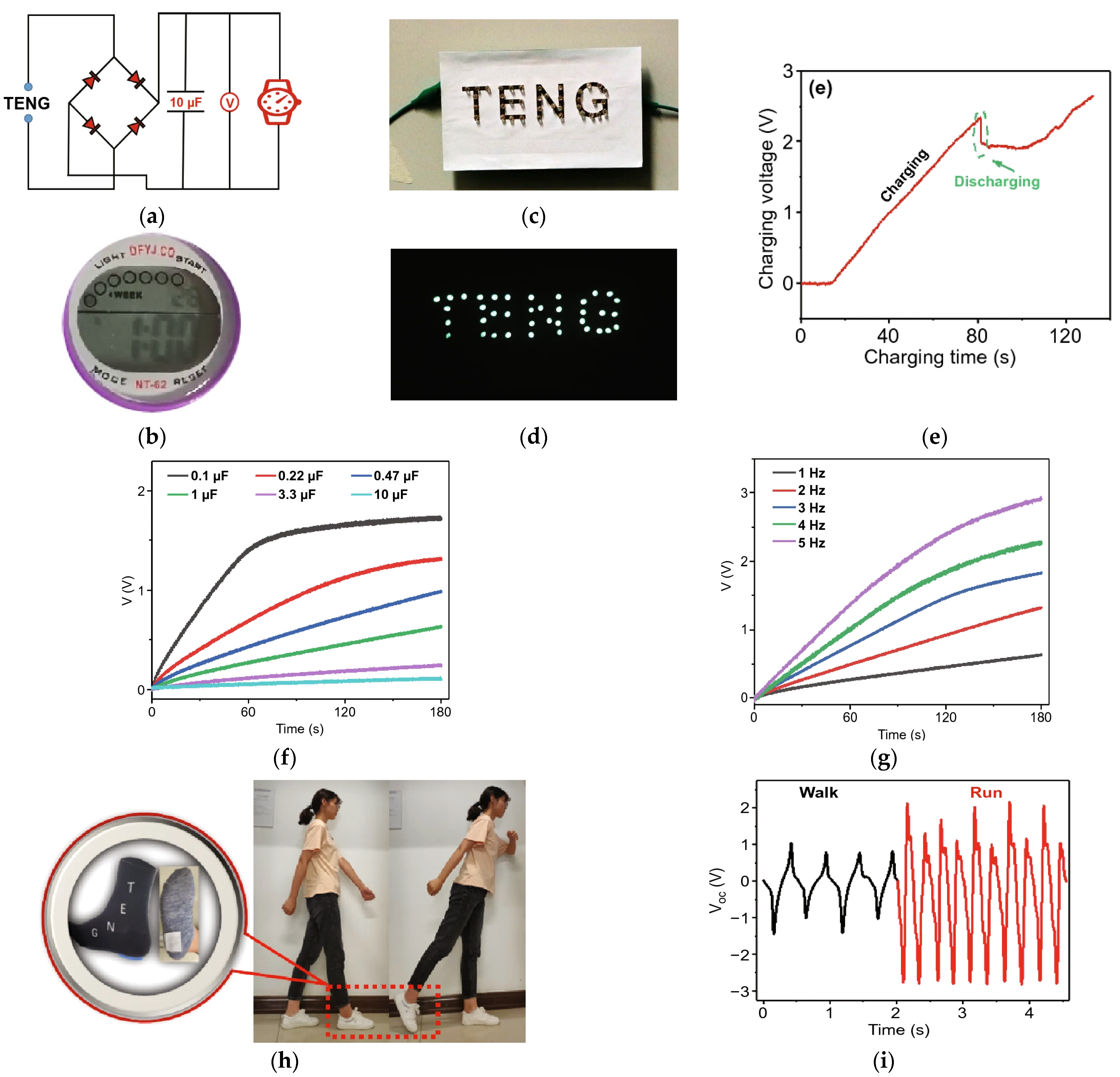
Figure 5a shows the circuit layout of the charging system using the developed F-TENG to charge a commercial watch (Figure 5b); Figure 5c,d demonstrate how to light up several LED modules with just one F-TENG. Instead, Figure 5e shows the time trend of the F-TENG charging voltage, as well as the F-TENG charging capability under storage capacitance from 1 µF to 10 µF (Figure 5f,g). Finally, Figure 5h depicts a stepper technology implemented by integrating the F-TENG into a sock; Figure 5i reports the voltage signal output in the walking and running mode.
Additionally, natural fibers and textiles can be employed to realize triboelectric harvesters. In [79], the authors described a simple way for fabricating efficient natural textile-based triboelectric nanogenerators (N-TENGs). The TENG was built in a face-to-face arrangement. Fluoroalkylated siloxane grafted fabric (F-fabric) and cyanoalkylated siloxane grafted fabric (CN-fabric) were used to create the negative and positive layers. Each triboelectric layer was fastened to a copper (Cu) cloth electrode using conductive adhesive. Finally, copper tape was used to secure the electrode to the measurement wires. The triboelectric layers of F and CN fabrics were used to create the N-TENGs in a face-to-face configuration. The negative triboelectric layer is provided by the F-fabric, while the equivalent positive triboelectric layer is provided by the CN-fabric.
Additionally, the combination of F-cot and CN-silk produced the greatest electrical output, measuring 216.8 V and 50.3 µA. (0.87 A cm−2). This study recommends using the N-TENG as a self-powering source in tiny circuits. Previous textile-based TENGs generate energy by vertically compressing and scraping objects. On the other hand, a corrugated textile-based triboelectric generator (CT-TEG) that may generate energy by stretching is presented in [80]. The CT-TEG comprises two layers: Si-rubber on the bottom and woven conductive textile on top of a silk layer. The corrugated structure on the top layer is sewn to the bottom layer. The CT-TEG may be extended to a maximum of 120 percent. With stretching and releasing actions, the CT-TEG’s maximum output performances may reach 28.13 V and 2.71 A. Furthermore, the tests show the production of enough energy from distinct human body functions to power approximately 54 LEDs.
Finally, in [81], the authors introduced a new fabric-based TENG that operates in freestanding triboelectric-layer mode. This woven-TENG includes woven electrodes and woven strips of positive and negative triboelectric material, constituting a checkerboard pattern over the electrodes with matching periodicity. The performance of the woven-TENG is greatly enhanced by using positive and negative triboelectric materials. The resulting woven TENG can produce 62.9 V open-circuit voltage, 1.77 µA short-circuit current, and 34.8 µW power under a 2 Hz mechanical oscillator and with a 50 MΩ load. For the practical application of woven-TENG in wearable devices, durability and washability were verified. After 40,000 working cycles, the VOC marginally decreases from 102 V to 85 V while the ISC decreases by 12.5%. A minor amount of material transfer, abrasion of the Ag electrodes, and fraying of the nylon fabric was seen after 40,000 operation cycles. Both outputs are steady, indicating that the woven-TENG can withstand this washing regimen. The woven-TENG’s output is also discovered to depend on the temperature and humidity levels outside for wearable devices.
The most powerful and natural action in daily human activity is said to be walking. The bi-directional gearbox-equipped exo-shoe TENG (ES-TENG), which offers enhanced and long-term output performance during regular walking, was described in [82]. The two-way gearbox efficiently transforms the whole stroke’s low frequency (1 Hz) into a unidirectional high-speed rotation (700 rpm), increasing output performance by a factor of more than 10. The rotating TENG comprises a stator, a flywheel, and a rotator with flexible blades. The dielectric blades connecting the stators and rotators are made of fluorinated ethylene propylene (FEP) and aluminum, both of which have strong triboelectric characteristics. The rotator is connected to the FEP film’s edge, and the deflected film alternately makes contact with electrodes I and II. The ES-TENG, which contains a power transmission module and a rotating TENG section, is mounted outside the shoe to recover wasted biomechanical energy from the ordinary human walking action. Moreover, employing a voltage multiplier circuit to create a boosted open-circuit voltage of more than 3 kV shows how the ES-TENG may be used for electro-stimulation applications. With much better output performance under natural walking motions, the ES-TENG makes biomechanical energy harvesting possible for various applications. Numerous moving parts that move at high speed and are subject to relatively high loads expose the device to rapid wear or failure.
Certain electrical gadgets can operate without an external power source thanks to the biomechanical energy that the stepping movement provides. For instance, the ES-TENG can charge the batteries within a commercial smartwatch using the reliable output provided by the AC/DC converting circuit [82].

3.3. Thermoelectric (TEG) Wearable-Based Energy Harvesters

TEG, a thermoelectric generator, is a device that generates energy by exploiting the Seeback effect. As represented in Figure 6, TEG is based on semiconductor bands, P-N junctions (Figure 6a), which generate a potential difference, then convert into electrical energy. However, several efforts have been made to obtain flexible TEGs, more suitable for wearable applications since they can be adapted to the human body (Figure 6b) [83]. Due to the practical restrictions imposed by wearability requirements, achieving an efficiency of 1% is also difficult [84]. It is more practicable to use a TEG on a limited body portion to optimize effectiveness and reduce wearable system power requirements. A precise design of the TEG at the material, device, and system levels is also required to optimize the amount of energy captured. Any imperfection at these levels has the potential to reduce the output power. Furthermore, when building the system, it is crucial to consider the TEG-body attachment, ease, weight, and dependability.
The materials science community is currently very interested in creating flexible electronics based on conducting polymers [85]. In general, polymer materials have several appealing qualities, such as being simple to produce, flexible, lightweight, and most importantly for thermoelectric applications-having low heat conductivity by nature. A flexible device has the benefit of conforming to the contour of the human body, which can increase the contact area and hence minimize the parasitic resistances in thermoelectric applications. Numerous doped conjugated polymer systems have been investigated as thermoelectric materials. They may be transformed into textiles using various techniques, such as coating onto pre-made fabric or spinning into mixed or mono-component fibers. A study presented a flexible thermoelectric generator characterized by a lower thermal conductivity due to its composition (Figure 7a,d) [83]; it uses a stretchy polymer made of silica aerogel and PDMS, which exploits the insulating capabilities of the material. Although a rigid material, this last produces a conglomerate that is easily castable. Figure 7b shows the employed system to measure the aerogel-PDMS conductivity; it comprises water-cooling feedthrough, heaters, a measurement channel, a support channel, thermo-couples, a sample, a vacuum chamber, and a z-stage. Figure 7c shows the composite’s thermal conductivity when the aerogel particle size is 100–700µm and 2–40µm, respectively. The simulations suggest that increasing the fill factor reduces the surfaces for collecting heat, obtaining a higher thermal resistance between the TEG and the body and environment. Less heat loss through the elastomer causes this effect to be more pronounced at lower filler thermal conductivities.
The described devices were made using n-type Bi2Se0.3Te2.7 legs and p-type Bi0.5Sb1.5Te3 legs characterized by a Seeback coefficient of ~220 µV/K and a thermal conductivity value around 1.45 W/(m K).
Figure 8a depicts the steps involved in creating flexible TEGs: first, the thermoelectric legs are deposited on the glass substrate, along with double-sided tape to prevent them from shifting (i); then, to ensure that the uncured compound solely fills the region between the legs, an aerogel-silicone mixture is shed between the legs and compressed with a second glass (ii); finally, cross-sectional microscopy was used to see how the thermoelectric legs are distributed. Using a particular stencil to spray coating the EGaIn, they generated the EGaIn interconnections (iii); then, a thin PDMS encapsulation layer was deposited to cover the realized interconnections, followed by a thick silicone layer (iv–vi). Thanks to this final encapsulation, the device works better as a heat spreader across the device. Figure 8b,c show the EGaIn interconnects, and a TEG’s cross-sectional view after the legs have been removed, respectively [83].
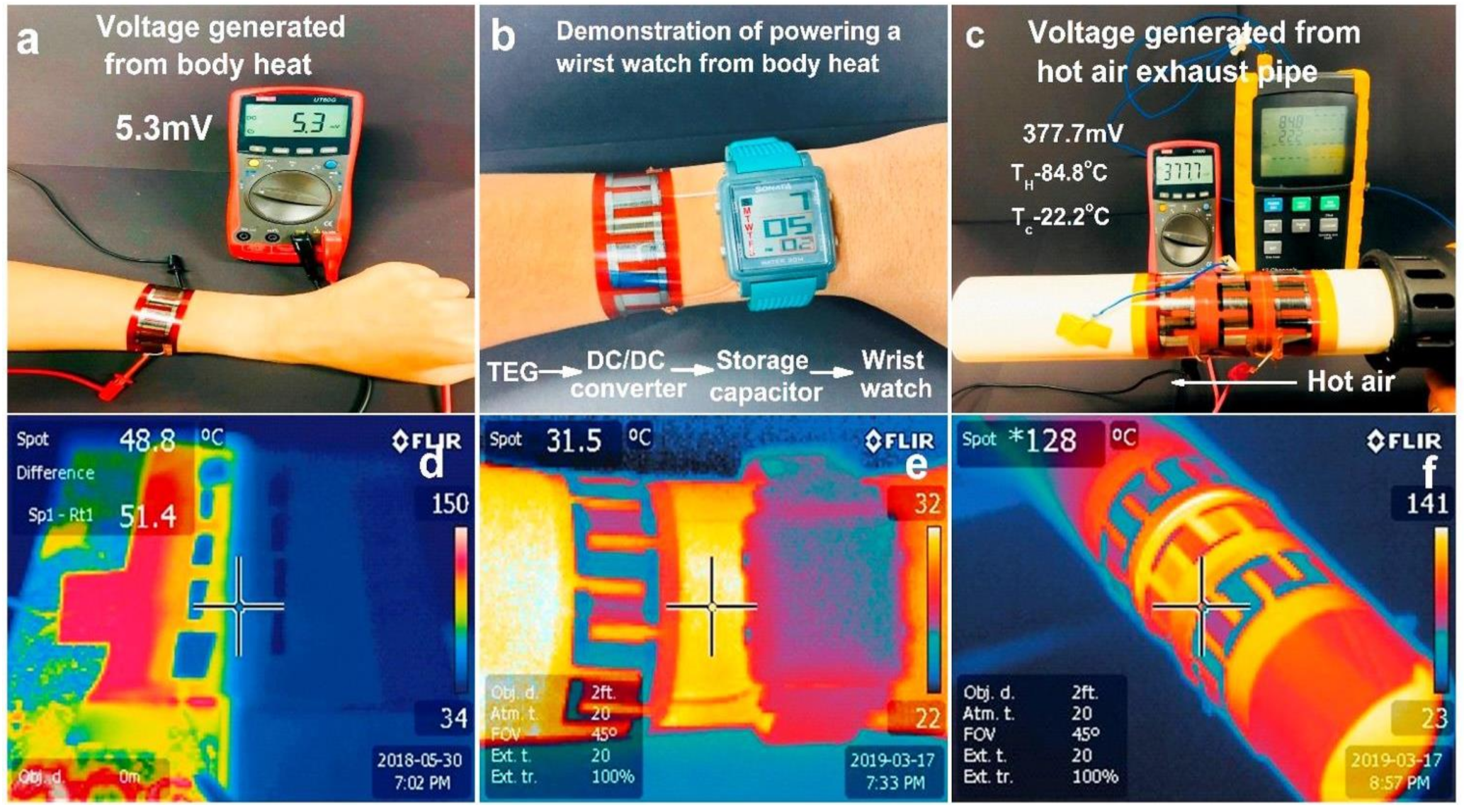
A different approach to this technology is presented in [86], which introduces a metal telluride-based TEG that, at its maximum operating temperature of 120 °C, generates a 34.7 mA cm−2 current and 8.4 mW cm−2 power density. In this study, a copper-connected p-SnTe layer and an unconnected n-PbTe layer were sandwiched to produce a TEG to sense body temperature. The resulting device features strong electrical and ultra-low thermal conductivities, contributing to a high merit figure. Sensing the change in voltage and current can detect the touch of a finger thanks to this configuration. Figure 9 show the results of some experimental tests; Figure 9a shows the voltage generated from body heat so that, as shown in Figure 9b, the recharging of a watch is possible. Figure 9c represents the voltage generated from the hot air exhaust pipe, and the infrared images of TEG for different heating emitters are shown in Figure 9d–f. Furthermore, the TEG was tested singularly under various temperature gradients (Figure 9g), serially connected, and exposed to a 120 °C temperature gradient (Figure 9h). By subjecting the device to over 400 bending cycles, its internal resistance drastically increases with the number of bending cycles, making it difficult to design the next energy harvesting section.
However, optimizing the design of the presented flexible TEG makes it possible to improve their electrical and thermal properties, allowing their operation under lower temperature gradients (ΔT) [86].
Current wearable f-TEGs are not directly compatible with garments and cannot be bent or stretched without compromising the device’s integrity or thermoelectric performance [87,88]. In [88], the authors introduce ultra-flexible textile thermoelectric generators (uf-TEGs), which include elastic fabric substrates and conductive cloth electrodes. These lasts are fabricated and assembled using a semi-automated method, including pick-and-place assembly, depositing rigid TE cuboids (n-type: Bi2Te2.7Se0.3 and p-type: Bi0.5Sb1.5Te3) and conductive textile-based electrodes over an elastic fabric substrate. The p-type and n-type cuboids are initially put up in the spaces between the TE cuboids on a temporary hard substrate. Then, elastic fabric with holes created by a laser is placed on top of the rigid substrate, and cuboids are forced into the fabric holes. On a polyethylene terephthalate (PET) mask with a design, the cuboids were scraped with solder paste. Then, using a PET thermal-released layer, the serpentine-structured electrodes are deposited on the array of the TE cuboids after being laser-cut into the conductive fabric tape. To align the TE cuboids with the serpentine electrodes, the elastic fabric and thermal released film are aligned throughout this procedure. The bottom electrodes were assembled identically after the elastic fabric, cuboids, thermal-released film, and conductive cloth electrodes were removed from the provisional support. The PET thermal-released films were then automatically reduced and separated from the electrode arrays after being heated with a heat gun set to 120 °C.
Figure 10a shows the characterization of three uf-TEGs with a different number of n-p couples, viz 8, 16, and 48 pairs, respectively. Instead, Figure 10b displays the output voltage (VL) with load resistance (RL) varying from 10 to 70, together with the open-circuit voltage (VOC) of uf-TEG with 48 n-p pairs. The VOC achieved a higher voltage (111.49 mV) than similar flexible TEG devices described in the literature at a temperature differential (T) of 33.24 K. (Figure 10e). Figure 10c,d represent voltage-current and power-current correlations graphs for 10.40, 19.83, 26.24, and 33.24 K temperature differences, along with related fitting curves. The uf-TEG generated a 64.10 W maximum power when the temperature differential reached 33.24 K, which was exceptional compared to previously reported fabric-based TEGs (Figure 10f) [88]. The 48-pair uf-TEG was up on a hot plate to test the device’s long-term stability before being cooled using an electric fan. Figure 10g showed the results of ten iterations of heating and cooling, displaying good stability with a maximum VOC change of 4.09 percent at 33.24 K. In addition, a 12-h curing cycle in a 70 °C oven was used to evaluate the 16-pair uf-TEG resistance after immersing it in water for 30 min (Figure 10h). When the sample was dried, the uf-TEG resistance dropped from 14.6 to 14.3. The VOC-ΔT curves were also measured before and after the immersion test. Figure 10i shows the uf-TE TEG’s performance before and after the immersion test and the possible usage in cloth-assembled electronic skin applications. The resistance fluctuations were minimal when the uf-TEG was bent on acrylic molds with bending radii ranging from 2.5 to 5.0 cm, with 0.5 cm gaps between them in both the x and y directions. At their maximum bending degree, they rose by 5.55% and 2.82%, respectively (bending radius of 2.5 cm).
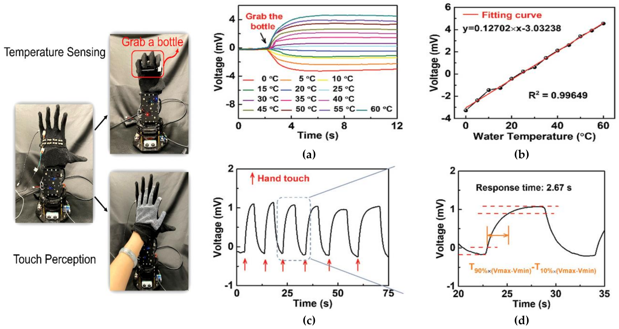
The thermoelectric capability of the uf-TEG allows its application for temperature sensing and tactile perception. The 8-pair uf-TEG, for instance, was attached to a glove and placed on a robotic hand, as shown in Figure 11. The output voltage (VOUT) increased (25 °C < TWATER > 60 °C) or decreased (0 °C < TWATER > 20 °C) when the uf-TEG got in touch with the bottle (Figure 11a). After the stabilization of VOUT, the linear relationship between VOUT and TWATER was gathered (Figure 11b). After two days of aging, the thermoelectric characteristics of both p- and n-type composite fibers remained constant. Although the long-term stability was not examined, passivation techniques may be used to preserve the stability in the air.
As previously mentioned, the uf-TEG may be employed for touch sensing. The robot hand outfitted with the uf-TEG can identify the touch of a user’s hand with a quick reaction time of around 2.67 s, as illustrated in Figure 11c,d, considerably imitating the biological function of human skin. To track health or mobility, uf-TEGs may be included in common clothes such as fabric, gloves, and wristbands rather than being utilized as an e-skin [88].
A wearable medical sensor system intended to be used in long-term healthcare applications was presented in [89]. In real-time, the device monitors the human body’s temperature, heartbeat, SpO2, and acceleration. The device combines a temperature sensor, a PPG sensor, an inertial sensor, a microcontroller section, and a BLE module. Batteries are required to power this sensor system; however, batteries have a finite lifespan, as discussed in the first section. As a result, a hybrid photovoltaic–thermoelectric energy harvesting section was integrated to feed a wearable health monitoring device. The proposed multi-source energy harvesting section includes a flexible solar panel, a TEG, a step-up converter, and two supercapacitors (50 F total capacitance). Figure 12 depicts the device architecture, which contains a flexible photovoltaic panel to scavenge energy from solar irradiance, and a TEG module to harvest energy from the body heat as well as monitor its temperature. The flexible PV panel and TEG module are hooked in series to efficiently harvest energy from the sun and body heat.
The sensor system’s firmware flowchart consists of two phases: wake-up and sleep. Firstly, the device is brought into a wake-up state; then, the microcontroller unit acquires the data from sensors and transmits them to the custom mobile app using a BLE transceiver. Afterward, the device goes into a sleep state for 1190 s, reducing its power consumption before waking up for 10 s, starting the acquisition cycle again. The test results demonstrated that the harvesting section produces sufficient energy to extend the device’s lifetime by more than 46 h, providing 2.13 mW overall power [89].

3.4. Solar Fabrics for Wearable Applications

A useful energy source naturally available is certainly sunlight, which can be scavenged by photovoltaic cells. Due to their excellent mechanical stability/robustness (i.e., bending and compression), high power-to-weight ratios, and affordable manufacturing processes/devices, flexible-wearable solar cells provide viable alternatives to conventional electricity sources [90]. These photovoltaic devices are the portable power sources of the future that can be fitted to any substrate. More significantly, flexible solar cells may be integrated into various objects, including bags, clothes, shelters, airplanes, vehicles, and more, to provide them with excellent power-to-weight ratios at low production costs compared to other prevalent technologies. Several efforts have been made to integrate them into wearable systems, overcoming their intrinsic rigidity.
A novel technique to use the sun’s energy is through solar fabrics; these lasts are ten times lighter than framed panels, non-toxic, and can be bent or bonded to any surface. Additionally, they have a longer lifespan of up to 20 years. This innovative technology represents a good and promising alternative with respect to conventional PV panels. The high-efficiency rate of conventional cells and panels has been their main selling point, with current technologies capable of well over 20% conversion rates. S. Arumugam et al. described the novel spray-coating method to create organic solar cells on fabrics for wearable energy harvesting applications [91]. A screen-printed interface layer reduces the surface roughness of the ordinary woven 65/35 polyester cotton fabric utilized in this work to a few microns. Fabric solar cells are made by screen printing an interface layer onto fabric substrates. The screen design ensures that the interface layer is just imprinted where necessary, retaining the fabric’s elasticity and maximizing breathability compared to typical pre-coated textiles. In a standard thermal oven, the interface layer can withstand processing temperatures of 150 °C for up to 45 min without degrading and has surface-free energy of 35 mN/m. It also has a good thermal resistance. The experimental results indicated that the spray-coated PV fabric obtained PCE (0.01%), similar to traditional glass-based panels. Decreasing the thickness of the ZnO-NP layer enhances device performance, while compressing the bottom AgNW layer during the annealing step prevents short circuits and decreases resistance. An all-solid tuneable energy cloth with concurrent solar energy scavenging and storage capability was developed in [92]. The solar energy harvesting module is an all-solid dye-sensitized solar cell textile (i.e., ZnO-based DSSC). In contrast, the energy storage module is a customizable fiber supercapacitor (TiN-based) with rapid charging abilities and ultrahigh bending resistance. Self-harvesting solar energy can charge the textile sample to 1.2 V in 17 s and discharge it at a 0.1 mA discharge current density in 78 s. This technology enables customization of the multifunctional material into the desired shape without affecting its functionality, leading to stylish smart garments for wearable self-powering systems with enhanced user experience and increased flexibility for fashion design.
In addition, one trouble that researchers are trying to resolve is the permeability of the encapsulation barrier used to protect solar cells from environmental agents such as humidity, water, dust, etc. The study reported in [93] suggests the introduction of a capping layer of SiO2-polymer compound that allows the generation of a nano-stratified encapsulation barrier to obtain a washable device. Thanks to its chemical stability, the encapsulation’s water vapor transmission rate (WVTR) is also guaranteed under aqueous environments; in fact, the polymer solar cell (PSC) percentual of degradation after washing 20 times was just 2%. PSC fabrication is based on a barrier-coated textile substrate that has the following structure:
  • Textile support material;
  • Bottom encapsulation layer;
  • Ag cathode (100 nm);
  • PFN-Poly-Fluorene electron transporting layer (8–10 nm);
  • PTB7-Th-PolyBisThiophenBenzoDitiophene-Thieno: PC71BM active layer (100–110 nm);
  • MoO3 hole transporting layer (10 nm);
  • Ag anode (10 nm);
  • MoO3 optical protective layer (30 nm).
The acrylic adhesive attaches the encapsulation barrier to the device so that the attachable encapsulation protects the optoelectronic modules made on the textile substrate; then, the conductive paste is used to connect the thermally deposited metal electrodes with the conductive fiber.
There are two different ways of applying the encapsulation barrier; direct encapsulation prevents the infiltration of oxygen and moisture, exposing the device to thermal and ultraviolet damage. These troubles do not happen with the attachable encapsulation, even if it is sensible to the penetration of moister and oxygen that can be overcome with new adhesive materials. The attachable encapsulation method allows the application of the protective layer over wide flexible photovoltaic panels without following process steps. Tests conducted in [93] show the effectiveness and reliability of the developed capping layer; the Rate of Change (ROT) of the main characteristic parameters of the encapsulated solar cell is almost constant over several washing cycles.
This study shows that the addition of SiO2-polymer composite goes against the phase transition of Al2O3 (during the washing process) and, thus, its decisive role in the next generation of integrated harvesters for wearable E-textiles [93].
Solar cells are also engaged in charging devices for a limited time; in [94], the authors presented a solar harvesting cloth comprising 200 tiny solar cells able to charge a 110 mF textile supercapacitor in 37 s. Individually housed in translucent resin micro-pods, the tiny solar cells are coated with a flexible textile sheath made of packing fibers and a tubular knitted structure. The fibrous sheath’s ability to take on any hue, depending on the desired color of the solar-E-yarn and subsequent fabrics, gives it a significant advantage over other solar E-textiles that have been suggested. The performance of the solar-E yarns and the resultant textiles might be further enhanced if the photoactive side of the yarns was soaked with transparent resin.
Figure 13a shows solar-E yarns created from 10 separately soldered and encased solar cells. Figure 13b depicts a solar energy-harvesting cloth made with 200 solar cells. Then, a comparison between the developed solar energy-harvesting fabrics (Figure 13c, each equipped with 50 solar cells) with a commercial one was carried out.
The testing findings revealed that the commercially available flexible solar panel had a power density comparable to that of white solar energy harvesting fabric after vertically arranging solar textiles onto a t-shirt. The studies revealed that the resin used in the solar-E-yarns enhanced the power densities for the white solar energy collecting fabric by 35.3% but only by 24.3% for the flexible solar panel. This result demonstrated that solar energy-capturing textiles were acceptable for producing electricity when exposed to natural sunlight since the black and red solar energy harvesting fabrics performed worse in terms of power densities (i.e., −54.4% and −23.5%) than the white ones (Figure 14) [94]. The exclusive stiff molecular solar thermal energy storage (MOST) or photothermal materials (PTMs) used by current solar thermal systems result in inadequate solar spectrum utilization and a lack of wearability. In [95], a team of scientists developed a visual solar storage fabric (VSSF) that combines a wearable contrast photochromic display with UV-Vis-NIR wavelengths. The Azo-PCM@PS nano-capsule and Cs0.32WO3 nanoparticle are combined in this VSSF to enable photochemistry and thermophysics related to energy storage and Vis-NIR light harvesting.
The resulting device demonstrated a high heat release (83 °C) and energy efficiency (4.8%) when exposed to sunshine. To develop wearable visual solar storage fabric (VSSF), cotton fabric is covered with Cs0.32WO3 nanoparticles and Azo-PCM@PS nanocapsules [96]. The core/shell mass ratio was tuned between 1:15 to 5:15. The gray factor between the Azo-PCM (dark color) and PS levels affects the core/shell structure of the Azo-PCM@PS nanocapsule (light color). As the Azo-PCM yolk progressively fills up the shell and the Polystyrene (PS) shell thins, the core almost completely fills the nanocapsule when the core/shell mass ratio reaches 5:15 [97].
Photo-isomerization in the Azo-PCM composite and nanocapsule regulates the energy storage and release of the Azo-PCM@PS nanocapsule [96]. According to the relationship between absorbance and the percentage of cis-to-trans conversion, blue light causes a greater photo-isomerization in the photostationary state (PSS). Due to the two-way switch caused by photos in monochromatic light, full cis-to-trans conversion is possible [98]. Although PS, the shell used in Azo-PCM@PS nanocapsules, has strong light transmission, the pace of isomerization is influenced by the thickness of the shell. The photoisomerization kinetics are monitored to determine the isomerization speed, supposing a first-order kinetics process takes place [26,28]. The isomerization rate of azo-PCM rises with thinner shells due to lower light transmission losses in propagation at the same core mass with varying core/shell mass ratios.
As examined in [99], the light intensity and incident light angle are crucial factors for the correct operation of solar panels, which must be considered when designing wearable devices. Textiles made with solar cell-enhanced yarns can resist household washing and maintain 90% of their initial power production after 15 machine wash cycles, according to tests conducted for this study. The three-step procedure of soldering, encapsulating, and covering fibers results in solar-E-yarns.
The linear relationship between light intensity and ISC explains its significant changes during the yarn production process. On the other hand, VOC changed just slightly due to its logarithmic dependence on light intensity [100,101]. As a result, ISC may be considered a parameter representing the quantity of light flux received by the embedded SC. Because of the micro pods’ convergent (lensing) and light trapping effects, the ISC and PMAX values increased by 18.3% and 21.7%, respectively, when the SCs were encased within the resin micro-pods. An earlier study [102] explored the performance of photodiodes implanted within thin resin micro pods. The influence of the micro pods’ size, shape, and optical characteristics, as well as the device’s location within the micro pod, were approximated using a theoretical model and physically tested. In this study, the design constraints decided upon the micro pod geometry, size, and SC location to optimize the desirable qualities of the resulting textiles, such as thickness and drapability. The SC within the solar-E-yarn got less light as a result of the fibrous covering. Incident light can pass through the fibrous sheath and into the micro pod in one of two ways: either the fibrous sheath’s porous surroundings would allow for direct passage of some incident light through the structure without interference, or the light might diffuse through the sheath after interference. Light absorption can be further reduced by employing textile fibers with less shine [103]; on the other hand, scattering can be reduced by using fewer, thicker, or fibers with a lower refraction index fluorinated polyesters or silicones). However, these changes impact the materials’ look, feel, and capacity to trap light.
Three distinct types of electrical device charging capacity of the SC embedded fabric were examined [99]. The gadget demonstrated its ability to charge various storage devices, as well as feed a mobile phone, a fitness tracker, and LEDs woven into the fabric (supercapacitors, Li-ion, and LiPo batteries). By weaving PV material coated wires or flexible PV tapes into textiles [104,105], this novel way of adding solar energy harvesting capabilities outperforms conventional techniques such as laminating, printing, or coating PV onto fabric surfaces in terms of aesthetics, texture, draping, and washability. This ideal textile behavior is provided by the SC embedded yarn’s unique architecture, created by employing electronic yarn technology.

3.5. Hybrid Textile-Based Energy Harvesting Solutions

Hybrid energy harvesting devices have been suggested recently to address the single energy harvester’s energy-sufficiency problem [106]. In addition to collecting energy from various sources, hybrid harvesting also involves transforming energy into electricity via various transduction methods. A proper hybridization of various energy conversion technologies may greatly increase power production and space utilization efficiency.
Due to its small vertical displacement and ease of integration, hybrid generators combining piezoelectric and triboelectric harvesting sections offer advantages when working in contact mode for applications involving wide-area floor coverings such as runways and carpets [107,108,109]. However, these solutions can be applied to wearable devices, enabling the implementation of self-powered smart garments [110]. In [111], Zhang et al. introduce a revolutionary wearable solar energy-driven pyrothermoelectric hybrid generator by combining a high-efficiency solar absorber, a pyroelectric film, and thermoelectric yarns (PTEG). When exposed to sunlight, the solar absorber transforms solar energy to heat energy. While temperatures at the outermost area of the PEDOT: PSS yarns beneath the thermal shielding remain relatively low, temperatures at the PVDF layer and the middle region of the PEDOT: PSS (poly-(styrenesulfonate)) yarns can be greatly raised. An annular ΔT forms because of heat flow conducting from the PTEG’s core outward in this case. PTEG can efficiently capture both dynamic temperature changes and static temperature gradients. The PTEG efficiently charges two commercial capacitors to a cumulative voltage of 3.7 V in under 800 s under a lighting intensity of 1500 W/m2 (1.5 suns). The total energy can illuminate 73 LED light bulbs.
Hybrid textiles for scavenging both luminous and mechanical energy were also reported in the literature; for example, a textile-based energy harvesting device is presented in [112], which combines a triboelectric fabric with a fiber-shaped dye-sensitized solar cell. The resulting hybrid power-textile is soft, flexible, wearable, and has great potential for use in smart textiles or wearable electronics. The textile consists of Ni threads coated with a parylene layer, providing triboelectric functionality. Furthermore, the textile integrates a fiber-shaped dye-sensitized solar cell (FDSSC) constituted by Ti wire support wrapped in a Pt wire, acting as a cathode, immersed by a TiO2 layer. The characterization results indicated that the TENG fabric could achieve 1.9 W m−2 maximum output power density, whereas the FDSSC-based textiles reached 7% PCE.
The development of wearable technology has recently sparked a lot of interest in hybrid piezoelectric and triboelectric nanogenerators. For instance, the PDMS/graphite composite triboelectric layer, the P(VDFTrFE)/Ag piezoelectric layer, and three fabric electrodes in a cascaded configuration were employed to build the hybrid generators [113]. Ag nanowires were employed in the piezoelectric layer to increase the piezoelectricity and electric conductivity of P(VDF-TrFE) nanofibers and obtain a high dielectric constant and low dielectric loss. Graphite nanoparticles were employed to improve the dielectric constant of the triboelectric layer. Individual unit output voltage and current, as well as a hybrid generator, were all detected. Two AC/DC converters were employed to avoid output degradation caused by phase mismatch between the output signals from the two units. The results indicated that the hybrid generator’s output power matched the combined output of the two separate units. Besides, in [114], the authors deploy an elastic, porous, and robust nanofiber composite (LPPS-NFC) (SEBS) for piezoelectric and triboelectric energy harvesting; it was manufactured by the electrospinning technique of lead-free perovskite/poly(vinylidene fluoride-co-hexafluoropropylene) (PVDF-HFP) and styrene-ethylene-butylene-styrene. The efficient electron transfer and reduced charge loss caused by the good energy level matching between Cs3Bi2Br9 and PVDF-HFP improve the electron-trapping process.
Consequently, the presented LPPS-NFC-based energy harvester surpasses the output voltage record for halide-perovskite-based nanogenerators with an outstanding electrical output (400 V, 1.63 A cm2, and 2.34 W m2). The LPPS-NFC also provides exceptional elastic properties, waterproofness, and breathability, enabling the creation of strong wearable devices that transform mechanical energy from various biomechanical motions into electrical energy to power conventional electronic devices. For instance, a self-sustainable pulse sensor combining piezoelectric and triboelectric effects is reported in [115]; this last consists of PDMS-Ecoflex self-arched layer and Al flat layer properly coupled, representing the triboelectric section (Figure 15a). Besides, the device comprises a metalized PVDF layer, representing the piezoelectric section. The test results indicated that the device has a short-circuit current and open-circuit voltage of 500 nA and 5.2 V, respectively.
Furthermore, a flexible and stretchable PZT-based piezoelectric nanogenerator was presented in [116]; the device carries out three sequential energy conversion phases to scavenge ambient energy as much as possible (Figure 15b). This process includes two triboelectrification processes and one piezoelectric electrification process, reaching a 600 V open-circuit voltage and 1.11 W m−2 power density, respectively. In addition, (PEDOT: PSS)-coated fabric and PZT micro-transducers were combined to obtain a self-powered and self-functional sock [117] (Figure 15c). The characterization demonstrated that the triboelectric and piezoelectric contributions could reach 11µW/cm2 and 128 11µW/cm2 power densities, respectively. Finally, in [118], the authors introduced triboelectric and pyroelectric–piezoelectric nanogenerators (PPENGs) based on PVDF film and fluorinated ethylene propylene (FEP)-Cu triboelectric layers. The TENG appears to perform the main role because the output power of the PPENG and TENG can reach up to around 184.32 µW and 4.74 mW.

4. Comparison between Energy Harvesting Technologies Previously Discussed

This section aims to find a better alternative to the research work previously treated; it is divided into sub-sections, so piezoelectric, thermoelectric (TEG), triboelectric and solar fabrics, to compare each technology itself.

4.1. Piezoelectric Wearable-Based Energy Harvesters: Comparative Analysis

This subsection compares the piezoelectric energy harvesting solutions for wearable applications discussed in Section 3, as shown in Table 3, according to the used material, performance, and suitability to be integrated into wearable applications. In detail, the power density was employed to express the ability of the piezoelectric transducer to generate power per unit area. In addition, the sensitivity was reported for devices that could be employed for sensing applications, representing the device’s capability to respond to input quantity.
In [58], a lightweight and flexible nanogenerator was created using an electrospinning process to create a self-powered temperature sensor. The effect of LiCl on piezoelectric response can be a low-cost and simple way to increase the output voltage of a device. Wearable electronic systems, safety monitoring, smart sensors [119], and medical diagnostics are likely to benefit from the nanogenerators developed.
The hot pressing process presented in [61] allowed the article to provide a low-cost, mass-production friendly, and highly integrated fabric; tests showed an output voltage of up to 5.3 V, making it ideal for integrated wearable electronics. The final product discussed in [62] exhibits good output voltage performance and long-term stability; this study offers a convenient and creative method for self-powered wearable pressure sensors for disease rehabilitation and vital sign monitoring. In [63], an MFP textile for surface-modifying PDA physiological monitoring was designed. The phase-field modeling and experiments demonstrate that adding PDA to electrospun BTO/PVDF nanofibers substantially increases interfacial adhesion and linkage, leading to better mechanical and piezoelectric performance of the nanocomposites as made. This work adopts a unique methodology to maximize piezoelectric energy harvesters and active sensors for wearable healthcare monitoring.
Finally, the second presented technology is the most interesting for its easy integration into clothes and excellent performance, making its introduction into the market possible [9].

4.2. Triboelectric Generators for Wearable Applications: Comparative Analysis

This sub-section compares triboelectric energy harvesting solutions for wearable applications discussed in Section 3, as shown in Table 4, from the point of view of the triboelectric material, performances (open-circuit voltage and power density), and suitability for wearable applications.
Current research focuses on increasing the output of T-TENGs because they generally have a lower output than stiff or conventional thin film TENGs [71]. Even though the T-TENG microsystem is still in its infancy and confronts formidable obstacles, it has already shown remarkable promise and promising future applications in wearable electronics, biomedicine, and the IoT, which call for additional research.
To capture mechanical energy and act as a multipurpose sensor for tracking human mobility and health, a 3D double-faced interlock fabric triboelectric nanogenerator (3DFIF-TENG) is designed and constructed [75]. This wearable TENG may be utilized as a self-powered multifunctional sensor because of its distinctive structure, which enables it to create energy by bending and stretching itself without using additional triboelectric materials. Based on the output data, the 3DFIF-TENG can be utilized as a bending sensor, a hand pressure sensor, or a weighing cushion sensor.
The F-TENG developed in [77] has great characteristics, as can be seen, if applied to a self-powered wearable keyboard (SPWK). It implements a biological recognition function, finding use in human-machine interaction devices. It is featured by excellent fit, self-security, and self-feeding qualities, as well as by low cost, high precision, and contact electrification performance. According to [82], the ES-TENG is a new shoe-attachable TENG for reliably transforming walking motion into energy. The stepping motion’s biomechanical energy may provide enough DC voltage to power a range of electronic devices, enabling the use of such devices in real time without the need for an external power source. Using the consistent output from the rectifier, it is also feasible to charge the batteries of low-power electronic devices. A very high voltage output of up to 3 kV is made possible using a voltage-multiplier circuit. The movement naturalness that the ES-TENG needs to generate electricity makes it preferable over the other triboelectric technologies, also considering its output performance in terms of output voltage [82].

4.3. Thermoelectric Wearable-Based Energy Harvesters: Comparative Analysis

This subsection compares the thermoelectric energy harvesting solutions for wearable applications discussed in Section 3, as shown in Table 5, from the point of view of the support material, performances such as open-circuit voltage (VOC), Seeback coefficient, and power density, as well as the suitability for wearable applications.
F-TEGs with eutectic gallium indium (EGaIn) liquid metal connections are detailed in [83]. These TEGs are covered in a new high thermal conductivity polymer to realize interconnections between the thermoelectric legs reaching maximum stretchability and low electrical resistance. A thin Cu layer acting as a heat spreader improves the device’s performance, increasing the output power. This feature enables their application in self-powered wearable applications, allowing scavenging energy from body heat.
The final product in [86] is an in-plane flexible p-SnTe/n-PbTe metal telluride-based device with a rough surface that improves electrical properties; it is a good industrial waste heat recovery device. Compared to other fabric-based TEGs, the uf-TEGs [88] demonstrated unprecedented output voltage and power. In addition, the resulting devices demonstrated good flexibility, as they can be stretched, bent, or folded to suit the surface.
The paper [90] describes a photovoltaic-thermoelectric hybrid energy harvester that can be used to power a self-powered medical sensor system. The proposed hybrid energy harvester is used to extend the sensor system’s lifetime by more than 46 h, allowing a total power consumption of 2.13 mW. Finally, the developed Android application continuously monitors the system’s sensor data. The sensor system provides a portable solution for monitoring human body temperature, heartbeat, SpO2, and acceleration over time. Considering the extreme flexibility and charging capacity in output power, the technology presented in [86] seems to be the most easily adaptable option to different devices [120].

4.4. Solar Fabric for Wearable Applications: Comparative Analysis

This subsection discusses the energy harvesting solutions with solar fabrics for wearable applications discussed in Section 3, as shown in Table 6, from the point of view of the support material, its performances (open-circuit voltage, power density, and conversion efficiency), and its suitability for wearable applications.
The added functionalized SiO2-polymer composite capping layer in [94] adds stability by chemically reacting with the interior Al2O3 layer to avoid damage to the porous membrane during washing. The PSCs created on a genuine textile substrate showed exceptional durability even after washing without sacrificing the mechanical flexibility of the cloth. The next generation of power sources for wearable E-textiles is anticipated to rely heavily on textile-based washable PSCs [121].
The white solar energy collecting fabric exhibits performance equivalent to a commercially available flexible solar panel, demonstrating similar power density, according to the experiments presented in [95]. The improvement in power density brought about by resin impregnating the top fibers of the solar-E-yarns demonstrated power densities that were 24.3% higher for the flexible solar panel and 35.3% higher than for the white solar energy harvesting fabric. The study’s findings demonstrate that solar energy collecting materials are appropriate for producing electricity when exposed to natural sunlight.
VSSF has been tried with entire sun spectrum utilization by creating the wearable fabric [97]. Used in conjunction with photothermal materials (PTMs) and STFs, it may improve solar efficiency to 4.8% above that of individual PTMs and STFs systems. The development of wearable solar energy management is facilitated by creating a sunlight-stimulated self-heating (SH) wrister for cold injury prevention. The wearable VSSF can potentially be employed for efficient energy management outside.
The approach presented in [99], incorporating photovoltaic scavenging capability into textiles, outperforms current technologies such as coating PV onto fabric surfaces or weaving PV material coated wires or flexible PV tapes into fabrics. The final result, a solar energy harvesting fabric with an active area of 44.5 mm by 45.5 mm, has a 2.15 mW/cm2 output capacity sufficient to run a smartphone. The SC was included in the resin micro-pod, which boosted output power due to convergent (lensing) and light trapping effects. After wrapping with a fibrous sheath, the power production significantly decreased due to the reflection and light absorption effects. According to the durability testing, fabrics with SC-embedded yarn may maintain their performance even after 15 domestic machine wash cycles, 25 manual wash cycles, and 6000 abrasion cycles. This last material stands out from the others for its extreme resistance to both washing and abrasion cycles, making it an optimal choice for integration into clothes and, therefore, more comfortable for the end-user.

5. Comparison of Presented Review Work with Similar Ones Reported in the Literature

This section aims to highlight the strengths that differentiate this review work from others by comparing from the point of view of the covered topics and reported contents; it focuses on aspects sometimes put in the background, such as considerations of the importance of storage devices and power management in designing of wearable devices.
Unlike the paper [55], our review work presents an analysis of the currently most promising technologies for the implementation of energy-autonomous devices, deciding to leave out technologies that would not currently be able to guarantee the power supply of a wearable device, such as RF or biofluids energy harvesting. However, the third section of our review work deals separately with the available technologies, such as piezoelectric and triboelectric energy harvesters, that allow using human body movements as a free energy source. The devices suitable for wearable devices are the focus, excluding implantable solutions. While the presented analysis is based on the architecture of the energy harvesting device and its working principles, [122] also discusses the final device that needs to be powered; in fact, it treats all energy harvesters technologies reassuming them into a single section.
Instead, the article in [123] focuses on various advanced sources, not just biomechanical ones (e.g., joint movements, walking pressure, center of gravity movements, etc.). Furthermore, it focuses on technologies such as electromagnetic that are unsuitable for integration into tissue but require external application on the human body’s surface, making the device more invasive in everyday life. Moreover, the review in [113] describes the generic structure of energy harvesting fiber-type devices, not describing in detail the devices present in the literature. It treats only the fiber-based system (PENG and TENG) functioning principles and general architecture, avoiding photovoltaic and thermoelectric harvesters, similarly to the ref. [124]. Additionally, it does not provide any comparative analysis between devices using a given energy harvesting technology. The review papers [125,126,127] cover available materials and applications of piezoelectric films and nanogenerators, not dealing with the other harvesting technologies covered by the presented paper. Furthermore, the authors in [128] dealt with vibration energy harvesting transducers, including piezoelectric and electromagnetic, to convert the kinetic energy into electrical one. Our review work does not cover electromagnetic harvesting solutions since they are considered difficult to adapt to integration into a wearable device. In addition, in [129], the paper provides an overview of nanotechnology-enabled energy harvesters not necessarily applicable to wearable applications, on which instead the proposed article is focused. In addition, the review [129] superficially deals with the triboelectric nanogenerators, considered by us to be one of the most promising transduction mechanisms for the next generation of self-powered wearable devices. In conclusion, the presented review focuses on transduction mechanisms and technologies that currently can find an application for supplying self-powered wearable devices, leaving out other ones considered hardly applicable in a real scenario.
Finally, a comparative table is below reported, highlighting the main topics treated in the considered review works and the advantages of our analysis (Table 7).

6. Strengths and Limitations of the Discussed Technologies and Future Perspectives

Table 8 summarizes the strengths and limitations of each analyzed technology from operative and manufacturing points of view, as well as their application scenarios. Although piezoelectric technology is very mature, the development of wearable transducers now shows several open issues related to their actual application in a real scenario due to their stability over a long operation period and their sensitivity to temperature and moisture. In addition, the limited electromechanical coupling of the transducer with the human body limits the power extracted from joint movements, confining the use of such devices only to the power supply of low-power electronic devices. Piezoelectric transducers mounted to the arm and shoulder provide power densities of 4.92 and 14.33 mW cm3, respectively. The main open issues representing significant obstacles to the development of wearable energy harvesting sections are [130]: (1) The devices for up-converting frequency, and amplitude of human motion signal are rigid and bulky; (2) Novel piezo-materials are still far from being ready for future uses. Although certain harvesters have undergone testing on human subjects, their practicability in terms of durability, stability, and compatibility has not been shown; (3) Most piezoelectric energy harvesters can only scavenge electricity from the upper limb in the nW to µW range; lower than the power requirements of common wearable devices. Different harvester designs and piezoelectric materials can be created. Specifically, the main research topics are to improve the overall embedded system fed by the harvesting section (i.e., energy storage, conditioning section, processing unit, sensors, a communication unit, etc.), development of high-performance lead-free materials, and development of hybrid energy harvesters.
Similarly, triboelectric harvesting technology suffers from effects induced by continuous mechanical deformations on the transducers, limiting their durability and degrading their performance. Solving the abovementioned issues, piezoelectric and triboelectric technology are the most promising energy harvesting technologies. Because of their superior mechanical strength and processability, yarn and textile TENGs would have greater potential in commercialization strategies [131]. However, further work is needed to develop the circuit and internal connections to integrate other TENG suits or different energy storage systems. Wearable TENGs made of fibers, yarns, fabrics, and textiles provide novel approaches to self-charging power systems featured by high comfort and wearability. In addition, biocompatible device packaging, flexibility, and sensitivity of TENGs should be considered for applications involving implanted medical devices. Similarly, hybrid energy generators can be considered to improve the output power making them suitable to feed medium-power wearable devices [132].
The wearable TEGs are the harvesting technology with the slowest progress compared to the other ones investigated. Improving efficiency, durability, biological compatibility, and flexibility are current challenges for the actual application of flexible TEGs to wearable devices [133]. There is still much to be done in this field since the performance of current thermoelectric materials and devices remains unsatisfactory. Although non-toxic materials such as Ag2Se, MgAgSb, SnSe, and others perform well at room temperature and have a chance to replace Bi2Te3, there are still numerous obstacles to overcome, including TE characteristics, mechanical properties, cost, mass manufacturing, and dependability.
Solar textiles are the most mature technology compared to the previously discussed technologies, representing the most viable solution for implementing self-powered wearable devices and accessories [134]. However, it will be necessary to thoroughly quantify the textile properties and understand the device’s durability for using solar E-textiles in wearable systems. Further research may be required for many devices since they may not already have the requisite characteristics or robustness; nevertheless, it is impossible to make a firm judgment about this without testing data. To enable the long-term usage required of a product, many solar E-textiles will also need to increase their stability. A large-scale manufacturing procedure for these textile solar cells would also be required.

7. Conclusions

Energy harvesting technologies are the main study subject to overcome battery limitations, such as reduced lifespan and power density, especially considering the constraints required by sports and biomedical devices, imposing a trade-off on battery size, weight, capacity, and technology. Properly sized and designed energy harvesting sections enable scavenging energy from environmental and human body sources to recharge the battery extending the wearable device’s autonomy.
This article analyzes recent energy harvesting technologies and devices suitable for integration inside wearable devices; considering the application, the main features required are flexibility, stretchability, lightness, and so on. At first, the most promising energy sources exploitable for wearable applications are introduced. Then, an overview of wearable energy harvesting technologies is presented, focusing on textile-based and flexible solutions, such as piezoelectric, triboelectric, thermoelectric, and solar fabrics. However, hybrid solutions combining different harvesting methods are treated, integrating several energy contributions, and thus improving the energy extraction efficiency. Furthermore, comparative analyses of the discussed harvesting solutions for each transduction mechanism, considering the performances and applicability. Useful insights are provided for each technology, outlining the features and strengths, among those of the analyzed solutions, of the future generation of wearable energy harvesting systems. Finally, a comparison between the present review work and similar ones is presented, highlighting its main strengths.
We believe that triboelectric energy harvesting technology offers the best prospect for developing energy-autonomous wearable devices, as it is characterized by a simple fabrication that allows its implantation on large surfaces, thus guaranteeing the supply of significant output power values [71]. In addition, the layered structure of these transducers allows the simple integration of other energy harvesting technologies, such as piezoelectric, to improve the output power with further energetic contributions [113,114,116,117].

Author Contributions

Conceptualization, R.D.F. and P.V.; investigation, R.D.F., P.V. and R.P.; resources, R.D.F., C.D.-V.-S. and R.V.; data curation, P.V., R.D.F. and R.P.; writing—original draft preparation, R.D.F., R.P. and P.V.; writing—review and editing, C.D.-V.-S. and R.V.; visualization, P.V., R.D.F. and R.P.; supervision, C.D.-V.-S. and R.V. All authors have read and agreed to the published version of the manuscript.

Funding

This research received no external funding.

Institutional Review Board Statement

Not applicable.

Informed Consent Statement

Informed consent was obtained from all subjects involved in the study.

Data Availability Statement

Data of our study are available upon request.

Conflicts of Interest

The authors declare no conflict of interest.

Nomenclature

The following acronyms are used in this manuscript:
AcronymExtended meaning
A Sample area (m2)
e   Charge of electron   ( Coulomb )
ICurrent generated by triboelectric charge transfer (Ampere)
I sc Short-circuit current (Ampere)
N number of transferred electrons (Adimensional)
PMaximum power density (W/m2)
QSCShort-circuit charge transfer ( Coulomb )
RLLoad Resistance (Ω)
s Cross-sectional area (m2)
TWATERWater temperature (°C)
v Electron transport rate (m−1s−1)
V oc Open-circuit voltage (Volt)
VOUTOutput Voltage (Volt)
ΔTTemperature difference (°C)

References

  1. Holzinger, A.; Röcker, C.; Ziefle, M. Smart Health: Open Problems and Future Challenges; Springer: Berlin, Germany, 2015; ISBN 978-3-319-16226-3. [Google Scholar]
  2. Zou, Y.; Bo, L.; Li, Z. Recent Progress in Human Body Energy Harvesting for Smart Bioelectronic System. Fundam. Res. 2021, 1, 364–382. [Google Scholar] [CrossRef]
  3. Mateu, L.; Dräger, T.; Mayordomo, I.; Pollak, M. Chapter 4.1-Energy Harvesting at the Human Body. In Wearable Sensors; Sazonov, E., Neuman, M.R., Eds.; Academic Press: Oxford, UK, 2014; pp. 235–298. ISBN 978-0-12-418662-0. [Google Scholar]
  4. Nakhkash, M.R.; Gia, T.N.; Azimi, I.; Anzanpour, A.; Rahmani, A.M.; Liljeberg, P. Analysis of Performance and Energy Consumption of Wearable Devices and Mobile Gateways in IoT Applications. In Proceedings of the International Conference on Omni-Layer Intelligent Systems, Crete, Greece, 5 May 2019; Association for Computing Machinery: New York, NY, USA, 2019; pp. 68–73. [Google Scholar]
  5. Glaros, C.; Fotiadis, D.I. Wearable Devices in Healthcare. In Intelligent Paradigms for Healthcare Enterprises; Silverman, B.G., Jain, A., Ichalkaranje, A., Jain, L.C., Eds.; Studies in Fuzziness and Soft Computing; Springer: Berlin/Heidelberg, Germany, 2005; pp. 237–264. ISBN 978-3-540-32362-4. [Google Scholar]
  6. Iqbal, S.M.A.; Mahgoub, I.; Du, E.; Leavitt, M.A.; Asghar, W. Advances in Healthcare Wearable Devices. NPJ Flex. Electron. 2021, 5, 1–14. [Google Scholar] [CrossRef]
  7. Hung, K.; Zhang, Y.T.; Tai, B. Wearable Medical Devices for Tele-Home Healthcare. In Proceedings of the 26th Annual International Conference of the IEEE Engineering in Medicine and Biology Society, San Francisco, CA, USA, 1–5 September 2004; Volume 2, pp. 5384–5387. [Google Scholar]
  8. Lee, S.M.; Lee, D. Healthcare Wearable Devices: An Analysis of Key Factors for Continuous Use Intention. Serv. Bus. 2020, 14, 503–531. [Google Scholar] [CrossRef]
  9. Scheffler, M.; Hirt, E. Wearable Devices for Emerging Healthcare Applications. In Proceedings of the 26th Annual International Conference of the IEEE Engineering in Medicine and Biology Society, San Francisco, CA, USA, 1–5 September 2004; Volume 2, pp. 3301–3304. [Google Scholar]
  10. Ueafuea, K.; Boonnag, C.; Sudhawiyangkul, T.; Leelaarporn, P.; Gulistan, A.; Chen, W.; Mukhopadhyay, S.C.; Wilaiprasitporn, T.; Piyayotai, S. Potential Applications of Mobile and Wearable Devices for Psychological Support During the COVID-19 Pandemic: A Review. IEEE Sens. J. 2021, 21, 7162–7178. [Google Scholar] [CrossRef]
  11. Castillejo, P.; Martínez, J.-F.; López, L.; Rubio, G. An Internet of Things Approach for Managing Smart Services Provided by Wearable Devices. Int. J. Distrib. Sens. Netw. 2013, 9, 1–9. [Google Scholar] [CrossRef]
  12. Sazonov, E. Wearable Sensors: Fundamentals, Implementation and Applications; Academic Press: Cambridge, MA, USA, 2020; ISBN 978-0-12-819247-4. [Google Scholar]
  13. de Fazio, R.; Perrone, E.; Velázquez, R.; De Vittorio, M.; Visconti, P. Development of a Self-Powered Piezo-Resistive Smart Insole Equipped with Low-Power BLE Connectivity for Remote Gait Monitoring. Sensors 2021, 21, 4539. [Google Scholar] [CrossRef]
  14. Liu, C.; Chen, G.; Yuan, X.; Zhang, Y.; Xiao, Z. Real-Time Health Monitoring System Based on Wearable Devices. In Proceedings of the 2020 International Wireless Communications and Mobile Computing (IWCMC), Limassol, Cyprus, 15–19 June 2020; pp. 2002–2004. [Google Scholar]
  15. De Fazio, R.; Giannoccaro, N.I.; Carrasco, M.; Velazquez, R.; Visconti, P. Wearable Devices and IoT Applications for Detecting Symptoms, Infected Tracking, and Diffusion Containment of the COVID-19 Pandemic: A Survey. Front. Inf. Technol. Electron. Eng. 2021, 1, 1–29. [Google Scholar] [CrossRef]
  16. Lin, F.; Wang, A.; Zhuang, Y.; Tomita, M.; Xu, W. Smart Insole: A Wearable Sensor Device for Unobtrusive Gait Monitoring in Daily Life. IEEE Trans. Ind. Inform. 2016, 12, 1551–3203. [Google Scholar] [CrossRef]
  17. Hesham, R.; Soltan, A.; Madian, A. Energy Harvesting Schemes for Wearable Devices. AEU-Int. J. Electron. Commun. 2021, 138, 1–11. [Google Scholar] [CrossRef]
  18. Magno, M.; Boyle, D. Wearable Energy Harvesting: From Body to Battery. In Proceedings of the 2017 12th International Conference on Design Technology of Integrated Systems in Nanoscale Era (DTIS), Palma de Mallorca, Spain, 4–6 April 2017; pp. 1–6. [Google Scholar]
  19. Pozo, B.; Garate, J.I.; Araujo, J.Á.; Ferreiro, S. Energy Harvesting Technologies and Equivalent Electronic Structural Models—Review. Electronics 2019, 8, 486. [Google Scholar] [CrossRef] [Green Version]
  20. Gljušćić, P.; Zelenika, S.; Blažević, D.; Kamenar, E. Kinetic Energy Harvesting for Wearable Medical Sensors. Sensors 2019, 19, 4922. [Google Scholar] [CrossRef]
  21. Cheng, Q.; Peng, Z.; Lin, J.; Li, S.; Wang, F. Energy Harvesting from Human Motion for Wearable Devices. In Proceedings of the 10th IEEE International Conference on Nano/Micro Engineered and Molecular Systems, Xi’an, China, 7–11 April 2015; pp. 409–412. [Google Scholar]
  22. Khalid, S.; Raouf, I.; Khan, A.; Kim, N.; Kim, H.S. A Review of Human-Powered Energy Harvesting for Smart Electronics: Recent Progress and Challenges. Int. J. Precis. Eng. Manuf. -Green Technol. 2019, 6, 821–851. [Google Scholar] [CrossRef]
  23. Shanmugam, S.; Selvaraj, V.; Kasirajan, R.; Sivakumar, H.; Kandasamy, K. Household Energy Conservation Using Piezoelectric Tiles and Solar Tracker. IOP Conf. Ser. Mater. Sci. Eng. 2020, 955, 1–9. [Google Scholar] [CrossRef]
  24. Lee, H.; Roh, J.-S. Wearable Electromagnetic Energy-Harvesting Textiles Based on Human Walking. Text. Res. J. 2019, 89, 2532–2541. [Google Scholar] [CrossRef]
  25. Yang, B.; Xiong, Y.; Ma, K.; Liu, S.; Tao, X. Recent Advances in Wearable Textile-Based Triboelectric Generator Systems for Energy Harvesting from Human Motion. EcoMat 2020, 2, 1–20. [Google Scholar] [CrossRef]
  26. Shi, H.; Liu, Z.; Mei, X. Overview of Human Walking Induced Energy Harvesting Technologies and Its Possibility for Walking Robotics. Energies 2020, 13, 86. [Google Scholar] [CrossRef]
  27. Pasquale, G.D.; Somà, A.; Fraccarollo, F. Comparison between Piezoelectric and Magnetic Strategies for Wearable Energy Harvesting. J. Phys. Conf. Ser. 2013, 476, 1–5. [Google Scholar] [CrossRef]
  28. Liu, M.; Qian, F.; Mi, J.; Zuo, L. Biomechanical Energy Harvesting for Wearable and Mobile Devices: State-of-the-Art and Future Directions. Appl. Energy 2022, 321, 1–20. [Google Scholar] [CrossRef]
  29. De Fazio, R.; De Vittorio, M.; Visconti, P. Innovative IoT Solutions and Wearable Sensing Systems for Monitoring Human Biophysical Parameters: A Review. Electronics 2021, 10, 1660. [Google Scholar] [CrossRef]
  30. Lu, L.; Zhang, J.; Xie, Y.; Gao, F.; Xu, S.; Wu, X.; Ye, Z. Wearable Health Devices in Health Care: Narrative Systematic Review. JMIR mHealth uHealth 2020, 8, 1–11. [Google Scholar] [CrossRef]
  31. Qiu, H.; Wang, X.; Xie, F. A Survey on Smart Wearables in the Application of Fitness. In Proceedings of the 2017 IEEE 15th Intl Conf on Dependable, Autonomic and Secure Computing, 15th Intl Conf on Pervasive Intelligence and Computing, 3rd Intl Conf on Big Data Intelligence and Computing and Cyber Science and Technology Congress(DASC/PiCom/DataCom/CyberSciTech), Orlando, FL, USA, 6–10 November 2017; pp. 303–307. [Google Scholar]
  32. Sonoda, K.; Kishida, Y.; Tanaka, T.; Kanda, K.; Fujita, T.; Maenaka, K.; Higuchi, K. Wearable Photoplethysmographic Sensor System with PSoC Microcontroller. In Proceedings of the 2012 Fifth International Conference on Emerging Trends in Engineering and Technology, Himeji, Japan, 5–7 November 2012; pp. 61–65. [Google Scholar]
  33. Poh, M.-Z.; Kim, K.; Goessling, A.; Swenson, N.; Picard, R. Cardiovascular Monitoring Using Earphones and a Mobile Device. IEEE Pervasive Comput. 2012, 11, 18–26. [Google Scholar] [CrossRef]
  34. Di Rienzo, M.; Meriggi, P.; Rizzo, F.; Castiglioni, P.; Lombardi, C.; Ferratini, M.; Parati, G. Textile Technology for the Vital Signs Monitoring in Telemedicine and Extreme Environments. IEEE Trans. Inf. Technol. Biomed. 2010, 14, 711–717. [Google Scholar] [CrossRef] [PubMed]
  35. Teichmann, D.; Kuhn, A.; Leonhardt, S.; Walter, M. The MAIN Shirt: A Textile-Integrated Magnetic Induction Sensor Array. Sensors 2014, 14, 1039–1056. [Google Scholar] [CrossRef] [PubMed]
  36. Khan, A.S.; Khan, F.U. A Survey of Wearable Energy Harvesting Systems. Int. J. Energy Res. 2021, 46, 2277–2329. [Google Scholar] [CrossRef]
  37. De Fazio, R.; Al-Hinnawi, A.-R.; De Vittorio, M.; Visconti, P. An Energy-Autonomous Smart Shirt Employing Wearable Sensors for Users’ Safety and Protection in Hazardous Workplaces. Appl. Sci. 2022, 12, 2926. [Google Scholar] [CrossRef]
  38. Ramadass, Y.K.; Chandrakasan, A.P. A Battery-Less Thermoelectric Energy Harvesting Interface Circuit With 35 MV Startup Voltage. IEEE J. Solid-State Circuits 2011, 46, 333–341. [Google Scholar] [CrossRef]
  39. Leonov, V. Thermoelectric Energy Harvesting of Human Body Heat for Wearable Sensors. IEEE Sens. J. 2013, 13, 2284–2291. [Google Scholar] [CrossRef]
  40. Yildiz, F. Low Power Energy Harvesting and Storage Techniques from Ambient Human Powered Energy Sources; University of Northern Iowa: Cedar Falls, IA, USA, 2008; p. 259. Available online: https://scholarworks.uni.edu/etd/500 (accessed on 20 January 2022).
  41. Chalasani, S.; Conrad, J.M. A Survey of Energy Harvesting Sources for Embedded Systems. In Proceedings of the IEEE SoutheastCon 2008, Huntsville, AL, USA, 3–6 April 2008; pp. 442–447. [Google Scholar]
  42. Yeatman, E.M. Advances in Power Sources for Wireless Sensor Nodes. In Proceedings of the BSN 2004, London, UK; 2004; pp. 6–7. [Google Scholar]
  43. Faisal Ahmed, Y.L. Energy Harvesting Technologies -Potential Application to Wearable Health-Monitoring. In Proceedings of the 10th International Conference in Bioelectromagnetism, London, UK, 16–18 June 2015; pp. 1–5. [Google Scholar]
  44. Roundy, S.; Wright, P.K.; Pister, K.S.J. Micro-Electrostatic Vibration-to-Electricity Converters; American Society of Mechanical Engineers Digital Collection: New York, NY, USA, 2008; pp. 487–496. [Google Scholar]
  45. Nabavi, S.; Zhang, L. Portable Wind Energy Harvesters for Low-Power Applications: A Survey. Sensors 2016, 16, 1101. [Google Scholar] [CrossRef]
  46. Rendon Hernandez, A.A. Design, Modeling and Evaluation of a Thermo-Magnetically Activated Piezoelectric Generator. Ph.D. Theses, Université Grenoble Alpes, , Saint-Martin-d’Hères, France, 2018. [Google Scholar]
  47. Kanimba, E.; Tian, Z. Modeling of a Thermoelectric Generator Device. In Thermoelectrics for Power Generation-A Look at Trends in the Technology; Skipidarov, S., Nikitin, M., Eds.; InTech; London, UK, 2016; ISBN 978-953-51-2845-8. [Google Scholar]
  48. de Fazio, R.; Cafagna, D.; Marcuccio, G.; Minerba, A.; Visconti, P. A Multi-Source Harvesting System Applied to Sensor-Based Smart Garments for Monitoring Workers’ Bio-Physical Parameters in Harsh Environments. Energies 2020, 13, 2161. [Google Scholar] [CrossRef]
  49. Beeby, S.P.; Tudor, M.J.; White, N.M. Energy Harvesting Vibration Sources for Microsystems Applications. Meas. Sci. Technol. 2006, 17, R175–R195. [Google Scholar] [CrossRef]
  50. Hwang, S.J.; Jung, H.J.; Kim, J.H.; Ahn, J.H.; Song, D.; Song, Y.; Lee, H.L.; Moon, S.P.; Park, H.; Sung, T.H. Designing and Manufacturing a Piezoelectric Tile for Harvesting Energy from Footsteps. Curr. Appl. Phys. 2015, 15, 669–674. [Google Scholar] [CrossRef]
  51. Barkas, D.A.; Psomopoulos, C.S.; Papageorgas, P.; Kalkanis, K.; Piromalis, D.; Mouratidis, A. Sustainable Energy Harvesting through Triboelectric Nano–Generators: A Review of Current Status and Applications. Energy Procedia 2019, 157, 999–1010. [Google Scholar] [CrossRef]
  52. Xiao, X.; Chen, G.; Libanori, A.; Chen, J. Wearable Triboelectric Nanogenerators for Therapeutics. TRECHEM 2021, 3, 279–290. [Google Scholar] [CrossRef]
  53. Lee, W.; Hong, S.-H.; Oh, H.-W. Characterization of Elastic Polymer-Based Smart Insole and a Simple Foot Plantar Pressure Visualization Method Using 16 Electrodes. Sensors 2018, 19, 44. [Google Scholar] [CrossRef] [PubMed]
  54. Kuang, S.Y.; Chen, J.; Cheng, X.B.; Zhu, G.; Wang, Z.L. Two-Dimensional Rotary Triboelectric Nanogenerator as a Portable and Wearable Power Source for Electronics. Nano Energy 2015, 17, 10–16. [Google Scholar] [CrossRef]
  55. Chong, Y.-W.; Ismail, W.; Ko, K.; Lee, C.-Y. Energy Harvesting For Wearable Devices: A Review. IEEE Sens. J. 2019, 19, 9047–9062. [Google Scholar] [CrossRef]
  56. Lv, J.; Jeerapan, I.; Tehrani, F.; Yin, L.; Silva-Lopez, C.A.; Jang, J.-H.; Joshuia, D.; Shah, R.; Liang, Y.; Xie, L.; et al. Sweat-Based Wearable Energy Harvesting-Storage Hybrid Textile Devices. Energy Environ. Sci. 2018, 11, 3431–3442. [Google Scholar] [CrossRef]
  57. Zhou, H.; Zhang, Y.; Qiu, Y.; Wu, H.; Qin, W.; Liao, Y.; Yu, Q.; Cheng, H. Stretchable Piezoelectric Energy Harvesters and Self-Powered Sensors for Wearable and Implantable Devices. Biosens. Bioelectron. 2020, 168, 1–20. [Google Scholar] [CrossRef]
  58. Mokhtari, F.; Shamshirsaz, M.; Latifi, M.; Foroughi, J. Nanofibers-Based Piezoelectric Energy Harvester for Self-Powered Wearable Technologies. Polymers 2020, 12, 2697. [Google Scholar] [CrossRef]
  59. Yingyong, P.; Thainiramit, P.; Jayasvasti, S.; Thanach-Issarasak, N.; Isarakorn, D. Evaluation of Harvesting Energy from Pedestrians Using Piezoelectric Floor Tile Energy Harvester. Sens. Actuators A Phys. 2021, 331, 1–9. [Google Scholar] [CrossRef]
  60. Mokhtari, F.; Shamshirsaz, M.; Latifi, M. Investigation of β Phase Formation in Piezoelectric Response of Electrospun Polyvinylidene Fluoride Nanofibers: LiCl Additive and Increasing Fibers Tension. Polym. Eng. Sci. 2016, 56, 61–70. [Google Scholar] [CrossRef]
  61. Kim, J.; Byun, S.; Lee, S.; Ryu, J.; Cho, S.; Oh, C.; Kim, H.; No, K.; Ryu, S.; Lee, Y.M.; et al. Cost-Effective and Strongly Integrated Fabric-Based Wearable Piezoelectric Energy Harvester. Nano Energy 2020, 75, 1–8. [Google Scholar] [CrossRef]
  62. Li, J.; Zhou, G.; Hong, Y.; He, W.; Wang, S.; Chen, Y.; Wang, C.; Tang, Y.; Sun, Y.; Zhu, Y. Highly Sensitive, Flexible and Wearable Piezoelectric Motion Sensor Based on PT Promoted β-Phase PVDF. Sens. Actuators A Phys. 2022, 337, 1–8. [Google Scholar] [CrossRef]
  63. Su, Y.; Chen, C.; Pan, H.; Yang, Y.; Chen, G.; Zhao, X.; Li, W.; Gong, Q.; Xie, G.; Zhou, Y.; et al. Muscle Fibers Inspired High-Performance Piezoelectric Textiles for Wearable Physiological Monitoring. Adv. Funct. Mater. 2021, 31, 1–8. [Google Scholar] [CrossRef]
  64. Wu, Y.; Ma, Y.; Zheng, H.; Ramakrishna, S. Piezoelectric Materials for Flexible and Wearable Electronics: A Review. Mater. Des. 2021, 211, 1–25. [Google Scholar] [CrossRef]
  65. Hossain, I.Z.; Khan, A.; Hossain, G. A Piezoelectric Smart Textile for Energy Harvesting and Wearable Self-Powered Sensors. Energies 2022, 15, 5541. [Google Scholar] [CrossRef]
  66. Choi, S.; Jiang, Z. A Novel Wearable Sensor Device with Conductive Fabric and PVDF Film for Monitoring Cardiorespiratory Signals. Sens. Actuators A Phys. 2006, 128, 317–326. [Google Scholar] [CrossRef]
  67. Lee, M.; Chen, C.-Y.; Wang, S.; Cha, S.N.; Park, Y.J.; Kim, J.M.; Chou, L.-J.; Wang, Z.L. A Hybrid Piezoelectric Structure for Wearable Nanogenerators. Adv. Mater. 2012, 24, 1759–1764. [Google Scholar] [CrossRef]
  68. Yun, D.; Park, J.; Yun, K.-S. Highly Stretchable Energy Harvester Using Piezoelectric Helical Structure for Wearable Applications. Electron. Lett. 2015, 51, 284–285. [Google Scholar] [CrossRef]
  69. Park, C.; Kim, H.; Cha, Y. Piezoelectric Sensor with a Helical Structure on the Thread Core. Appl. Sci. 2020, 10, 5073. [Google Scholar] [CrossRef]
  70. Mokhtari, F.; Spinks, G.M.; Fay, C.; Cheng, Z.; Raad, R.; Xi, J.; Foroughi, J. Wearable Electronic Textiles from Nanostructured Piezoelectric Fibers. Adv. Mater. Technol. 2020, 5, 1–15. [Google Scholar] [CrossRef]
  71. Huang, P.; Wen, D.-L.; Qiu, Y.; Yang, M.-H.; Tu, C.; Zhong, H.-S.; Zhang, X.-S. Textile-Based Triboelectric Nanogenerators for Wearable Self-Powered Microsystems. Micromachines 2021, 12, 158. [Google Scholar] [CrossRef] [PubMed]
  72. Li, Q.; Dai, K.; Zhang, W.; Wang, X.; You, Z.; Zhang, H. Triboelectric Nanogenerator-Based Wearable Electronic Devices and Systems: Toward Informatization and Intelligence. Digit. Signal Processing 2021, 113, 1–20. [Google Scholar] [CrossRef]
  73. Wang, H.; Shi, M.; Zhu, K.; Su, Z.; Cheng, X.; Song, Y.; Chen, X.; Liao, Z.; Zhang, M.; Zhang, H. High Performance Triboelectric Nanogenerators with Aligned Carbon Nanotubes. Nanoscale 2016, 8, 18489–18494. [Google Scholar] [CrossRef] [PubMed]
  74. Chu, H.; Jang, H.; Lee, Y.; Chae, Y.; Ahn, J.H. Conformal, Graphene-Based Triboelectric Nanogenerator for Self-Powered Wearable Electronics. Nano Energy 2016, 27, 298–305. [Google Scholar] [CrossRef]
  75. Chen, C.; Chen, L.; Wu, Z.; Guo, H.; Yu, W.; Du, Z.; Wang, Z.L. 3D Double-Faced Interlock Fabric Triboelectric Nanogenerator for Bio-Motion Energy Harvesting and as Self-Powered Stretching and 3D Tactile Sensors. Mater. Today 2020, 32, 84–93. [Google Scholar] [CrossRef]
  76. Dong, K.; Wu, Z.; Deng, J.; Wang, A.C.; Zou, H.; Chen, C.; Hu, D.; Gu, B.; Sun, B.; Wang, Z.L. A Stretchable Yarn Embedded Triboelectric Nanogenerator as Electronic Skin for Biomechanical Energy Harvesting and Multifunctional Pressure Sensing. Adv. Mater. 2018, 30, 1–12. [Google Scholar] [CrossRef]
  77. Yi, J.; Dong, K.; Shen, S.; Jiang, Y.; Peng, X.; Ye, C.; Wang, Z.L. Fully Fabric-Based Triboelectric Nanogenerators as Self-Powered Human–Machine Interactive Keyboards. Nano-Micro Lett. 2021, 13, 1–13. [Google Scholar] [CrossRef]
  78. Li, H.; Zhang, X.; Zhao, L.; Jiang, D.; Xu, L.; Liu, Z.; Wu, Y.; Hu, K.; Zhang, M.-R.; Wang, J.; et al. A Hybrid Biofuel and Triboelectric Nanogenerator for Bioenergy Harvesting. Nanomicro Lett. 2020, 12, 1–12. [Google Scholar] [CrossRef]
  79. Sangkhun, W.; Wanwong, S. Natural Textile Based Triboelectric Nanogenerators for Efficient Energy Harvesting Applications. Nanoscale 2021, 13, 2420–2428. [Google Scholar] [CrossRef]
  80. Choi, A.Y.; Lee, C.J.; Park, J.; Kim, D.; Kim, Y.T. Corrugated Textile Based Triboelectric Generator for Wearable Energy Harvesting. Sci. Rep. 2017, 7, 1–6. [Google Scholar] [CrossRef] [PubMed]
  81. Paosangthong, W.; Wagih, M.; Torah, R.; Beeby, S. Textile-Based Triboelectric Nanogenerator with Alternating Positive and Negative Freestanding Woven Structure for Harvesting Sliding Energy in All Directions. Nano Energy 2022, 92, 1–11. [Google Scholar] [CrossRef]
  82. Yun, Y.; Jang, S.; Cho, S.; Lee, S.H.; Hwang, H.J.; Choi, D. Exo-Shoe Triboelectric Nanogenerator: Toward High-Performance Wearable Biomechanical Energy Harvester. Nano Energy 2021, 80, 1–13. [Google Scholar] [CrossRef]
  83. Padmanabhan Ramesh, V.; Sargolzaeiaval, Y.; Neumann, T.; Misra, V.; Vashaee, D.; Dickey, M.D.; Ozturk, M.C. Flexible Thermoelectric Generator with Liquid Metal Interconnects and Low Thermal Conductivity Silicone Filler. NPJ Flex. Electron. 2021, 5, 1–12. [Google Scholar] [CrossRef]
  84. Nozariasbmarz, A.; Collins, H.; Dsouza, K.; Polash, M.H.; Hosseini, M.; Hyland, M.; Liu, J.; Malhotra, A.; Ortiz, F.M.; Mohaddes, F.; et al. Review of Wearable Thermoelectric Energy Harvesting: From Body Temperature to Electronic Systems. Appl. Energy 2020, 258, 1–32. [Google Scholar] [CrossRef]
  85. Lund, A.; Tian, Y.; Darabi, S.; Müller, C. A Polymer-Based Textile Thermoelectric Generator for Wearable Energy Harvesting. J. Power Sources 2020, 480, 1–11. [Google Scholar] [CrossRef]
  86. Karthikeyan, V.; Surjadi, J.U.; Wong, J.C.K.; Kannan, V.; Lam, K.-H.; Chen, X.; Lu, Y.; Roy, V.A.L. Wearable and Flexible Thin Film Thermoelectric Module for Multi-Scale Energy Harvesting. J. Power Sources 2020, 455, 1–12. [Google Scholar] [CrossRef]
  87. Kim, J.-Y.; Mo, J.-H.; Kang, Y.H.; Cho, S.Y.; Jang, K.-S. Thermoelectric Fibers from Well-Dispersed Carbon Nanotube/Poly(Vinyliedene Fluoride) Pastes for Fiber-Based Thermoelectric Generators. Nanoscale 2018, 10, 19766–19773. [Google Scholar] [CrossRef]
  88. Hou, Y.; Yang, Y.; Wang, Z.; Li, Z.; Zhang, X.; Bethers, B.; Xiong, R.; Guo, H.; Yu, H. Whole Fabric-Assisted Thermoelectric Devices for Wearable Electronics. Adv. Sci. 2022, 9, 1–10. [Google Scholar] [CrossRef]
  89. Mohsen, S.; Zekry, A.; Youssef, K.; Abouelatta, M. A Self-Powered Wearable Wireless Sensor System Powered by a Hybrid Energy Harvester for Healthcare Applications. Wireless Pers. Commun. 2021, 116, 3143–3164. [Google Scholar] [CrossRef]
  90. Hashemi, S.A.; Ramakrishna, S.; Aberle, A.G. Recent Progress in Flexible–Wearable Solar Cells for Self-Powered Electronic Devices. Energy Environ. Sci. 2020, 13, 685–743. [Google Scholar] [CrossRef]
  91. Arumugam, S.; Li, Y.; Senthilarasu, S.; Torah, R.; Kanibolotsky, A.L.; Inigo, A.R.; Skabara, P.J.; Beeby, S.P. Fully Spray-Coated Organic Solar Cells on Woven Polyester Cotton Fabrics for Wearable Energy Harvesting Applications. J. Mater. Chem. A 2016, 4, 5561–5568. [Google Scholar] [CrossRef]
  92. Chai, Z.; Zhang, N.; Sun, P.; Huang, Y.; Zhao, C.; Fan, H.J.; Fan, X.; Mai, W. Tailorable and Wearable Textile Devices for Solar Energy Harvesting and Simultaneous Storage. ACS Nano 2016, 10, 9201–9207. [Google Scholar] [CrossRef] [PubMed]
  93. Gyo Jeong, E.; Jeon, Y.; Ho Cho, S.; Cheol Choi, K. Textile-Based Washable Polymer Solar Cells for Optoelectronic Modules: Toward Self-Powered Smart Clothing. Energy Environ. Sci. 2019, 12, 1878–1889. [Google Scholar] [CrossRef]
  94. Satharasinghe, A.; Hughes-Riley, T.; Dias, T. Solar Energy-Harvesting E-Textiles to Power Wearable Devices. Proceedings 2019, 32, 2001. [Google Scholar] [CrossRef]
  95. Fei, L.; Yin, Y.; Yang, M.; Zhang, S.; Wang, C. Wearable Solar Energy Management Based on Visible Solar Thermal Energy Storage for Full Solar Spectrum Utilization. Energy Storage Mater. 2021, 42, 636–644. [Google Scholar] [CrossRef]
  96. de Fazio, R.; Cafagna, D.; Marcuccio, G.; Visconti, P. Limitations and Characterization of Energy Storage Devices for Harvesting Applications. Energies 2020, 13, 783. [Google Scholar] [CrossRef]
  97. Liu, H.; Tang, J.; Dong, L.; Wang, H.; Xu, T.; Gao, W.; Zhai, F.; Feng, Y.; Feng, W. Optically Triggered Synchronous Heat Release of Phase-Change Enthalpy and Photo-Thermal Energy in Phase-Change Materials at Low Temperatures. Adv. Funct. Mater. 2021, 31, 1–11. [Google Scholar] [CrossRef]
  98. Zhang, Z.-Y.; He, Y.; Wang, Z.; Xu, J.; Xie, M.; Tao, P.; Ji, D.; Moth-Poulsen, K.; Li, T. Photochemical Phase Transitions Enable Coharvesting of Photon Energy and Ambient Heat for Energetic Molecular Solar Thermal Batteries That Upgrade Thermal Energy. J. Am. Chem. Soc. 2020, 142, 12256–12264. [Google Scholar] [CrossRef]
  99. Satharasinghe, A.; Hughes-Riley, T.; Dias, T. An Investigation of a Wash-Durable Solar Energy Harvesting Textile. Prog. Photovolt. Res. Appl. 2020, 28, 578–592. [Google Scholar] [CrossRef] [Green Version]
  100. Parhi, A.P.; Tripathi, D.C.; Kataria, D. Study of the open circuit voltage depandence on incident light intensity of planar heterojunction organic cell. Mater. Today Proc. 2021, 38, 1267–1271. [Google Scholar] [CrossRef]
  101. Chegaar, M.; Hamzaoui, A.; Namoda, A.; Petit, P.; Aillerie, M.; Herguth, A. Effect of Illumination Intensity on Solar Cells Parameters. Energy Procedia 2013, 36, 722–729. [Google Scholar] [CrossRef]
  102. Satharasinghe, A.; Hughes-Riley, T.; Dias, T. Photodiodes Embedded within Electronic Textiles. Sci. Rep. 2018, 8, 1–13. [Google Scholar] [CrossRef]
  103. Hearle, J.W.S.; Morton, W.E. Physical Properties of Textile Fibres, 4th ed.; Woodhead Publishing: Boca Raton, FL, USA, 2008; ISBN 978-1-84569-220-9. [Google Scholar]
  104. Yao, H.; Ye, L.; Zhang, H.; Li, S.; Zhang, S.; Hou, J. Molecular Design of Benzodithiophene-Based Organic Photovoltaic Materials. Chem. Rev. 2016, 116, 7397–7457. [Google Scholar] [CrossRef]
  105. Li, Y.; Xu, G.; Cui, C.; Li, Y. Flexible and Semitransparent Organic Solar Cells. Adv. Energy Mater. 2018, 8, 1–28. [Google Scholar] [CrossRef]
  106. Liu, H.; Fu, H.; Sun, L.; Lee, C.; Yeatman, E.M. Hybrid Energy Harvesting Technology: From Materials, Structural Design, System Integration to Applications. Renew. Sustain. Energy Rev. 2021, 137, 1–25. [Google Scholar] [CrossRef]
  107. Islam, E.; Abdullah, A.M.; Chowdhury, A.R.; Tasnim, F.; Martinez, M.; Olivares, C.; Lozano, K.; Uddin, M.J. Electromagnetic-Triboelectric-Hybrid Energy Tile for Biomechanical Green Energy Harvesting. Nano Energy 2020, 77, 1–12. [Google Scholar] [CrossRef]
  108. Xu, L.; Hasan, M.A.M.; Wu, H.; Yang, Y. Electromagnetic–Triboelectric Hybridized Nanogenerators. Energies 2021, 14, 6219. [Google Scholar] [CrossRef]
  109. Li, Z.; Saadatnia, Z.; Yang, Z.; Naguib, H. A Hybrid Piezoelectric-Triboelectric Generator for Low-Frequency and Broad-Bandwidth Energy Harvesting. Energy Convers. Manag. 2018, 174, 188–197. [Google Scholar] [CrossRef]
  110. Matin Nazar, A.; Egbe, K.-J.I.; Jiao, P. Hybrid Piezoelectric and Triboelectric Nanogenerators for Energy Harvesting and Walking Sensing. Energy Technol. 2022, 10, 1–10. [Google Scholar] [CrossRef]
  111. Zhang, Y.; Fan, Z.; Wen, N.; Yang, S.; Li, C.; Huang, H.; Cong, T.; Zhang, H.; Pan, L. Novel Wearable Pyrothermoelectric Hybrid Generator for Solar Energy Harvesting. ACS Appl. Mater. Interfaces 2022, 14, 17330–17339. [Google Scholar] [CrossRef] [PubMed]
  112. Pu, X.; Song, W.; Liu, M.; Sun, C.; Du, C.; Jiang, C.; Huang, X.; Zou, D.; Hu, W.; Wang, Z.L. Wearable Power-Textiles by Integrating Fabric Triboelectric Nanogenerators and Fiber-Shaped Dye-Sensitized Solar Cells. Adv. Energy Mater. 2016, 6, 1–9. [Google Scholar] [CrossRef]
  113. Tao, X. Study of Fiber-Based Wearable Energy Systems. Acc. Chem. Res. 2019, 52, 307–315. [Google Scholar] [CrossRef] [PubMed]
  114. Jiang, F.; Zhou, X.; Lv, J.; Chen, J.; Chen, J.; Kongcharoen, H.; Zhang, Y.; Lee, P.S. Stretchable, Breathable, and Stable Lead-Free Perovskite/Polymer Nanofiber Composite for Hybrid Triboelectric and Piezoelectric Energy Harvesting. Adv. Mater. 2022, 34, 1–12. [Google Scholar] [CrossRef] [PubMed]
  115. Zou, Y.; Liao, J.; Ouyang, H.; Jiang, D.; Zhao, C.; Li, Z.; Qu, X.; Liu, Z.; Fan, Y.; Shi, B.; et al. A Flexible Self-Arched Biosensor Based on Combination of Piezoelectric and Triboelectric Effects. Appl. Mater. Today 2020, 20, 1–9. [Google Scholar] [CrossRef]
  116. He, J.; Qian, S.; Niu, X.; Zhang, N.; Qian, J.; Hou, X.; Mu, J.; Geng, W.; Chou, X. Piezoelectric-Enhanced Triboelectric Nanogenerator Fabric for Biomechanical Energy Harvesting. Nano Energy 2019, 64, 1–8. [Google Scholar] [CrossRef]
  117. Zhu, M.; Shi, Q.; He, T.; Yi, Z.; Ma, Y.; Yang, B.; Chen, T.; Lee, C. Self-Powered and Self-Functional Cotton Sock Using Piezoelectric and Triboelectric Hybrid Mechanism for Healthcare and Sports Monitoring. ACS Nano 2019, 13, 1940–1952. [Google Scholar] [CrossRef] [PubMed]
  118. Zheng, H.; Zi, Y.; He, X.; Guo, H.; Lai, Y.-C.; Wang, J.; Zhang, S.L.; Wu, C.; Cheng, G.; Wang, Z.L. Concurrent Harvesting of Ambient Energy by Hybrid Nanogenerators for Wearable Self-Powered Systems and Active Remote Sensing. ACS Appl. Mater. Interfaces 2018, 10, 14708–14715. [Google Scholar] [CrossRef]
  119. Jintanawan, T.; Phanomchoeng, G.; Suwankawin, S.; Kreepoke, P.; Chetchatree, P.; U-viengchai, C. Design of Kinetic-Energy Harvesting Floors. Energies 2020, 13, 5419. [Google Scholar] [CrossRef]
  120. Chen, Y.; Cheng, Y.; Jie, Y.; Cao, X.; Wang, N.; Wang, Z.L. Energy Harvesting and Wireless Power Transmission by a Hybridized Electromagnetic–Triboelectric Nanogenerator. Energy Environ. Sci. 2019, 12, 2678–2684. [Google Scholar] [CrossRef]
  121. Xiang, S.; Zhang, N.; Fan, X. From Fiber to Fabric: Progress Towards Photovoltaic Energy Textile. Adv. Fiber Mater. 2021, 3, 76–106. [Google Scholar] [CrossRef]
  122. Xu, C.; Song, Y.; Han, M.; Zhang, H. Portable and Wearable Self-Powered Systems Based on Emerging Energy Harvesting Technology. Microsyst. Nanoeng. 2021, 7, 1–14. [Google Scholar] [CrossRef]
  123. Choi, Y.-M.; Lee, M.G.; Jeon, Y. Wearable Biomechanical Energy Harvesting Technologies. Energies 2017, 10, 1483. [Google Scholar] [CrossRef]
  124. Dong, L.; Closson, A.B.; Jin, C.; Trase, I.; Chen, Z.; Zhang, J.X.J. Vibration-Energy-Harvesting System: Transduction Mechanisms, Frequency Tuning Techniques, and Biomechanical Applications. Adv. Mater. Technol. 2019, 4, 1–29. [Google Scholar] [CrossRef]
  125. Khan, A.; Abas, Z.; Kim, H.S.; Oh, I.-K. Piezoelectric Thin Films: An Integrated Review of Transducers and Energy Harvesting. Smart Mater. Struct. 2016, 25, 1–17. [Google Scholar] [CrossRef]
  126. Briscoe, J.; Dunn, S. Piezoelectric Nanogenerators—A Review of Nanostructured Piezoelectric Energy Harvesters. Nano Energy 2015, 14, 15–29. [Google Scholar] [CrossRef]
  127. Ramadan, K.S.; Sameoto, D.; Evoy, S. A Review of Piezoelectric Polymers as Functional Materials for Electromechanical Transducers. Smart Mater. Struct. 2014, 23, 1–27. [Google Scholar] [CrossRef]
  128. Siddique, A.R.M.; Mahmud, S.; Heyst, B.V. A Comprehensive Review on Vibration Based Micro Power Generators Using Electromagnetic and Piezoelectric Transducer Mechanisms. Energy Convers. Manag. 2015, 106, 728–747. [Google Scholar] [CrossRef]
  129. Wang, Z.L.; Wu, W. Nanotechnology-Enabled Energy Harvesting for Self-Powered Micro-/Nanosystems. Angew. Chem. Int. Ed. 2012, 51, 11700–11721. [Google Scholar] [CrossRef]
  130. Liu, Y.; Khanbareh, H.; Halim, M.A.; Feeney, A.; Zhang, X.; Heidari, H.; Ghannam, R. Piezoelectric Energy Harvesting for Self-Powered Wearable Upper Limb Applications. Nano Select 2021, 2, 1459–1479. [Google Scholar] [CrossRef]
  131. Xiong, J.; Lee, P.S. Progress on Wearable Triboelectric Nanogenerators in Shapes of Fiber, Yarn, and Textile. Sci. Technol. Adv. Mater. 2019, 20, 837–857. [Google Scholar] [CrossRef] [PubMed]
  132. Ha, M.; Park, J.; Lee, Y.; Ko, H. Triboelectric Generators and Sensors for Self-Powered Wearable Electronics. ACS Nano 2015, 9, 3421–3427. [Google Scholar] [CrossRef]
  133. Zhu, S.; Fan, Z.; Feng, B.; Shi, R.; Jiang, Z.; Peng, Y.; Gao, J.; Miao, L.; Koumoto, K. Review on Wearable Thermoelectric Generators: From Devices to Applications. Energies 2022, 15, 3375. [Google Scholar] [CrossRef]
  134. Satharasinghe, A.; Hughes-Riley, T.; Dias, T. A Review of Solar Energy Harvesting Electronic Textiles. Sensors 2020, 20, 5938. [Google Scholar] [CrossRef] [PubMed]
Figure 1. Internal structure of the nanogenerator device proposed in [58] based on the PVDF/LiCl layer.
Energies 15 06639 g001
Figure 2. Response of the 250 µm thick electrospun web drop weight impact test-excited piezoelectric nanogenerators PVDF/LiCl (0.00133 wt%) in (a) and pristine PVDF (b) [58].
Energies 15 06639 g002
Figure 3. Fabrication steps of the WPEH textile proposed in [61]: (i) Tape casting of P(VDF-TrFE) layer; (ii) P(VDF-TrFE) heterostructure hot-pressed and annealed on a fabric (iii) Electric poling of the resulting a fabric-WPEH to align the ferroelectric dipoles (a). SEM images of: (i) cross-sectional and (ii) top views of the deposited P(VDF-TrFE) film (b). SEM pictures of a fabric-WPEH: Cross-sectional (i), (ii) and top views (iii), (iv) of the P(VDF-TrFE) film downwards hot-pressing and annealing phases (c). Pictures of a fabric WPEH to testify its flexibility (d). (i) stress along the z-axis, (ii) electric displacement field, and (iii) distribution of the piezoelectric potential (e) [61].
Energies 15 06639 g003
Figure 4. F-TENG schematic diagram highlighting the molecular structure i) and the screen-printing process diagram of CNTs ii) (a); SEM images, at different magnifications, of the PTFE and CNT’s surface coating the fabric (be). Images of the F-TENG applied on a finger (f) or in the shape of needlework (g) [77].
Energies 15 06639 g004
Figure 5. F-TENG’s energy harvesting capability. Schematic of conditioning system used for the F-TENG (a) to feed a commercial watch (b); representations of how to light up various LED modules with a single F-TENG (c,d); charge-time dependent F-TENG charging voltage (e). Graphs reporting the F-TENG charging ability with storage capacitance from 1 µF to 10 µF (f) and striking frequencies from 1 Hz to 5 Hz (g). The F-TENG is inserted into a sock (h) to create a pedometer system, and the output voltage is related (i) [77].
Energies 15 06639 g005
Figure 6. Flexible TEG module constituted by three key parts: EGaIn interconnects, Aerogel-Silicone filler, and high thermal conductivity encapsulation (a); two fingers deform a module (b) [83].
Energies 15 06639 g006
Figure 7. PDMS-aerogel composite cross-section (a); the measurement system of sample’s thermal conductivity (b); composite’s thermal conductivity (c); the aerogel-silicone interface’s cross-section (d) [83].
Energies 15 06639 g007
Figure 8. Flexible TEGs’ process of fabrication (a); The cross-section view at the microscope of a TEG after removing the legs (b); the surface of EGaIn interconnects on a module using pure PDMS (c) and aerogel-silicon filler (d) [83].
Energies 15 06639 g008
Figure 9. Voltage produced by developed TEG applied on the human body (a) for recharging of a watch (b); voltage generated when applied on hot air exhaust pipe (c); infrared pictures of TEG under different heat sources (d–f); load characteristics of single TEG under different temperature gradients (@Tcold = 22.2 °C) (g); load characteristics of TEGs connected in series exposed to a 120 °C temperature gradient (h) [86].
Energies 15 06639 g009aEnergies 15 06639 g009b
Figure 10. uf-TEGs’ performance: output voltage of different uf-TEGs (with 8, 16, and 48 pairs) for various ΔT (a); output voltage vs. ΔT, as a function of load resistance (between 10 and 70 Ω), (b), and output voltage and power vs. electrical current (c, d) of the 48-pair uf-TEG. Comparison of the uf-TEG (48 pairs) output voltage and power with that provided by other fabric-based TEGs (e, f). uf-TEG cyclic heating tests (48 pairs) (g). immersion test of an 8-pair uf-TEG (h); the uf-TEG (16 pairs) output voltage vs. ΔT before and after the immersion test (i) [88].
Energies 15 06639 g010aEnergies 15 06639 g010b
Figure 11. Applications of e-skin based on uf-TEG for temperature measurement and touch detection. Performance for 8-pair uf-TEGs in measuring temperature (a). VOUT–TWATER characteristic and fitting curve (b). Using uf-TEGs for touch perception test (c) and response time (d) [88].
Energies 15 06639 g011
Figure 12. Architecture of the multi-source energy harvesting system to feed the sensor system [89].
Energies 15 06639 g012
Figure 13. Ten individually soldered and encapsulated solar cells are used to create Solar-E yarns (a). Two hundred solar cells are integrated into a solar harvesting cloth (b). a commercially available flexible solar cell, and solar energy-harvesting textiles, each containing 50 solar cells (c) [94].
Energies 15 06639 g013
Figure 14. Power densities of five solar modules (four solar harvesting textiles and one flexible commercial solar cell) monitored for 85 min [94].
Energies 15 06639 g014
Figure 15. Examples of hybrid PTNG devices: Self-sustainable pulse sensors comprising self-arched PTNG to detect heart-pulse waveform [115] (a); flexible and elastic PTNG cloth with high output power, air permeability, and reliability for energy harvesting (b) [116]; self-sustainable and multi-functional socks combining TENG fabric and PZT micro-transducers [117] (c). PPENGs generate mechanical energy from the intermittent wind blowing either independently or concurrently and heat energy from water vapors (d) [118].
Energies 15 06639 g015
Table 2. Interfacial adhesion strength [61].
MaterialMeasurementAdhesion Strength [N cm−1]
P(VDF-TrFE)/Ni, Cu-coated PolyesterSAICAS~22.0 (Before cycling)
~23.4 (After cycling)
Table 3. Comparative table of piezoelectric wearable-based energy harvesters.
WorkPiezoelectric ConverterSample Dimension [mm×mm]VOC [V]Power Density [µW/cm2]Sensitivity [V/N]Suitability for Wearable ApplicationsProposed Applications
F. Mokhtari et al. [58]PVDF/LiCl fiber-based nanogenerator30 × 155.00.3N. A.MediumSafety monitoring, smart sensors, and medical
J. Kim et al. [61]P(VDF-TrFE) fabric-based harvesterN. A. (1)5.30.0168N. A.HighIntegrated Wearable electronics
J. Li et al. [62]β-phase PVDF/PT-coated PU cloth20 × 201.5N. A.4.96MediumRehabilitation and vital sign monitoring
Y. Su et al. [63]BTO/PVDF fiber-based nanogeneratorN. A.N.A.N. A.3.95HighWearable Healthcare monitoring
(1) Not Available.
Table 4. Comparative table of triboelectric generators for wearable applications.
WorkContact TipologyTriboelectric materialsSample Dimension [mm × mm]VOC [V]Power Density [mW m−2]Suitability for Wearable ApplicationsProposed Applications
P. Huang et al. [71]Contact-Separation/Lateral Sliding ModeNylon or silk textileN. A. (1)N. A.263.36MediumWearable electronics, biomedicine, and the Internet of Things
C. Chen et al. [75]Contact- Separation/Lateral- Sliding ModePA (Polyamide) composite yarn and cotton yarn5 × 58N. A.HighBending sensor, a hand pressure sensor, and a weighting cushion sensor
J. Yi et al. [77]Contact-Separation Mode3D honeycomb structure woven-fabric20 × 2014HighSelf-powered wearable keyboard
W. Sangkhun et al. [79]StretchingCotton-silk/cyanoalkyl silane-fluoroalkylsilane76.2 × 76.2216.80.345HighWearable electronics, biomedicine, and the Internet of Things
A.Y. Choi et al. [80]StretchingSilk/Si-rubber50 × 3028.10.017HighWearable electronics, biomedicine, and the Internet of Things
Y. Yun et al. [82]Lateral-Sliding ModeFEP and AlN. A.>600N. A.MediumGeneration of electricity through stepping motion
(1) Not Available.
Table 5. Comparative table of thermoelectric (TEG) wearable-based energy harvesters.
WorkSubstrate/Support MaterialP/N MaterialsSample Dimension [mm × mm]Seebeck Coefficient [µV K−1]VOC [V]Power Density [mWcm−2]Suitability for Wearable Applications
V. P. Ramesh et al. [83]aerogel-poly dimethyl siloxane (PDMS)Bi0.5Sb1.5Te3/ Bi2Se0.3Te2.70.7 × 0.7~220~0.07~0.035 (2)Medium
V. Karthikeyan et al. [86]metal telluride-based thermoelectric generatorSnTe/PbTe70 × 70N. A.(1)N. A.8.4 (3)Medium
Y. Hou et al. [88]elastic fabricBi0.5Sb1.5Te3/ Bi2Te2.7Se0.35 × 5~1800.119·10−4 (4)High
S. Mohse et al. [90]Flexible PV panelN. A. (1)0.4 × 0.4N. A.N. A.6.25 (5)Low
(1) Not Available. (2) ΔT = 3.4 °C, air velocity = 1.2 ms−1. (3) ΔT = 10 °C. (4) ΔT = 33.2 °C. (5) ΔT = 17.0 °C.
Table 6. Comparative table of solar fabrics for wearable applications.
WorkSolar Cell TipologySupport MaterialVOC [V]Power Density [mWcm−2]Conversion Efficiency [%]Suitability for Wearable Applications
S. Arumugam et al. [92]OSC65/35 polyester cotton fabric0.5510.01High
Z. Chai [93]DSSCTi wire1.20.20.9High
E. Gyo Jeong et al. [94]PSCsSiO2 polymer composite0.77N. A.2Medium
A. Satharasinghe et al. [95]Miniature crystalline Si solar cellsTransparent polymer resin micro podN. A. (1)1N. A.Medium
L. Fei et al. [97]The visible solar storage fabricCs0.32WO3 nanoparticleN. A.N. A.4.8High
A. Satharasinghe et al. [99]Miniature crystalline Si solar cellsFine copper wires5.142.15N. A.High
(1) Not Available.
Table 7. Comparative table with review papers reported in the literature.
WorkMain FocusesAdvantages of Our Review
Y.-W. Chong et al. [55]It treats some transduction mechanisms, such as BFCs and RF energy harvesting systems, difficultly applicable to self-powered wearable devices, as well as implantable solutions.The third paragraph deals separately with the available technologies, such as piezoelectric and triboelectric energy harvesters.
X.Tao et al. [113]It treats only the fiber-based system (PENG and TENG) functioning principles.It includes in the discussion also photovoltaic and thermoelectric harvesters for wearable applications.
C. Xu et al. [122]It includes the discussion of the final device that has to be alimented.It is concerned about the architecture of the only energy harvesting device.
Y.-M. Choi et al. [123]It treats a wide variety of advanced sources and technologies, such as electromagnetic.It treats only biomechanical sources and technologies suitable for integration into tissue.
L. Dong et al. [124]It treats only vibration energy harvesting systems (piezoelectric, triboelectric, and electromagnetic).It includes in the discussion also photovoltaic and thermoelectric harvesters for wearable applications.
A. Khan et al. [125]It deals with only available materials and applications of piezoelectric films.It also covers triboelectric, photovoltaic, and thermoelectric harvesters for wearable applications.
J Briscoe et al. [126]It treats only nanostructured piezoelectric nanogenerators.It includes in the discussion also triboelectric, photovoltaic, and thermoelectric harvesters for wearable applications.
K.S. Ramadam et al. [127]It deals with piezoelectric polymers based on their operating principle.It also covers triboelectric, photovoltaic, and thermoelectric harvesters for wearable applications.
A.R.M. Siddique et al. [128]It treats only vibration energy harvesting transducers (i.e., electromagnetic and piezoelectric).It also covers triboelectric, photovoltaic, and thermoelectric harvesters for wearable applications.
Z. Lin et al. [129]It superficially deals with triboelectric nanogenerators, as well as treats some transduction mechanisms, such as BFCs, difficultly applicable to self-powered wearable devices.It considers the transduction mechanisms and technologies that currently can find an application for supplying self-powered wearable devices.
Table 8. Summarizing table reporting the strengths and limitations of discussed energy harvesting technologies, as well as their application scenarios.
TechnologyStrengthsLimitationsApplication Scenarios
Piezoelectric wearable harvesters
  • Good frequency response
  • Available in the desired shape
  • Robust construction
  • Flexible
  • Stretchable
  • Lightweight
  • Biocompatible
  • Temperature sensitive
  • Moisture sensitive
  • Require body motion
  • Alternate and low-level output require an external electronic circuit
  • Energy recovery from joint movements.
  • Energy recovery from walking
  • Body motion sensing
Triboelectric wearable harvesters
  • High efficiency at low frequency
  • Low cost
  • Lightweight
  • Robust construction
  • Flexible
  • Stretchable
  • Biocompatible
  • Low durability
  • Low short-circuit

current
  • Structural changes
  • Post-stress conditions
  • Moisture sensitive
  • Require body motion
  • Alternate and low-level output require an external electronic circuit
  • Energy recovery from joint movements.
  • Energy recovery from walking
  • Body motion sensing
Thermoelectric wearable harvesters
  • Reliable source of energy
  • High scalability
  • Low production cost
  • Recycle wasted heat energy
  • Low energy conversion efficiency rate
  • High output resistance
  • Slow technology progression
  • Energy recovery from body heat
  • Body temperature sensing
  • Touch sensing
Solar fabrics
  • Lightweight
  • Flexible
  • Stretchable
  • High conversion efficiency
  • High power-to-weight ratios
  • Affordable manufacturing processes/devices
  • Moisture and oxygen sensitivity
  • Low washing stability
  • Self-powered garments and accessories
Publisher’s Note: MDPI stays neutral with regard to jurisdictional claims in published maps and institutional affiliations.

