Abstract
Wood is one of the basic building materials. It is a completely biodegradable raw industrial commodity, the resources of which, with proper forest management, are virtually inexhaustible. Additionally, its acquisition and processing does not require large inputs of fossil fuels. At the same time, forest areas which we obtain wood from neutralize the negative effects of producing and acquiring other raw materials, as one hectare of pine forest (the most popular in Poland) can absorb approx. 20–30 tons of CO2. Wood is characterised by low thermal and electrical conductivity, having simultaneously high sound insulation, which perfectly meets the requirements of the present market and its regulations. This study aimed at verifying the technical parameters of wood, i.e., its bending strength, with the use of an innovative method of the correlation between the bending strength measured along and across wood fibres. The procedure was envisaged as effective for testing the strength of beams in historic buildings, in which—due to their valuable structure—only a limited number of sample holes can be made. The aim of this experiment was to create tables and diagrams, from which, based on the correlation between the side and the head of the beam, using in situ tests and the sclerometric method, it will be possible to derive the bending strength of existing wooden beams. In the study of spruce and pine wood, a correlation between the recess from the side and the recess from the head was found, ranging from 0.64 to 0.76, with an average of 0.72 for spruce elements, and 0.66–0.84, with an average of 0.70 for pine elements. This means that when testing an element fixed in a building, measuring the parameters from the head of the beam with a Schmidt hammer (often such elements are more easily accessible, i.e., on the building facade), the obtained values should be multiplied by 0.72 for spruce elements and by 0.70 for pine elements to obtain the strength of the beam. The authors of this article indicate that the confirmation of this observation requires conducting further research on various types of wood. It should also be noted that the material collected from one batch of sawn timber had a different structure, which was proved by analysing it using SEM imaging. Modeling wood numerically is, to some extent, a simplified issue that assumes wood to be an orthotropic, homogeneous (homogeneous) material. In fact, wood is an anisotropic, very heterogeneous material. The analysis of wood (on the technical scale, construction wood) as an anisotropic material is practically impossible. Adopting wood as an isotropic material is too simplistic. Therefore, the most appropriate methods of strength testing are destructive methods, as all non-destructive methods should not be used without verifying the results with other methods. The results obtained by non-destructive testing pose great difficulties in their interpretation. Obtaining reliable results of experiments entails collecting a large number of research samples. The method described in this paper will allow for obtaining the necessary data for effective expertise assessment regarding the safety level of structural elements in historic wooden load-bearing structures, which is crucial for making conservation decisions.
1. Introduction
Along with an increase in environmental awareness among societies, the willingness to use ecological construction materials has grown. Wood has always been a building material considered easily sourced and sustainable. In the past centuries, it was practically the only commodity used to construct the main structural elements of buildings. As a result, today, there are many historic buildings with a wooden structure. All modernisation works on these facilities require designers to assess the technical condition of the wooden structural elements. Under average use, wood deteriorates faster than other building materials [1]. Renovation of historic buildings, including the determination of the technical parameters of the built-in wood elements, is a difficult procedure, resulting in little or no possibility of interfering with the structure and facade of buildings. Assessment of the strength of wooden elements in historic and monumental objects completely or partially excludes the use of destructive methods. Furthermore, underestimating the strength may be associated with a reduction in their durability and construction failures [2,3,4].
Figure 1 shows selected historic buildings with a wooden structure, in which the collection of samples in a destructive manner may be prohibited by the conservator of monuments, and access to non-destructive testing from the front or side of the beams is impossible due to the location of the elements.
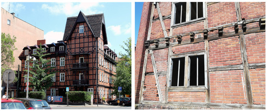
Figure 1.
Taken as example, selected historic buildings with difficult access to sampling or testing (source: authors’ own study).
As evidenced by numerous studies [5,6,7,8,9,10,11,12,13,14], it is most accurate to consider wood—reflecting the behaviour of this material under the influence of mechanical stress—as an elastic-visco-plastic body, having simultaneously heterogeneous and porous characteristics [6,7,8,9,15,16,17,18,19,20]. The dependence of the physical properties of wood on the direction of the anatomical structure of tree trunks was confirmed in the 1920s. Wood’s anisotropy results from the arrangement of its structural elements [21]. For most wooden objects, the assumption of orthogonal anisotropy (orthotropy) is the most applicable [13,14,19,21,22,23]. When analysing the structure of wood at the macroscopic, microscopic, and submicroscopic levels [6,15,24,25], there are distinguishable regular elements, irregular elements (heterogeneities), and defects. Each level is characterised by different reasons for wood anisotropy. Additionally, we can distinguish five structural levels affecting wood anisotropy [26]: the matter of wood cells, the cell wall, the cell, the group of cells, and various types of wood tissue as a whole. At the submicroscopic level, the elongated middle layers of cell walls act as supports. They are the thickest elements and contain microfibrils that are practically parallel to the longitudinal axis of the cell. The strength and elasticity modulus of cell walls in directions transverse to the longitudinal axis of the cell is significantly lower than that of cell walls along the cell axis [26]. Total deflection of wood under the action of external forces usually consists of elastic immediate deflection, elastic deflection developing over time (called elastic retardation or elastic deflection), which can be considered elastic-sticky deflection, and plastic deflection—also developing over time. The curvature of annual rings and their different orientation against the edge of a sufficiently large wood object additionally can blur the differences between the different directions in the plane perpendicular to wood fibres. In such a case, it is most justified to treat wood as a transversal-isotropic (monotropic) body [16,26,27]. In its structure, wood very often contains knots and cracks, which may affect its strength parameters. In practice, since the 1970s, a new discipline related to the viscoelastic-plastic nature of wood has been developed, known as the theory of damaged viscoelastic materials (DVM). It considers cracks, gaps, and other wood defects (mainly knots) as natural inhomogeneities of wood. The damaged viscoelastic materials theory (DVM) has been developing primarily in Denmark and Canada [28,29]. The theory, confirmed experimentally, allows for tracking the formation and development of cracks in the vicinity of the analysed defects, i.e., material creep, and estimating wood quality, i.e., its durability and long-term strength—here called “residual strength” [10,11,29,30,31]. The material intended for testing the mechanical and physical properties of wood should be collected in accordance with the purpose of the planned measurements and with the requirements concerning the representativeness of samples and their statistical size [32,33]. Destructive tests require collecting a large number of samples of a predetermined size and their appropriate conditioning. They may also consist of, for example, the examination of cores taken by drills with special tips [25]. Usually, conservators of monuments do not agree with the use of invasive methods. In this case, it is worth using non-destructive testing to determine the parameters of bending strength. Among non-destructive tests, the most popular are:
- Quality assessment of wooden structural elements, consisting of the propagation of acoustic waves, which should be performed at a specific humidity, density, and assessment of wood defects, as these factors have a significant impact on the speed of wave propagation. However, it is useful for many elements made of wood of a similar anatomy, species, and shape. The method should not be considered as reliable without verifying the results using other methods [1,34],
- Wood structure by means of X-ray examination (X-ray chamber), which allows for volumetric examination with real-time imaging. Elements of variable thickness and shape are ideal for tests using this method, which allows for the examining of critical zones with a significant intensity of defects, impurities, or fibre thinning. An image processing system can indicate various defects in the wood structure. In order for wooden elements to be examined with an X-ray chamber, their dimensions must not exceed 700 × 1200 mm [34],
- Assessment of the quality and mechanical properties of wooden structural elements using the sclerometric method with a Schmidt hammer (WoodPecker by DRC). The test is easy to perform, however, the instruction informs that it should be carried out from the front of the beam with a specific spacing of test points and the results should be referred to the parameters given in the correlation of the needle penetration depth and elasto-mechanical properties [24,35].
In the literature on the subject, there are no analyses of the correlation of strength parameters for wooden beams measured across and along wooden fibres using a sclerometric device. The authors conducted an experiment by modeling tests to analyse the obtained values and create guidelines for several variants of in situ tests. Testing softwood with the use of a Schmidt hammer is innovative. At present, there are no tables or diagrams on the basis of which the strength class can be read. The aim of this experiment was to create such tables and diagrams, from which, based on the correlation between the side and the head of the beam using in-situ tests and the sclerometric method, it will be possible to obtain the bending strength of an existing wooden beam. It is particularly important in case of historic buildings, where most often there is only a possibility, allowed by conservators, to perform tests from the side of the beam, while all research procedures refer to conducting tests from the front of the beam.
2. Materials and Methods
For the tests, samples of pine and spruce wood were used. The wood was taken from one shipment of sawn timber. For comparison purposes, the structure of the wood was tested in the laboratory, and the analysis was performed using a TESKAN VEGAN-3 microscope (TESKAN, Brno, Czech) at 50× and 500× magnification (Figure 2).
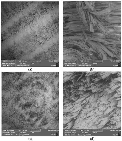
Figure 2.
Structure of pine wood (a,b) and spruce wood (c,d), from one batch of sawn timber.
The number of samples for density and humidity tests was adopted in accordance with the standard [36] and amounted to 40, since this is the smallest permissible number of samples compliant with the provisions. However, for the strength tests, the number of samples was selected considering the number of tests carried out using the non-destructive method. A total of 10 spruce wood and 10 pine wood samples were used for the study. The number of tests performed using the non-destructive Schmidt hammer method was 80 hammer blows from the head and 120 hammer blows from the side for the spruce wood and pine wood elements. As the wood was from one batch, the result from 1 test was taken as 1 sample for the species of wood, i.e., the smallest permissible number of samples, which resulted in 40 tests carried out with a Schmidt hammer (Gilson, Inc., Middleton, WI, USA).
The pine wood samples were 10 beams with dimensions of 60 × 60 × 1260 mm, conditioned in the open air without impregnation. Macroscopic examination showed that the elements had knots. On the other hand, the spruce wood samples were beams with dimensions of 20 × 20 × 300 mm, also conditioned in the open air and then technically dried to a moisture content of 10 ± 2%. The spruce wood samples also had knots and were not impregnated. Figure 3 and Figure 4 show the samples prepared for testing. During the test, the air temperature was 22.1 °C and relative air humidity was 51.1%. The values were checked with a TROTEC BP25 Dual-laser NO.150321542 laser scanner (Accurate, Auckland, New Zealand). All elements were cut from hardwood. The wood intended for the experiment was without defects, cracks, and twists of fibers with a few knots. The distance of the rings was not measured. The raw material was harvested in the winter and stored under a canopy for about 3 years.
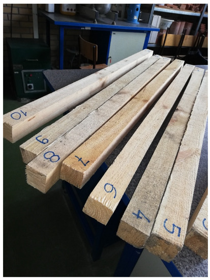
Figure 3.
Pine wood elements.
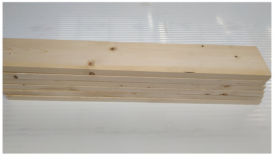
Figure 4.
The elements of spruce wood before trimming to 20 × 20 × 300 mm.
2.1. Determination of Moisture Content in Wood
Moisture content in the wood samples was determined using the dryer-weight method according to [37] prior to strength tests. Before the tests, all samples were kept under normal conditions. The wood samples were weighed with an accuracy of 0.01 g. Then, they were conditioned in a wood drying chamber at a temperature of 103 (±2) °C. The drying process continued until the difference between two consecutive weighings, which were carried out at two-hour intervals, was less than 0.1%. The samples were weighed immediately after they were removed from the dryer. In addition, the moisture content test was carried out using a non-destructive method with a TFA Dostmann/Wertheim No. 30.5502 07/09 device (TFA Dostmann, Wertheim-Reicholzheim, Germany). The moisture content in the pine wood samples was 7% and the moisture content in the spruce wood samples was 11%.
2.2. Wood Density
Wood density was determined by the stereometric method compliant with [36]. Before the strength tests, the samples were measured along the appropriate symmetry axes. The measurement was made with an accuracy of 0.01 mm using a calliper. Their mass was determined with an accuracy of 0.01 g. Wood density ρw with moisture W was calculated according to formula:
where:
- mw—mass of the sample before drying with moisture content W [g],
- aw, bw, lw—linear dimensions of the cross-section and the length of the sample with moisture content W [mm],
- Vw—volume of the sample with moisture content W.
The results were corrected according to the standard [36] as the humidity of the samples was below 12%. This meant an increase in density by 0.5% for each moisture percentage point of the samples.
A characteristic feature of wood is the anisotropy of its anatomical structure, as a result of which we can distinguish three anatomical directions in wood: radial, tangential, and along the fibres. The examination of the effect of the anatomical direction was carried out on appropriately selected and conditioned samples. The density of each of the 40 samples was determined by taking three measurements in the longitudinal, tangential, and radial direction.
2.3. Determination of Static Bending Strength
The test was performed under reference conditions, i.e., at an air temperature of 20 °C and a moisture content of 65% in accordance with [38,39]. Bending was performed with two concentrated forces with total value of F in the direction perpendicular to the radial section of the wood sample. The samples were placed freely, symmetrically on two supports, in a way that allowed the load to be transferred by the thrust to the sample in the middle of its length. The distance between the supports was 12 times greater than the sample’s height. The dimension between the thrust and the support was equal to six times the value of the sample’s height (Figure 5). The measuring stand was an advanced system for IN-STRON strength tests (Instron, Norwood, MA, USA), which included a device for strength tests, digital control system, high-speed data transmission interface, measuring head of 300 kN with interchangeable accessories, and computer set integrated with the INSTRON system, Bluehill 2 software (Bluehill®, Norwood, MA, USA) generating a tabular summary of results along with diagrams.
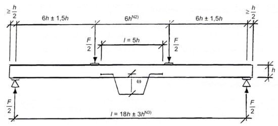
Figure 5.
Scheme of the bending strength test according to [39].
The test on the samples started with applying a pre-load (F) of 0.5 kN, and then loading it with a constant speed of 0.3 kN/min. The load rate was determined tentatively, so that the maximum load was reached after 300 ± 120 s (Figure 6 and Figure 7). After completing the tests, a diagram was prepared for each sample, showing the relationship between the load and resultant deflection. The deflection value was read from the data provided by the measuring head sensor, saved in a tabular form by the software of the strength testing device.
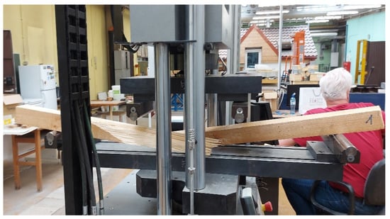
Figure 6.
Bending strength test of the spruce wood element.
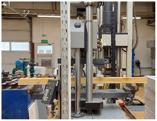
Figure 7.
Bending strength test of the pine wood element.
The values of bending strengths were calculated by substituting the destructive force in the following formula:
where:
- Fmax—maximum load [N],
- l—span of the sample measured between supports [mm],
- b—width of the sample [mm], h—height of the sample [mm].
2.4. Testing with a Light Schmidt Hammer
This non-destructive method allows, to a limited extent, for the assessment of the mechanical properties of wood (resistance and deformability), as well as for the determination of the condition of protection of wooden elements. For this purpose, a needle with a diameter of 2.5 mm and a length of 50 mm was used, which had a conical tip with an angle of 35°. It was made of high-hardness steel (60 HRC).
The test was performed in a standing position to avoid the adverse effects of gravity. A testing instrument with a needle was placed against the edge of the element at 90°, and then it was hit five times with a Schmidt hammer. Next, the recess depth was measured with a system with a dial gauge with an accuracy of 0.01 mm. Each of the four edges was tested three times (Figure 8 and Figure 9).
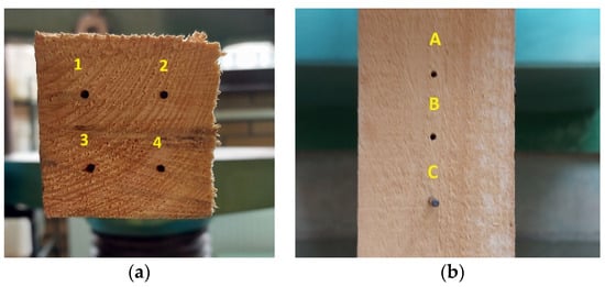
Figure 8.
Measurement points—(a) the needle recess along fibres (1, 2, 3, 4), (b) across fibres (A, B, C).
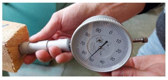
Figure 9.
Reading from the needle recess in the wooden element along fibres.
3. Results
The wood density results were:
- −
- For pine wood—mean density ρmean = 432 kg/m3, variation coefficient 8.9%, standard deviation 39.44, and the 5% density quantile of the test was 362.38 kg/m3,
- −
- For spruce wood—mean density ρmean = 427.46 kg/m3, variation coefficient 9.2%, standard deviation 29.44, and the 5% density quantile of the test was 378.88 kg/m3.
Schmidt hammer tests for pine wood were carried out on 10 beams. The first 10 measurements for the 10 spruce beams were adopted for further analysis and experiments in order to compare the obtained results. For the spruce wood elements, the bending strength was determined for each element individually. The results for the 20 samples using the INSTRON press are shown in Figure 10, and a summary of the results of the bending strength test for the 10 samples of spruce wood is summarized in Table 1.
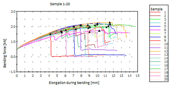
Figure 10.
Results of the bending strength test for spruce wood elements obtained during the test at the INSTRON stand.

Table 1.
Results of the bending strength test for spruce wood elements.
For the pine wood elements, the bending strength was determined for each element individually. Figure 11 shows the relationship between the elongation during bending and the bending force for each of the 10 elements. The destructive force for the samples from two to ten ranged from 6 to 11 kN, while the destructive force for the first sample significantly differed and amounted to approx. 15 kN. The bending strength of the individual samples of pine and spruce wood were calculated using Formula (2) and is presented in Table 2 and Table 3.
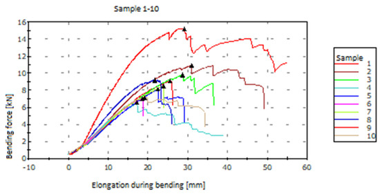
Figure 11.
Results of the bending strength test for pine wood elements obtained during the test at the INSTRON stand.
Table 2.
Results of Schmidt hammer tests for spruce wood elements and bending strength obtained in the destructive test in accordance with [38].
Table 3.
Results of Schmidt hammer tests for pine wood elements and bending strength obtained in the destructive test in accordance with [38].
Table 2 summarizes the mean results from the Schmidt hammer test for six spruce wood samples carried out from the head and the side of the element. The maximum standard deviation from the head was 2.84 and from the side was 3.04. The ratio between the needle recess from the side to the needle recess from the head ranged from 0.64 to 0.76, thus it averaged 0.70.
Figure 12 shows the results of the Schmidt hammer test at individual points conducted from the front of the 10 pine wood beams. Figure 13 shows the needle recess in these elements from the side. There were noticeable differences in the results for the individual points due to the non-uniform structure of the wood. Additionally, for both the pine and spruce wood elements, the needle recess from the side (across fibres) was smaller than from the front (along fibres).
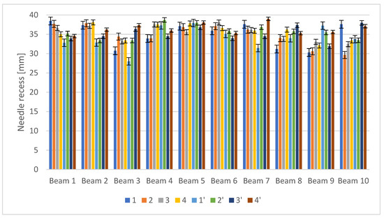
Figure 12.
Needle recess from the head of pine wood beams. 1, 2, 3, 4, 1′, 2′, 3′, 4′—measurement points—the needle recess along fibres.
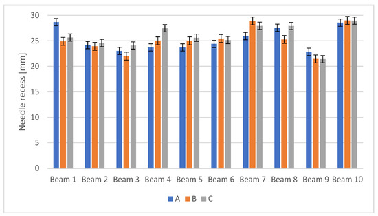
Figure 13.
Needle recess from the side of pine wood beams. A, B, C—measurement points—the needle recess across fibres.
Table 3 summarizes the averaged results of the needle recess for each of the 10 pine wood elements from the side and from the front. The maximum standard deviation from the head was 2.77 and from the side was 1.62. For the pine wood samples, the ratio of the recess across fibres to the recess along fibres was also provided, ranging from 0.66 to 0.84, thus averaging 0.72.
Figure 14 and Figure 15 show the correlation between the mean needle recess from the side of the pine wood elements (Figure 14) and the spruce wood elements (Figure 15) and their bending strength tested using a destructive method. It was noticeable that the greater the recess, the lower the strength of the element.
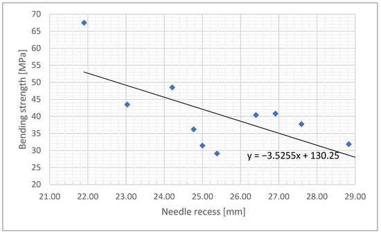
Figure 14.
Correlation between the needle recess from the side of the element and its bending strength for the pine wood elements.
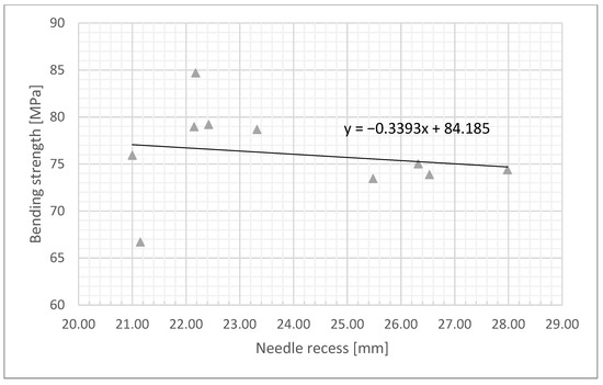
Figure 15.
Correlation between the needle recess from the side of the element and its bending strength for spruce wood.
A statistical analysis of the results is presented in Figure 14 and Figure 15. The analyses were performed using the Pearson correlation coefficient, which is expressed by Formula (3) taken from [40].
and Spearman’s rank correlation coefficient [40]
where:
- —squares of differences between ranks of corresponding values xi i yi,
- n—number of data pairs.
Table 4 presents the results of the Pearson and Sperman correlation. By analysing the graphs shown in Figure 14 and Figure 15, it can be seen that the pattern of the points has a shape similar to an inverted parabola. Therefore, there was no linear relationship here and the correlation relationships must be described with non-linear functions. As a confirmation, it can be stated that with the linear trend line for Figure 14, the coefficient of determination was R2 = 0.447, while with the polynomial function R2 = 0.672. Similarly for Figure 15, with the linear trend line, the coefficient of determination was R2 = 0.032, while for the polynomial function R2 = 0.189.
Table 4.
Results of the non-parametric test of the correlation coefficient significance.
The Pearson correlation analysis presented in Table 4 shows a poor correlation coefficient for both the pine wood and spruce wood elements because
The obtained results confirmed that it was difficult to obtain linear parameters demonstrating a sufficient repeatability of parameters by non-invasive methods. The wood material, taken for testing from one batch, exhibited different mechanical properties. In order to verify strength parameters, as shown by the tests with the needle recesses being not directly proportional to the obtained strengths (Table 2 and Table 3, Figure 14 and Figure 15), the obtained strength parameters by a non-invasive method should always be verified by an invasive method to obtain accurate data for further statistical analyses of working elements.
However, the obtained results of the needle recess of the side for the beam head can be considered uniform and in the case of obtaining material for the head-side tests, the parameter 0.7 can be taken as a correction/correlation parameter.
4. Discussion
The tests with the use of a Schmidt hammer for softwood were innovative. Their objective was to find the correlation between the needle recess from the side and from the head of the beam. The authors assumed that such a relationship would help in non-invasive examination of wooden elements in historic buildings, where most measurements can be made from the side of the beam, not from its head, since it remains inaccessible.
The authors of the work [41] provide the results of pine wood tests depending on the place of sampling, analysing post-agricultural and typically forest areas. Based on the results, they found that the wood of young pine had a density of 500–600 kg/m3, while the wood of mature pine (80 years old) had a density of 570–630 kg/m3.
The presence of resin in the wood tissue may have been a factor disturbing the achieved results since wood has a higher density when it contains resin. The zones of the wood saturated with resin were denser, but this did not lead to an increase in compressive strength, bending strength, nor the modulus of elasticity. In the works [42,43,44], the authors referred to the diagnostics of historic buildings in order to use them as sacred, museum, hotel, educational, or recreational buildings, providing the most advantageous methods of multidisciplinary and sustainable protection of monuments. The authors described the technical and legal problems related to the adjustment to modern construction requirements, i.e., safety of use, fire safety, and proper energy performance. A completely different matter is to assess the load-bearing capacity of historic buildings for which modern load standards cannot be used because most of these structures would not fulfill contemporary requirements. The works [45,46,47,48] showed the method of calculating the load-bearing capacity for historic objects and explained the accepted deviations.
The work [3] proposed the use of a diagnostic method with the use of laser scanning, thanks to which large fragments of a historic ceiling were not damaged. Based on the tests carried out in selected sample holes, the structural system of floor beams as well as the construction and structure of the floor were identified, which allowed for assessing their load-bearing capacity and the manner of further use.
The diagnostics of historic buildings also concerns the issue of moisture content, which was described in detail in relation to historic buildings in [4]. For the purpose of the work [48], the construction materials, for which the reduction in relative moisture content was measured, were investigated not only to recommend them for use in passive buildings, but also for the reconstruction or renovation of historic buildings. The studies quoted in the paper were carried out at humidity of 65% in accordance with [38,49].
The authors of the work [50] state that nowadays, due to the widespread thermal modernisation of buildings, this subject is also beginning to apply to historic buildings. Subsequently, it is important to check the technical condition and load-bearing capacity of wooden elements when making a decision on their thermal modernisation.
The authors of the work [33] indicated that it is important to understand how the mechanical properties of wood change depending on its heterogeneity, the orientation of the sample’s position in relation to the directions of anisotropy, and its natural defects. The testing material was obtained from pine sawn timber, which was based on the four-sided planing process. The wood was subjected to strength tests, determining for the appropriate groups of samples the following parameters: modulus of elasticity in static bending and static bending strength. The influence of wood anisotropy on the elastic and strength properties of wood was investigated. It was shown in the work [33] that it results from the orientation variability of wooden elements and the direction of the load in relation to the main directions of anisotropy.
The presence of knots and three levels of non-homogeneous wood structure in the tested samples significantly increase the variability range of the elasticity modulus. Earlier studies showed that some defects in pine and spruce wood are more common than others and therefore have a more significant impact on the deterioration of roundwood quality [51,52,53]. In the work [54], the authors presented the study of the mechanical properties of walnut samples, which indicated a tendency for higher static bending strength of wood samples with more regular annual growth. The structure and density of wood are also related to the social position of a tree in a forest, as well as its age [55,56]. The mechanical properties of wood take into account, inter alia, wood anisotropy, which results from the variable orientation of examined wooden elements and the direction of applied loads in relation to the main direction of wood anisotropy [9,51,57,58,59,60,61,62].
The strength properties of wood depend primarily on the decomposition of cellulose polymers in the cell wall, which forms the supporting skeleton of the wood, and on the amorphous (amorphous) lignin filling the free spaces of the skeleton. Cellulose affects the elastic properties as well as the lignin—plastic ones. The average static bending strength of wood is 75 to 98 MPa, which is lower than the tensile strength but greater than the compressive strength [63]. In the example of pine and spruce wood samples, the authors [63] present in Table 5 the effect of knots on the reduction in wood bending strength in the tangential and radial directions.
Table 5.
Effect of knots on the tangential and radial bending strength of pine and spruce wood [63].
In the work [64], a qualitative comparison was made of the behaviour of mixed glued pine wood in the outer layers and poplar wood in the inner layers. Single-species laminated timber of poplar and pine samples were used as control systems. The study included destructive four-point bending tests and three non-destructive methodologies: the numerical model of the finite element method, the semi-analytical model based on the parallel axis theorem, and acoustic resonance. Excellent agreement was obtained between the experimental and numerical results. Despite the small number of samples, the results showed that the use of poplar as a low-quality species in the inner layers of glued laminated timber may be a promising technology for reducing the weight of the material while maintaining good mechanical properties of pine wood. The paper [65] contains an evaluation of the possibility of producing pine wood glued-construction elements. It was assumed that pine wood is not free from defects such as knots. The bending strength was obtained from a four-point bending test and was not related to the class of the wood. The average bending strength of the beams was 36.6 N/mm2.
The use of active thermography in wood diagnostics, in particular in determining the knot area coefficient in elements covered with paint coatings, is discussed in [66]. Moreover, based on thermal images, the locations of points for semi-destructive tests were determined. Active thermography studies were carried out on three types of wood elements: fir, pine, and spruce. The samples were covered with various layers of paint coatings and primers to reflect the actual historic design elements. The obtained thermal images allowed for the location of knots due to the temperature difference between the solid wood and the knots present in it. This study showed that active thermography can be an effective method for indicating areas in which the test should be performed to properly assess the technical condition of elements covered with polychrome. Tests and examinations aiming at identifying and assessing the technical condition of buildings with wooden elemets that fall under monument protection require referencing to the provisions included in [67,68,69]. Another condition that must be met in order to undertake implementation activities in historic buildings is to preserve their original, historic form as much as possible, ultimately leading to their conservation and restoration. The assumptions in [69] state that realisation activities undertaken on monuments are aimed at preserving and revealing the historic, aesthetic value of these objects and are based on respecting the old substance of elements constituting authentic documentation of the past. Strengthening historic buildings is allowed with the use of modern conservation, construction, and engineering techniques while maintaining the principles of the conservation doctrine. Therefore, each maintenance plan applying to historic buildings requires qualitative information obtained from the direct observation of both material deterioration as well as structural failures. The conclusions drawn from the performed tests are guidelines for the development of work schedules, the result of which will be the processes directed at removing the causes of destruction and eliminating their effects. Among the many modern methods, including non-destructive or quasi-non-destructive solutions, the following methods can be distinguished: the elastic wave method and the drilling resistance method. The sclerometric method proposed in this material, in particular by the described dependencies of the measurement results coming from the method of carrying out reconnaissance tests of surface wooden structures, will allow the obtaining of data that will help to minimize interference in the structure of the historical tissue of structural elements, i.e., roof trusses. For structural and building analyses that aim at assessing the impact of destruction on the strength of load-bearing elements, which limits their further safe use, the information on the actual state of the strength parameters of the tested cross-section of load-bearing elements is essential analytical data. Historic Building Information Modeling (HBIM) [70] is an important step in the renovation task. In situ studies fill the space of real parameters considered by designers and investors. The conducted analysis is an attempt to obtain the correlation of the load-bearing parameters of structural elements, which, due to their historical background, must not be damaged. The use of simple methods is repeatedly preferred by many engineers. As studies have shown, the parameters measured by the sclerometric method give a clear correlation of strength parameters along and across the fibers. Analytical modeling of beams should take into account a number of parameters (knots, moisture content, etc.). The results obtained in the laboratory tests showed a great variety (Table 2 and Table 3), which only confirmed that wood is a difficult material to analyze.
5. Conclusions
In order to determine the strength parameters of structural elements and perform the possible verification of in situ tests, it is advisable to take samples, i.e., to use invasive methods, which are more accurate. To ensure the reliability of the conducted studies, the damaged viscoelastic materials (DVM) method sets the number of samples in the test batch from a dozen to several dozen. However, due to the historical importance of the buildings in question, it is recommended to keep sampling to a minimum. Non-destructive bending strength testing with a light Schmidt hammer is a non-invasive method that can determine the initial strength parameters in situ. Tests with the use of a Schmidt hammer for softwood are innovative. At present, there are no tables or diagrams on the basis of which the strength class for low-class wood can be read. The objective of this experiment was to create in the future strength tables and correlation diagrams of plane tests of historical wooden elements using the sclerometric method for, i.e., degraded wood with a strength lower than 40 MPa. The producers of the device defined guidelines related to the number of strokes when inserting the needle into the material and the exact place of insertion. The experiment showed that, for the study of softwood—pine—there was a problem with a too-big needle recess after 5 strokes. Therefore, for softwood, it is worth considering a smaller number of strokes. In order to determine the correlation of the obtained parameters, tests from the front and the side of the beams were carried out. In all cases, the needle recess across the fibres was smaller than along the fibres. A correlation between the recess from the side and the recess from the front was noticed, amounting to an average of 0.72 for spruce elements and 0.70 for pine elements. The authors of this article indicate that the confirmation of this observation requires conducting further research on various types of wood. It should also be noted that the material collected from one batch of sawn timber had a different structure, which was verified by SEM imaging. Obtaining reliable results of experiments entails collecting a large number of research samples.
Modeling wood numerically is, to some extent, a simplified issue that assumes wood to be an orthotropic, homogeneous material. In fact, wood is an anisotropic, very heterogeneous material. Wood heterogeneity occurs at least on two levels: on the “micro” scale in the forms of rings, and on the “macro” scale in the form of knots. In this case, it is pointless to discuss the discretisation of the continuous field of random material properties, because there is a natural, commonly known and clearly visible discretisation of the material structure and its properties [71]. In bending beams, the presence of material defects in the wood in the tension zone is particularly important. The analysis of wood (on the technical scale, construction wood) as an anisotropic material is practically impossible—the y and z axis orientation are hardly ever included. Adopting wood as an isotropic material is too much of a simplification. Therefore, undoubtedly, the most appropriate method of assessing the technical condition of wooden elements are destructive methods, since all non-destructive methods should not be used without verifying the results with other methods. In addition, the results obtained by non-destructive methods are often very difficult to interpret. According to the literature analysis, the most appropriate method for determining the strength of embedded wood is destructive methods, all non-destructive methods should not be used without verifying the results by other methods. Any deviation from the correct structure of the wood (such as cracks or fiber twists) affects its strength and thus its sclerometric tests, which are interpreted and not directly read from the device.
The method described in this paper will allow for obtaining the necessary data for effective expertise assessment regarding the safety level of structural elements of historic wooden load-bearing structures, which is vital for making conservation decisions.
Author Contributions
Conceptualization, B.K. and A.S.-G.; methodology, B.K.; software, B.K.; validation, B.K. and A.S.-G.; formal analysis, A.S.-G.; investigation, R.P.; resources, M.T.; data curation, B.K.; writing—original draft preparation, B.K. and M.T.; writing—review and editing, A.S.-G.; visualization, R.P.; supervision, R.P.; project administration, A.S.-G.; funding acquisition, R.P. All authors have read and agreed to the published version of the manuscript.
Funding
This research received no external funding.
Institutional Review Board Statement
Not applicable.
Informed Consent Statement
Not applicable.
Data Availability Statement
Not applicable.
Conflicts of Interest
The authors declare no conflict of interest.
References
- Nowak, T. Analiza Pracy Statycznej Zginanych Belek Drewnianych Wzmacnianych Przy Użyciu CFRP [Analysis of Static Work of Bent Wooden Beams Reinforced with CFRP]; PRE Report no. 4/07; PRE: Wrocław, Poland, 2007. [Google Scholar]
- Nowogońska, B. Intensity of damage in the aging process of buildings. Arch. Civ. Eng. 2020, 66, 19–31. [Google Scholar] [CrossRef]
- Szymczak-Graczyk, A.; Walczak, Z.; Ksit, B.; Szyguła, Z. Multi-criteria diagnostics of historic buildings with the use of 3D laser scanning (a case study). Bull. Pol. Acad. Sci. Tech. Sci. 2022, 70, e140373. [Google Scholar] [CrossRef]
- Ksit, B.; Szymczak-Graczyk, A.; Nazarewicz, B. Diagnostics and renovation of moisture affected historic buildings. Civ. Environ. Eng. Rep. 2022, 1, 59–73. [Google Scholar] [CrossRef]
- Dinwoodie, J.M. Timber—A review of the structure—mechanical property relationship. J. Microsc. 1975, 104, 3–33. [Google Scholar] [CrossRef]
- Kollman, F.P. Verformung Und Bruchgeschehen Bei Holz Als Einen Anisotropen, Inhomogenen, Porigen Festkörper; VDJ 520; VDJ: Berlin, Germany, 1967. [Google Scholar]
- Miller, R.B. Wood Handbook—Wood as an Engineering Material. Forest Products Laboratory, Forest Service U.S. Department of Agriculture: Madison, WI, USA, 1999. [Google Scholar] [CrossRef]
- Thibaut, B.; Gril, J.; Fournier, M. Mechanics of wood and trees: Some new highlights for an old story. Comptes Rendus De L’academie Des. Sci. Ser. IIB Mech. 2001, 329, 701–716. [Google Scholar] [CrossRef]
- Mishnaevsky, L.; Qing, H. Micromechanical modeling of mechanical behavior and strength of wood: State of the art review. Comput. Mater. Sci. 2008, 44, 363–370. [Google Scholar] [CrossRef]
- Walczak, A.; Pieniak, D.; Oszust, M.; Blukacz, M.; Ogrodnik, P. Comparative study of the effect of scale in the modified wood compression test. Inst. Nauk. Wydawniczy SPATIUM 2014, 15, 122–126. [Google Scholar]
- Noskowiak, A.; Pajchrowski, G.; Szumiński, G.; Jabłoński, L. Strength and modulus of elasticity of pine structural round timber. For. Wood Technol. 2015, 92, 300–306. [Google Scholar]
- Krzysik, F. Nauka o Drewnie [Science about Wood]; PWN: Warsaw, Poland, 1974. [Google Scholar]
- Turrini, G.; Piazza, M. Investigations in situ for the determination of the mechanical characteristics of the wooden structures. In Proceedings of the CIAS Seminar on the Topic Actuality of the Testing for the Storage of Materials and Structures, Bolzano, Italy, 24–25 May 1991; pp. 183–198. [Google Scholar]
- Fojutowski, A.; Noskowiak, A.; Kot, M.; Kropacz, A.; Stangierska, A. The assessment of mechanical properties of wood treated with ionic liquids. Drew. Pr. Nauk. Doniesienia Komun. 2010, 53, 21–37. [Google Scholar]
- Rosa, R.J. Wood Handbook: Wood as an Engineering Material. Forest Products Laboratory, Forest Service U.S. Department of Agriculture: Madison, WI, USA, 2010. [Google Scholar] [CrossRef]
- Sobolev, J.S. Drevesina Kak Konstrukcionnyj Material, Izd; Lesnaja Promyšlennost: Moskva, Russia, 1979. [Google Scholar]
- Kopač, J.; Šali, S. Wood an important material in manufacturing technology. J. Mater. Process. Technol. 2013, 133, 133–142. [Google Scholar] [CrossRef]
- Malaga-Toboła, U.; Łapka, M.; Kurek, M.; Łukasiewicz, M.; Kocira, S. Wood modification methods. Przemysł Chem. 2017, 7, 1563–1566. [Google Scholar] [CrossRef]
- Goodman, J.R.; Bodig, J. Orthotropic elastic properties of wood. J. Struct. Div. 1970, 96, 2301–2319. [Google Scholar] [CrossRef]
- Madsen, B. Structural Behaviour of Timber; Timber Engineering Ltd: North Vancouver, BC, Canada, 1992. [Google Scholar]
- Sobolev, J.S. Zavisimost’ predela pročnosti materiala kleenych derevjannych konstrukcji ot absoljutnych razmerov obrazcow pri izgibe. Mech. Obrab. Drev. 1975, 5, 5. [Google Scholar]
- Beljankin, F.P.; Jacenko, W.F. Deformativnost’ I Soprotivljaemost’ Drevesiny Kak Uprugo—Vjazko—Plastičeskogo Tela, Izd; Akademii Nauk USSR: Kiev, Ukraine, 1957. [Google Scholar]
- Nielsen, L.F. Wood as a Cracked Viscoelastic Material; Forintek, Western Forest Products Laboratory: Vancouver, BC, Canada, 1985. [Google Scholar]
- Menditto, G.; Bufarini, S.; D’Aria, V.; Massaccesi, M. Experimental results of an extensive series of tests to trace the correlation curves for the wood sclerometer. In Proceedings of the 11th National Conference on Non Destructive Testing Monitoring Diagnostics, Milan, Italy, 13–15 October 2005. [Google Scholar]
- Żaboklicki, A. Rehabilitacja drewnianych konstrukcji w zabytkowych obiektach architektury i budownictwa [Rehabilitation of wooden structures in historic buildings and architecture]. In Proceedings of the Konferencja Naukowo-Techniczna, Konserwacja, Wzmacnianie i Modernizacja Budowlanych Obiektów Historycznych i Współczesnych [Science and Technology Conference, Conservation, Reinforcement, and Modernization of Historical and Contemporary Construction Facilities], Kielce, Poland, 22–23 November 2001; pp. 163–179. [Google Scholar]
- Bodig, J.; Jayne, B. Mechanics of Wood and Wood Composites; Van Nostrand Reinhold Company: New York, NY, USA; Cincinnati, OH, USA; Toronto, ON, Canada; London, UK; Melbourne, Australia, 1982. [Google Scholar]
- Dzbeński, W.; Kozakiewicz, P.; Krzosek, S. Wytrzymałościowe Sortowanie Tarcicy Budowlano—Konstrukcyjnej [Strength Sorting of Construction Sawn Timber]; Wydawnictwo SGGW: Warsaw, Poland, 2005. [Google Scholar]
- Farruggia, F.; Perre, P. Microscopic tensile test in the transverse plane of earlywood and latewood parts of spruce. Wood Sci. Technol. 2000, 34, 65–82. [Google Scholar] [CrossRef]
- Gustafsson, P.J. Crack propagation in wood and wood products. In Proceedings of the Second International Conference of the ESWM, Stockholm, Szwecja, 8–10 December 2003. [Google Scholar]
- Jayne, B.A. Theory and Design of Wood and Fiber Composite Materials; Orthotropic Elasticity; Syracuse University Press: Syracuse, NY, USA, 1972. [Google Scholar]
- Bucur, V. Nondestructive Characterization and Imaging of Wood; Springer: Berlin/Heidelberg, Germany, 2003. [Google Scholar]
- Kokociński, W. Nieniszcząca Metoda Badania Jakości Drewna W Konstrukcjach Budowlanych [Non-Destructive Method of Wood Quality Testing in Building Structures]; Zeszyty Problemowe, Badania nieniszczące: Warsaw, Poland, 2001; pp. 231–236. [Google Scholar]
- Malaga-Toboła, U.; Łapka, M.; Tabor, S.; Niesłony, A.; Findura, P. Influence of wood anisotropy on its mechanical properties in relation to the scale effect. Int. Agrophys. 2019, 33, 337–345. [Google Scholar] [CrossRef]
- Linan, C.R.; de Hita, P.R.; de Cozar, J.C.G. Application of ultrasonic techniques, as a non destructive method, for the evaluation of timber structures. In Proceedings of the 5th World Conference on Timber Engineering, Montreux, Switzerland, 17–20 August 1998; pp. 806–807. [Google Scholar]
- DRC. Manual Woodpecker 16; Instrukcja użytkowania Młotka Schmidta do Drewna Firmy DRC [DRC Company’s Schmidt Wood Hammer User Manual]; DRC: Warsaw, Poland, 2016. [Google Scholar]
- PN-EN 384:2011; Drewno Konstrukcyjne Oznaczanie Wartości Charakterystycznych Właściwości Mechanicznych I Gęstości [Structural timber—Determination of Characteristic Values of Mechanical Properties and Density]. Polski Komitet Normalizacyjny; Polish Committee for Standardization: Warsaw, Poland, 2011.
- PN-EN 13183-1:2004; Moisture Content of a Piece of Sawn Timber. Part 1: Determination by Oven Dry Method. Polski Komitet Normalizacyjny; Polish Committee for Standardization: Warsaw, Poland, 2004.
- PN-EN 408+A1:2012; Timber Structures. Structural Timber and Glued Laminated Timber. Determination of Some Physical and Mechanical Properties. Polski Komitet Normalizacyjny; Polish Committee for Standardization: Warsaw, Poland, 2012.
- PN-D-04103:1977; Drewno. Oznaczanie Wytrzymałości Na Zginanie Statyczne [Determination of Static Bending Strength]. Polski Komitet Normalizacyjny; Polish Committee for Standardization: Warsaw, Poland, 1977.
- Rahman, N.A. A Course in Theoretical Statistics; Charles Griffin and Company: New York, NY, USA, 1968. [Google Scholar]
- Kozakiewicz, P.; Jankowska, A.; Mamiński, M.; Marciszewska, K.; Ciurzycki, W.; Tulik, M. The Wood of Scots Pine (Pinus sylvestris L.) from Post-Agricultural Lands Has Suitable Properties for the Timber Industry. Forests 2020, 11, 1033. [Google Scholar] [CrossRef]
- Delegou, E.T.; Mourgi, G.; Tsilimantou, E.; Ioannidis, C.; Moropoulou, A. A multidisciplinary approach for historic buildings diagnosis: The case study of the Kaisariani monastery. Heritage 2019, 2, 1211–1232. [Google Scholar] [CrossRef]
- Ascione, F.; Ceroni, F.; De Masi, R.F.; de’Rossi, F.; Pecce, M.R. Historical buildings: Multidisciplinary approach to structural/energy diagnosis and performance assessment. Appl. Energy. 2019, 185, 1517–1528. [Google Scholar] [CrossRef]
- Fais, S.; Casula, G.; Cuccuru, F.; Ligas, P.; Bianchi, M.G. An innovative methodology for the non-destructive diagnosis of architectural elements of ancient historical buildings. Sci. Rep. 2018, 8, 4334. [Google Scholar] [CrossRef]
- Lourenço, P.B. Computations on historic masonry structures. Prog. Struct. Eng. Mater. 2002, 4, 301–319. [Google Scholar] [CrossRef]
- Iringová, A.; Idunk, R. Solution of fire protection in historic buildings. Civ. Environ. Eng. 2016, 12, 84–93. [Google Scholar] [CrossRef][Green Version]
- Gołdyn, M.; Urban, T. Failures of the Cast-Iron Columns of Historic Buildings—Case Studies. Infrastructures 2020, 5, 71. [Google Scholar] [CrossRef]
- MasciaI, M.T.; Lahr, F.A.R. Remarks on orthotropic elastic models applied to wood. Mater. Res. 2006, 9, 301–310. [Google Scholar] [CrossRef]
- PN-D-04102:1979; Drewno—Oznaczanie Wytrzymałości Na Ściskanie Wzdłuż Włókien [Wood—Determination of Compressive Strength along Fibers]. Polski Komitet Normalizacyjny; Polish Committee for Standardization: Warsaw, Poland.
- Martín-Garín, A.; Millán-García, J.A.; Terés-Zubiaga, J.; Oregi, X.; Rodríguez-Vidal, I.; Baïri, A. Improving Energy Performance of Historic Buildings through Hygrothermal Assessment of the Envelope. Buildings 2021, 11, 410. [Google Scholar] [CrossRef]
- Szymczak-Graczyk, A.; Gajewska, G.; Laks, I.; Kostrzewski, W. Influence of Variable Moisture Conditions on the Value of the Thermal Conductivity of Selected Insulation Materials Used in Passive Buildings. Energies 2022, 15, 2626. [Google Scholar] [CrossRef]
- Kyzioł, L.; Czech, M. Influence of the content of the polymer for anisotropy of the wood strength for tensile. Acta Mech. Autom. 2011, 5, 17–24. [Google Scholar]
- Giefing, D.F. Pruning Trees in the Forest; Publishing house Agricultural University August Cieszkowski: Poznań, Poland, 1999. [Google Scholar]
- Taffe, W. Gütebewertung des Fichtenholzes Verschiedener Standorte Und Ertagsklassen in Rheinland-Pfalz; Hann: Münden, Germany, 1955. [Google Scholar]
- Heydari, H.; Jafari, A.; Mobli, H.; Rafee, S.; Portahmasi, K. Physical properties of walnut limbs. Int. Agrophys. 2011, 25, 197–199. [Google Scholar]
- Pazdrowski, W.; Spława-Neyman, S. Research on selected properties of Scots pine (Pinus silvestris L.) wood against the background of biological classes in the stand. Folia For. Pol. 1993, 13, 133–145. [Google Scholar]
- Giefing, D.F.; Pazdrowski, W. Deforestation and Classification of Roundwood; Publisher of the University of Life Sciences: Poznań, Poland, 2012; Volume 130. [Google Scholar]
- Obidziński, S. Pelletization process of postproduction plant waste. Int. Agrophys. 2012, 26, 279–284. [Google Scholar] [CrossRef]
- Szyszlak-Bargłowicz, J.; Zając, G.; Piekarski, W. Energy biomass characteristics of chosen plants. Int. Agrophys. 2012, 26, 175–179. [Google Scholar] [CrossRef]
- Manrique, E.; Belenguer, T.; Dotta, G.; Montoro, T. Measurement of wood structural features by optical techniques. Int. Agrophys. 1994, 8, 653–660. [Google Scholar]
- Gancarz, M.; Konstankiewicz, K.; Zgórska, K. Cell orientation in potato tuber parenchyma tissue. Int. Agrophys. 2014, 28, 15–22. [Google Scholar] [CrossRef]
- Szymczak-Graczyk, A.; Laks, I.; Ksit, B.; Ratajczak, M. Analysis of the Impact of Omitted Accidental Actions and the Method of Land Use on the Number of Construction Disasters (a Case Study of Poland). Sustainability 2021, 13, 618. [Google Scholar] [CrossRef]
- Available online: http://www.tyble.pl/index.php/porady/188-wlasciwosci-fizyczne-i-mechaniczne-majace-wplyw-na-zastosowanie-drewna-jako-materialu-budowlanego.html (accessed on 20 August 2022).
- Rescalvo, F.J.; Timbolmas, C.; Bravo, R.; Gallego, A. Experimental and Numerical Analysis of Mixed I-214 Poplar/Pinus Sylvestris Laminated Timber Subjected to Bending Loadings. Materials 2020, 13, 3134. [Google Scholar] [CrossRef]
- Mirski, R.; Dziurka, D.; Chuda-Kowalska, M.; Kawalerczyk, J.; Kuliński, M.; Łabęda, K. The Usefulness of Pine Timber (Pinus sylvestris L.) for the Production of Structural Elements. Part II: Strength Properties of Glued Laminated Timber. Materials 2020, 13, 4029. [Google Scholar] [CrossRef]
- Kucharska, M.; Jaskowska-Lemańska, J. Active Thermography in Diagnostics of Timber Elements Covered with Polychrome. Materials 2021, 14, 1134. [Google Scholar] [CrossRef]
- Parliament of the Republic of Poland. The Building Law Act of July 7, 1994 (As Amended); Parliament of the Republic of Poland: Warsaw, Poland, 1994.
- Parliament of the Republic of Poland. Ordinance of the Minister of Infrastructure of April 12, 2002 on Technical Conditions to be Met by Buildings and Their Location (As Amended); Parliament of the Republic of Poland: Warsaw, Poland, 2002.
- ICOMOS. International charter for the conservation and restoration of monuments and sites (the Venice Charter 1964). In Proceedings of the 2nd International Congress of Architecs and Technicians of Historical Monuments, Venice, Italy, 5–31 May 1964. [Google Scholar]
- Tejedor, B.; Lucchi, E.; Bienvenido-Huertas, D.; Nardi, I. Non-destructive techniques (NDT) for the diagnosis of heritage buildings: Traditional procedures and futures perspectives. Energy Build. 2022, 263, 112029. [Google Scholar] [CrossRef]
- Brząkała, W. Probabilistyczny model dyskretnych imperfekcji materiałowych. In Zastosowanie Mechaniki W Budownictwie Lądowym I Wodnym [Probabilistic Model of Discrete Material Imperfections. The Use of Mechanics in Civil Engineering]; Kazimierz, J., Wyd, S., Eds.; IBW PAN: Gdańsk, Poland, 2001; pp. 27–34. [Google Scholar]


Publisher’s Note: MDPI stays neutral with regard to jurisdictional claims in published maps and institutional affiliations. |
© 2022 by the authors. Licensee MDPI, Basel, Switzerland. This article is an open access article distributed under the terms and conditions of the Creative Commons Attribution (CC BY) license (https://creativecommons.org/licenses/by/4.0/).