1. Introduction
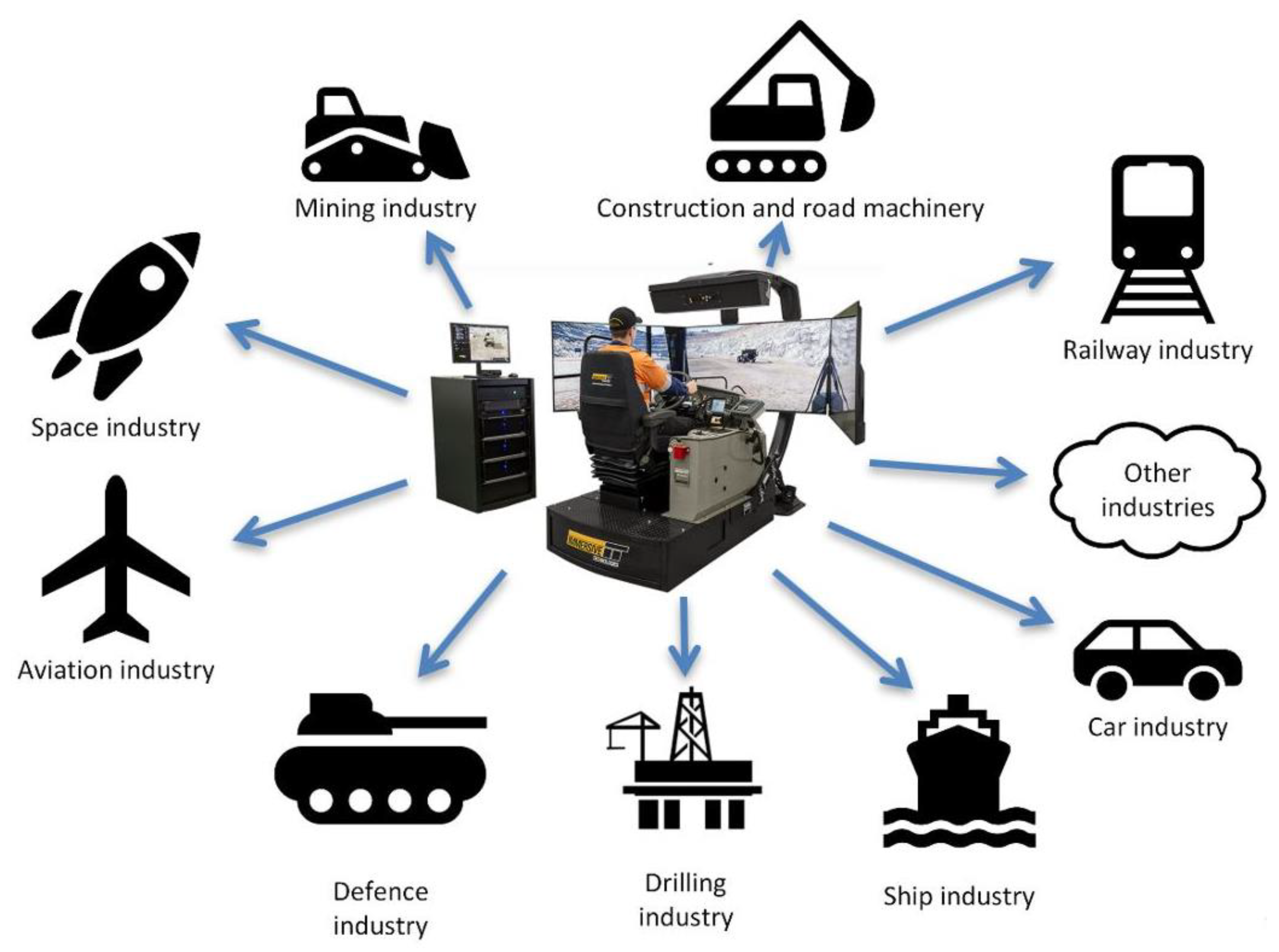
Simulators are used in various fields of human activity, mainly for machine operator training in industry, transport, and medicine. Simulator training is employed most often for machines characterized by a high degree of complexity, high cost of purchase and operation, or whose use poses a potential threat to the safety of people (e.g., passenger airplanes, ships, or mining machines operating in conditions of methane or coal dust explosion hazard). Simulators have been used for many years in leading industries where machine operators must have the highest qualifications and extensive experience (
Figure 1).
Boom-type roadheaders play a special role amongst machines used in the mining industry. They are among the most common machines used for excavation of roadways in underground mines and tunnels, as well as for the construction of underground architectural structures. Due to their high cost, roadheader use for purposes other than production (e.g., training) is limited.
Despite the relatively simple operation of the machines themselves, training an operator with the appropriate skills to operate the machines effectively is not an easy task. Results show that the operator efficiency can be impacted by the changing mining and geological conditions as well as naturally occurring hazards. Hands-on training of the operators requires access to expensive machines, their associated electricity supply, and other operating expenses, as well as an excavation face for practice. The latter can be a real working excavation during drilling (underground conditions) or training facility (e.g., in the form of a block made of equivalent materials). However, training an inexperienced operator in a working underground mine or tunnel significantly reduces the rate of progress, and may generate various types of safety issues and technical–organizational problems. Moreover, the training processes in such cases are carried out only in site-specific conditions and do not prepare the operator for other locations and situations.
Given the noted disadvantages, it is preferable to train roadheader operators using simulators, as is the case, for example, with pilots of passenger or military aircraft. Manufacturers of boom-type roadheader simulators and their products include:
Immersive Technologies (
Figure 2)—IBS SM130 roadheader;
ThoroughTec (
Figure 3)—Sandvik MH620 roadheader;
Xuzhou Hanlin Technology Co., Ltd. (
Figure 4)—SANY EBZ160 roadheader.
Simulators currently offered on the market are intended for training purposes only. They introduce tasks to machine operators in several stages, from basic construction and operation, through operation in different mining and geological conditions, to the simulation of selected emergency states and safety training.
Manuals and other articles in the literature describing existing simulators do not provide information on using them for scientific research. Importantly, it is not known what mathematical models are used for the dynamic simulations or whether they have been validated against experimental data. For example, the process of cutting the face has a significant impact on the magnitude of dynamic loads on the roadheader, which affects its effectiveness and longevity; however, the published materials on simulators lack information on issues of this kind.
Rock cutting is a basic technological operation essential to mining and tunneling. Roadheaders cut rocks mechanically with picks. These cutting heads are moved along the face at the end of a boom whose position can be set independently in the horizontal and vertical directions. In this way, the cutting heads can be moved along any path resulting from the combination of the boom movements. This flexibility makes it possible to selectively cut rocks lying in the cross-section of a drilled excavation or tunnel, and also to drill excavations of various shapes and sizes according to their intended use and the type of the roof support used. It is also possible to select the rock-cutting technology to suit the geological structure of the rock mass.
The particular configuration of the roadheader influences the manner in which the cutting operation is accomplished. Transverse cutting heads are most often moved parallel to the floor of the drilled excavation from one sidewall to the other. The rock is thus cut while making parallel cuts in the direction from the floor to the roof of the roadway or tunnel. Longitudinal cutting heads are most often moved along the heading face in a spiral motion from the center to the outside towards the sidewalls, roof, and floor, or parallel to the floor [
4,
5,
6].
Numerous experimental and simulation studies have shown that roadheader configuration and the chosen parameters of the cutting process with respect to the properties of the excavated rocks have large impacts on the efficiency, dynamic load, vibration intensity, and energy consumption of the cutting process. Many researchers have studied automatic control of cutting head movement to minimize dynamic loads and energy consumption, provide automatic navigation, and otherwise achieve more effective operation than manual control [
7,
8,
9,
10,
11,
12,
13,
14,
15,
16,
17]. These studies aimed to increase the technical potential of the machines, increase their reliability, and improve the health and safety of mining crews. The latter could be made possible by the withdrawal of crews from the heading face to a remote location. The ultimate goal is for the roadheader to become an autonomous, unmanned mining robot [
18,
19,
20,
21].
Despite intensive research and development towards roadheader robotization, these machines are still controlled manually by an operator located at the roadheader itself or a short distance away. Many factors, resulting in particular from the unpredictable environmental conditions in which roadways and tunnels are drilled, make the automation (robotization) of boom-type roadheaders extremely difficult. Apart from geological conditions, other factors include economic (high implementation costs), technical (lack of fully effective and noise-resistant automatic control algorithms), and social (caution in introducing “futuristic” technologies) considerations.
To achieve the foregoing improvements in training and technology development, each boom-type roadheader manufacturer should have virtual tools to analyze the course and evaluate the efficiency of the machine’s operation in the manual control mode. These tools can be used for training purposes, and are also useful in the work of research and development teams. For example, virtual tools can support inference from simulation and experimental tests for the development of roadheaders, optimize mining technology by minimizing dynamic loads and reducing cutting energy consumption, or provide virtual testing and evaluation of the effectiveness of automatic control algorithms. Such tasks are fulfilled by the roadheader research simulator developed in the Department of Mining Mechanization and Robotisation of the Silesian University of Technology, and are presented in this paper.
2. Characteristics of a Boom-Type Roadheader Research Simulator
A roadheader research simulator should combine the functions of a trainer with an information system enabling the collection, processing, and graphical presentation of data obtained during their recording from real cutting faces or resulting from solving implemented simulation models. The basic functional requirements for the roadheader research simulator were as follows:
Visual presentation of the cutting process at the heading face surface.
Prediction of the drive loads, efficiency, and energy consumption of mining during the rock cutting under the operator’s manual control.
Reconstruction and analysis of the course of the cutting process based on dynamic characteristics obtained from computer simulation with the use of adequate computational models.
Reconstruction and analysis of the actual mining process based on the dynamic characteristics recorded from a real cutting face or transmitted online from the roadheader monitoring system in operating or laboratory conditions, including determination of the course of the variability of the cutting efficiency and energy consumption.
Recording of the simulated cutting process to allow subsequent analysis and evaluation for presentation and training purposes.
Figure 5 shows a schematic diagram of a research simulator with a structure satisfying the above-mentioned requirements. This simulator is in the form of a distributed information technology (IT) system with networked components connected to the Internet. This architecture is conducive to ensuring the high efficiency of the entire system, as the execution of individual tasks takes place on separate workstations. This design is especially important for the Main Program, which carries out graphics calculations that require a large amount of random access memory (RAM). The entire system works in the Client–Server architecture, in which the role of the Server is played by the Main Program, which simulates the cutting geometry of the heading face. In turn, the role of the Client is played by modules (separate applications) in which computer simulations are carried out, data obtained from measurements on the real machine are processed, and data are prepared for the visualization and analysis of the cutting process. In summary, the system consists of the following components:
User/operator interface with monitors, and control systems that mimics the operator control systems of a roadheader.
A workstation with installed Server software (Main Program).
Workstations with installed Client’s software intended for the implementation of tasks related to the preparation and visualization of data, collecting data from measurements, and performing computer simulations of the mining process.
2.1. Main Program (Server) of a Roadheader Research Simulator
The Server software (i.e., Main Program) is equipped with the following:
User interface enabling operation of the entire system, initiating individual simulator functions, and manual control of the roadheader on a virtual stage.
The communication interface of the Operator Station enabling manual control of the virtual roadheader with the use of real manipulators (USB port).
A library for Client–Server network communication, supporting TCP/UDP/RAW sockets.
Module for the visualization of the cutting process of the heading face surface.
Module for video recording and playback of the course of the cutting process.
The Autodesk Inventor Professional 2022 graphics engine was used for the processing and visualization of the cutting process. Inventor software acts as an OLE Server (automation server) and provides its graphical environment and embedded objects to the simulator. The Main Program (OLE Client) thus can access and manipulate the objects of the simulator virtual scene, run the scripts registered in it, and has access to the functions of Inventor and its environment variables. This setup allows bidirectional information flow between client and server, which allows, among other things, control of the constraints that determine the positions of the roadheader’s moving parts. OLE automation mechanisms were used to implement the movement of the roadheader on a virtual stage and to generate a breakout as the cutting heads move over the heading face.
The virtual scene model built in the Autodesk Inventor environment represents the situation in the face of a excavated roadway or tunnel. This model includes:
Roadheader (in the case discussed here, the R-130 roadheader equipped with transverse cutting heads, which was developed in the design office of mining machinery manufacturer FAMUR S.A.).
A solid imitating the mined rock of the heading face.
The shape of the floor rocks and an outline of the excavation.
The boom-type roadheader model is an assembly which consists of the most important parts for operational functionality, including cutting heads, boom, turntable, and the body or chassis. These elements were given some realistic constraints. By controlling these constraints from the level of the Main Program, it is possible to move the boom horizontally and vertically, rotate the cutting heads around their axis, and move the roadheader towards the face or back. Thus, it is possible to simulate the movement of the roadheader while cutting.
Simulation of rock-cutting geometry with the cutting heads is carried out directly in the
Autodesk Inventor environment using a script written in Microsoft Visual Basic for Application (VBA). The script computes, for a given position of the boom, the operation of subtracting the solids (
Appendix A) by representing the cutting heads (
Envelope) and the solid imitating the excavated rock mass (
Rock). Since the actual structure of the roadheader allows the floor rock to be taken on, the subtraction operation also includes the solid representation of the floor rocks (
Floor) as long as the
Envelope is crossed by the
Floor. These operations are carried out for successive positions of the cutting heads on the face, corresponding to the current values of the boom deflection angles in the horizontal and vertical directions and the current position of the roadheader relative to the heading face. This script is called from the level of the Main Program (OLE Client) as a result of referring to the
InventorVBAMember property of an object of the
Inventor class and calling the
Execute() method of this class provided by the OLE Server. Access to the
oM script registered in the
Inventor object from the Pascal programming language (Embarcadero RAD Studio) in which the Simulator Main Program is written is as follows:
oP:= Inventor.VBAProjects.Item[i] ← {“ProjectDocument”}.
oC:= oP.InventorVBAComponents.Item[j] ← {“ThisDocument”}.
oM:= oC.InventorVBAMembers.Item[k] ← {“Cutting”}.
where i, j, and k are the numbers of the elements in the structure tree of the properties of the Inventor object that allows reaching the point of invocation of the script in question (the names of these elements are given in curly brackets). The object of the Inventor type is created using the CreateOleObject() method.
The volume of “excavated” rock (V) and the cross-sectional area of the cut (FSKR) necessary to calculate the efficiency of the cutting process (Q) are determined as the cutting heads move along the heading face. A mathematical engine implemented in the Autodesk Inventor environment and made available by the OLE Server was used for this purpose.
Predictions of the power necessary to cut rocks with specific mechanical properties, the drive motor current of the cutting heads, the roadheader’s power supply, the cutting energy consumption, and other important parameters of the roadheader’s operation during manual control are made based on its operational characteristics as recorded in real conditions (
Figure 6) or from computer simulations. Many simulation models have been created to study the dynamics, power prediction, cutting efficiency, and energy consumption of boom-type roadheaders. They are based, inter alia, on the use of Lagrange equations of the second type, the method of discrete elements, or artificial intelligence algorithms [
22,
23,
24,
25,
26,
27].
Prediction of the speed of movement of the cutting heads is made based on the size of the face’s cross-sectional area. The equation of the dependency trend line
v = f(FSKR) (see
Figure 6a) was used for this purpose. The cross-sectional area of the cut is calculated based on the volume of “excavated” rock and the displacement of the cutting heads in successive time intervals. The cutting efficiency (
Q) is the product of the cross-sectional area of the cut (
FSKR) and the speed of movement of the cutting heads (
v). The energy consumption
E is determined (
Figure 6b) from the energy consumption in mining based on the efficiency of this process, i.e.,
E = f(Q). The power
PC consumed by the roadheader (
Figure 6c) is found from the equation
PC = f(v). Then, a prediction is made of the roadheader supply current
IC (
Figure 6d), which includes the motor supply current in the drive of the cutting heads
IU (
Figure 6e).
2.2. Data Processing Module (Client)
The Data Processing Module installed on Workstation #2 (
Figure 5) is an application that acts as a client of the Main Program. It processes, prepares, and transmits data on the cutting process to the Server, whether obtained from a computer simulation or recorded by the measurement system of a roadheader. Data read from files or sent online are stored in the memory of Workstation #2. Data received by the module are presented graphically in the form of user-selected time courses of parameters (
Figure 7). After initiating the simulation of the mining process, the Data Processing Module sends the data systematically via the Internet to the Server (Main Program), each time requesting the Server’s confirmation of data acceptance and execution of all operations within the simulation sequence. Currently processed data are indicated in the Data Processing Module via a cursor moving along the time axis. The course of the simulated mining process in the Server application is visualized on a panel equipped with indicators reflecting the current values of the monitored process parameters and the current position of the cutting heads against the background of the outline of the excavation (similar to the Operator Station of many modern roadheaders). If necessary, it is possible to reduce the amount of simulation data by averaging the values of monitored parameters in a moving time window with a width set by the user.
2.3. Computer Simulation Module of the Dynamics of a Roadheader (Client)
The Computer Simulation Module (
Figure 5) is a separate distributed IT subsystem
SIMCUT (
Figure 8). It consists of several applications installed on dedicated Workstations (#3, #4, ...), which are Clients of the Server software (Main Program). This subsystem ensures the proper interaction of software models of the main roadheader components, the model of the cutting process, and the model of the automatic control system for the movement of the cutting heads. These models are made in various programming environments (Embarcadero RAD Studio, Matlab/Simulink, and LabView). Computational applications in which simulation models are implemented are installed at individual Workstations. They enable the following [
28]:
Simulating the cutting process at the face surface with transverse cutting heads, including:
Breakout graphics generation;
Determining parameters for cuts made by individual conical picks (depth, cutter spacing, cross-sectional area, volume of excavated material);
Determining picks’ loads from the cutting resistance for given strength parameters of the excavated rock;
Determination of time courses for loading of the cutting heads and the roadheader boom.
Simulating the dynamic loads of the inverter drive of the cutting heads during the mining process for given parameter values;
Determination of the dynamic loads and vibrations of the roadheader body as well as the load on the hydraulic boom deflecting mechanisms;
Simulating the operation of an original automatic control system for the movement of the cutting heads.
The original mathematical models used for computer simulation of the roadheader dynamics were validated based on the dynamic characteristics recorded during cutting with a real roadheader on a test stand under laboratory conditions. The working parameters of the roadheader were recorded during the cutting of the cement–sand block [
29,
30].
More information about the structure and functional features of the
SIMCUT Computer Simulation Module are described elsewhere [
28,
31].
2.4. Measurement Data Acquisition Module (Client)
The Measurement Data Acquisition Module (
Figure 5) collects digital data from the roadheader monitoring systems and routes them to the Data Processing Module. These time series data from the roadheader’s sensors are processed via a metrology program, stored in memory, and/or sent over the network to the simulator (
Figure 9).
An experimental test stand to study roadheader dynamics was built in the Technology Hall of the Faculty of Mining, Safety Engineering, and Industrial Automation of the Silesian University of Technology. An R-130 roadheader (manufactured by FAMUR S.A.) is set up to cut blocks made of rock-equivalent materials (cement–sand masses) with appropriately selected properties. The roadheader was equipped with 75 sensors enabling time series measurements of parameters characterizing its dynamic state during mining [
32]. The sensor signals were fed to a National Instruments data acquisition system equipped with measurement cards and metrological software developed in the LabView environment. The measurement data are archived in the NAS disk array (dedicated file server) and made available via Internet connections to the roadheader simulator (
Figure 9a). The Data Processing Module of the simulator prepares user-selected measurement data and sends it to the Server software (Main Program) to simulate the mining process online.
Alternatively, the simulator can use measurement data recorded during mining, or even directly from the monitoring system of a roadheader operating at the heading face underground (
Figure 9b). This allows the team to visualize the cutting process on an ongoing basis, as carried out with a roadheader operated manually or via automatic control. It is also possible to reconstruct and analyze the actual excavation process offline based on previously recorded data. This method can be used to study the effectiveness of specific technologies for cutting the heading in given operating conditions.
Figure 9.
Data Acquisition Module—recording of measured roadheader’s operating parameters: (
a) on a laboratory test stand, (
b) under operating conditions using a monitoring system (the SMOK-2 system by Somar S.A. is shown here as an example) [
33].
Figure 9.
Data Acquisition Module—recording of measured roadheader’s operating parameters: (
a) on a laboratory test stand, (
b) under operating conditions using a monitoring system (the SMOK-2 system by Somar S.A. is shown here as an example) [
33].
3. Implementation of the RH-Sim_Roadheader Research Simulator
Based on the idea described in the previous section, a software package and the associated hardware for a roadheader research simulator were developed. The simulator operation is explained in this section.
After starting the Main Program of the simulator (
RH-Sim_application) and initializing the OLE Server, the main application window displays the spatial model of the roadheader positioned next to the virtual heading face (
Figure 10). The lower part of the screen displays the version of the running OLE server (on the application status bar) and the name of the model loaded into the program (from the “iam” assembly file created in
Autodesk Inventor). The OLE Server provides the OLE Client application with an interface and the implemented model view navigation mechanisms, similarly to the
Autodesk Inventor environment. The model of the virtual scene with a specific type of roadheader is loaded from the file on application startup; however, it is possible to change the model to another one read from the appropriate CAD file.
The control panel, located on the right side of the simulator’s main screen, displays the structure of the model and the current values of the parameters determining the position of the cutting heads to the heading face, which are:
Boom deflection angle in the horizontal plane αH;
Boom deflection angle in the vertical plane αV;
Displacement of the roadheader towards the face (web of cut) ymax.
The drive parameters of the roadheader are also displayed:
Frequency of the motor supply voltage in the drive of the cutting heads f (in the case of using an inverter drive, this frequency may be changed, which translates into a change in the rotational speed of the cutting heads);
The peripheral speed of the boom swinging in the horizontal plane vH;
The peripheral speed of the boom swinging in the vertical plane vV.
At the bottom of this panel, some buttons enable manual control (with the mouse) of the boom’s movement in the horizontal and vertical direction, manual movement of the roadheader along its longitudinal axis (driving towards the face and back or sumping) and switching on/off the drive of the cutting heads. There is also the “cutting of the face” field, the selection of which causes the
oM script to be executed (see
Section 2.1). If the cutting heads cut the modeled rock surface (the cutting heads are sumped), then the script results in a breakout, imitating the cutting of the rock with the picks of the cutting head.
Users can choose how to display some model elements via the simulator application menu, including the visibility of the roadheader model and its edges, the path of the cutting heads, the transparency of the rock-solid, and the roadheader monitor display. The type of information displayed on this monitor is adapted to the method of implementation of the simulated cutting process (manual control, playback of time characteristics obtained from a computer simulation, or playback of time characteristics obtained from measurements).
A communication interface based on a universal serial bus (USB) was built to ensure the possibility of manual control of the roadheader on the virtual stage of the research simulator. The number and type of signals (digital, analog) and the communication mode (one- or two-way) between the hardware and software parts of the simulator will depend on its configuration, and corresponding to the design of the real roadheader being simulated. For testing purposes, the Operator Station was equipped with the basic control elements of the boom-type roadheader, that is (
Figure 11):
Two-way joystick (1) enabling integrated control of the boom’s movement in the horizontal and vertical plane (as is the case with real roadheaders);
One-way joystick (2) designed to control the roadheader’s driving mechanism (forward and backward travel), which makes it possible to simulate the sumping of the cutting heads into the face and reverse the roadheader;
Operating mode switch (3) of the cutting heads drive (on/off).
Communication between the control elements of the Operator Station and Workstation #1 is based on the DLP-2232M-G adapter. This module enables data transmission with the use of UART/FIFO, Bit-Bang IO, JTAG, and SPI protocols, among others [
34]. It provides 16 digital inputs/outputs (GPIO), to which keypads located in the arranged Operator Station are connected (
Figure 12).
Communication with client applications (Data Processing Module, Computer Simulation Module, and Measurement Data Acquisition Module) takes place via the Internet. Each module (Client) communicates with the Main Program (Server) using the TCP/IP data transmission protocol, through which two-way information exchange is carried out between the components (workstations) of the distributed research simulator system.
The Data Processing Module application can be run on the same Workstation on which the Simulator Server is installed, or on a remote networked computer. The module (Client) communicates with the simulator server using the TCP/IP protocol. In practice, the Client–Server communication in the discussed solution is carried out with the use of the INDY (Internet Direct) library, which supports, inter alia, TCP sockets.
After initiating the connection (“Connect” button; see
Figure 7) and transmission (“START” button), data are successively sent to the Server, where the simulation (in a graphic environment) and visualization of the rock surface mining process are performed. The simulation may include the performance of single or multiple cuts at the face of the roadway or tunnel.
The Computer Simulation Module determines the dynamic characteristics during the simulated rock mining process for a given set of physical and process parameters (rock strength, angular velocity and speed of cutting heads, web of cut, and the cut height). As described before, it is a distributed computing subsystem in which individual workstations carry out their assigned tasks using dedicated computational modeling.
Figure 13 shows the simulation algorithm for the roadheader body dynamics. This simulation covers the process of cutting the heading face surface while moving the cutting heads parallel to the floor over a given range of boom deflection angles. After reading the set of input data for the simulation, the rotational counter for the cutting heads is set to 1, and the initial value of the boom deflection angle in the plane parallel to the floor is entered. Then, a simulation of the cutting process is performed for the first rotation of the cutting heads with the given parameters. Regardless of the implementation of these calculations, the frequency of the motor supply voltage in the drive of the cutting head is determined based on the set of initial angular velocity of the head. Then, the start-up of their drive system is simulated to determine the set of initial values for the differential equations of motion in the physical model of the driving system of the cutting head and the body of a roadheader. After completing the simulation of the cutting process for the first rotation of the head, the dynamic of the roadheader is simulated. The vibration excitation is in the form of sets of discrete values obtained for each successive rotation of the cutting heads in the cutting process simulation module. The numerical calculation results are recorded as time series:
Coordinates, velocities, and accelerations of individual masses;
Dynamic loads in characteristic structural nodes of the roadheader and its drives;
Vibration acceleration in important construction nodes of the roadheader;
Magnitudes of rock-cutting process parameters.
The data are saved on a hard drive and sent to the Data Processing Module. The next rotation of the cutting head is updated based on the recorded data from the previous rotations. If the absolute value of the boom deflection angle in the horizontal direction is lower than the set maximum, simulations of the roadheader dynamics are repeated for successive revolutions of the cutting head, with corrected values of the cutting process implementation parameters.
The Measurement Data Acquisition Module provides the ability to reconstruct the real work of a roadheader while working at the face, or visualization and analysis of cutting with a roadheader on a laboratory test stand. Data collected from sensors installed in a roadheader during its normal operation, or during the implementation of a planned test program, are sent to the simulator via mining ITC networks, and/or archived in local memory. The course of the simulated cutting process can be recorded in the form of animated graphics and played with a video player built into the Main Program (
Figure 14).
4. Simulation of the Mining Process with a Roadheader—Selected Examples of Using the RH-Sim_Simulator
This section presents the possibility of using the developed research simulator for analysis of the cutting process at the face, including the dynamics of the roadheader and the energy consumption of mining. This analysis can be carried out during the simulated cutting of the face surface in the manual control mode based on the results of computer simulation of the roadheader dynamics (using validated mathematical models) or from data measured on a test stand or during mining.
4.1. Manual Control Mode
Simulated cutting of the heading face takes place during the manual control of the boom movement from the arranged Operator Station, similar to the real machine (
Figure 15a). The operator controls the movement of the roadheader using joysticks (forward movement to the face or backward movement) to deflect the boom horizontally and vertically. Electrical signals sent from the Operator Station to Workstation #1 set the constraints of the roadheader model in the Main Program of the simulator. The On/Off button on the Operator Station allows the user to toggle the rotation of the cutting heads. When the “cutting of the face” check box is selected, the solids extraction operations are performed, with results displayed by a breakout which appears in the “processed” area. The shape of the trajectory of the cutting heads’ movement depends on the method of controlling the boom’s movement by the operator. The size of the sumping of the cutting head results from the displacement of the roadheader to the face. During the simulated cutting, the trajectory of the cutting head’s movement (red line) is displayed (
Figure 15b). The monitor displays the current position of the cutting heads against the background of the excavation outline. Line indicators and digital displays give the current readings of the boom deflection angle (
αH and
αV), the roadheader’s displacement to the heading face (
ymax), and the speed of movement of the cutting heads in the horizontal and vertical directions (
vH and
vV). The dial indicators and displays located on the monitor show the values of the power consumed for cutting (
PC), the motor supply current in the cutting heads drive (
IU), the roadheader supply current and voltage (
IC,
U), the cutting efficiency, and energy consumption. In this way, the operator can observe the roadheader load during the implementation of different mining techniques and for different value process parameters. Recorded cutting cycles (
Figure 15c) can be analyzed and assessed by operators to reduce energy consumption and improve the heading face cutting efficiency during manual control of the roadheader.
4.2. Simulated Mining Mode
The Computer Simulation Module solves computational models for the given conditions of the mining process. As a result, the dynamic characteristics of the roadheader are obtained in the form of time series of the rotational and translational coordinates of the rotating masses in the drive system of the cutting heads and the separated masses which make up the roadheader’s body. On this basis, the vibrational waveforms and dynamic forces (moments of force) acting in the key construction nodes of the roadheader and its drives are determined. These waveforms are sent to the Data Processing Module, in which the selected quantities are visualized in the form of graphs (
Figure 16a). The data are then sent to the simulator server (Main Program).
Figure 16 shows the simulated performance of two cuts with a web of cut of
ymax = 0.15 m while moving the cutting heads parallel to the floor from the left sidewall of the excavation to the right sidewall (first cut) and back (second cut). The boom deflection angle in the horizontal direction
αH changed in both cases within ±30°. The mining of a rock mass consisting of two layers falling towards the left sidewall at an angle of 20° was simulated. The floorboard layer had compressive strength UCS = 20 MPa and a thickness measured along the axis of the excavation of 1.5 m, while the roof layer had compressive strength UCS = 70 MPa. The first cut was made right next to the floor (the boom deflection angle in the vertical direction
αV = −25.3°). The height of this cut had the maximum value, about 0.62 m, for a given web of cut. The second cut, towards the left sidewall, was carried out above the first cut (upper cut). Its initial height was 0.3 m. Because an automatic control algorithm was used, the cut height, angular velocity of the cutting heads, and the speed of their movement were programmatically changed by the adjuster to achieve the assumed control objectives (minimizing dynamic loads and cutting energy consumption). As a result, the cut height changed with the movement of the cutting heads, reaching 0.2 m at the left sidewall. The changes in the parameter values resulted, among others, from the changing cutting conditions caused by the change in the properties of the excavated rocks during the passage of the cutting heads through successive rock layers.
Fragments of the time waveforms are displayed via charts in the Data Processing Module window:
Top—boom deflection angles (αH and αV) and the speed of displacement of the cutting heads in the working motion (v = vH);
Middle—torque on the motor shaft in the drive of the cutting heads (M) and its angular velocity (),
Bottom—dynamic load of the boom swinging (PSO) and lifting (PSP) actuators and the acceleration of transverse vibrations of its end ().
The gray bar moving along the time axis reflects the width of the movable window in which the values of parameters sent to the Main Program are averaged. Apart from the parameters mentioned previously, the monitor displays the current value of the frequency of the motor supply voltage in the drive of the cutting heads. The Computer Simulation Module makes it possible to simulate the inverter drive of the cutting heads, which is an important element of the implemented automatic control system (described extensively elsewhere [
28]). As was the case with the manual control mode, the monitor also displays the current cutting performance and energy consumption. The registration of simulated mining enables the analysis of the dynamic load, vibration intensity in selected construction nodes of the roadheader, power demand, cutting efficiency, and energy consumption for a given set of inputs (
Figure 16b). In the case of testing the automatic control system for the movement of the cutting heads, the simulator makes it possible to evaluate the effectiveness of an automatic control system operation based on the adopted criteria functions.
4.3. Real Cutting Mode
In this mode, the simulator reconstructs the course of the mining process carried out with the use of a real roadheader working at the heading or on a laboratory test stand. The Data Processing Module presents roadheader sensor data relayed from the Measurement Data Acquisition Module graphically in the form of time series (
Figure 17a). The type of displayed parameters depends on the user. In the presented example, this visualization includes:
Top chart—boom position angles (αH and αV) and speeds of cutting heads (vH and vV);
Middle chart—roadheader electric drive parameters, including motor current in the cutting system (IU), roadheader supply current (IC), and roadheader supply voltage (U);
Bottom chart—the total power consumed by the roadheader in the cutting process (PC).
Current data sent to the simulator server (Main Program) are signaled by a moving cursor (vertical line in purple). As these data are transferred on a virtual platform showing the situation in the face of the tunnel, the cutting head moves along the actual track. A breakout is made in the face following the moving of the cutting head. The application calculates the current values of the excavated rock volume, mining efficiency, and energy consumption. Indicators arranged on the monitor show current parameters, while the position of the head is visualized against the background of the excavation.
By sending the measured data (from a real roadheader) from the entire cutting cycle to the simulator (perhaps many cycles), it is possible to trace the movement of the cutting heads, the accompanying load, and changes in the efficiency and energy consumption of cutting. The cutting technology, shapes, and sizes of individual cuts can be analyzed.
Figure 18 shows the result of such analysis. The simulator-performed cuts could be for an advance cycle of cutting the face, including all the boom and head movements. An example cycle can last nearly 3200 s or nearly 53 min. The mining was carried out in a coal seam with a compressive strength of 25 MPa and a sizable roof rock (sandy slate) with a compressive strength UCS = 68 MPa. The trajectory of the cutting head movement (red line) indicates the cutting sequence used during manual control. The cut sequence used in this process was not optimal, which resulted in a large fluctuation of the roadheader load and significant variability of the efficiency (
Q), power consumed by the roadheader (
PC), and cutting energy consumption (
E) (see
Figure 17b; this is a 60 s fragment of the course of these parameter values averaged throughout the rotation of the cutting heads
TG = 0.8 s). For manual control of the boom movement, the selection of the cutting heads’ trajectories and the cutting parameters (depth of cut, cut height, speed of the cutting heads movement) was made by the operator based on skills and experience. With little information about the cut sequence and the load on the roadheader, manual control was mainly based on the operator’s assessment of the situation in the heading and the conceived best performance of the roadheader. Recording and subsequent analysis of the performance of the roadheader in various conditions, along with the analysis of the simulator results, could be compiled into a database for the development of appropriate methods for controlling the sequence of cuts or movement of cutting heads that is best suited to offer optimal performance in a given set of conditions at the heading.
5. Summary and Conclusions
The roadheader simulator presented in this article can provide new information about the behavior of the machine and its subcomponents and the working process carried out by an operator. Validated simulation models and data processing tools help elucidate the behavior of the real machine in various operating conditions. Its construction incorporated roadheader knowledge gathered over 30 years of theoretical, simulation, and experimental research under both laboratory and operating conditions (in underground mines).
The simulator enables the study of boom-type roadheaders during the cutting process of the heading face surface in the virtual environment of an excavation operation for roadway or tunnel. The dynamic load, power demand, efficiency, and energy consumption of excavation can be calculated. The impact of technology choices, in terms of machine configuration, and the variations in the operating parameters of a roadheader and its impact on the dynamics of the roadheader can be studied. Simulator development and advancement is an ongoing process with future work involving added new functionalities, including:
Maneuvering the roadheader on the floor;
Visualization of the roadheader’s body vibrations during cutting;
Mapping in a virtual simulator environment the real shape of the heading face obtained (e.g., from scanning measurements).
The developed roadheader simulator is also a powerful tool for testing various operating strategies for automated roadheader control, which is a prerequisite for future development of autonomous roadheader robots. It also allows for the analysis and evaluation of the effectiveness of heading face cutting technologies, and can help operators select appropriate process parameters for manual control while mining in various geological conditions, as an intermediate step in transitioning from remotely operated machines to a fully autonomous operation. Similar experiences in variety of applications have shown that the automation of these machines can result in reduced maintenance requirements and ultimately higher productivity, while inherently offering improved safety by removing the operators from the heading.


