Article

Lateral Dynamic Response of Offshore Pipe Piles Considering Effect of Superstructure

1
Faculty of Engineering, Zhejiang Institute, China University of Geosciences, Wuhan 430074, China
2
Guangdong Key Laboratory of Marine Civil Engineering, Zhuhai 519082, China
3
Research Center of Coastal Urban Geotechnical Engineering, Zhejiang University, Hangzhou 310058, China
4
School of Physics and Mechanical & Electrical Engineering, Hubei University of Education, Wuhan 430205, China
5
Guangxi Key Laboratory of Disaster Prevention and Engineering Safety, Guangxi University, Nanning 530004, China
6
China Railway 16th Bureau Group No. 3 Engineering Co., Ltd., Huzhou 313000, China
*
Author to whom correspondence should be addressed.
Energies 2022, 15(18), 6759; https://doi.org/10.3390/en15186759
Submission received: 13 July 2022 / Revised: 17 August 2022 / Accepted: 8 September 2022 / Published: 15 September 2022
(This article belongs to the Special Issue Geotechnic and Geostructural Problems in Energy Engineering)

Abstract

:
The dynamic characteristics of pipe piles are of considerable importance for the dynamic foundation design of offshore wind turbines. In this study, we develop an analytical model for the lateral vibration of offshore pipe piles with consideration of the inertia effect and axial loading from the superstructure. A coupled dynamic saturated soil–pile interaction model is established based on Biot’s poroelastic theory and Euler–Bernoulli theory. The potential function, operator decomposition method, variable separation method and matrix transfer method are introduced herein to obtain the lateral force of the inner and outer soil acting on the pile shaft. Then, the analytical solution of the pile dynamic impedance in the frequency domain is derived by employing the soil–pile continuous deformation conditions and the boundary conditions of the pile. The rationality and accuracy of the presented solution have were by comparing its results with those predicted by existing solutions. The influence of superstructure, pile geometry and soil plug height on the lateral dynamic impedance and natural frequency of pipe piles was thoroughly investigated based on the theoretical model. The main findings can be summarized as: (1) The dynamic stiffness of piles will be remarkably underestimated if the inertia effect of the superstructure is not accounted for. (2) The vertical load of the superstructure is main factor affecting the natural frequency, whereas the inertia effect of the superstructure will enlarge the resonance amplitude. (3) The overall lateral dynamic impedance and first-order natural frequency of the pile increase significantly with the soil plug height.

1. Introduction

Among available renewable energy solutions, offshore wind power has become an attractive option for many countries striving to diversify their energy sources. Improving the use of wind energy can effectively reduce air pollution and alleviate the energy crisis. Compared with onshore wind farms, offshore wind turbines are more energy efficient. Recently, the offshore wind industry has been growing rapidly worldwide, especially in China. According to statistics, Chinese offshore wind power capacity newly installed in 2020 accounts for 39% of the world’s new capacity [1]. During long-term service, offshore wind turbines often withstand long-term lateral dynamic forces caused by the wind, waves, currents, blade rotation and other dynamic excitation, which may induce natural frequency variation and excessive cumulative deformation on the foundations, resulting in resonance damage or deformation failure of the offshore turbines [2]. Among the various foundation forms, monopiles are the most commonly used for offshore wind turbines, accounting for as much as 75% in practical offshore wind farms [3]. Therefore, previous studies have mainly focused on monopile foundations.
The dynamic pile–soil interaction is a critical problem with respect to the lateral dynamic characteristics of piles. Several classical theoretical methods have been developed based on various assumptions in recent decades. The dynamic beam on Winkler foundation (DBWF) model has been widely used in practical engineering owing to its calculation simplicity [4]. However this model can only represent the resistance of soil acting on the pile shaft, and the wave fluctuation effect in the soil is not taken into consideration. As a result, some scholars proposed a simplified three-dimensional continuum medium model [5,6,7] to simulate the transverse interaction along the pile shaft, although in the above-mentioned studies, the soil was regarded as single-phase soil, which may not completely suitable for offshore engineering, where the soil actually is two-phase (saturated) or three-phase (unsaturated) medium. To solve this problem, the Biot porous media theory [8,9,10,11,12,13] has been employed by many scholars to simulate the dynamic response of saturated soil or unsaturated soil [14,15,16,17].
The above research mainly focuses on solid piles. However, for offshore engineering, pipe piles are the most widely used foundation form. Huo et al. [18] investigated the static characteristics of superlong offshore steel pipe piles with a full-scale experiment. Feng et al. [19] conducted static load tests on two superlong steel pipe piles in offshore areas to investigate their ultimate bearing capacities. In the field of theoretical studies, Liu et al. [20] developed a three-dimensional analytical model for the vertical vibration of pipe piles and found that the effect of soil plug on the dynamic characteristics of pipe piles was closely related to the incident wavelength and the wall thickness. Significant progress has been achieved with respect to the dynamic pile–soil interaction problem in recent decades, whereas little attentions have been paid on the influence of superstructure on the dynamic characteristics of offshore pipe piles. Zheng et al. [21] developed an analytical model for the horizontal dynamic response of large-diameter pipe piles under combined loads based on Timoshenko beam theory. Ding et al. [22]. investigated the influence of the second-order effect of axial load on lateral dynamic characteristics of pipe piles embedded in saturated soil. An obvious limitation of existing studies is that the superstructures are often simply assumed to be a vertical concentrated load applied on the pile head, and the inertia effect of the superstructure is not taken into consideration [23]. In reality, the weight of the superstructure is not only closely associated with the vertical loading applied on the pile head, but it also remarkably affects the inertia effect under dynamic force, which may have an important influence on the dynamic characteristics of pipe piles, especially with respect to vibration-sensitive structures, such as offshore wind turbines, offshore drilling platforms, etc.
In light of this, an analytical framework for pipe piles is established to investigate the coupled effect of the inertia effect and axial loading from the superstructure on the lateral dynamic characteristics of offshore pipe piles. The pipe pile and saturated soil are simulated by the Euler–Bernoulli beam theory and Biot’s poroelastic theory, respectively. The rationality and accuracy of the presented solution were verified by comparing its results with those predicted by existing solutions. The influence of superstructure, pile radius, soil plug height and embedment depth on the lateral dynamic impedance and natural frequency of pipe piles was thoroughly investigated based on the theoretical model.

2. Governing Equation and Boundary Conditions

2.1. Models and Assumptions

The schematic of theoretical model is shown in Figure 1. The model is established in a cylindrical coordinate system with its Z-axis going downward, coinciding with the pile axis, where r , θ and z denote the radial, circumferential and longitudinal direction, respectively. The monopile-supported offshore wind turbine consists of a pile, transition piece, tower, blades and rotor. The nomenclature and parameters used herein are summarized in Nomenclature.
The following assumptions are adopted for analysis:
(1)
The vertical displacements of the soil–pile system under lateral vibrations are overlooked for mathematical simplification [24,25,26,27];
(2)
The soil is viscoelastic, isotropic and homogenous and regarded as a two-phase medium composed of pore fluid and solid skeleton;
(3)
The soil–pile system undergoes slight deformation throughout the vibration. The pile and soil are in perfect contact at the soil–pile interface;
(4)
The pile–soil interface is considered completely impervious to water, and the pile end is assumed to be a fixed boundary; and
(5)
The superstructure is simplified as a rigid platform with a concentrated mass block.

2.2. Governing Equation of the Soil

The governing equations for the saturated soil can be established as:
μ i 2 u r i + ( λ c i + μ i ) e i r μ i r 2 ( 2 u θ i θ + u r i ) α i M i ζ i r + μ i 2 u r i z 2 = ρ i u ¨ r i + ρ f i w ¨ r i
μ i 2 u θ i + ( λ c i + μ i ) e i r θ μ i r 2 ( u θ i 2 u r i θ ) α i M i ζ i r θ + μ i 2 u θ i z 2 = ρ i u ¨ θ i + ρ f i w ¨ θ i
α i M i e i r M i ζ i r = ρ f i u ¨ r i + m i w ¨ r i + b p i w ˙ r i
α i M i e i r θ M i ζ i r θ = ρ f i u ¨ θ i + m i w ¨ θ i + b p i w ˙ θ i
where λ c i = λ i + α i 2 M i , ρ i = ρ s i ( 1 κ i ) + κ i ρ f i is the mass density of the saturated soil, m i = ρ f / κ i , b p i = ρ f i g i / k d i is the viscous coupling coefficient, i = 1, 2 represents the inner and outer soil and other parameters are summarized in Nomenclature.

2.3. Governing Equation of Piles

The governing equation of the pile segment above the seabed can be simplified as:
E p I p d 4 u p 1 d z 4 + P 0 d 2 u p 1 d z 2 m p 1 ω 2 u p 1 = 0   ( H 1 z 0 )
The governing equation for the pile section embedded in the soil can be expressed as:
E p I p d 4 u p 2 d z 4 + P 0 d 2 u p 2 d z 2 m p 2 ω 2 u p 2 + f s 1 + f s 2 = 0   ( 0 z H 2 )
where f s 1 and f s 2 are the outer and inner soil resistances acting on the pile shaft, respectively; u p 1 and u p 2 are the horizontal displacements of pile segments above and below the seabed, respectively; and m p 1 and m p 2 are the corresponding mass per unit length of the pile segments.

2.4. Governing Equation of Rigid Platforms

Considering the continuity condition of bending moment and shear force between the rigid platform and pipe pile, the vibration governing equation of the rigid platform can be established as:
P ( t ) + E p I p 2 u p 1 ( H 3 , t ) z 2 = m m 2 u m t 2
J 2 θ m t 2 = E p I p [ 2 u p 1 ( H 3 , t ) z 2 + h 3 u p 1 ( H 3 , t ) z 3 ]
where m m is the total mass of the rigid platform (superstructure); u m and θ m are the horizontal displacement and section angle of the rigid platform, respectively; and H 3 = H 1 + H 2 is the total pipe pile length.

2.5. Boundary and Continuity Conditions

The boundary conditions of the soil can be expressed as:
(1)
The displacement and stress of the soil surrounding the pile approach zero at an infinite distance:
u r 2 | r = 0 , u θ 2 | r = 0 , w r 2 | r = 0 , w θ 2 | r = 0
(2)
The displacement and stress at the center of the soil plug are finite values:
u r 1 | r = 0 < , u θ 1 | r = 0 < , w r 1 | r = 0 < , w θ 1 | r = 0 <
(3)
The pile–soil interface is considered to be completely impervious to water:
w r i | r = r i = 0
(4)
The continuity conditions at the pile–soil interface are:
u r i | r = r i = u p 2 cos θ , u θ i | r = r i = u p 2 sin θ
(5)
Compared with the vertically loaded piles, the horizontally loaded piles have an efficient length beyond which further variation of pile length or boundary conditions gives rise to a negligible influence on the horizontal bearing capacity of the piles [28]. In reality, offshore piles generally exceed the efficient pile length, and varied pile-end assumptions almost have no influence on the horizontal dynamic impedance of piles. Therefore, from the viewpoint of engineering application, the pile end is assumed herein to be a fixed boundary condition for mathematical simplicity. Assuming the pile end to be a fixed support, the boundary conditions can be derived as:
u p 2 ( 0 ) = 0 , u p 2 ( 0 ) z = 0
u p 1 ( u m H θ m ) = 0 , u p 1 ( H 3 ) z θ m = 0
(6)
The continuity conditions between different pile segments are expressed as:
u p 1 ( 0 ) = u p 2 ( 0 ) ,     φ p 1 ( 0 ) = φ p 2 ( 0 )
M p 1 ( 0 ) = M p 2 ( 0 ) ,     Q p 1 ( 0 ) = Q p 2 ( 0 )

3. Solutions of Governing Equations

3.1. Solutions of Soil Governing Equations

In accordance with Helmholtz decomposition, the potential functions of φ s i , ψ s i , φ f i and ψ f i are introduced herein to decompose the governing equation of the saturated soil.
u r i = φ s i r + ψ s i r θ
u θ i = φ s i r θ ψ s i r
w r i = φ f i r + ψ f i r θ
w θ i = φ f i r θ ψ f i r
Substituting Equations (17)–(20) for Equations (1)–(4) using the separate variable method. After solving the potential functions, the displacements ( u r i , u θ i , w r i and w θ i ) of the outer soil and inner soil can be derived as:
u r i = n = 1 { D 1 i [ B ( β 1 i r ) ] + D 2 i [ B ( β 2 i r ) ] + D 3 i 1 r B ( β 3 i r ) } cos θ cos ( g n z )
u θ i = n = 1 { D 1 i 1 r B ( β 1 i r ) + D 2 i 1 r B ( β 2 i r ) + D 3 i [ B ( β 3 i r ) ] } sin θ cos ( g n z )
w r i = n = 1 { f 1 i D 1 i [ B ( β 1 i r ) ] + f 2 i D 2 i [ B ( β 2 i r ) ] + f 3 i D 3 i 1 r B ( β 3 i r ) } cos θ cos ( g n z )
w θ i = n = 1 { f 1 i D 1 i 1 r B ( β 1 i r ) + f 2 i D 2 i 1 r B ( β 2 i r ) + f 3 i D 3 i [ B ( β 3 i r ) ] } sin θ cos ( g n z )
where:
g n = ( 2 n 1 ) π 2 H 2 , n = 1 , 2 , 3
B ( β j i r ) = { K 1 ( β j i r )       i = 1 I 1 ( β j i r )         i = 2
[ K 1 ( β j 1 r ) ] = K 1 ( β j 1 r ) r , [ I 1 ( β j 2 r ) ] = I 1 ( β j 2 r ) r
β j 1 , β j 2 , f j 1 , f j 2 , j = 1, 2, 3 are the parameters related to the soil properties, as shown in Appendix A. The relationship between D j 1 and D j 2 can be determined according to the continuity conditions of the pile–soil interface; more details are presented in Appendix B.
According to the constitutive relationship with the saturated soil, the radial stress ( σ r i ) and the circumferential stress ( τ r θ i ) can be obtained as:
σ r i = λ e s i + 2 μ u r i r α p f i
τ r θ i = μ i ( u r i r θ + u θ i r u θ i r )
p f i = α M e s i M e f i
Then, the soil resistance with respect to the pile movement can be established as:
f s 1 = 0 2 π ( σ r 1 cos θ τ r θ 1 sin θ ) | r = r 1 r 1 d θ = n = 1 ζ 1 D 11 cos ( g n z )
f s 2 = 0 2 π ( σ r 2 cos θ τ r θ 2 sin θ ) | r = r 2 r 2 d θ = n = 1 ζ 2 D 12 cos ( g n z )
where:
ζ 1 = π r 1 [ ( λ 1 + 2 μ 1 + α 1 M 1 ( α 1 + f 11 ) ) β 11 2 K 1 ( β 11 r 1 ) + ( λ 1 + 2 μ 1 + α 1 M 1 ( α 1 + f 21 ) ) β 21 2 b 1 K 1 ( β 21 r 1 ) + μ 1 β 31 2 b 2 K 1 ( β 31 r 1 ) ) ]
ζ 2 = π r 2 [ ( λ 2 + 2 μ 2 + α 2 M 2 ( α 2 + f 12 ) ) β 12 2 I 1 ( β 12 r 2 ) + ( λ 2 + 2 μ 2 + α 2 M 2 ( α 2 + f 22 ) ) β 22 2 b 3 I 1 ( β 22 r 2 ) + μ 2 β 32 2 b 4 I 1 ( β 32 r 2 ) ) ]

3.2. Solutions for Governing Equations of a Saturated Soil–Pipe Pile–Rigid Platform System

The governing equation of the pile section above the soil surface can be expressed as:
E p I p d 4 u p 1 d z 4 + P 0 d 2 u p 1 d z 2 m p 1 ω 2 u p 1 = 0     ( H 1 z 0 )
The general solution to Equation (35) is:
u p 1 ( z ) = N 11 cosh λ 1 z + N 12 sinh λ 1 z + N 13 cos λ 2 z + N 14 sin λ 2 z
where: λ 1 = k 1 4 + k 1 8 + 4 k 2 4 2 , λ 2 = k 1 4 + k 1 8 + 4 k 2 4 2 , k 1 4 = P 0 E p I p , k 2 4 = m p ω 2 E p I p , N 11 , N 12 , N 13 , N 14 are the integration constants.
After obtaining the lateral displacement ( u p 1 ), according to the Euler–Bernoulli beam theory, Equation (35) can be rewritten as:
[ F 1 ( z ) ] = [ T 1 ( z ) ] [ X 1 ]     ( H 1 z 0 )
where [ F 1 ( z ) ] = [ u p 1 ( z ) φ p 1 ( z ) M p 1 ( z ) Q p 1 ( z ) ] T represents the vector of the lateral displacement, rotation angle, bending moment and shearing force, respectively; [ X 1 ] = [ N 11 N 12 N 13 N 14 ] T indicates the vector of the integration constants in Equation (36); and [ T 1 ( z ) ] satisfies the following vector:
[ T 1 ( z ) ] = [ cosh ( λ 1 z ) sinh ( λ 1 z ) cos ( λ 2 z ) sin ( λ 2 z ) λ 1 sinh ( λ 1 z ) λ 1 cosh ( λ 1 z ) λ 2 sin ( λ 2 z ) λ 2 cos ( λ 2 z ) λ 1 2 cosh ( λ 1 z ) E p I p λ 1 2 sinh ( λ 1 z ) E p I p λ 2 2 cos ( λ 2 z ) E p I p λ 2 2 sin ( λ 2 z ) E p I p λ 1 3 sinh ( λ 1 z ) E p I p λ 1 3 cosh ( λ 1 z ) E p I p λ 2 3 sin ( λ 2 z ) E p I p λ 2 3 cos ( λ 2 z ) E p I p ]
Then, the relationship between [ F 1 ( 0 ) ] and [ F 1 ( H 1 ) ] can be obtained according to Equation (37) as:
[ F 1 ( H 1 ) ] = [ f 1 ] [ F 1 ( 0 ) ]
where [ f 1 ] = [ T 1 ( H 1 ) ] [ T 1 ( 0 ) ] 1 .
According to Equations (33) and (34), the horizontal governing equation for the pile segment embedded in the soil can be derived as:
E p I p d 4 u p 2 d z 4 + P 0 d 2 u p 2 d z 2 m p 2 ω 2 u p 2 + n = 1 ζ 1 D 11 cos ( g n z ) + n = 1 ζ 2 D 12 cos ( g n z ) = 0       ( 0 < z H 2 )
The method for solving Equation (40) is presented in Appendix C. The principle for determining lateral displacement ( u p 2 ) is similar to Equation (37) and can be expressed as:
[ F 2 ( z ) ] = [ T 2 ( z ) ] [ X 2 ]       ( 0 < z H 2 )
where [ F 2 ( z ) ] = [ u p 2 ( z )     φ p 2 ( z )     M p 2 ( z )     Q p 2 ( z ) ] T represents the vector of the lateral displacement, rotation angle, bending moment and shearing force, respectively. The nomenclature of [ X 2 ] and [ T 2 ( z ) ] are shown in Appendix C.
Then, the relationship between [ F 2 ( H 2 ) ] and [ F 2 ( 0 ) ] can be obtained according to Equation (41) as:
[ F 2 ( 0 ) ] = [ f 2 ] [ F 2 ( H 2 ) ]
where [ f 2 ] = [ T 2 ( 0 ) ] [ T 2 ( H 2 ) ] 1 .
According to Equations (17)–(20):
[ F 2 ( 0 ) ] = [ F 1 ( 0 ) ]
The relationship between [ F 2 ( H 2 ) ] and [ F 1 ( H 1 ) ] can be obtained according to Equations (36), (39) and (40) as:
[ F 1 ( H 1 ) ] = [ T ] [ F 2 ( H 2 ) ]
where [ T ] = [ f 2 ] [ f 1 ] .
Assuming that the bottom of the pipe pile is completely fixed, the pile bottom displacement and turning angle are zero. According to the boundary conditions:
[ u 1 p ( H 1 ) φ 2 p ( H 1 ) M 2 p ( H 1 ) Q 2 p ( H 1 ) ] = [ T 11 T 12 T 13 T 14 T 21 T 22 T 23 T 24 T 31 T 32 T 33 T 34 T 41 T 42 T 43 T 44 ] [ 0 0 M 1 p ( H 2 ) Q 1 p ( H 2 ) ]
Because the rigid bearing also performs simple harmonic motion, the term e i ω t on can be eliminated on both sides of the equation. The arithmetic can be derived as:
m m ω 2 u m π 4 E p ( r 1 4 r 2 4 ) 3 u p 1 u 3 = P 0
J ω θ m π 4 E p ( r 1 4 r 2 4 ) [ 2 u p 1 ( H 1 ) z 2 + H 3 u p 1 ( H 1 ) z 3 ] = 0
Equation (16) can be derived as:
[ J ω 2 T 23 T 33 H T 43 ] M p 1 ( H 2 ) + [ J ω 2 T 24 T 34 H T 44 ] Q p 1 ( H 2 ) = 0
[ m m ω 2 T 13 + m m ω 2 H T 23 T 43 ] M p 1 ( H 2 ) + [ m m ω 2 T 14 + m m ω 2 H T 24 T 44 ] Q p 1 ( H 2 ) = P 0
According to Equations (43) and (44):
M p 1 ( H 2 ) = P 0 T b , Q p 1 ( H 2 ) = T a T b P 0
where: T a = J ω 2 T 23 T 33 H T 43 T 34 + H T 44 J ω 2 T 24 ,
T b = m m ω 2 T 13 + m m ω 2 H T 23 T 43 + T a m m ω 2 T 14 + T a m m ω 2 H T 24 T a T 44
In the calculation of a single pile, its dynamic response can be expressed in terms of the dynamic response of the top of the pile. Therefore, lateral dynamic impedance ( K H ) for the pile can be deduced as:
K H = Q p ( H 1 ) u p ( H 1 )
In the pile-soil system, pile lateral dynamic impedance can be defined as its real and imaginary parts, with the real part indicating the lateral dynamic stiffness and the imaginary part expressing the lateral dynamic damping. The dimensionless lateral stiffness and damping values are presented as follows:
K h = r 1 3 E p I p Re ( K h ) , C h = r 1 3 E p I p Im ( K h )

4. Validation

Comparison with Existing Theoretical Models

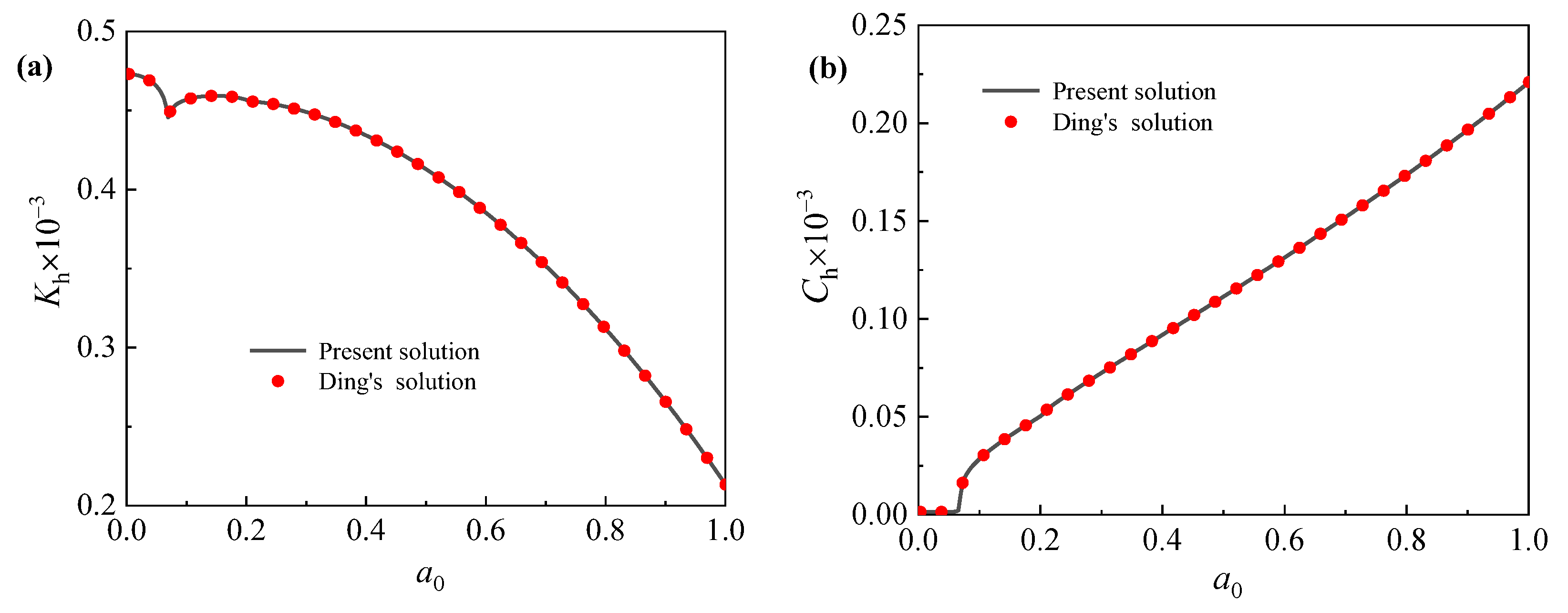
Ding et al. [22] developed an analytical model to investigate the influence of the second-order effect of axial load on lateral dynamic characteristics of pipe piles embedded in saturated soil; the superstructure was simplified as axial load, and its inertia effect was not taken into consideration. By assuming an unchanged vertical load and setting the inertia effect of the superstructure to zero, the present solution can be degenerated into Ding’s solution. To verify the rationality and accuracy of the present model, the lateral dynamic impedance of the degenerated solution presented herein is compared with that predicted by Ding’s solution. The parameters used herein are set the same as those used in Ding’s study, and their values are summarized in Table 1.
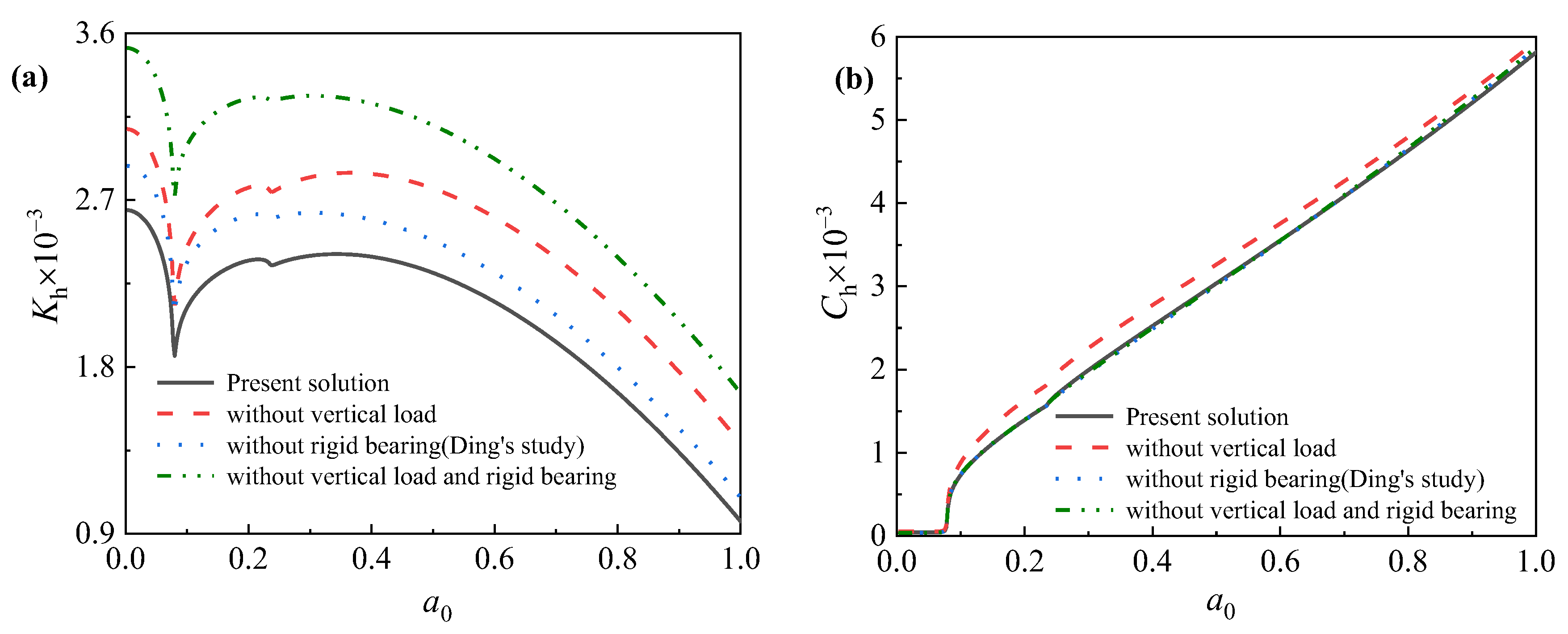
Figure 2 shows comparisons of the lateral dynamic impedance of the pile predicted by the degenerated solution of the present model with that of Ding’s solution. When the inertia effect of the superstructure is set to zero, both the lateral dynamic stiffness and the damping obtained using the proposed degenerated solution completely coincide with those calculated with Ding’s solution. To further validate the rationality and accuracy of the present model, its dynamic impedance is compared with the results of three existing classical theoretical models. Four cases are introduced herein. In case 1 (present model), both the vertical loading and inertia effect of the superstructure are taken into consideration. In case 2 (degenerated solution of the present model), only the inertia effect is considered, and the vertical loading is ignored. Case 3 (Ding’s model) only considers the vertical load, and the inertia effect is not accounted for. Case 4 (single-pile model) does not consider the superstructure.
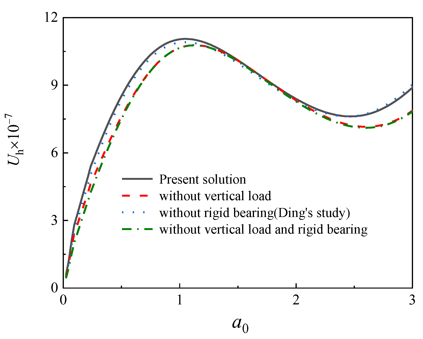
As depicted in Figure 3, the existence of vertical load leads to a decrease in both the dynamic stiffness and the dynamic damping, in accordance with Ding’s conclusions. Figure 3 shows that the inertia effect of the superstructure has a remarkable influence on the dynamic stiffness of the piles. If the inertia effect of the superstructure is not accounted for, the dynamic stiffness of the piles will be considerably underestimated, whereas the influence of the inertia effect on the dynamic damping of piles is generally small and can be basically neglected. Figure 4 displays the influence of the superstructure on the displacement spectrum of piles, of which the natural frequency is of considerable importance for the dynamic foundation of offshore wind turbines. Figure 4 shows that the existence of a superstructure leads to a decrease in the natural frequency of piles. A comparison of case 1 and case 3 indicates that the vertical load of the superstructure is the main factor affecting the natural frequency, whereas the inertia effect of the superstructure increases the resonance amplitude. Hence, the rationality and accuracy of the present theoretical model are confirmed based on above analysis.

5. Parametric Analysis and Discussion

In this section, the major factors affecting the dynamic characteristics of offshore piles are systematically investigated based on the theoretical model. Because in this study, we mainly focus on pipe piles as support for offshore wind turbines, the parameters used herein are based on a practical offshore wind application reported by K. V’azquez et al. [29]. Based on an application case of offshore steel pipe piles in practical engineering, unless otherwise specified, the parameters used herein the same as those presented in Table 2.

5.1. Influence of Rigid Platform Height on Lateral Dynamic Characteristics of Offshore Pipe Piles

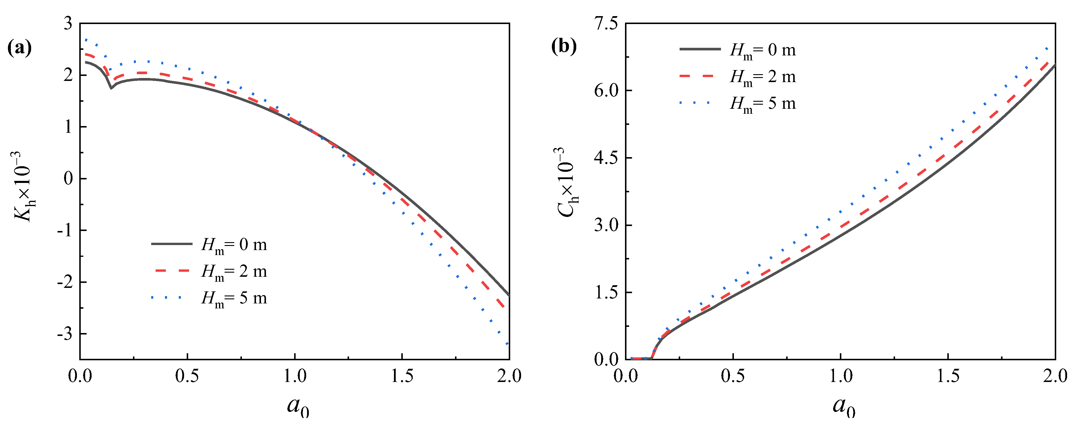
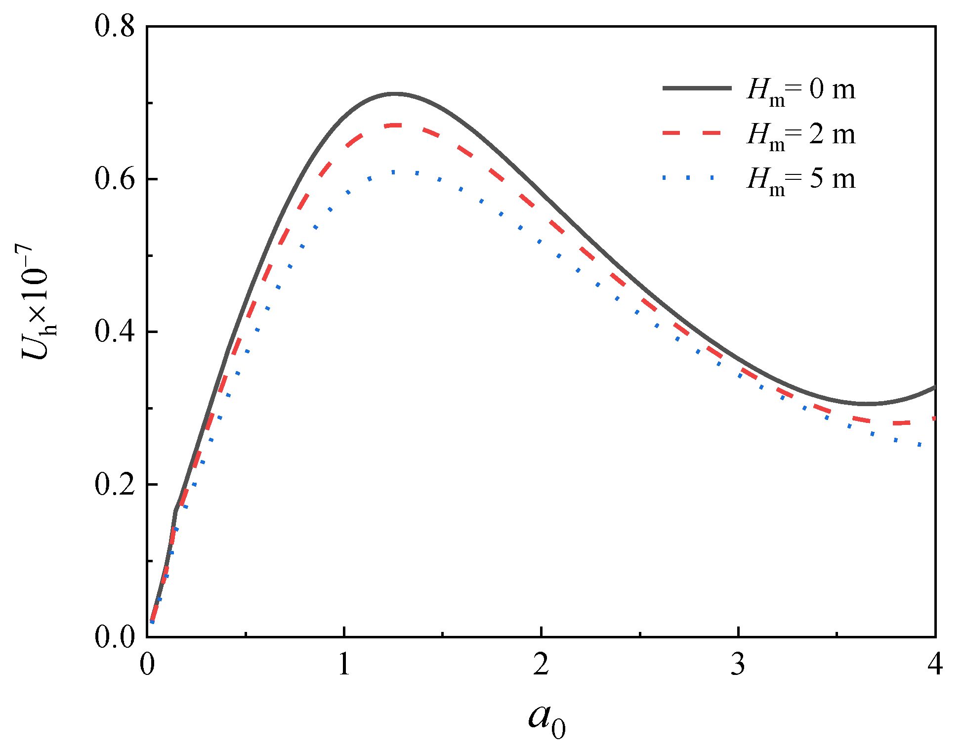
As shown in Equations (7) and (8), the total mass, along with the inertia effect of the superstructure, is assumed to be concentrated on the rigid platform connecting the pipe pile and upper tower tube. The influence of the rigid platform height on the dynamic charactericstics of offshore pipe piles is determined first. a 0 = 2 ω r 1 / v s represents the dimensionless frequency, and u h is the displacement amplitude of the offshore pipe piles. Three rigid platform heights are considered, i.e., H m = 0, 2 m and 5 m; and the total mass of the superstructure is set to m m = 2 × 10 5   kg . Figure 5 illustrates the effect of the rigid platform height on the lateral dynamic impedance of the pile head. As shown in Figure 5a, the dynamic stiffness of the pile initially increases with the platform height; nevertheless, when the dimensionless frequency exceeds a threshold value, the dynamic stiffness begins to decrease with increased platform height. Figure 5 also shows that the dynamic damping of the pile remains basically unchanged, regardless of the variation in the platform height in the low-frequency range. However, with increased frequency, the dynamic damping of the pile head increases significantly with the platform height, and this phenomenon becomes much more pronounced in the high-frequency range, indicating that the energy dissipation capacity of the offshore piles is enhanced with increased platform height. Figure 6 depicts the influence of the platform height on the displacement spectrum of the pipe pile. The resonant amplitude of the pipe pile decreases obviously with increased platform height, whereas the first-order natural frequency of the pipe pile remains basically unchanged. Therefore an increase in the rigid platform height can significantly improve the ability of the offshore wind turbine foundation to resist horizontal loadings.

5.2. Influence of Superstruture Mass on Lateral Dynamic Characteristics of Offshore Pipe Piles

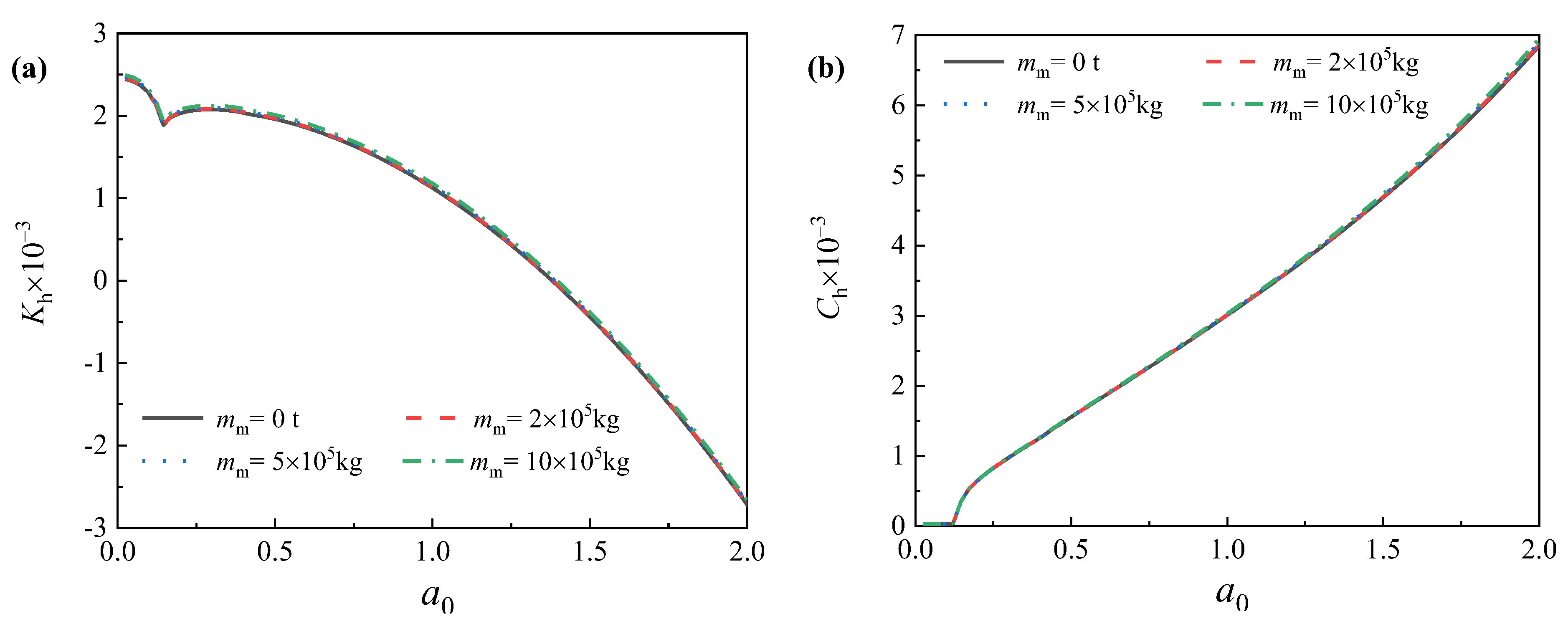
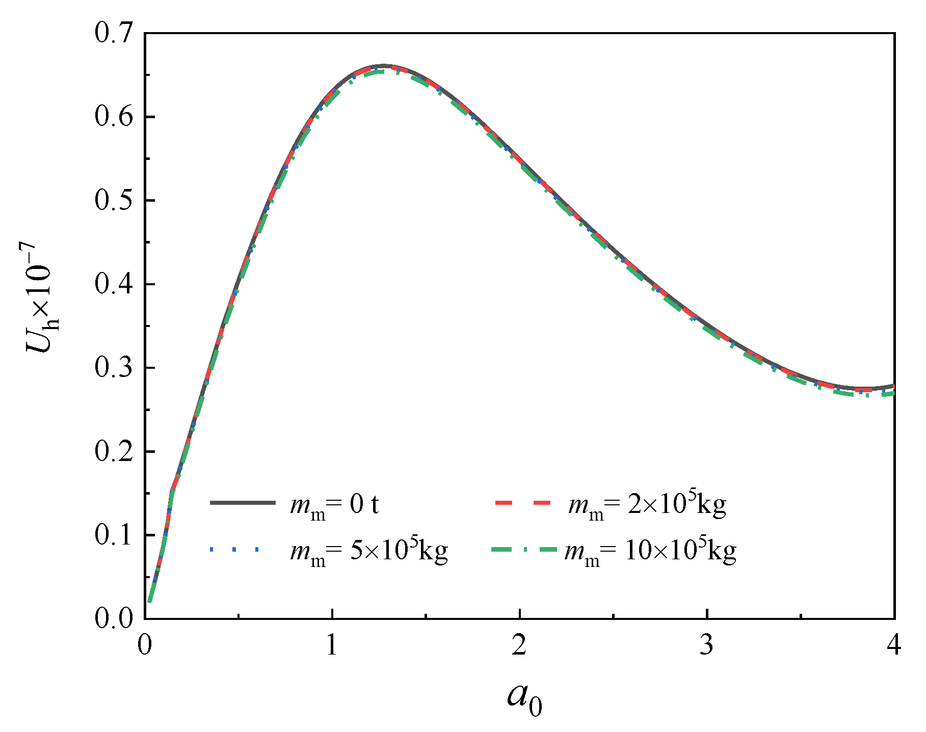
Figure 7 illustrates the effect of superstructure mass on the lateral dynamic impedance of offshore pipe piles, where the total superstructure mass is set to m m = 0, 2 × 10⁵ kg, 5 × 10⁵ kg and 10 × 105 kg. Variation in the superstructure mass exerts a negligible influence on the dynamic impedance of the pile head in the low-frequency range, whereas with increased frequency, both the dynamic stiffness and damping of the pile head increase with the superstructure mass. Figure 8 shows that the first-order resonant amplitude of the pipe pile decreases with increased superstructure mass; however, the significant variation in the natural frequency is not visually obvious. In summary, the dynamic stability of the pipe piles increases gradually with increased total superstructure mass. In comparison to rigid bearing mass, both the dynamic stiffness and damping of the pile head are more sensitive to variation in the rigid platform height.

5.3. Influence of Soil Plug Height on Lateral Dynamic Characteristics of Offshore Pipe Piles

Open-ended pipe piles are the most widely used type of foundation for offshore structures. During the installation of open-ended pipe piles, part of the soil underneath the pile tip is pushed into the pile, forming a soil column called a “soil plug” [30,31]. The influence of the soil plug on the vertical bearing capacity and dynamic characteristics of pipe piles has been thoroughly investigated in recent decades [32,33,34,35,36,37,38,39]. However, little attention has been paid to the contribution of the soil plug to the lateral dynamic response of pipe piles. The soil plug plays an important role in the dynamic foundation design, especially in the dynamic sensitive structures, such as offshore wind turbines, offshore drilling platforms and offshore bridges. An obvious shortcoming of existing studies is that the soil plug height is often assumed to be equal to the pile embedment length, without considering the soil plug effect. The soil plug state is dependent on the soil condition, pile geometry and construction method. For most engineering cases, the soil plug height is lower than the pile embedment length, and under soft clay soil conditions, the soil plug top may even exceed the seabed level. In general, it is not common for the soil plug height be equal to the pile embedment length [40,41,42,43]. Therefore, the major goal of this section is to answer the question as to how extensively the soil plug height can affect the lateral dynamic characteristics of offshore pipe piles.
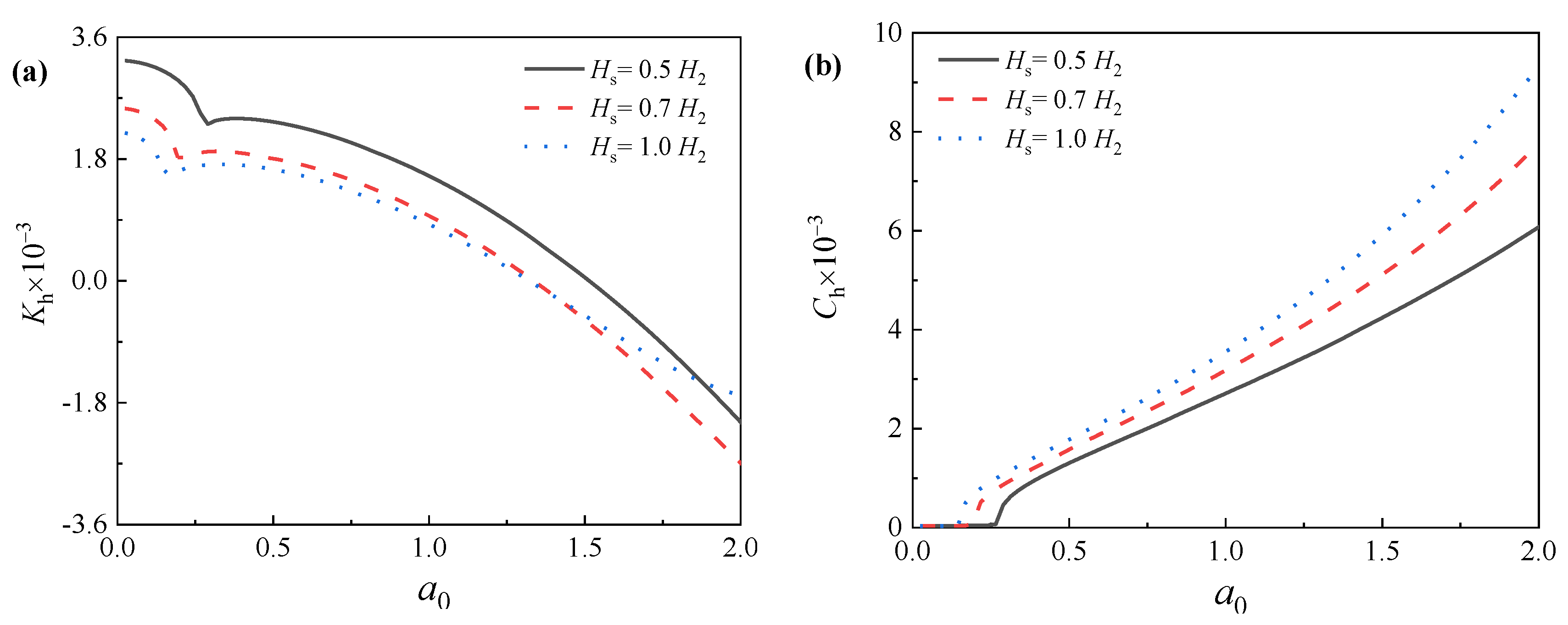
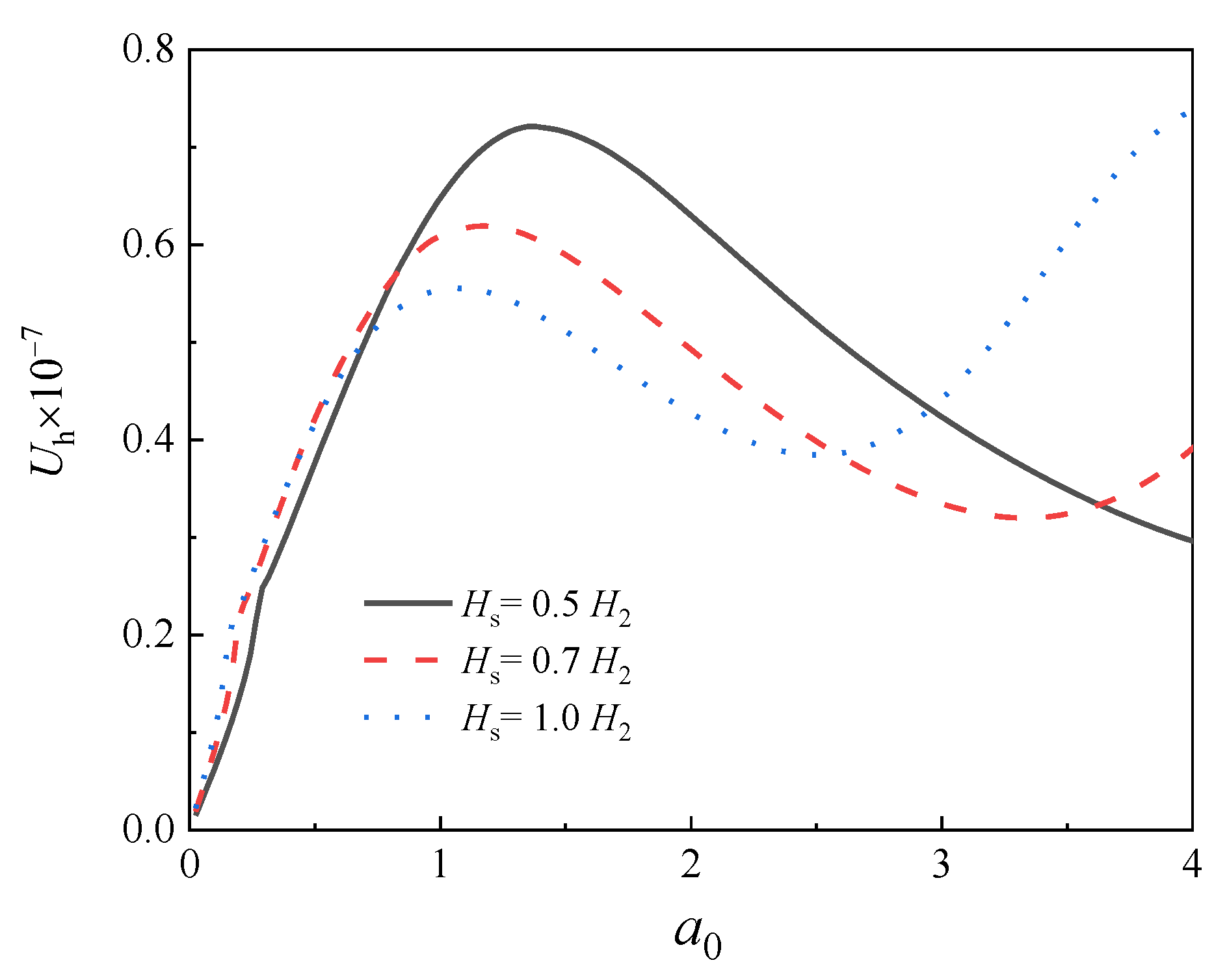
In this section, the total mass of the superstructure and the height of the rigid platform are set to m m = 2 × 10 5   kg and H m = 2.5   m , respectively. The soil plug height is assumed to be Hs = 0.5 H2, 0.7 H2, 1.0 H2, where H2 represents the embedment length of the pile. Figure 8 shows that the influence of the soil plug height on the lateral dynamic impedance of the offshore pipe piles is highly dependent on the frequency. In the low-frequency range, the dynamic stiffness and dynamic damping decrease and increase, respectively with increased soil plug height. When the frequency increases beyond a threshold value, e.g., a0 = 0.2, the dynamic impedance of the pile exhibits an inverse tendency with respect to the soil plug height. Figure 9 shows the influence of the soil plug height on the displacement spectrum of the pipe piles. The first-order natural frequency, which is a direct reflection of the dynamic impedance of the pile, is of considerable importance for the dynamic foundation design of offshore wind turbine. Figure 10 shows that the first-order natural frequency of the pile increases remarkably with the soil plug height, indicating that the overall lateral dynamic impedance of the pile also increases with the soil plug height. Therefore, in order to avoid resonance damage of offshore wind turbines in a complex marine environment and improve the calculation accuracy, it is necessary to consider the contribution of the soil plug to the lateral dynamic characteristics of offshore pipe piles.

5.4. Influence of Pile Radius on Lateral Dynamic Characteristics of Offshore Pipe Piles

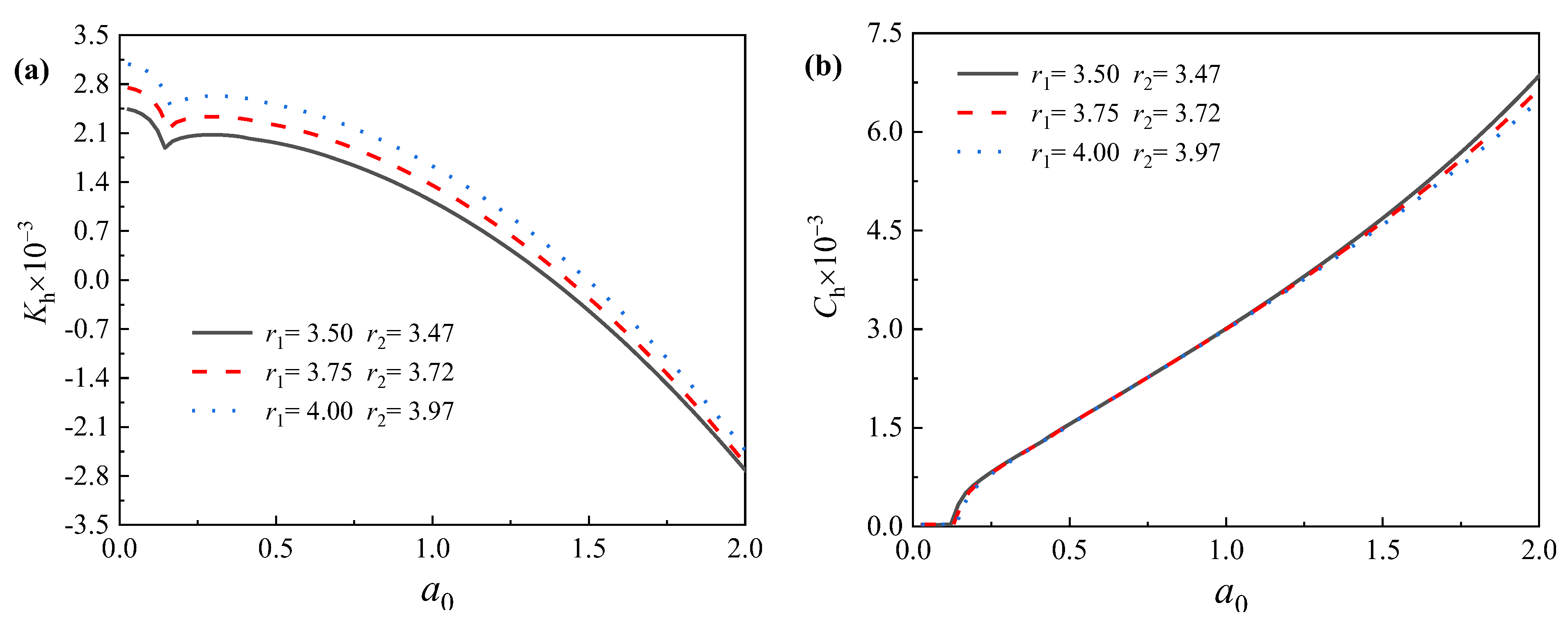
Figure 11 illustrates the influence of the pile radius on the later dynamic impedance of the pile, where the thickness of the pile remains unchanged (bp = 30 mm), and the radius is set to r1 = 3.5 m, 3.75 m and 4.0 m.
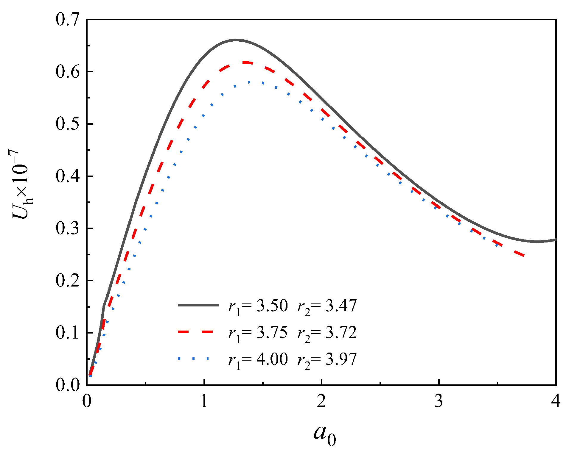
As shown in Figure 11, despite some fluctuations, the dynamic stiffness and the dynamic damping of the pile generally increase with the pile radius within the frequency range of most engineering applications. In the physical sense, an increase in the pile radius cannot only enhance its ability to resist deformation but also increase the energy dissipation ability of the pile–soil system. Figure 12 shows the influence of the pile radius on the displacement spectrum of the pile. In accordance with the dynamic impedance curve, Figure 12 shows that the first-order natural frequency of the pipe pile also increases with the pile radius. Therefore, an increase in the pile radius can significantly improve the lateral dynamic stability of offshore pipe piles.

5.5. Influence of Embedment Ratio on the Lateral Dynamic Characteristics of Offshore Pipe Piles

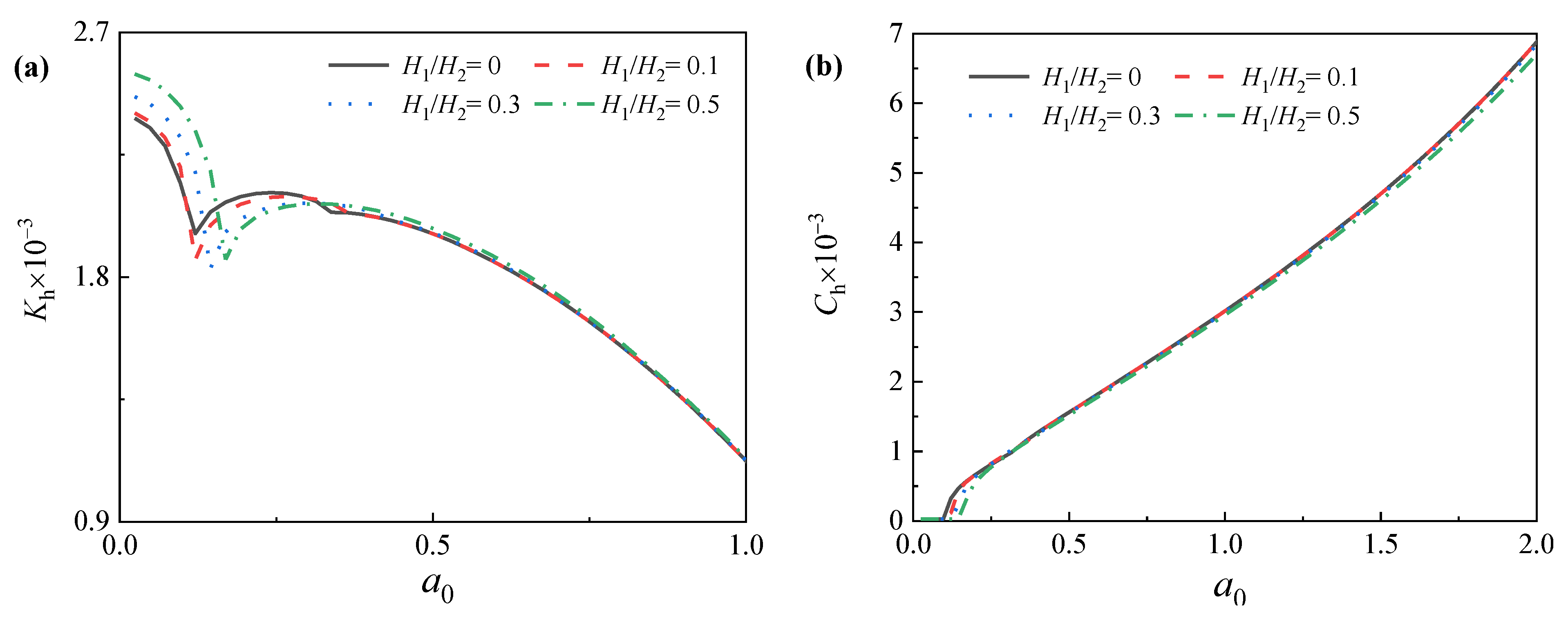
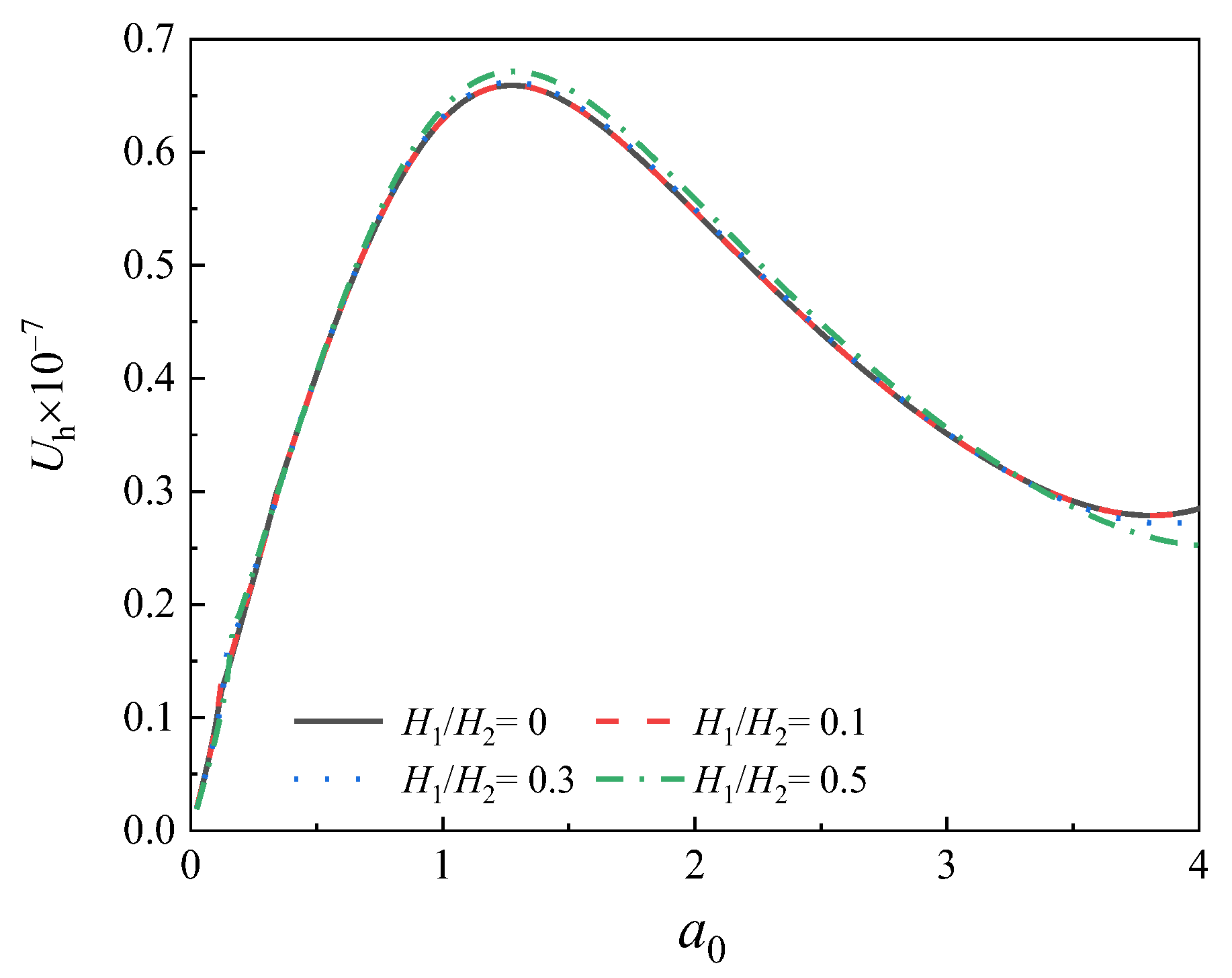
In the present investigation, we mainly concentrate on fully embedded piles, whereas partially embedded pipe piles are more consistent with actual engineering applications. The embedment ratio, which is defined as the ratio of the pile length above the soil (H1) to the embedment pile length (H2), is an important factor with respect to dynamic foundation design of offshore wind turbines. Figure 13 displays the influence of the embedment ratio on the lateral dynamic impedance of the piles, where the total pile length is kept constant, and the embedment ratio is set to H1/H2 = 0, 0.1, 0.3 and 0.5. As shown in Figure 13, the embedment ratio has relatively minimal influence on the lateral dynamic stiffness of the pile in the low-frequency range. With increased frequency, the dynamic stiffness of the pile increases with the embedment ratio. Compared with dynamic stiffness, the influence of the embedment ratio on the dynamic damping of the pile is much smaller. Figure 14 presents the influence of the embedment ratio on the displacement spectrum of the pile. With increased embedment ratio, the first-order natural frequency of the pile also increases. In summary, the embedment ratio has remarkable impact on the natural frequency and the stiffness factors. The influence of the embedment ratio the damping factors is considered negligible.

6. Conclusions

The dynamic characteristics of pipe piles are of considerable importance for the dynamic foundation design of offshore wind turbines. In this study an analytical model is proposed for the lateral vibration of offshore pipe piles, considering the inertia effect and axial loading of the superstructure. The rationality and accuracy of the present solution were verified by comparing its results with those predicted by existing solutions. The influence of superstructure, pile radius, soil plug height and embedment depth on the dynamic characteristics of pipe piles was systematically investigated based on the theoretical solutions. The main findings can be summarized as follows:
(1)
If the inertia effect of the superstructure is not accounted for, the dynamic stiffness of piles will be remarkably underestimated, whereas the dynamic damping of piles remains basically unchanged;
(2)
The vertical load of the superstructure is the main factor affecting the natural frequency, whereas the inertia effect of the superstructure will result in increased resonance amplitude;
(3)
The first-order natural frequency of the pile increases significantly with the soil plug height, indicating that the overall lateral dynamic impedance of the pile also increases with the soil plug height;
(4)
Despite some fluctuations, the dynamic stiffness, as well as the dynamic damping of the pile, generally increases with the pile radius within the frequency range of most engineering applications.

Author Contributions

H.L.: Formal analysis, Investigation, Writing—Original Draft. J.L.: Conceptualization, Resources. X.Y.: Mathematical modeling, Writing—Review & Editing. L.C.: Methodology Supervision. W.W.: Methodology Supervision, Writing—Review & Editing. M.W.: Methodology Supervision. M.J.: Methodology Supervision, Funding acquisition. C.G.: Funding acquisition, Project administration. All authors have read and agreed to the published version of the manuscript.

Funding

This research is supported by the National Natural Science Foundation of China (Grant Nos. 52108355, 52178371, 51878634, 52108347), the Outstanding Youth Project of Natural Science Foundation of Zhejiang Province (Grant No. LR21E080005), and the Exploring Youth Project of Zhejiang Natural Science Foundation (Grant No. LQ22E080010). The Fundamental Research Founds for National University, China University of Geosciences (Wuhan) (Grant No. CUGGC09), the Construction Research Founds of Department of Housing and Urban-Rural Development of Zhejiang Province (Grant No. 2021K256), the China Postdoctoral Science Foundation Funded Project (Grant No. 2020M673093), the Foundation of Guangdong Key Laboratory of Oceanic Civil Engineering (No. LMCE202003) and the Systematic Project of Guangxi Key Laboratory of Disaster Prevention and Structural Safety (Grant Nos. 2021ZDK001, 2021ZDK011) are also acknowledged.

Conflicts of Interest

The authors declare no conflict of interest.

Nomenclature

ω Load frequency
iImaginary unit
m m Mass of superstructure
A p Cross-sectional area
P p Vertical load ( P p = m m g / A p )
r 1 Outer radius
r 2 Inner radius
E p I p Bending rigidity
H 1 Pile length above the soil
H 2 Length of pile section embedded in the soil
2 H m Height of rigid bearing
P ( t ) = P 0 e i ω t Horizontal hamonic load
P 0 Load magnitude
J Inertia of rotation around the center-of-mass axis
u r i Radial displacements of solid matrix
w r i Radial displacements of pore fluid
u θ i Circumferential displacements of solid matrix
w θ i Circumferential displacements of pore fluid
2 Laplace operator
e i Dilatational strain of the saturated soil
G i Shear modulus
ξ i Damping ratio
λ i Complex lamb constants
μ i Complex lamb constants ( μ i = G i ( 1 + 2 ξ i i ) )
α i Biot compression coefficients
M i Biot compression coefficients
ρ s i Solid skeleton
ρ f i Pore fluid
κ i Porosity of the soil
k d i Darcy permeability coefficient of the soil

Appendix A

The variables appearing in Equations (21)–(24) are defined as:
β 1 i 2 = d 1 i + d 1 i 2 4 d 2 i 2
β 2 i 2 = d 1 i d 1 i 2 4 d 2 i 2
β 3 i 2 = ρ i ω 2 ( m i ω 2 b p i ω i ) ρ f 2 ω 4 μ i ( m i ω 2 b p i ω i )
d 1 i = ( λ c i + 2 μ i ) ( m i ω 2 b p i ω i ) + 2 α i M i ρ f i ω 2 ( λ i + 2 μ i ) M i ρ i ω 2 μ i g n 2 λ i + 2 μ i
d 2 i = ρ i ω 2 ( m i ω 2 b p i ω i ) ρ f i 2 ω 4 ( λ i + 2 μ i ) M i
f 1 i = α i M i β 1 i 2 + ρ f i ω 2 M i β 1 i 2 + m i ω 2 b p i ω i
f 2 i = α i M i β 2 i 2 + ρ f i ω 2 M i β 2 i 2 + m i ω 2 b p i ω i
f 3 i = ρ f i ω m i ω b p i i

Appendix B

Given the continuity condition at the pile–soil interface (Equation (12)):
n = 1 { D 11 [ K 1 ( β 11 r 1 ) ] + D 21 [ K 1 ( β 21 r 1 ) ] + D 31 1 r 1 K 1 ( β 31 r 1 ) } cos ( g n z ) = u p 2
n = 1 { D 11 1 r 1 K 1 ( β 11 r 1 ) D 21 1 r 1 K 1 ( β 21 r 1 ) D 31 [ K 1 ( β 31 r 1 ) ] } cos ( g n z ) = u p 2
n = 1 { f 11 D 11 [ K 1 ( β 11 r 1 ) ] + f 21 D 21 [ K 1 ( β 21 r 1 ) ] + f 31 D 31 1 r 1 K 1 ( β 31 r 1 ) } cos ( g n z ) = 0
Given the following definitions:
γ 11 = [ K 1 ( β 11 r 1 ) ] 1 r 1 K 1 ( β 11 r 1 ) ,   γ 21 = [ K 1 ( β 21 r 1 ) ] 1 r 1 K 1 ( β 21 r 1 ) ,   γ 31 = [ K 1 ( β 31 r 1 ) ] 1 r 1 K 1 ( β 31 r 1 ) ,   γ 41 = f 11 [ K 1 ( β 11 r 1 ) ] ,   γ 51 = f 21 [ K 1 ( β 21 r 1 ) ] ,   γ 61 = f 31 1 r 1 K 1 ( β 31 r 1 )
According to Equations (A9)–(A11):
D 21 = b 1 D 11
D 31 = b 2 D 11
where b 1 = γ 11 γ 61 γ 31 γ 41 γ 31 γ 51 γ 21 γ 61 and b 2 = γ 21 γ 41 γ 11 γ 51 γ 31 γ 51 γ 21 γ 61 .
Given the continuity condition at the pile–soil interface (Equation (12)):
n = 1 { D 12 [ I 1 ( β 12 r 2 ) ] + D 22 [ I 1 ( β 22 r 2 ) ] + D 32 1 r 2 I 1 ( β 32 r 2 ) } cos ( g n z ) = u p 2
n = 1 { D 12 1 r 2 I 1 ( β 12 r 2 ) D 22 1 r 2 I 1 ( β 22 r 2 ) D 32 [ I 1 ( β 32 r 2 ) ] } cos ( g n z ) = u p 2
n = 1 { f 12 D 12 [ I 1 ( β 12 r 2 ) ] + f 22 D 22 [ I 1 ( β 22 r 2 ) ] + f 32 D 32 1 r 2 K 1 ( β 32 r 2 ) } cos ( g n z ) = 0
Defining
γ 12 = [ I 1 ( β 12 r 2 ) ] 1 r 2 I 1 ( β 12 r 2 ) ,   γ 22 = [ K 1 ( β 22 r 2 ) ] 1 r 2 K 1 ( β 22 r 2 ) ,   γ 32 = [ K 1 ( β 32 r 2 ) ] 1 r 2 K 1 ( β 32 r 2 ) ,   γ 42 = f 12 [ K 1 ( β 12 r 2 ) ] , γ 52 = f 22 [ K 1 ( β 22 r 2 ) ] ,   γ 62 = f 32 1 r 2 K 1 ( β 32 r 2 )
According to Equations (A14), (A15) and (A16):
D 22 = b 3 D 12
D 32 = b 4 D 12
where b 3 = γ 12 γ 62 γ 32 γ 42 γ 32 γ 52 γ 22 γ 62 and b 4 = γ 22 γ 42 γ 12 γ 52 γ 32 γ 52 γ 22 γ 62 .

Appendix C

The general solution for Equation (40) can be obtain as:
u p 2 ( z ) = N 21 cosh λ 1 z + N 22 sinh λ 1 z + N 23 cos λ 2 z + N 24 sin λ 2 z n = 1 ( ξ 1 D 11 + ξ 2 D 12 ) cos ( g n z )
where ξ 1 = ζ 1 E p I p ( g n 4 k 1 4 g n 2 k 2 4 ) , ξ 2 = ζ 2 E p I p ( g n 4 k 1 4 g n 2 k 2 4 ) and N 21 , N 22 , N 23 , N 24 are the integration constants.
According to the continuity condition of the pile–soil system shown as Equation (10):
N 21 cosh λ 1 z + N 22 sinh λ 1 z + N 23 cos λ 2 z + N 24 sin λ 2 z n = 1 ( ξ 1 D 11 + ξ 2 D 12 ) cos ( g n z ) = n = 1 ζ 1 D 11 cos ( g n z )
N 21 cosh λ 1 z + N 22 sinh λ 1 z + N 23 cos λ 2 z + N 24 sin λ 2 z n = 1 ( ξ 1 D 11 + ξ 2 D 12 ) cos ( g n z ) = n = 1 ζ 2 D 12 cos ( g n z )
Therefore,
D 12 = ζ 1 D 11 ζ 2
The integration constants (D11 and D22) can be obtained as:
D 11 = ζ 2 ( χ 1 N 21 + χ 2 N 22 + χ 3 N 23 + χ 4 N 24 )
D 21 = ζ 1 ( χ 1 N 21 + χ 2 N 22 + χ 3 N 23 + χ 4 N 24 )
where,
χ 1 = 2 0 H 2 cosh ( λ 1 z ) cos ( h n z ) d z ( ζ 1 ζ 2 + ξ 1 ζ 2 + ξ 2 ζ 1 ) H 2
χ 2 = 2 0 H 2 sinh ( λ 1 z ) cos ( h n z ) d z ( ζ 1 ζ 2 + ξ 1 ζ 2 + ξ 2 ζ 1 ) H 2
χ 3 = 2 0 H 2 cos ( λ 2 z ) cos ( h n z ) d z ( ζ 1 ζ 2 + ξ 1 ζ 2 + ξ 2 ζ 1 ) H 2
χ 4 = 2 0 H 2 sin ( λ 2 z ) cos ( h n z ) d z ( ζ 1 ζ 2 + ξ 1 ζ 2 + ξ 2 ζ 1 ) H 2
Finally, the horizontal displacement of pipe pile can be expressed as follows:
u p 2 ( z ) = N 21 [ cosh λ 1 z n = 1 χ 1 ϑ n cos ( g n z ) ] + N 22 [ sinh λ 1 z n = 1 χ 2 ϑ n cos ( g n z ) ] + N 23 [ cos λ 2 z n = 1 χ 3 ϑ n cos ( g n z ) ] + N 24 [ sin λ 2 z n = 1 χ 4 ϑ n cos ( g n z ) ]
where ϑ n = ζ 1 ξ 2 + ζ 2 ξ 1 .
After determining the lateral displacement ( u p 2 ), these quantities can be expressed as:
[ F 2 ( z ) ] = [ T 2 ( z ) ] [ X 2 ]       ( 0 < z H 2 )
where [ F 2 ( z ) ] = [ u p 2 ( z )     ϕ p 2 ( z )     M p 2 ( z )     Q p 2 ( z ) ] T is the vector of the lateral displacement, rotation angle, bending moment and shearing force, [ X 2 ] = [ N 21   N 22   N 23   N 24 ] T is the vector of the integration constants in Equation (A19) and [ T 2 ( z ) ] satisfies the following vector:
[ T 2 ( z ) ] = [ cosh ( λ 1 z ) n = 1 χ 1 ϑ n cos ( g n z ) sinh ( λ 1 z ) n = 1 χ 2 ϑ n cos ( g n z ) cos ( λ 2 z ) n = 1 χ 3 ϑ n cos ( g n z ) sin ( λ 2 z ) n = 1 χ 4 ϑ n cos ( g n z ) λ 1 sinh ( λ 1 z ) + n = 1 χ 1 ϑ n g n sin ( g n z ) λ 1 cosh ( λ 1 z ) + n = 1 χ 2 ϑ n g n sin ( g n z ) λ 2 sin ( λ 2 z ) + n = 1 χ 3 ϑ n g n sin ( g n z ) λ 2 cos ( λ 2 z ) + n = 1 χ 4 ϑ n g n sin ( g n z ) E p I p ( λ 1 2 cosh ( λ 1 z ) + n = 1 χ 1 ϑ n g n 2 cos ( g n z ) ) E p I p ( λ 1 2 sinh ( λ 1 z ) + n = 1 χ 2 ϑ n g n 2 cos ( g n z ) ) E p I p ( λ 2 2 cos ( λ 2 z ) + n = 1 χ 3 ϑ n g n 2 cos ( g n z ) ) E p I p ( λ 2 2 sin ( λ 2 z ) + n = 1 χ 4 ϑ n g n 2 cos ( g n z ) ) E p I p ( λ 1 3 sinh ( λ 1 z ) n = 1 χ 1 ϑ n g n 3 sin ( g n z ) ) E p I p ( λ 1 3 cosh ( λ 1 z ) n = 1 χ 2 ϑ n g n 3 sin ( g n z ) ) E p I p ( λ 2 3 sin ( λ 2 z ) n = 1 χ 3 ϑ n g n 3 sin ( g n z ) ) E p I p ( λ 2 3 cos ( λ 2 z ) n = 1 χ 4 ϑ n g n 3 sin ( g n z ) ) ]

References

  1. Carter, J.M.F. North Hoyle offshore wind farm: Design and build. Energy 2007, 160, 21–29. [Google Scholar] [CrossRef]
  2. Gavin, K.; Igoe, D.; Doherty, P. Piles for offshore wind turbines: A state-of-art review. Proc. Inst. Civ. Eng. Geotech. Eng. 2011, 164, 245–256. [Google Scholar] [CrossRef]
  3. Nogami, T. Soil-pile interaction model for earthquake response analysis of offshore pile foundations. In Proceedings of the International Conference on Recent Advances in Geotechnical Earthquake Engineering & Soil Dynamics, St. Louis, MO, USA, 11–15 March 1991; Volume 3, pp. 2133–2137. [Google Scholar]
  4. Nogami, T.; Novak, M. Resistance of soil to a horizontally vibrating pile. Earthq. Eng. Struct. Dyn. 1977, 5, 249–261. [Google Scholar] [CrossRef]
  5. Zheng, C.J.; Liu, H.L.; Ding, X.M.; Fu, Q. Horizontal vibration of a large-diameter pipe pile in viscoelastic soil. Math. Probl. Eng. 2013, 2013, 269493. [Google Scholar] [CrossRef]
  6. Luan, L.B.; Ding, X.M.; Zhou, W.; Zheng, C.; Qu, L. Horizontal dynamic response of a large-diameter pipe pile considering the second-order effect of axial force. Earthq. Eng. Eng. Vib. 2018, 17, 567–579. [Google Scholar] [CrossRef]
  7. Ding, X.M.; Zheng, C.J.; Liu, H.L.; Kouretzis, G. Resistance of inner soil to the horizontal vibration of pipe piles. J. Eng. Mech. 2017, 143, 6017015. [Google Scholar] [CrossRef]
  8. Biot, M.A. General theory of three-dimensional consolidation. J. Appl. Phys. 1941, 12, 155–164. [Google Scholar] [CrossRef]
  9. Biot, M.A. General solutions of the equations of elasticity and consolidation for a porous material. J. Appl. Mech. 1956, 23, 91–96. [Google Scholar] [CrossRef]
  10. Biot, M.A. Theory of deformation of a porous viscoelastic anisotropic solid. J. Appl. Phys. 1956, 27, 459–467. [Google Scholar] [CrossRef]
  11. Ishihara, K. Approximate forms of wave equations for water-saturated porous materials and related dynamic modulus. Soils Found. 1970, 10, 10–38. [Google Scholar] [CrossRef] [Green Version]
  12. Ishihara, K. Propagation of compressional waves in a saturated soil. In Proceedings of the International Symposium of Wave Propagation and Dynamic Properties of Earth Materials, Albuquerque, NM, USA, 23–25 August 1967; University of New Mexico Press: Albuquerque, NM, USA, 1968; pp. 195–206. [Google Scholar]
  13. Zienkiewicz, O.C.; Shiomi, T. Dynamic behaviour of saturated porous media; the generalized Biot formulation and its numerical solution. Int. J. Numer. Anal. Methods Geomech. 1984, 8, 71–96. [Google Scholar] [CrossRef]
  14. Hu, A.F.; Fu, P.; Xia, C.Q.; Xie, K.H. Lateral dynamic response of a partially embedded pile subjected to combined loads in saturated soil. Mar. Georesources Geotechnol. 2017, 35, 788–798. [Google Scholar] [CrossRef]
  15. Zheng, C.; Liu, H.; Ding, X. Lateral dynamic response of a pipe pile in saturated soil layer. Int. J. Numer. Anal. Methods Geomech. 2016, 40, 159–184. [Google Scholar] [CrossRef]
  16. Cui, C.; Meng, K.; Xu, C.; Liang, Z.; Li, H.; Pei, H. Analytical solution for longitudinal vibration of a floating pile in saturated porous media based on a fictitious saturated soil pile model. Comput. Geotech. 2021, 131, 103942. [Google Scholar] [CrossRef]
  17. Wu, W.; Yang, Z.; Liu, X.; Zhang, Y.; Liu, H.; El Naggar, M.H.; Xu, M.; Mei, G. Horizontal dynamic response of pile in unsaturated soil considering its construction disturbance effect. Ocean Eng. 2022, 245, 110483. [Google Scholar] [CrossRef]
  18. Huo, S.; Chao, Y.; Dai, G.; Gong, W. Field Test Research of Inclined Large-Scale Steel Pipe Pile Foundation for Offshore Wind Farms. J. Coast. Res. 2015, 73, 132–138. [Google Scholar] [CrossRef]
  19. Feng, S.J.; Lu, S.F.; Shi, Z.M. Field Investigations of Two Super-long Steel Pipe Piles in Offshore Areas. Mar. Georesources Geotechnol. 2015, 34, 559–570. [Google Scholar] [CrossRef]
  20. Liu, H.; Wu, W.; Jiang, G.; El Naggar, M.H.; Mei, G.; Liang, R. Influence of soil plug effect on the vertical dynamic response of large diameter pipe piles. Ocean Eng. 2018, 157, 13–25. [Google Scholar] [CrossRef]
  21. Zheng, C.; Luan, L.; Qin, H.; Zhou, H. Horizontal Dynamic Response of a Combined Loaded Large-Diameter Pipe Pile Simulated by the Timoshenko Beam Theory. Int. J. Struct. Stab. Dyn. 2019, 20, 2071003. [Google Scholar] [CrossRef]
  22. Ding, X.; Luan, L.; Zheng, C.; Zhou, W. Influence of the second-order effect of axial load on lateral dynamic response of a pipe pile in saturated soil layer. Soil Dyn. Earthq. Eng. 2017, 103, 86–94. [Google Scholar] [CrossRef]
  23. Chen, L.; Yang, X.; Li, L.; Wu, W.; El Naggar, M.H.; Wang, K.; Chen, J. Numerical Analysis of the Deformation Performance of Monopile under Wave and Current Load. Energies 2020, 13, 6431. [Google Scholar] [CrossRef]
  24. Novak, M.; Nogami, T.; Aboul-Ella, F. Dynamic soil reactions for plane strain case. J. Eng. Mech. Div. 1978, 104, 953–959. [Google Scholar]
  25. Militano, G.; Rajapakse, R.K.N.D. Dynamic response of a pile in a multi-layered soil to transient torsional and axial loading. Geotechnique 1999, 49, 91–109. [Google Scholar] [CrossRef]
  26. Gupta, B.K.; Dipanjan, B. Timoshenko Beam Theory-Based Dynamic Analysis of Laterally Loaded Piles in Multilayered Viscoelastic Soil. J. Eng. Mech. 2018, 144, 04018091. [Google Scholar] [CrossRef]
  27. Zhang, Y.; El Naggar, M.H.; Wu, W.; Wang, Z.; Yang, X.; Jiang, G. Dynamic torsional impedance of large-diameter pipe pile for offshore engineering: 3D analytical solution. Appl. Math. Model. 2022, 111, 664–680. [Google Scholar] [CrossRef]
  28. Zhang, M.; Shang, W.; Wang, X.H.; Chen, F.Y. Lateral dynamic analysis of single pile in partially saturated soil. Eur. J. Environ. Civ. Eng. 2019, 23, 1156–1177. [Google Scholar] [CrossRef]
  29. Vázquez, K.; Rodríguez, R.R.; Esteban, M.D. Inventory proposal for monopiles in offshore wind farms. Ocean Eng. 2022, 247, 110741. [Google Scholar] [CrossRef]
  30. Paikowsky, S.G. A Static Evaluation of Soil Plug Behavior with Application to the Pile Plugging Problem. Ph.D. Thesis, Massachusetts Institute of Technology, Cambridge, MA, USA, 1989. [Google Scholar]
  31. Randolph, M.F.; Leong, E.C.; Houlsby, G.T. One-dimensional analysis of soil plugs in pipe piles. Geotechnique 1991, 41, 587–598. [Google Scholar] [CrossRef]
  32. Feng, Y.; Yang, J. Base capacity of open-ended steel pipe piles in sand. J. Geotech. Geoenviron. Eng. 2012, 138, 1116–1128. [Google Scholar]
  33. Lehane, B.M.; Schneider, J.A.; Xu, X. The UWA-05 method for prediction of axial capacity of driven piles in sand. In Proceedings of the International Symposium on Frontiers in Offshore Geotechnics (ISFOG), Perth, Australia, 19–21 September 2005; Taylor & Francis: London, UK, 2005; pp. 683–689. [Google Scholar]
  34. Liu, H.; Jiang, G.; El Naggar, M.H.; Wu, W.; Mei, G.; Liang, R. Influence of soil plug effect on the torsional dynamic response of a pipe pile. J. Sound Vib. 2017, 410, 231–248. [Google Scholar] [CrossRef]
  35. Wu, W.; El Naggar, M.H.; Abdlrahem, M.; Mei, G.; Wang, K. A new interaction model for the vertical dynamic response of pipe piles considering soil plug effect. Can. Geotech. J. 2017, 54, 987–1001. [Google Scholar] [CrossRef]
  36. Liu, H.; Wu, W.; Jiang, G.; El Naggar, M.H.; Mei, G.; Liang, R. Benefits from using two receivers for the interpretation of low-strain integrity tests on pipe piles. Can. Geotech. J. 2019, 56, 1433–1447. [Google Scholar] [CrossRef] [Green Version]
  37. Liu, H.; Wu, W.; Ni, X.; Yang, X.; Jiang, G.; El Naggar, M.H.; Liang, R. Influence of soil mass on the vertical dynamic characteristics of pipe piles. Comput. Geotech. 2020, 126, 103730. [Google Scholar] [CrossRef]
  38. Li, L.; Zheng, M.; Liu, X.; Wu, W.; Liu, H.; El Naggar, M.H.; Jiang, G. Numerical analysis of the cyclic loading behavior of monopile and hybrid pile foundation. Comput. Geotech. 2022, 144, 104635. [Google Scholar] [CrossRef]
  39. Li, L.; Liu, X.; Liu, H.; Wu, W.; Lehane, B.M.; Jiang, G.; Xu, M. Experimental and numerical study on the static lateral performance of monopile and hybrid pile foundation. Ocean Eng. 2022, 255, 111461. [Google Scholar] [CrossRef]
  40. Henke, S.; Grabe, J. Field measurements regarding the influence of the installation method on soil plugging in tubular piles. Acta Geotech. 2012, 8, 335–352. [Google Scholar] [CrossRef]
  41. Henke, S.; Bienen, B. Investigation of the influence of the installation method on the soil plugging behaviour of a tubular pile. In Proceedings of the 8th International Conference on Physical Modelling in Geotechnics, Perth, Australia, 14–17 January 2014. [Google Scholar]
  42. Lehane, B.M.; Gavin, K.G. Base Resistance of Jacked Pipe Piles in Sand. J. Geotech. Geoenviron. Eng. 2001, 127, 473–480. [Google Scholar] [CrossRef]
  43. Chow, Y.K.; Phoon, K.K.; Chow, W.F.; Wong, K.Y. Low strain integrity testing of piles: Three-dimensional effects. J. Geotech. Geoenviron. Eng. 2003, 129, 1057–1062. [Google Scholar] [CrossRef]
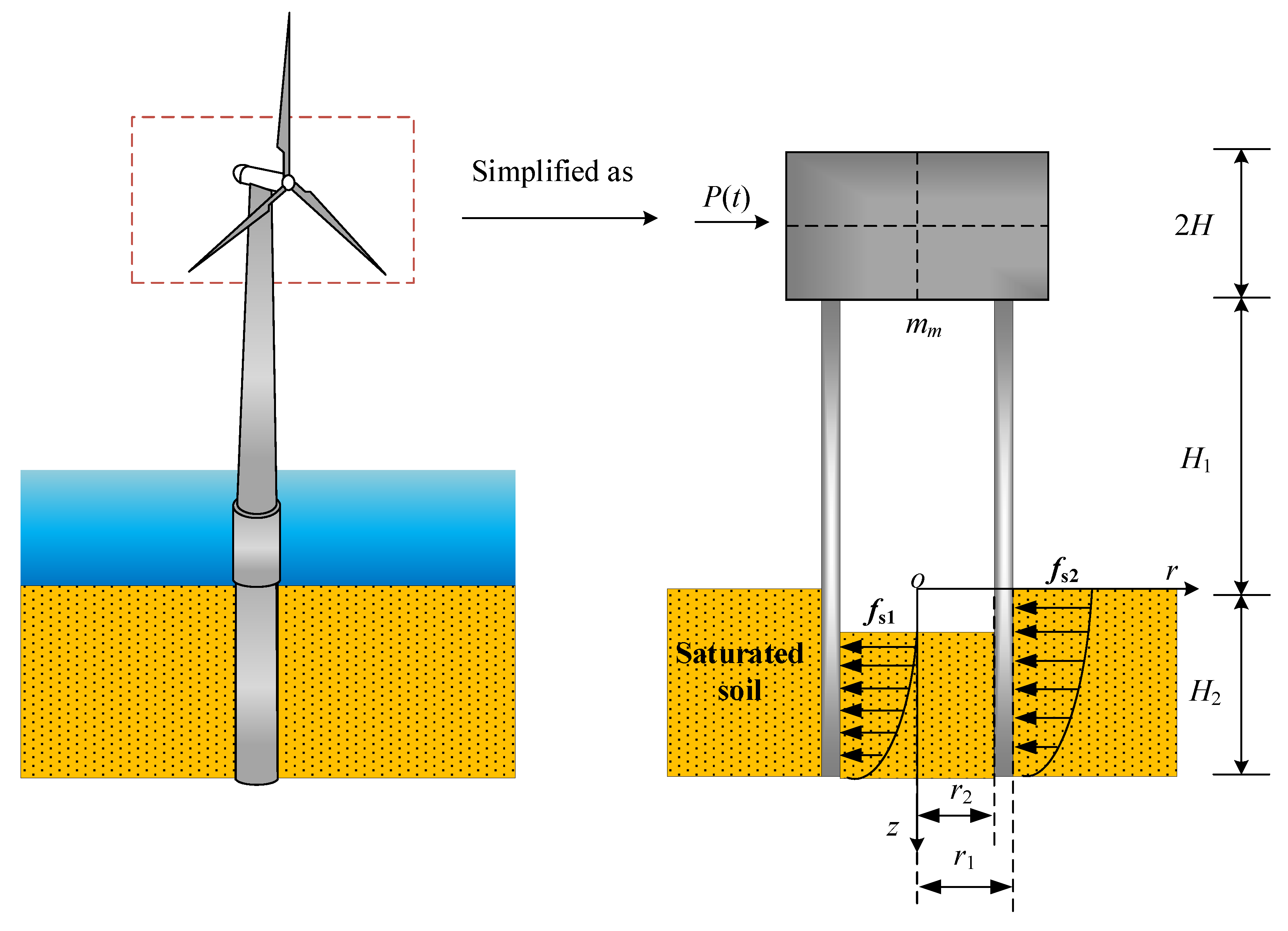
Figure 1. Analytical model of a saturated soil–pipe, pile–superstructure system.
Energies 15 06759 g001
Figure 2. Comparisons of lateral dynamic impedance predicted by the degenerated solution of the present model and Ding’s solution: (a) stiffness; (b) damping.
Energies 15 06759 g002
Figure 3. Comparisons of lateral dynamic impedance predicted by different theoretical models: (a) stiffness; (b) damping.
Energies 15 06759 g003
Figure 4. Comparison of displacement spectrum of piles predicted by different theoretical models.
Energies 15 06759 g004
Figure 5. Influence of rigid platform height on the lateral dynamic impedance of offshore pipe piles: (a) stiffness; (b) damping.
Energies 15 06759 g005
Figure 6. Influence of rigid bearing height on the displacement spectrum of pipe piles.
Energies 15 06759 g006
Figure 7. Influence of rigid bearing mass on the lateral dynamic impedance of offshore pipe piles: (a) stiffness; (b) damping.
Energies 15 06759 g007
Figure 8. Influence of rigid bearing mass on the displacement spectrum of pipe piles.
Energies 15 06759 g008
Figure 9. Influence of soil plug height on the lateral dynamic impedance of offshore pipe piles: (a) stiffness; (b) damping.
Energies 15 06759 g009
Figure 10. Influence of soil plug height on the displacement spectrum of pipe piles.
Energies 15 06759 g010
Figure 11. Influence of pile radius on the lateral dynamic impedance of offshore pipe piles: (a) stiffness; (b) damping.
Energies 15 06759 g011
Figure 12. Influence of pile radius on the displacement spectrum of pipe pile.
Energies 15 06759 g012
Figure 13. Influence of embedment ratio on the lateral dynamic impedance of offshore pipe piles: (a) stiffness; (b) damping.
Energies 15 06759 g013
Figure 14. Influence of embedment ratio on the displacement spectrum of pipe piles.
Energies 15 06759 g014
Table 1. Parameters of degenerated model.
H2
(m)
r1
(m)
r2
(m)
Ep
(GPa)
Es (MPa)kd
(m/s)
rp
(kg/m3)
rf
(kg/m3)
M (GPa) v α ζ
100.50.38252.010−6250010001.00.30.990.05
Table 2. Parameters of the practical engineering case.
H 1
(m)
H 2
(m)
r 1
(m)
r 2
(m)
E p
(GPa)
E s
(MPa)
k d
(m/s)
ρ p
(kg/m3)
ρ s
(kg/m3)
M
(GPa)
v s α ζ β s a 0
10403.53.472201.010−6778020004.90.40.990.010.050.5
Publisher’s Note: MDPI stays neutral with regard to jurisdictional claims in published maps and institutional affiliations.