Faulty Operation of Coils’ and Humidifier Valves in a Typical Air-Handling Unit: Experimental Impact Assessment of Indoor Comfort and Patterns of Operating Parameters under Mediterranean Climatic Conditions
Abstract
:1. Introduction
1.1. Research Gaps
1.2. Novelty, Goals and Structure of the Paper
- post-heating coil valve stuck at 100% (always open);
- post-heating coil valve stuck at 0% (always closed);
- cooling coil valve stuck at 100% (always open);
- cooling coil valve stuck at 0% (always closed);
- humidifier valve stuck at 0% (always closed).
- highlighting the difference between AHU field faulty operation and nominal fault-free performance;
- assessing the impacts in terms of thermal/hygrometric comfort of the selected faults based on the comparison of experimental data gathered under normal and faulty scenarios;
- recognizing the AHU faults characterized by the most significant effects in order to identify the most important priorities of future maintenance programs;
- facilitating and supporting the development of data-driven rule-based AFDD methods thanks to the identification of the most impacting key-operating parameters by evaluating the symptoms’ occurrence probability;
- collecting and curating a reliable faulty and fault-free field dataset of a typical AHU operating under Italian weather conditions to be publicly shared with the related research community.
2. Description of the Experimental Set-Up
2.1. HVAC System
2.2. Integrated Test Room
2.3. Sensors and Measurement Uncertainty
2.4. Control Logics of the AHU
- the desired targets of both indoor air temperature (TSP,Room) and relative humidity (RHSP,Room) to be achieved inside the integrated test room;
- the deadbands DBT and DBRH associated with TSP,Room and RHSP,Room, respectively;
- the velocity of both the return air fan (OLRAF) and the supply air fan (OLSAF) between 0% and 100%;
- the opening percentages of the return air damper (OPDRA), the outside air damper (OPDOA) and the exhaust air damper (OPDEA) between 0% and 100% (where 100% means that the damper is fully open);
- the activation/deactivation of the static heat-recovery system by setting the opening percentage of the heat-recovery system damper (OPDHRS).
3. Methodology: Design of Experiments
- fault 1: the post-heating coil valve always kept closed (stuck at 0%) during the faulty tests FS1 and FW1;
- fault 2: the post-heating coil valve always kept fully open (stuck at 100%) during the faulty tests FS2 and FW2;
- fault 3: the cooling coil valve always kept closed (stuck at 0%) during the faulty tests FS3 and FW3;
- fault 4: the cooling coil valve always kept fully open (stuck at 100%) during the faulty tests FS4 and FW4;
- fault 5: the humidifier valve always kept closed (stuck at 0%) during the faulty tests FS5 and FW5.
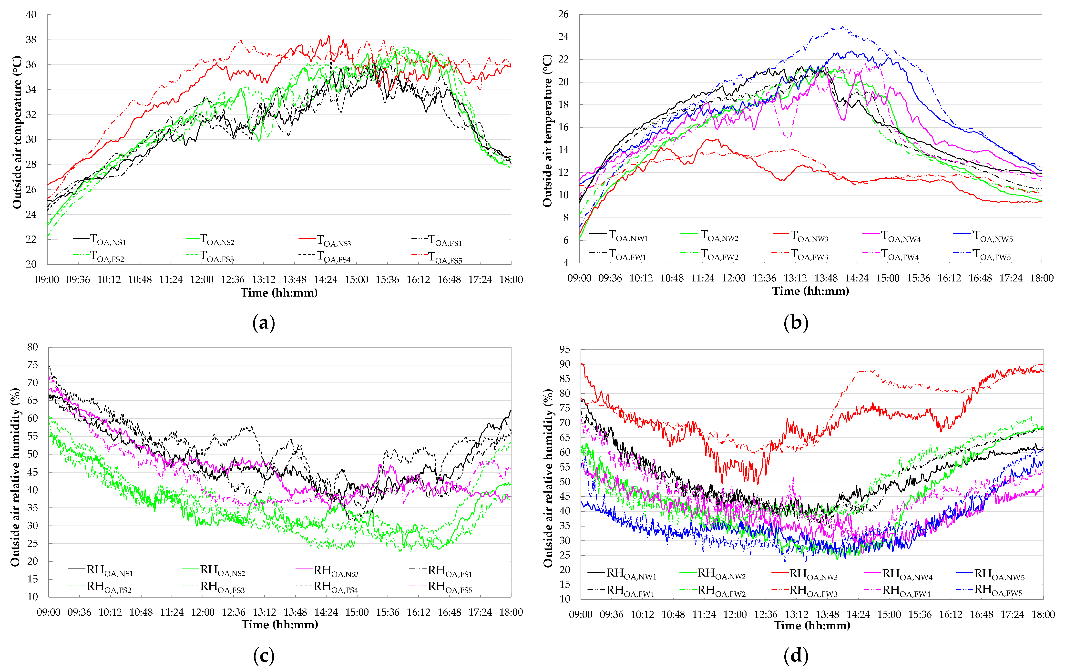
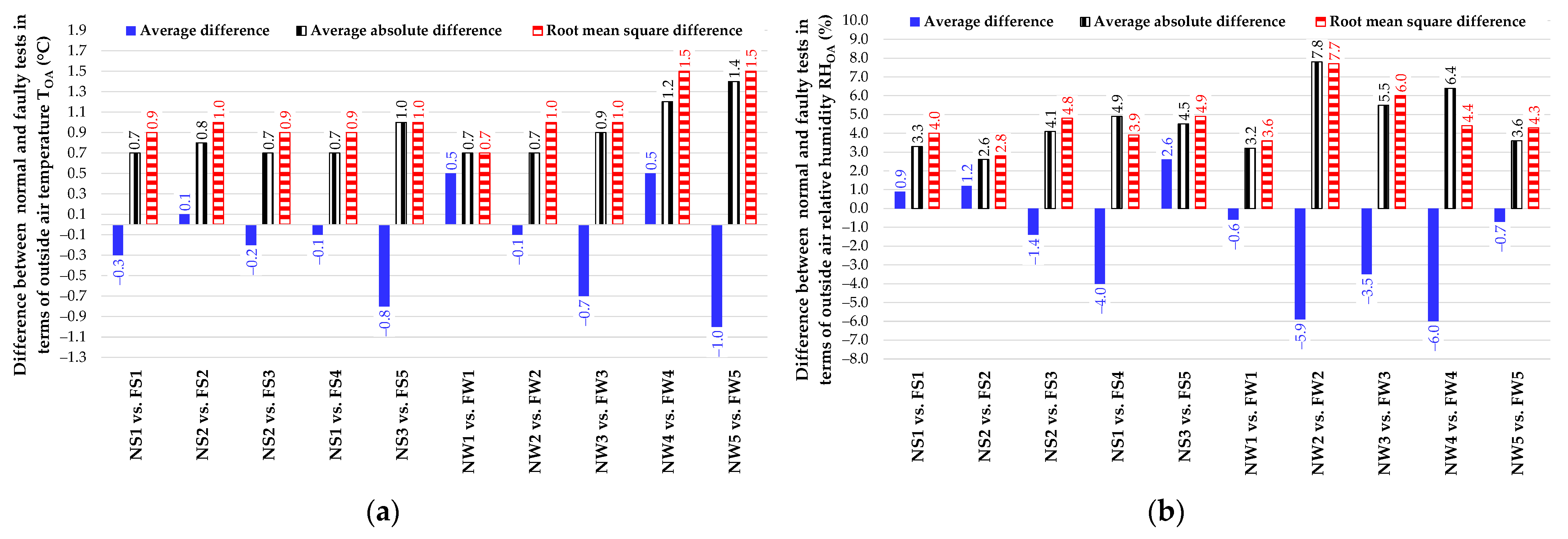
4. Comparison of Boundary Conditions between Fault-Free and Faulty Tests
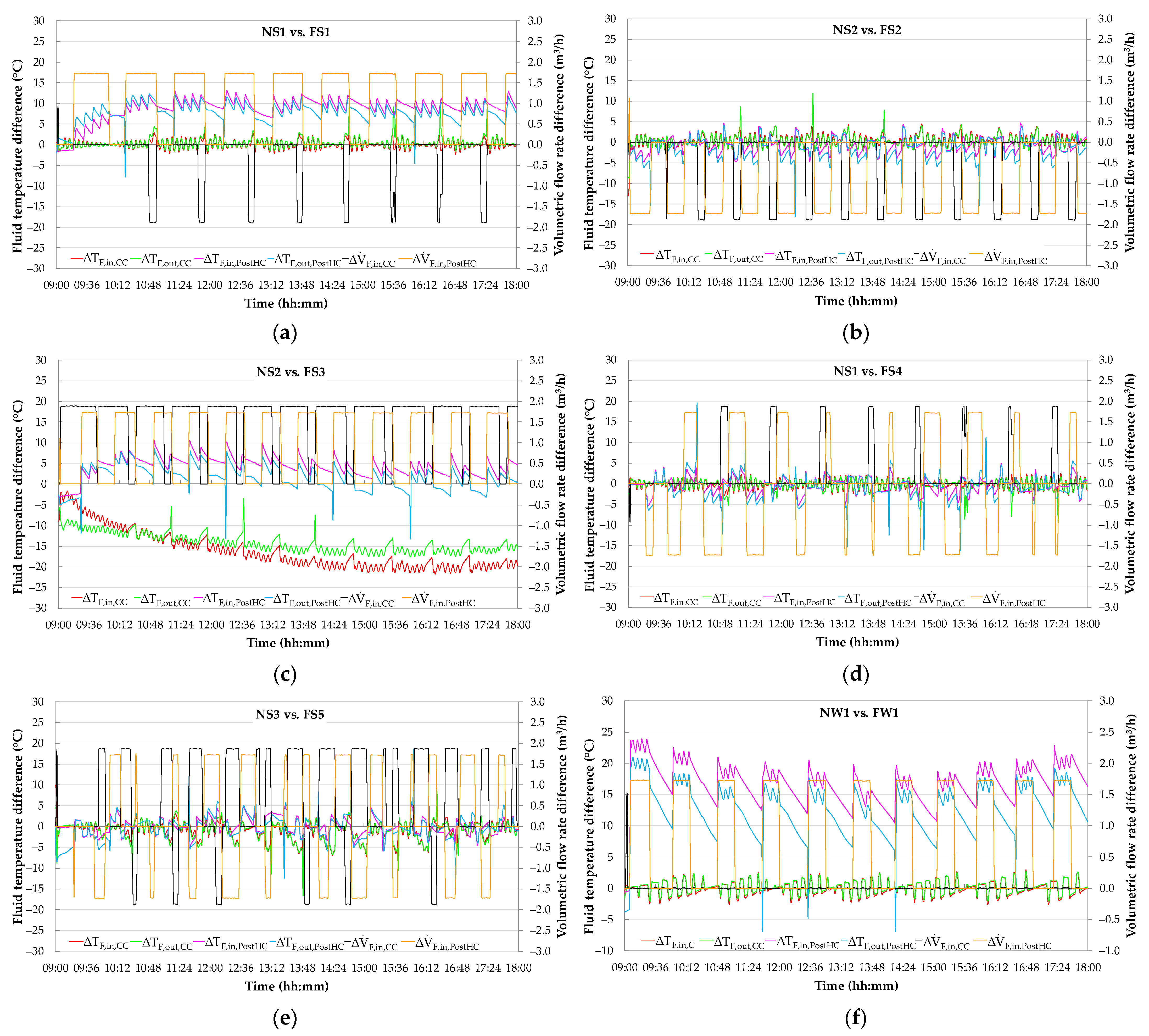
- the fault-free test NS1 is comparable with both the faulty tests FS1 and FS4;
- the fault-free experiment NS2 is similar to both the faulty experiments FS2 and FS3;
- the fault-free test NS3 matches the faulty test FS5;
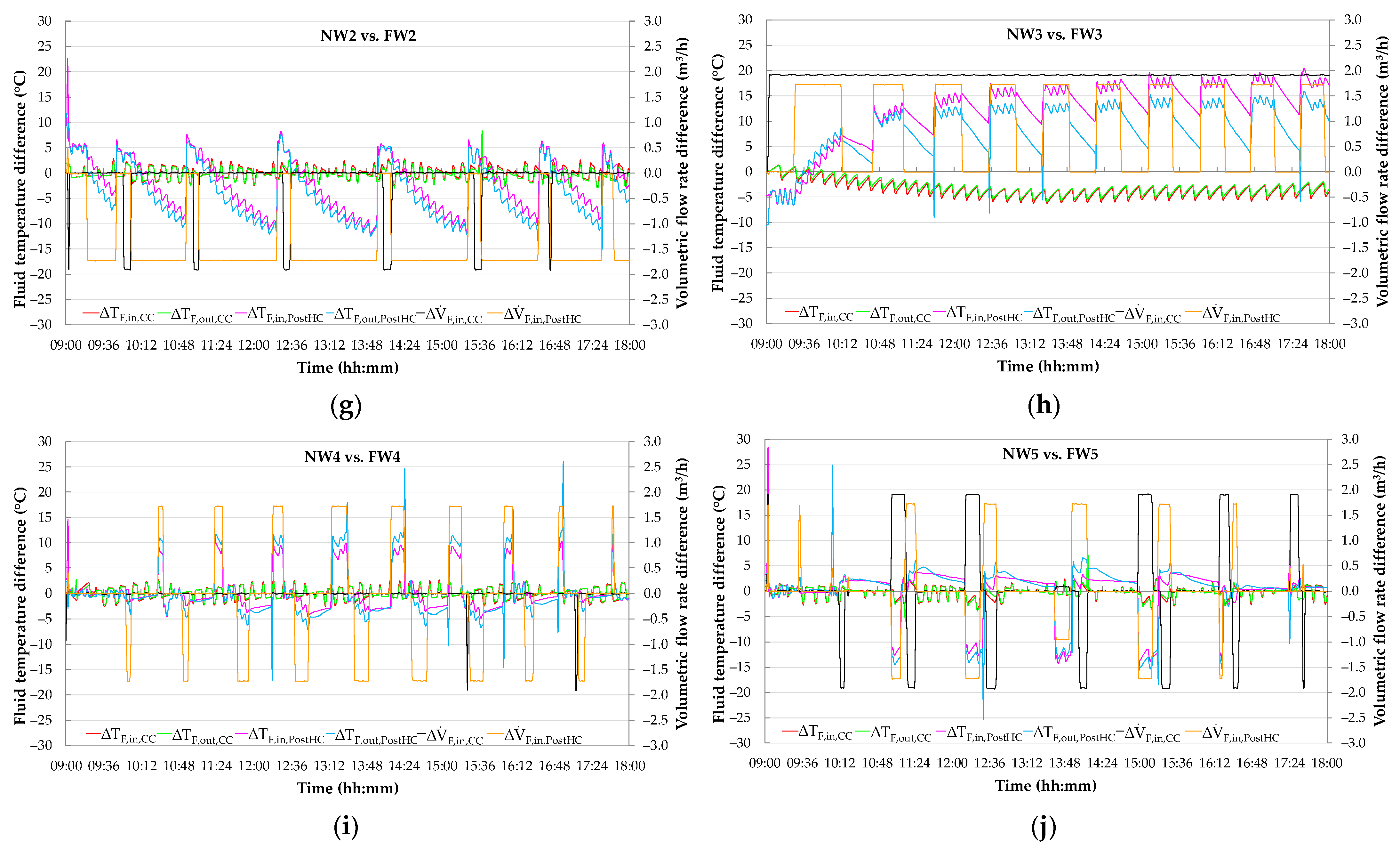
- the faulty test FW1 is similar to the fault-free test NW1;
- the faulty experiment FW2 is comparable with the fault-free test NW2;
- the fault-free test NW3 matches the faulty test FW3;
- the faulty experiment FW4 is similar to the fault-free test NW4;
- the fault-free test NW5 is comparable with the faulty test FW5.
5. Experimental Symptoms of Typical Faults on HVAC Performance
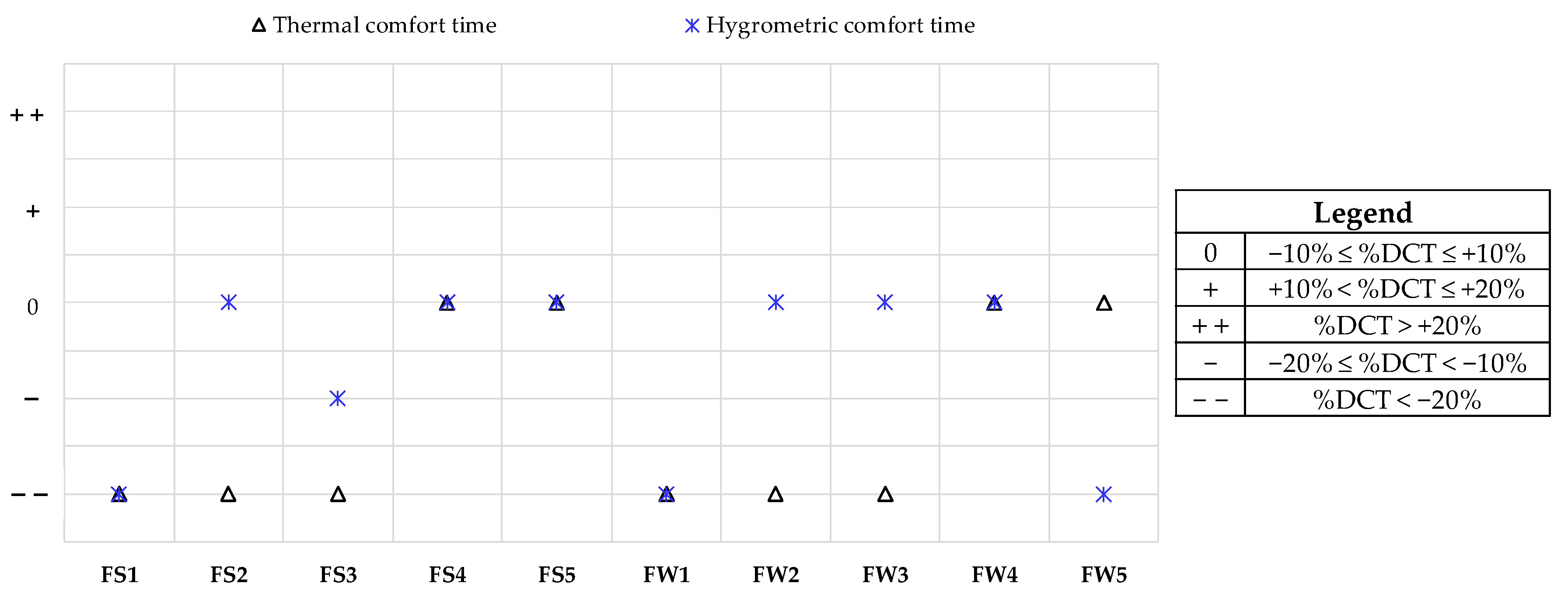
5.1. Effects of Faults on Thermal and Hygrometric Comfort
- ΔTout,DBT is the difference between the actual return air temperature TRA and the corresponding upper deadband UDBT or lower deadband LDBT, calculated only in the cases where TRA falls out of its deadbands;
- ΔRHout,DBRH is the difference between the actual return air relative humidity RHRA and the corresponding upper deadband UDBRH or lower deadband LDBRH, calculated only when RHRA falls out of its deadbands;
- Nout,DBT and Nout,DBRH are the number of experimental data points where TRA and RHRA are out of the corresponding deadbands, respectively.
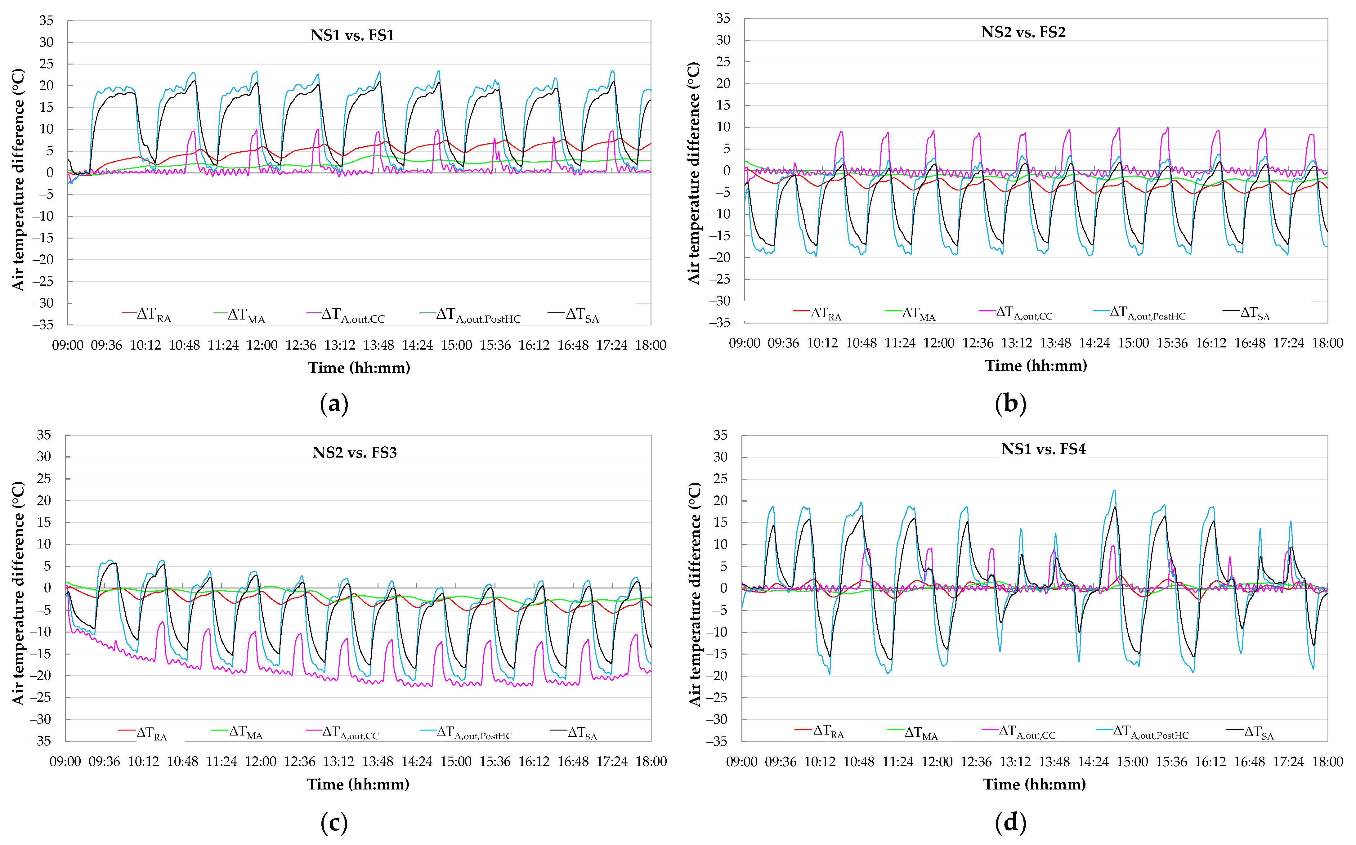
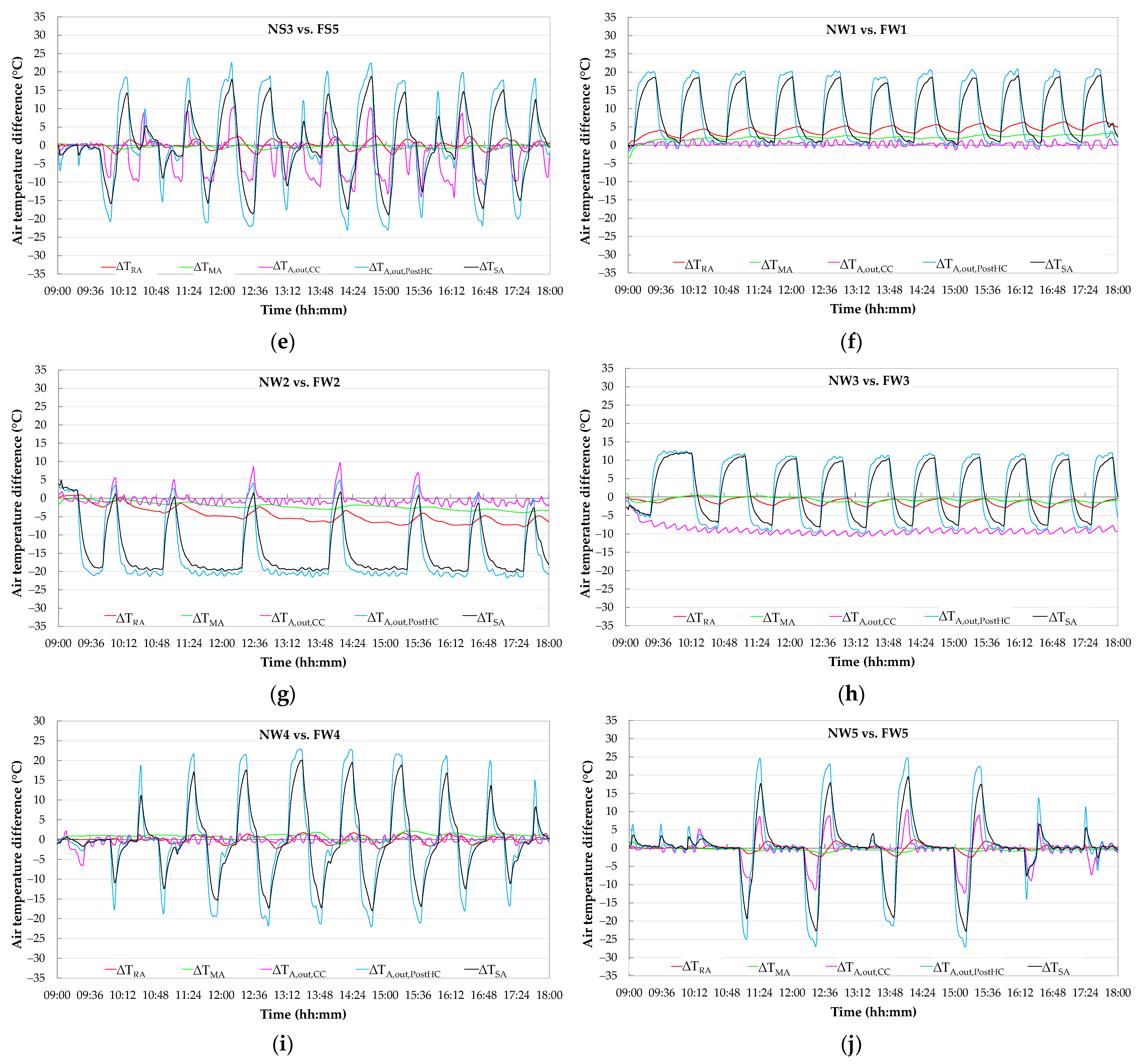
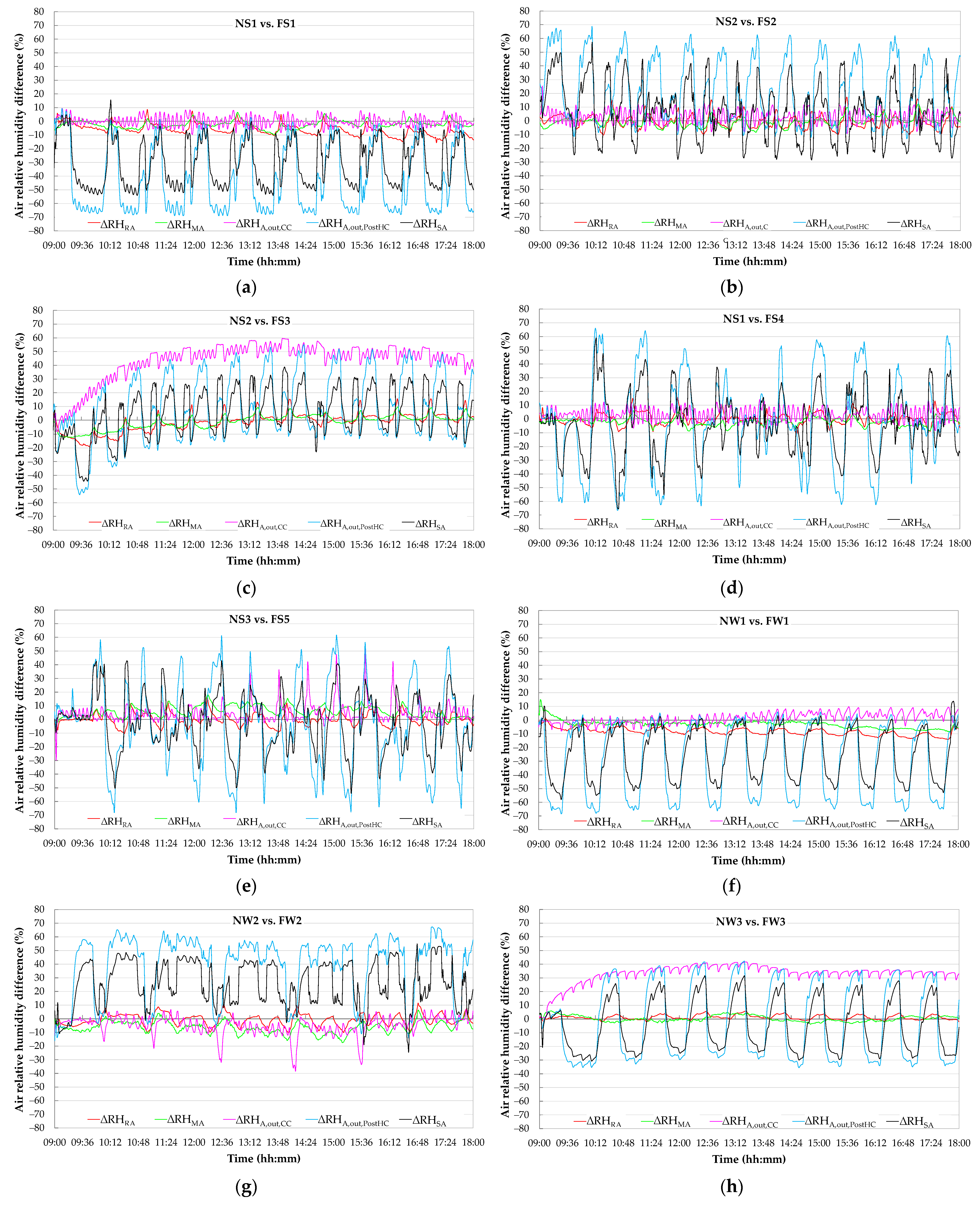
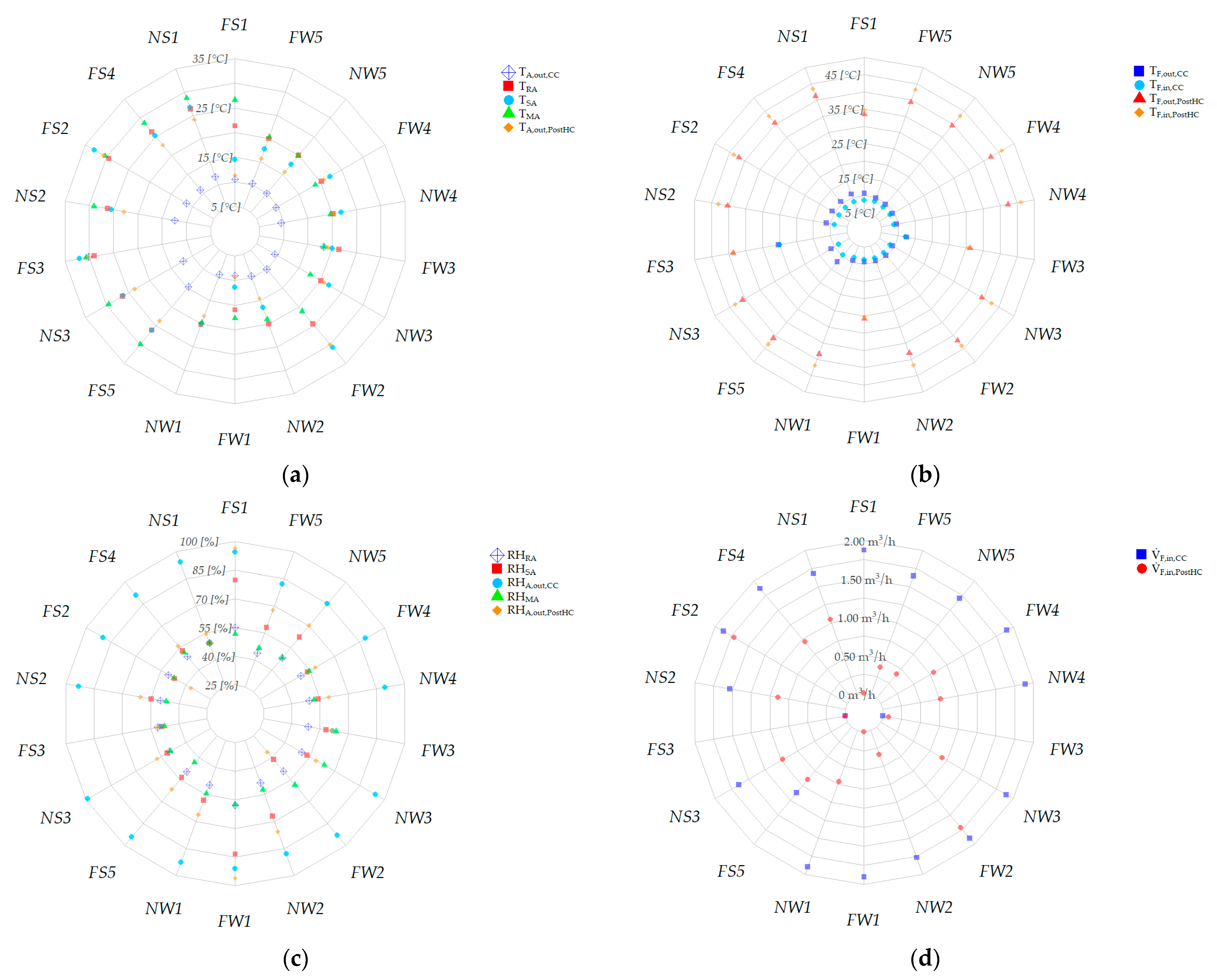
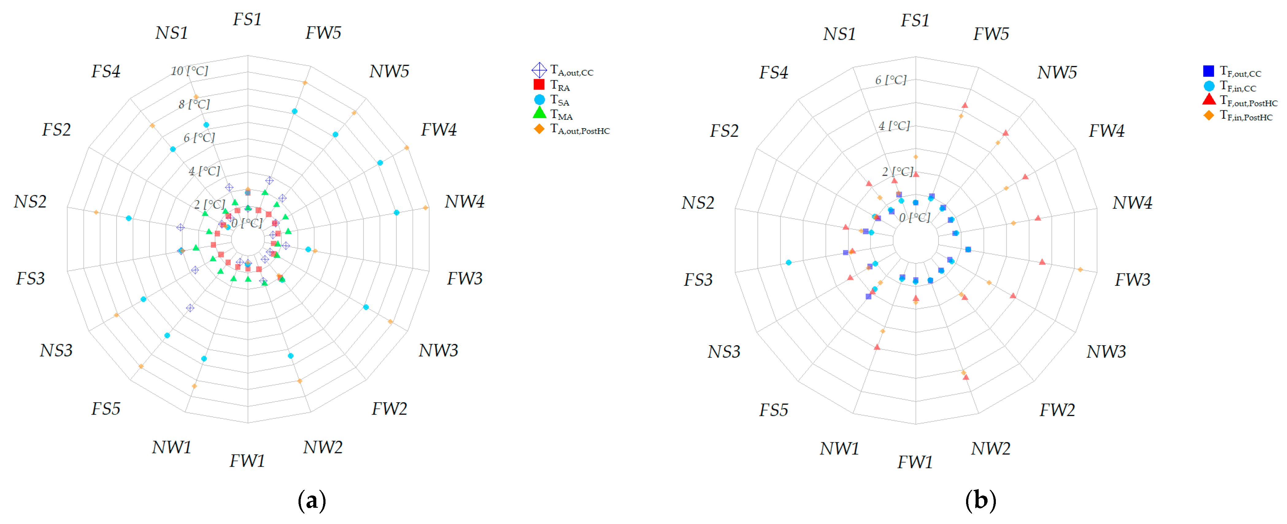
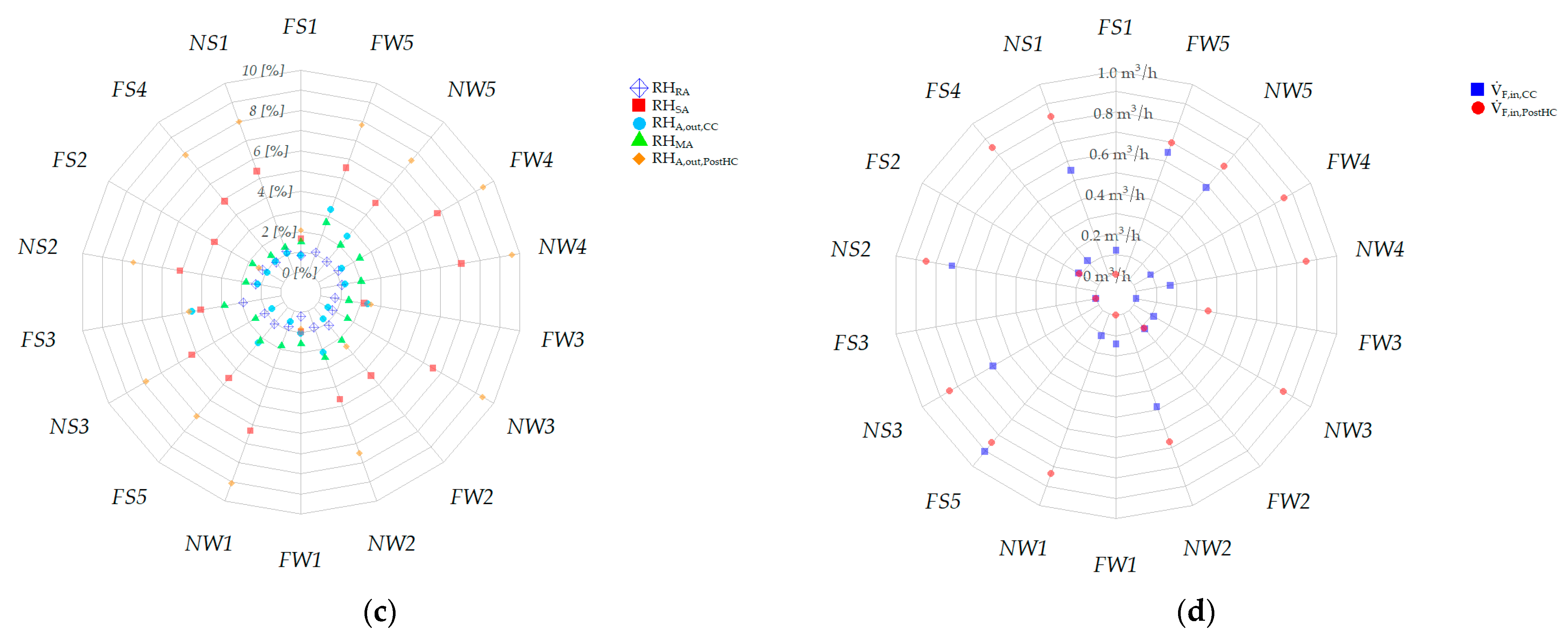
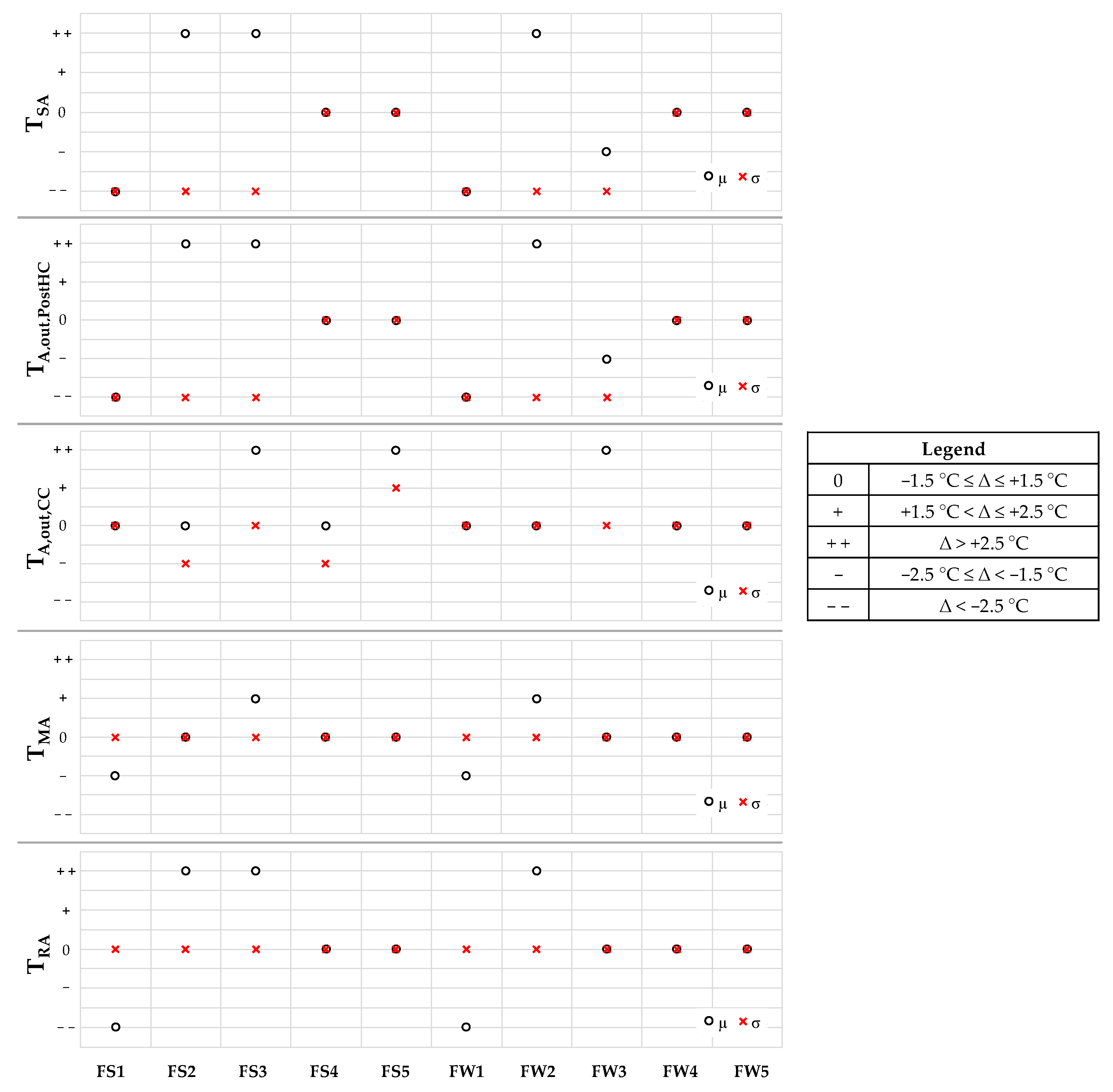
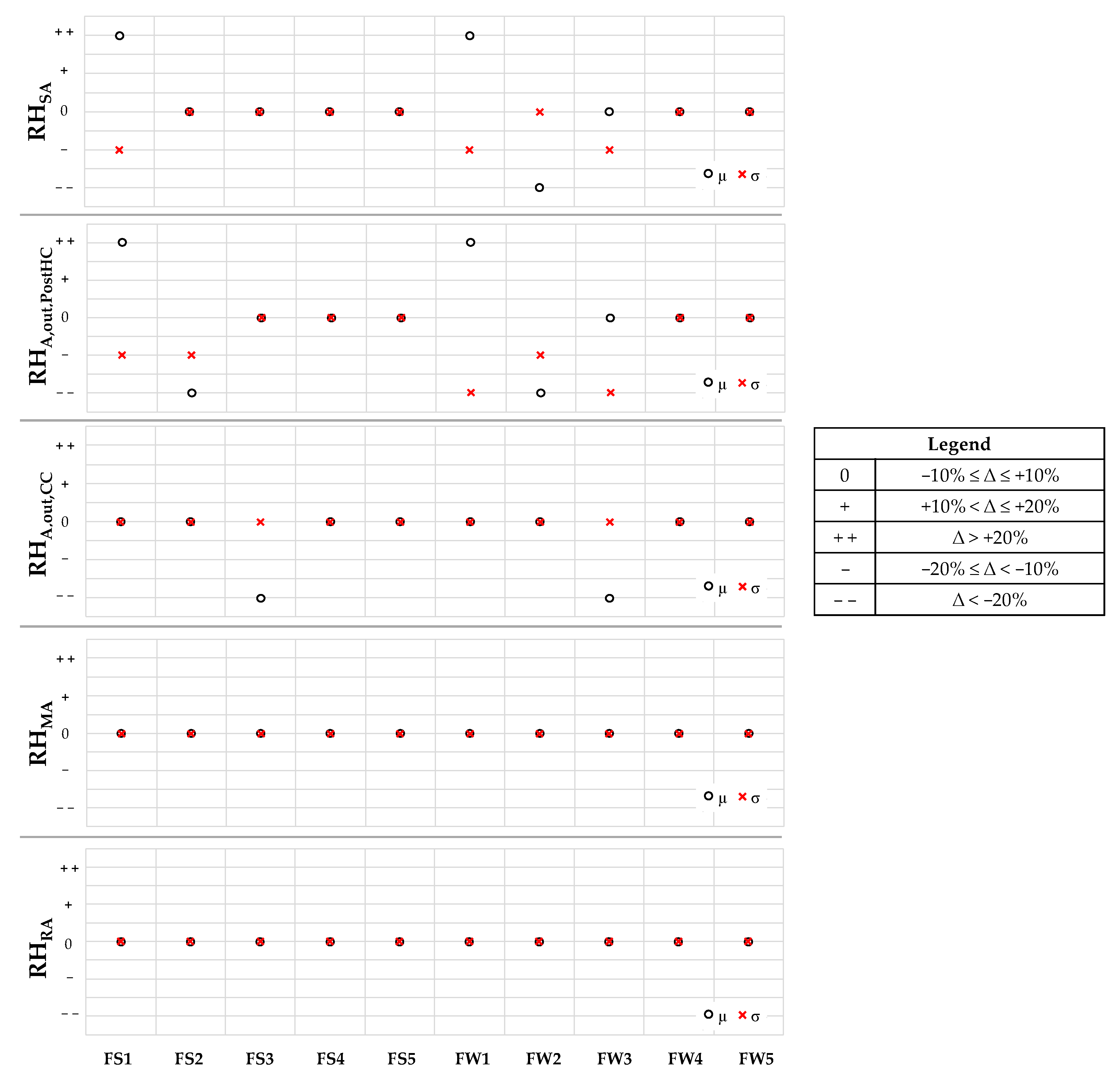
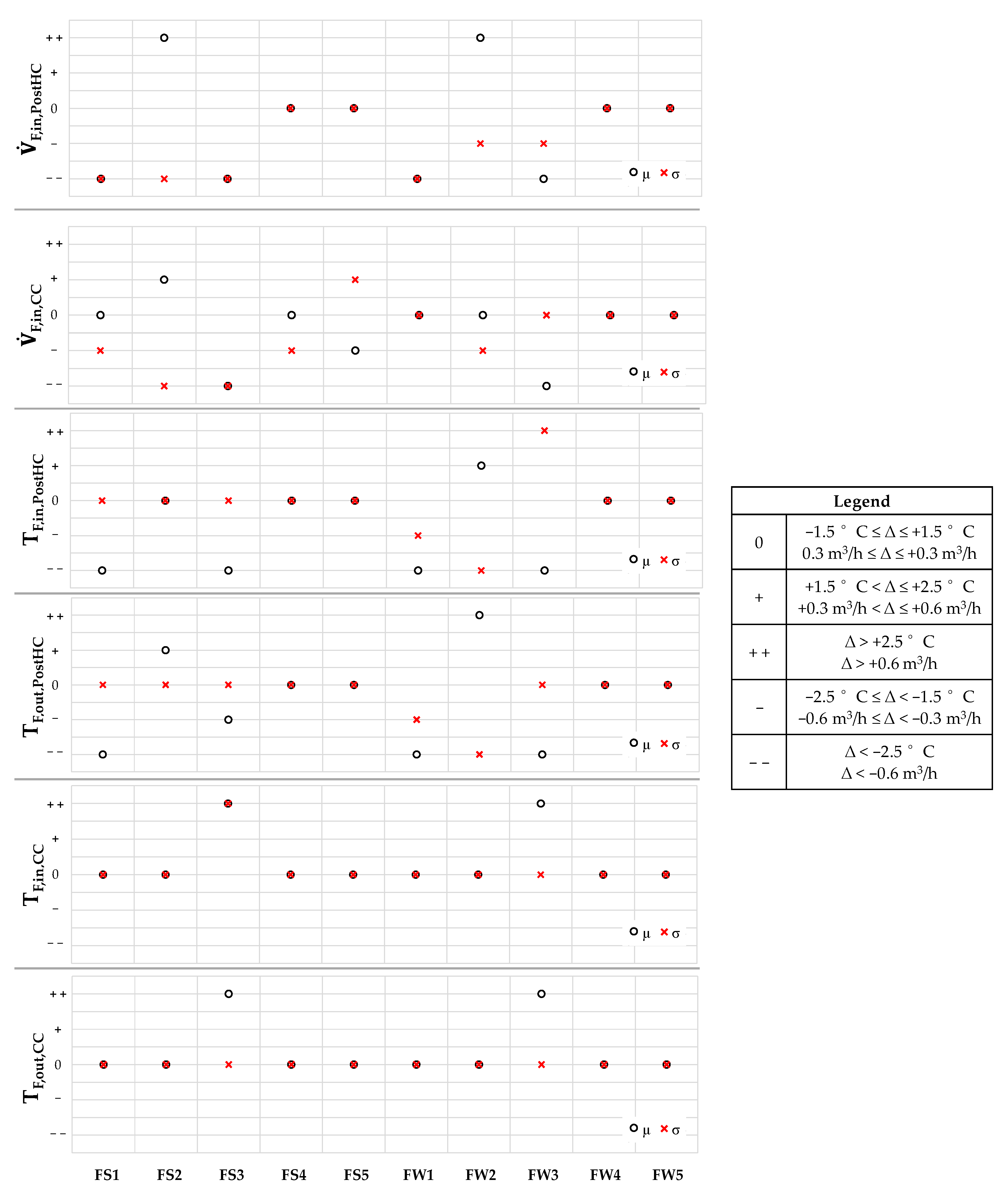
5.2. Effects of Faults on the Patterns of Key Operating Parameters and Evaluation of Symptom Probability
5.3. Discussion
- “0” means that the fault causes no substantial changes;
- “+” means that the fault causes slightly positive changes;
- “+ +” means that the fault causes substantial positive changes;
- “-” means that the fault causes slightly negative changes;
- “- -” means that the fault causes substantial negative changes.
6. Conclusions
Author Contributions
Funding
Institutional Review Board Statement
Informed Consent Statement
Data Availability Statement
Acknowledgments
Conflicts of Interest
Nomenclature
| Latin letters | |
| AFDD | Automatic fault detection and diagnosis |
| AHU | Air-handling unit |
| CC | Cooling coil |
| CT | Cold tank |
| CTBaseline | Comfort time of normal experimental tests |
| CTFaulty | Comfort time of faulty experimental tests |
| DBRH | Deadband of RHSP,Room (%) |
| DBT | Deadband of TSP,Room (°C) |
| DEA | Exhaust air damper |
| DOA | Outside air damper |
| DHRS | Damper of the heat recovery system |
| DRA | Return air damper |
| EA | Exhaust air |
| EXPOA,Baseline,i | Experimental value of TOA or ROA at time step i under fault-free conditions (°C) |
| EXPOA,Faulty,i | Experimental value of TOA or ROA at time step i under faulty conditions (°C) |
| EXPFaulty,i | Experimental value at time step i under faulty conditions |
| FS1 | Faulty test with the post-heating coil valve always kept closed during summer |
| FS2 | Faulty test with the post-heating coil valve always kept open during summer |
| FS3 | Faulty test with the cooling coil valve always kept closed during summer |
| FS4 | Faulty test with the cooling coil valve always kept open during summer |
| FS5 | Faulty test with the humidifier valve always kept closed during summer |
| FW1 | Faulty test with the post-heating coil valve always kept closed during winter |
| FW2 | Faulty test with the post-heating coil valve always kept open during winter |
| FW3 | Faulty test with the cooling coil valve always kept closed during winter |
| FW4 | Faulty test with the cooling coil valve always kept open during winter |
| FW5 | Faulty test with the humidifier valve always kept closed during winter |
| GHG | Greenhouse gas |
| HP | Heat pump |
| HRS | Static cross-flow heat recovery system |
| HT | Hot tank |
| HUM | Humidifier |
| HVAC | Heating, Ventilation and Air-Conditioning |
| LDBRH | Lower deadband of indoor air relative humidity (%) |
| LDBT | Lower deadband in indoor air temperature (°C) |
| N | Number of experimental data points |
| NS1 | Normal summer test n°1 |
| NS2 | Normal summer test n°2 |
| NS3 | Normal summer test n°3 |
| NW1 | Normal winter test n°1 |
| NW2 | Normal winter test n°2 |
| NW3 | Normal winter test n°3 |
| NW4 | Normal winter test n°4 |
| NW5 | Normal winter test n°5 |
| Nout,DBT | Number of experimental data points with TRA out of the corresponding deadband |
| Nout,DBRH | Number of experimental data points with RHRA out of the corresponding deadband |
| OAD | Outside air duct |
| OAFil | Outside air filter |
| OLRAF | Velocity of the return air fan (%) |
| OLSAF | Velocity of the supply air fan (%) |
| OPDEA | Opening percentage of the DEA (%) |
| OPDHRS | Opening percentage of the DHRS (%) |
| OPDOA | Opening percentage of the DOA (%) |
| OPDRA | Opening percentage of the DRA (%) |
| OPV_CC | Opening percentage of valve regulating the flow entering the CC (%) |
| OPV_HUM | Opening percentage of valve regulating the flow exiting the HUM (%) |
| OPV_PostHC | Opening percentage of valve regulating the flow entering the PostHC (%) |
| OPV_PreHC | Opening percentage of valve regulating the flow entering the PreHC (%) |
| PID | Proportional-integral-derivative |
| PostHC | Post-heating coil |
| PreHC | Pre-heating coil |
| RAD | Return air duct |
| RAF | Return air fan |
| RAFil | Return air filter |
| RAV | Return air vent |
| RHA,out,CC | Cooling coil outlet air relative humidity (%) |
| RHA,out,CC,Baseline | Measured cooling coil outlet air relative humidity under fault-free conditions (%) |
| RHA,out,CC,Faulty | Measured cooling coil outlet air relative humidity under faulty conditions (%) |
| RHA,out,PostHC | Post-heating coil outlet air relative humidity (%) |
| RHA,out,PostHC,Baseline | Measured post-heating coil outlet air relative humidity under fault-free conditions (%) |
| RHA,out,PostHC,Faulty | Measured post-heating coil outlet air relative humidity under faulty conditions (%) |
| RHMA | Mixed air relative humidity (%) |
| RHMA,Baseline | Measured mixed air relative humidity under fault-free conditions (%) |
| RHMA,Faulty | Measured mixed air relative humidity under faulty conditions (%) |
| RHOA | Outside air relative humidity (%) |
| RHRA | Return air relative humidity (%) |
| RHRA,Baseline | Measured return air relative humidity under fault-free conditions (%) |
| RHRA,initial | Initial indoor return air relative humidity (%) |
| RHRA,Faulty | Measured return air relative humidity under faulty conditions (%) |
| RHRoom | Air relative humidity inside the integrated test room (%) |
| RHSA | Supply air relative humidity (%) |
| RHSA,Baseline | Measured supply air relative humidity under fault-free conditions (%) |
| RHSA,Faulty | Measured supply air relative humidity under faulty conditions (%) |
| RHSP,Room | Desired target of indoor air relative humidity (%) |
| RMSD | Root mean square difference (°C/%) |
| RS | Refrigerating system |
| SAD | Supply air duct |
| SAF | Supply air fan |
| SAFil | Supply air filter |
| SAV | Supply air vent |
| SOP | Symptom Occurrence Probability (%) |
| t | Threshold value (equal to one) |
| TA,out,CC | Air temperature at the outlet of the cooling coil (°C) |
| TA,out,CC,Baseline | Measured air temperature at the outlet of the cooling coil under fault-free conditions (°C) |
| TA,out,CC,Faulty | Measured air temperature at the outlet of the cooling coil under faulty conditions (°C) |
| TA,out,PostHC | Air temperature at the outlet of the post-heating coil (°C) |
| TA,out,PostHC,Baseline | Measured air temperature at the outlet of the post-heating coil under fault-free conditions (°C) |
| TA,out,PostHC,Faulty | Measured air temperature at the outlet of the post-heating coil under faulty conditions (°C) |
| TCT | Heat carrier fluid temperature inside the cold tank (°C) |
| TCT,set-point | Target temperature of heat carrier fluid temperature inside the cold tank (°C) |
| TF,in,CC | Heat carrier fluid temperature at cooling coil inlet (°C) |
| TF,in,HP | Heat carrier fluid temperature at heat pump outlet (°C) |
| TF,in,PostHC | Heat carrier fluid temperature at post-heating coil inlet (°C) |
| TF,in,PostHC,Baseline | Heat carrier fluid temperature at post-heating coil inlet under fault-free conditions (°C) |
| TF,in,PostHC,Faulty | Heat carrier fluid temperature at post-heating coil inlet under faulty conditions (°C) |
| TF,in,PreHC | Heat carrier fluid temperature at pre-heating coil inlet (°C) |
| TF,in,RS | Heat carrier fluid temperature at refrigerating system inlet (°C) |
| TF,out,CC | Heat carrier fluid temperature at cooling coil outlet (°C) |
| TF,out,CC,Baseline | Heat carrier fluid temperature at cooling coil outlet under fault-free conditions (°C) |
| TF,out,CC,Faulty | Heat carrier fluid temperature at cooling coil outlet under faulty conditions (°C) |
| TF,out,HP | Heat carrier fluid temperature at heat pump outlet (°C) |
| TF,out,PostHC | Heat carrier fluid temperature at post-heating coil outlet (°C) |
| TF,out,PostHC,Baseline | Heat carrier fluid temperature at post-heating coil outlet under fault-free conditions (°C) |
| TF,out,PostHC,Faulty | Heat carrier fluid temperature at post-heating coil outlet under faulty conditions (°C) |
| TF,out,PreHC | Heat carrier fluid temperature at pre-heating coil outlet (°C) |
| TF,out,RS | Heat carrier fluid temperature at refrigerating system outlet (°C) |
| THT | Heat carrier fluid temperature inside the hot tank (°C) |
| THT,set-point | Target temperature of heat carrier fluid temperature inside the hot tank (°C) |
| TMA | Mixed air temperature (°C) |
| TMA,Baseline | Measured mixed air temperature under fault-free conditions (°C) |
| TMA,Faulty | Measured mixed air temperature under faulty conditions (°C) |
| TOA | Outside air temperature (°C) |
| TRA | Return air temperature (°C) |
| TRA,Baseline | Measured return air temperature under fault-free conditions (°C) |
| TRA,initial | Initial return air temperature (°C) |
| TRA,Faulty | Measured return air temperature under faulty conditions (°C) |
| TRoom | Air temperature inside the integrated test room (°C) |
| TSA | Supply air temperature (°C) |
| TSA,Baseline | Measured supply air temperature under fault-free conditions (°C) |
| TSA,Faulty | Measured supply air temperature under faulty conditions (°C) |
| TSP,Room | Desired target of indoor air temperature (°C) |
| UDBRH | Upper deadband of indoor air relative humidity (%) |
| UDBT | Upper deadband of indoor air temperature (°C) |
| VAV | Variable air volume |
| VCC | Three-way valves supplying the cooling coil |
| VHUM | Three-way valve supplying the humidifier |
| VPostHC | Three-way valve supplying the post-heating coil |
| VPreHC | Three-way valve supplying the pre-heating coil |
| Volumetric flow rate of heat carrier fluid entering the cooling coil (m3/h) | |
| Volumetric flow rate of heat carrier fluid entering the cooling coil under fault-free conditions (m3/h) | |
| Volumetric flow rate of heat carrier fluid entering the cooling coil under faulty conditions (m3/h) | |
| Volumetric flow rate of heat carrier fluid entering the post-heating coil (m3/h) | |
| Volumetric flow rate of heat carrier fluid entering the post-heating coil under fault-free conditions (m3/h) | |
| Volumetric flow rate of heat carrier fluid entering the post-heating coil under faulty conditions (m3/h) | |
| Volumetric flow rate of heat carrier fluid entering the pre-heating coil (m3/h) | |
| XBaseline | Arithmetic mean m or standard deviation s calculated based on the measured values under normal conditions |
| XFaulty | Arithmetic mean m or standard deviation s calculated based on the measured values under faulty conditions |
| ∆RHout,DBT | Difference between RHRA and UDBRH calculated in the case of RHRA is larger than UDBRH, or the difference between LDBRH and RHRA in the case of RHRA is lower than LDBRH |
| ∆Tout,DBRH | Difference between RHRA and UDBRH calculated in the case of RHRA is larger than UDBRH, or the difference between LDBRH and RHRA in the case of RHRA is lower than LDBRH |
| ∆Tout,DBT | Difference between TRA and UDBT calculated in the case of TRA is larger than UDBT, or the difference between LDBT and TRA in the case of TRA is lower than LDBT |
| %DCT | Percentage comfort time difference (%) |
| %VGlycol,PreHC | Percentage by volume of glycol in the heat carrier fluid entering the PreHC |
| %VGlycol,CC | Percentage by volume of glycol in the heat carrier fluid entering the CC |
| %VGlycol,PostHC | Percentage by volume of glycol in the heat carrier fluid entering the PostHC |
| Greek | |
| ∆ | Difference |
| εi | Instantaneous difference (°C/%) |
| Average error (°C/%) | |
| Absolute average error (°C/%) | |
| Intensity of thermal discomfort time (°C) | |
| Intensity of hygrometric discomfort time (%) | |
| μ | Arithmetic mean (°C/%) |
| σ | Standard deviation (°C/%) |
| μBaseline | Arithmetic mean under normal conditions (°C/%) |
| σBaseline | Standard deviation under normal conditions (°C/%) |
Appendix A
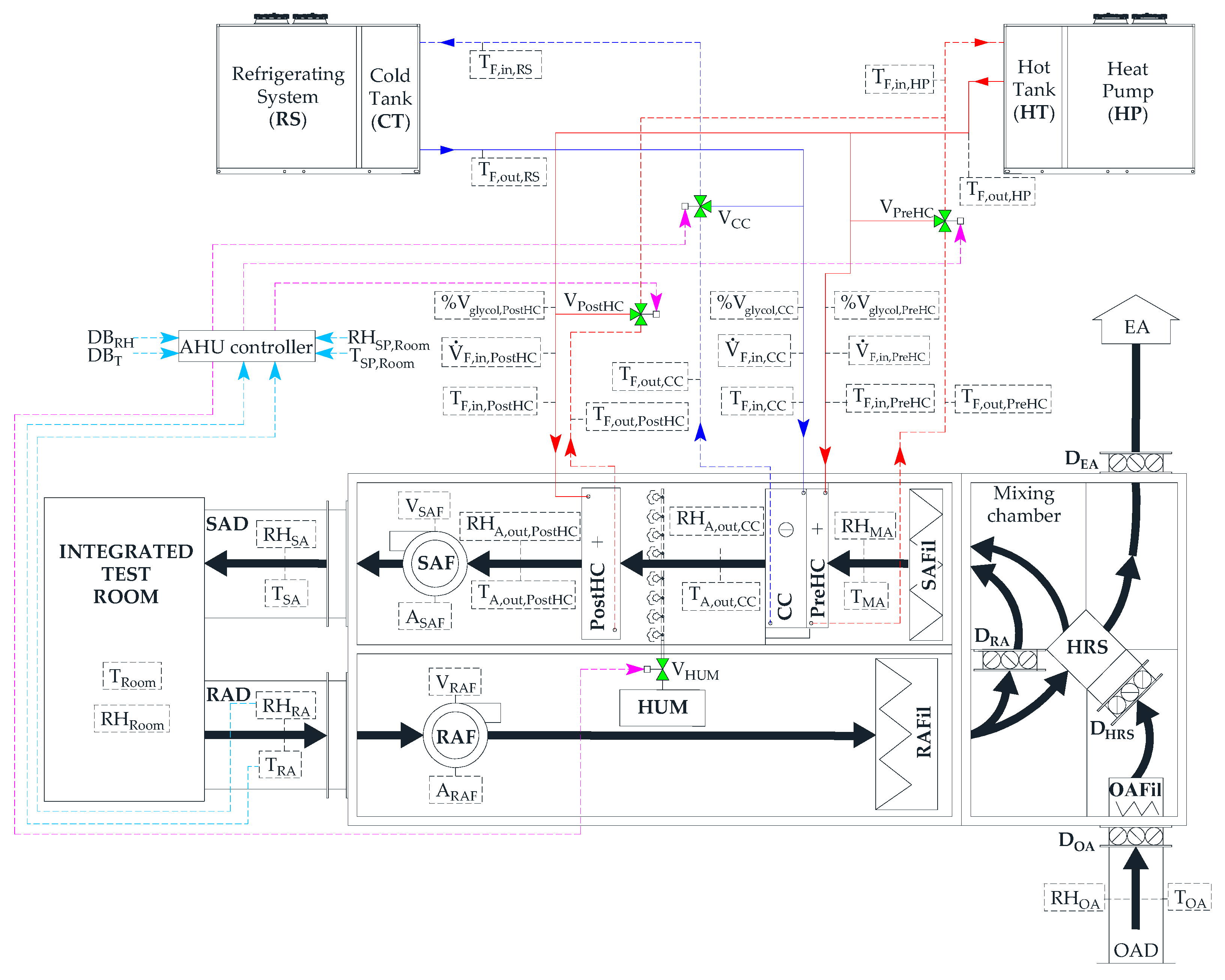
- the refrigeration machine operates to maintain a temperature TCT equal to TCT,set-point (with a deadband of 1 °C) inside the 75 L cold tank, while the heat pump is activated in order to achieve a temperature THT equal to THT,set-point (with a deadband of 1 °C) inside the 75 L hot tank;
- the desired return air temperature and relative humidity are kept at a chosen set-point (with defined deadbands) by regulating both the supply air temperature and the supply air relative humidity, while maintaining a constant air flow rate to the room;
- PID (proportional-integral-derivative) controllers automatically adjust (in the range 0–100%) the opening percentages of the valves (OPV_PreHC, OPV_PostHC, OPV_CC and OPV_HUM) supplying the pre-heating coil, the post-heating coil, the cooling coil and the humidifier, respectively, with the aim of achieving the desired targets inside the test room;
- if the actual return air temperature TRA is beyond the upper deadband UDBT of the indoor air temperature set-point TSP,Room (UDBT = TSP,Room + DBT), the cooling coil valve PID loop is enabled and the cooling coil valve position is controlled in the range 0–100% by the cooling coil valve controller PID output in order to achieve the lower deadband LDBT (LDBT = TSP,Room − DBT) of the indoor air temperature set-point thanks to the reduction of supply air temperature; once this desired temperature level is reached, the post-heating coil is activated in order to increase the return air temperature up to the UDBT by enhancing the supply air temperature; then, the cooling coil is activated again in order to reach the LDBT and so forth; therefore, the HVAC system aims to maintain the return air temperature between LDBT and UDBT, whatever the season is;
- when the actual return air temperature TRA falls below the LDBT, the cooling coil valve PID loop is disabled and the cooling coil valve is fully closed, except in the case when the indoor relative humidity has to be reduced;
- in the case of the actual return air temperature TRA falling below the LDBT, the heating coil valve PID loop is enabled and the heating coil valve position is regulated between 0 and 100% by the heating coil valve controller PID output in order to achieve a temperature level equal to the UDBT by increasing the supply air temperature; once this desired temperature level is reached, the cooling coil is activated in order to reduce the return air temperature down to the LDBT by lowering the supply air temperature; then, the heating coil is activated again in order to reach the UDBT and so forth; therefore, the HVAC system aims to maintain the return air temperature between LDBT and UDBT, whatever the season is;
- when the actual return air temperature TRA is beyond the UDBT, the heating coil valve PID loop is disabled and the heating coil valve is fully closed;
- in the case of the actual return air relative humidity RHRA being beyond the upper deadband UDBRH of the indoor air relative humidity set-point RHSP,Room (UDBRH = RHSP,Room + DBRH), the cooling coil valve PID loop is enabled and the cooling coil valve position is managed in the range 0–100% by the cooling coil valve controller PID output in order to achieve the lower deadband LDBRH of the indoor air relative humidity set-point RHSP,Room (LDBRH = RHSP,Room − DBRH); once this relative humidity is reached, the humidifier valve PID loop is enabled and the humidifier valve position is varied in the range 0-100% by the humidifier valve controller PID in order to increase the return air relative humidity up to the UDBRH; then, the cooling coil is activated again in order to reach the LDBRH and so forth; therefore, the HVAC system aims to maintain the return air relative humidity between LDBRH and UDBRH, whatever the season is;
- if the actual return air relative humidity RHRA falls below the LDBRH, the humidifier valve PID loop is enabled and the humidifier valve position is controlled between 0 and 100% by the humidifier valve controller PID output with the aim of achieving an indoor air relative humidity level equal to the UDBRH while the cooling coil valve PID loop is disabled and the cooling coil valve is fully closed (except in the case when the indoor air temperature has to be reduced); once this relative humidity level is achieved, the cooling coil is activated in order to reduce the return air relative humidity down to the level LDBRH; then, the humidifier is activated again in order to reach the indoor air relative humidity of UDBRH and so forth; therefore, the HVAC system aims to keep the return air relative humidity between LDBRH and UDBRH, whatever the season is;
- if both (i) the actual return air temperature TRA is beyond the upper deadband UDBT and (ii) the actual return air relative humidity RHRA is beyond the upper deadband UDBRH, the control of return air relative humidity has priority and, therefore, the cooling coil valve PID loop is enabled and the cooling coil valve position is operated via the PID to firstly achieve the lower deadband LDBRH; once this lower deadband LDBRH is obtained, the cooling coil valve PID loop is still enabled with the aim of reaching the lower deadband LDBT only in the case of the actual return air temperature TRA still being beyond the upper deadband UDBT (otherwise the cooling coil loop is disabled).
Appendix B


Appendix C

References
- 2021 Global Status Report for Buildings and Construction. Towards a Zero-Emission, Efficient and Resilient Buildings and Construction Sector. Available online: https://globalabc.org/sites/default/files/2021-10/GABC_Buildings-GSR-2021_BOOK.pdf (accessed on 1 August 2022).
- Cao, X.; Dai, X.; Liu, J. Building energy-consumption status worldwide and the state-of-the-art technologies for zero-energy buildings during the past decade. Energy Build. 2016, 128, 198–213. [Google Scholar] [CrossRef]
- Yun, W.S.; Hong, W.H.; Seo, H. A data-driven fault detection and diagnosis scheme for air handling units in building HVAC systems considering undefined states. J. Build. Eng. 2021, 35, 102111. [Google Scholar] [CrossRef]
- Mirnaghi, M.S.; Haghighat, F. Fault detection and diagnosis of large-scale HVAC systems in buildings using data-driven methods: A comprehensive review. Energy Build. 2020, 229, 110492. [Google Scholar]
- Proctor, J. Residential and small commercial central air conditioning; rated efficiency isn’t automatic. In Proceedings of the ASHRAE Winter Meeting, Anaheim, CA, USA 24–28 January 2004. [Google Scholar]
- Rossi, T.M. Unitary air conditioner field performance. In Proceedings of the International Refrigeration and Air Conditioning Conference, West Lafayette, IN, USA, 12–15 July 2004. [Google Scholar]
- Schein, J.; Bushby, S.T.; Castro, N.S.; House, J.M. A rule-based fault detection method for air handling units. Energy Build. 2006, 38, 1485–1492. [Google Scholar] [CrossRef]
- Katipamula, S.; Brambley, M.R. Methods for fault detection, diagnostics, and prognostics for building systems—A review, part II. HVACR Res. 2005, 11, 169–187. [Google Scholar] [CrossRef]
- Wu, S.; Sun, J.Q. Cross-level fault detection and diagnosis of building HVAC systems. Build. Environ. 2011, 46, 1558–1566. [Google Scholar] [CrossRef]
- Wang, H.; Chen, Y. A robust fault detection and diagnosis strategy for multiple faults of VAV air handling units. Energy Build. 2016, 127, 442–451. [Google Scholar] [CrossRef]
- Lin, G.; Kramer, H.; Granderson, J. Building fault detection and diagnostics: Achieved savings, and methods to evaluate algorithm performance. Build. Environ. 2020, 168, 106505. [Google Scholar] [CrossRef]
- Zhao, Y.; Li, T.; Zhang, X.; Zhang, C. Artificial intelligence-based fault detection and diagnosis methods for building energy systems: Advantages, challenges and the future. Renew. Sust. Energ. Rev. 2019, 109, 85–101. [Google Scholar] [CrossRef]
- Kim, W.; Katipamula, S. A review of fault detection and diagnostics methods for building systems. Sci. Technol. Built Environ. 2018, 24, 3–21. [Google Scholar] [CrossRef]
- Huang, J.; Wen, J.; Yoon, H.; Pradhan, O.; Wu, T.; O’Neill, Z.; Candan, K.S. Real vs. Simulated: Questions on the capability of simulated datasets on building fault detection for energy efficiency from a data-driven perspective. Energy Build. 2022, 259, 111872. [Google Scholar] [CrossRef]
- Frank, S.; Lin, G.; Jin, X.; Singla, R.; Farthing, A.; Granderson, J. A performance evaluation framework for building fault detection and diagnosis algorithms. Energy Build. 2019, 192, 84–92. [Google Scholar] [CrossRef]
- Yu, Y.; Woradechjumroen, D.; Yu, D. A review of fault detection and diagnosis methodologies on air-handling units. Energy Build. 2014, 82, 550–562. [Google Scholar] [CrossRef]
- Piscitelli, M.S.; Mazzarelli, D.M.; Capozzoli, A. Enhancing operational performance of AHUs through an advanced fault detection and diagnosis process based on temporal association and decision rules. Energy Build. 2020, 226, 110369. [Google Scholar] [CrossRef]
- Wen, J.; Li, S. RP-1312—Tools for evaluating fault detection and diagnostic methods for Air-Handling Units. American Society of Heating, Refrigeration and Air-Conditioning Engineers (ASHRAE), Final Report. 2012. Available online: https://www.techstreet.com/standards/rp-1312-tools-for-evaluating-fault-detection-and-diagnostic-methods-for-air-handling-units?product_id=1833299#product (accessed on 1 September 2022).
- Granderson, J.; Lin, G.; Singla, R.; Mayhorn, E.; Ehrlich, P.; Vrabie, D. Commercial Fault Detection and Diagnostics Tools: What They Offer, How They Differ, and What’s Still Needed. Lawrence Berkeley National Laboratory Recent Work. 2018, pp. 1–12. Available online: https://escholarship.org/uc/item/4j72k57p (accessed on 1 August 2022).
- Granderson, J.; Lin, G.; Harding, A.; Im, P.; Chen, Y. Building Fault Detection Data to Aid Diagnostic Algorithm Creation and Performance Testing. Sci. Data 2020, 7, 65. [Google Scholar] [CrossRef]
- Liu, R.; Zhou, X.; Milbrandt, R. Experimental Study of Lab Controlled Faults in Dual-Duct VAV System. In Proceedings of the ASHRAE Transactions, Atlanta, USA, 27 June–1 July 2015. [Google Scholar]
- Rosato, A.; Guarino, F.; Filomena, V.; Sibilio, S.; Maffei, L. Experimental calibration and validation of a simulation model for fault detection of HVAC systems and application to a case study. Energies 2020, 13, 3948. [Google Scholar] [CrossRef]
- Rosato, A.; Guarino, F.; Sibilio, S.; Entchev, E.; Masullo, M.; Maffei, L. Healthy and faulty experimental performance of a typical HVAC system under Italian climatic conditions: Artificial neural network-based model and fault impact assessment. Energies 2021, 14, 5362. [Google Scholar] [CrossRef]
- Rosato, A.; Guarino, F.; Youssef, M.; Sibilio, S.; Maffei, L. Preliminary symptoms assessment of typical faults related to the fans and humidifiers of HVAC systems based on experimental data collected during Italian summer and winter. In Proceedings of the IOP Conference Series: Earth and Environmental Science, 4th International Conference on Renewable Energy and Environment Engineering, Florence, Italy, 27–30 August 2021; IOP Publishing: Bristol, UK, 2021; Volume 897, p. 12009. [Google Scholar]
- Wu, B.; Cai, W.; Cheng, F.; Chen, H. Simultaneous-fault diagnosis considering time series with a deep learning transformer architecture for air handling units. Energy Build. 2022, 257, 111608. [Google Scholar] [CrossRef]
- Liao, H.; Cai, W.; Cheng, F.; Dubey, S.; Rajesh, P.B. An Online Data-Driven Fault Diagnosis Method for Air Handling Units by Rule and Convolutional Neural Networks. Sensors 2021, 21, 4358. [Google Scholar] [CrossRef]
- HVAC SIMulation PLUS other systems (HVACSIM+). Available online: https://www.nist.gov/services-resources/software/hvac-simulation-plus-other-systems-hvacsim (accessed on 1 August 2022).
- Casillas, A.; Lin, G.; Granderson, J. Curation of Ground-Truth Validated Benchmarking Datasets for Fault Detection & Diagnostics Tools; Lawrence Berkeley National Laboratory: Berkeley, CA, USA, 2021. Available online: https://eta-publications.lbl.gov/sites/default/files/curation_of_ground-truth_validated_benchmarking_datasets_for_fault_detection_acasillas_0.pdf (accessed on 1 August 2022).
- Hu, R.I.; Granderson, J.; Auslader, D.M.; Agogino, A. Design of machine learning models with domain experts for automated sensor selection for energy fault detection. Appl. Energy 2019, 235, 117–128. [Google Scholar] [CrossRef]
- Chen, Y.; Lin, G.; Chen, Z.; Wen, J.; Granderson, J. A simulation-based evaluation of fan coil unit fault effects. Energy Build. 2022, 263, 112041. [Google Scholar] [CrossRef]
- Li, Y.; O’Neill, Z. A critical review of fault modeling of HVAC systems in buildings. Build. Simul. 2018, 11, 953–975. [Google Scholar] [CrossRef]
- Dey, D.; Dong, B.; Li, Z. A Probabilistic Framework to Diagnose Faults in Air Handling Units. In Proceedings of the International High Performance Buildings Conference, West Lafayette, IN, USA, 11–14 July 2016; Available online: http://docs.lib.purdue.edu/ihpbc/168 (accessed on 1 September 2022).
- Nehasil, O.; Dobiášová, L.; Mazanec, V.; Široky, J. Versatile AHU fault detection–Design, field validation and practical application. Energy Build. 2021, 237, 110781–110792. [Google Scholar] [CrossRef]
- Feng, B.; Zhou, Q.; Xing, J.; Yang, Q.; Qin, X.; Mo, Y.; Chen, W. A fully distributed voting strategy for AHU fault detection and diagnosis based on a decentralized structure. Energy Rep. 2022, 8, 390–404. [Google Scholar] [CrossRef]
- Carling, P. Comparison of Three Fault Detection and Diagnosis Methods Based on Field Data of an Air Handling Unit. In Proceedings of the ASHRAE Transactions 108, Atlantic City, NJ, USA, 12 January 2002. [Google Scholar]
- SENS i-Lab, Department of Architecture and Industrial Design, University of Campania Luigi Vanvitelli. Available online: https://www.architettura.unicampania.it/images/ricerca/laboratori/EN/SENS-i_Lab_2021_EN.pdf (accessed on 1 August 2022).
- CAREL. Humidifiers Technical Datasheet. Available online: https://www.carel.com/documents/10191/0/%2B030220621/92fca658-a251-49ee-9979-b8829fcba49f?version=1.0 (accessed on 1 August 2022).
- AERMEC. Reversible Air/Water Heat Pump Technical Datasheet. Available online: https://download.aermec.com/docs/schede/ANL-021-203-HP_Y_UN50_03.pdf?r=14395 (accessed on 1 August 2022).
- Mastrullo, R.; Rosato, A.; Vanoli, G.P.; Thome, J.R. A methodology to select the experimental plant instrumentation based on an a priori analysis of measurement errors and instrumentation cost. Int. Commun. Heat Mass Transf. 2008, 35, 689–695. [Google Scholar] [CrossRef]
- SIEMENS. Duct Sensors Technical Datasheet. Available online: https://www.downloads.siemens.com/download-center/Download.aspx?pos=download&fct=getasset&id1=24897 (accessed on 1 August 2022).
- E+E Elektronic. EE210 Outdoor Datasheet. Available online: https://www.epluse.com/fileadmin/data/product/ee210/datasheet_EE210_Outdoor.pdf (accessed on 1 August 2022).
- TSI. Q-TRAK Technical Datasheet. Available online: https://tsi.com/getmedia/d2a8d1d1-7551-47fe-8a0f-3c14b09b494b/7575_QTrak_A4_UK_5001356-web?ext=.pdf (accessed on 1 August 2022).
- MEASUREIT. Sensors. Available online: https://shop.measureit.eu/sensori.html (accessed on 1 August 2022).
- BELIMO. Energy Valve Technical Datasheet. Available online: https://www.belimoseoul.com/data/medium/9d020b80b518dcf144d3cc8db59f777e.pdf (accessed on 1 August 2022).
- Blanke, M.; Kinnaert, M.; Lunze, J.; Staroswiecki, M. Diagnosis and Fault-Tolerant Control, 3rd ed.; Springer: Berlin, Germany, 2016; pp. 1–701. [Google Scholar]
- Yan, Y.; Cai, J.; Tang, Y.; Yu, Y. A Decentralized Boltzmann-machine-based fault diagnosis method for sensors of Air Handling Units in HVACs. J. Build. Eng. 2022, 50, 104130. [Google Scholar] [CrossRef]


| Supply (SAF) air fan | Nominal supply air flow rate (m3/h) | 600 |
| Nominal power (kW) | 2.50 | |
| Return (RAF) air fan | Nominal return air flow rate (m3/h) | 600 |
| Nominal power (kW) | 0.50 | |
| Cross flow heat recovery system (HRS) | Nominal efficiency (%) | 74.7 |
| Recovery capacity (kW) | 3.1 | |
| Pre-heating coil (PreHC) | Nominal heating capacity (kW) | 4.1 |
| Nominal heat carrier fluid flow rate (m3/h) | 0.71 | |
| Nominal air flow rate (m3/h) | 600 | |
| Cooling coil (CC) | Nominal cooling capacity (kW) | 5.0 |
| Nominal heat carrier fluid flow rate (m3/h) | 0.86 | |
| Nominal air flow rate (m3/h) | 600 | |
| Humidifier (HUM) [37] | Nominal steam capacity (kg/h) | 5.0 |
| Nominal power (kW) | 3.7 | |
| Post-heating coil (PostHC) | Nominal heating capacity (kW) | 5.0 |
| Nominal heat carrier fluid flow rate (m3/h) | 0.86 | |
| Nominal air flow rate (m3/h) | 600 | |
| Heat pump (HP) [38] | Nominal heating capacity (kW) | 13.8 |
| Nominal input power (compressor + fans) (kW) | 4.5 | |
| Refrigerating system (RS) [38] | Nominal cooling capacity (kW) | 13.6 |
| Nominal input power (compressor + fans) (kW) | 4.2 |
| Element of the Integrated Test Room | Layer Material (from Outside to Inside) | Thickness (m) | Thermal Conductivity (W/mK) | Conductive Thermal Resistance (m2K/W) | Heat Transfer Area (m2) | |
|---|---|---|---|---|---|---|
| Horizontal ceiling | Plasterboard | 0.0125 | 0.250 | 0.050 | 2.023 | 16.00 |
| Rock wool | 0.0800 | 0.042 | 1.905 | |||
| Polyurethane panel | 0.0150 | 0.220 | 0.068 | |||
| Horizontalfloor | Subfloor | 0.1000 | 1.350 | 0.074 | 3.107 | 16.00 |
| Tiles | 0.0500 | 2.100 | 0.024 | |||
| Polystyrene panel | 0.0800 | 0.035 | 2.286 | |||
| Galvanized steel slab | 0.0020 | 52.000 | 0.000 | |||
| Tiles | 0.0100 | 1.050 | 0.010 | |||
| Vertical walls (west- and east-oriented) | Plasterboard | 0.0125 | 0.250 | 0.050 | 1.955 | 14.40 |
| Rock wool | 0.0800 | 0.042 | 1.905 | |||
| Vertical walls (south- and north-oriented) | Plasterboard | 0.0125 | 0.250 | 0.050 | 1.998 | 14.4 |
| Rock wool | 0.0800 | 0.042 | 1.905 | |||
| Fibre-cement panel | 0.0150 | 0.350 | 0.043 | |||
| Door (south-oriented) | Soft wood | 0.0500 | 0.140 | 0.357 | 0.357 | 1.68 |
| Measured Parameter | Measuring Range | Accuracy |
|---|---|---|
| Return air temperature TRA [40] Supply air temperature TSA [40] Mixed air temperature TMA [40] Cooling coil outlet air temperature TA,out,CC [40] | 0–50 °C | ±0.80 °C |
| Post-heating coil outlet air temperature TA,out,PostHC [40] | −40–60 °C | ±0.80 °C |
| Outside air temperature TOA [41] | −40–60 °C | ±0.2 °C at 20 °C |
| Air temperature inside the integrated test room TRoom [42] | −10–60 °C | ±0.50 °C |
| Pre-heating coil outlet heat carrier fluid temperature TF,out,PreHC [43] Pre-heating coil inlet heat carrier fluid temperature TF,in,PreHC [43] Post-heating coil outlet heat carrier fluid temperature TF,out,PostHC [43] Post-heating coil inlet heat carrier fluid temperature TF,in,PostHC [43] Cooling coil outlet heat carrier fluid temperature TF,out,CC [43] Cooling coil inlet heat carrier fluid temperature TF,in,CC [43] | −10–120 °C | ±0.10 °C |
| Heat pump outlet heat carrier fluid temperature TF,out,HP Heat pump inlet heat carrier fluid temperature TF,in,HP Refrigerating system outlet heat carrier fluid temperature TF,out,RS Refrigerating system inlet heat carrier fluid temperature TF,in,RS | −10–60 °C | ±0.03 °C |
| Return air relative humidity RHRA [40] Supply air relative humidity RHSA [40] Mixed air relative humidity RHMA [40] Cooling coil outlet air relative humidity RHA,out,CC [40] Post-heating coil outlet air relative humidity RHA,out,PostHC [40] | 0–100% | ±3.00% |
| Outside air relative humidity RHOA [41] | 0–100% | ±(2.3 + 0.008·RHOA)% |
| Air relative humidity inside the integrated test room RHRoom [42] | 0–95% | ±3.00% |
| Pre-heating coil heat carrier fluid volumetric flow rate [44] Cooling coil heat carrier fluid volumetric flow rate [44] Post-heating coil heat carrier fluid volumetric flow rate [44] | 0.70–2.34 m3/h | ±2.00% of reading |
| Percentage by volume of glycol in the heat carrier fluid entering the pre-heating coil %VGlycol,PreHC [44] Percentage by volume of glycol in the heat carrier fluid entering the cooling coil %VGlycol,CC [44] Percentage by volume of glycol in the heat carrier fluid entering the post-heating coil %VGlycol,PostHC [44] | 0–100% | ±5.00% of reading |
| ON | OFF | |
|---|---|---|
| Humidifier (HUM) | RHRA ≤ (RHSP,Room − DBRH) | RHRA ≥ (RHSP,Room + DBRH) |
| Cooling coil (CC) | TRA ≥ (TSP,Room + DBT) OR RHRA ≥ (RHSP,Room + DBRH) | TRA ≤ (TSP,Room − DBT) AND RHRA ≤ (RHSP,Room − DBRH) |
| Post-heating coil (PostHC) | TRA ≤ (TSP,Room − DBT) | TRA ≥ (TSP,Room + DBT) |
| Heat Pump (HP) | THT < (THT,set-point − 1 °C) | THT ≥ (THT,set-point + 1 °C) |
| Refrigerating System (RS) | TCT > (TCT,set-point + 1 °C) | TCT ≤ (TCT,set-point − 1 °C) |
| NS1 | NS2 | NS3 | NW1 | NW2 | NW3 | NW4 | NW5 | |
|---|---|---|---|---|---|---|---|---|
| TSP,Room (°C) | 26 | 20 | ||||||
| RHSP,Room (%) | 50 | |||||||
| DBT (°C) | 1 | |||||||
| DBRH (%) | 5 | |||||||
| OLSAF (%) | 50 | |||||||
| OLRAF (%) | 50 | |||||||
| OPV_PostHC (%) | 0–100 | |||||||
| OPV_CC (%) | 0–100 | |||||||
| OPV_HUM (%) | 0–100 | |||||||
| OPDRA (%) | 100 | |||||||
| OPDHRS (%) | 100 | |||||||
| OPDOA (%) | 20 | |||||||
| OPDEA (%) | 20 | |||||||
| Date (dd/mm/yy) | 06/08/21 | 31/08/21 | 23/07/21 | 15/12/21 | 13/12/21 | 10/12/21 | 28/02/22 | 03/02/22 |
| FS1 | FW1 | FS2 | FW2 | FS3 | FW3 | FS4 | FW4 | FS5 | FW5 | |
|---|---|---|---|---|---|---|---|---|---|---|
| TSP,Room (°C) | 26 | 20 | 26 | 20 | 26 | 20 | 26 | 20 | 26 | 20 |
| RHSP,Room (%) | 50 | |||||||||
| DBT (°C) | 1 | |||||||||
| DBRH (%) | 5 | |||||||||
| OLSAF (%) | 50 | |||||||||
| OLRAF (%) | 50 | |||||||||
| OPV_PostHC (%) | 0 | 0 | 100 | 100 | 0–100 | 0–100 | 0–100 | 0–100 | 0–100 | 0–100 |
| OPV_CC (%) | 0–100 | 0–100 | 0–100 | 0–100 | 0 | 0 | 100 | 100 | 0–100 | 0–100 |
| OPV_HUM (%) | 0–100 | 0–100 | 0–100 | 0–100 | 0–100 | 0–100 | 0–100 | 0–100 | 0 | 0 |
| OPDRA (%) | 100 | |||||||||
| OPDHRS (%) | 100 | |||||||||
| OPDOA (%) | 20 | |||||||||
| OPDEA (%) | 20 | |||||||||
| Date (dd/mm/yy) | 26/08/21 | 16/12/21 | 30/08/21 | 13/12/21 | 01/09/21 | 31/01/22 | 25/08/21 | 07/03/22 | 04/08/21 | 09/02/22 |
| FS1 vs. NS1 | FS2 vs. NS2 | FS3 vs. NS2 | FS4 vs. NS1 | FS5 vs. NS3 | FW1 vs. NW1 | FW2 vs. NW2 | FW3 vs. NW3 | FW4 vs. NW4 | FW5 vs. NW5 | |
|---|---|---|---|---|---|---|---|---|---|---|
| TA,out,CC | 0.8 | 0.7 | 100.0 | 0.5 | 40.8 | 46.6 | 0.8 | 99.8 | 40.1 | 12.6 |
| TRA | 98.2 | 100.0 | 95.3 | 36.3 | 40.4 | 100.0 | 94.8 | 84.6 | 40.7 | 32.7 |
| TSA | 98.2 | 100.0 | 60.7 | 30.4 | 51.8 | 100.0 | 98.7 | 4.0 | 56.2 | 21.7 |
| TMA | 79.2 | 75.9 | 70.1 | 24.7 | 45.3 | 50.7 | 69.2 | 34.0 | 37.2 | 41.4 |
| TA,out,PostHC | 99.1 | 34.7 | 51.9 | 34.2 | 64.4 | 93.3 | 99.0 | 4.3 | 64.6 | 22.4 |
| TF,out,CC | 15.6 | 11.4 | 100.0 | 10.7 | 38.2 | 41.8 | 26.0 | 90.8 | 42.0 | 39.7 |
| TF,in,CC | 21.0 | 28.6 | 99.8 | 29.2 | 42.0 | 42.7 | 36.1 | 92.2 | 43.3 | 46.2 |
| TF,out,PostHC | 97.3 | 38.9 | 43.3 | 47.3 | 22.2 | 100.0 | 1.5 | 94.1 | 37.3 | 43.4 |
| TF,in,PostHC | 97.1 | 33.1 | 96.4 | 50.8 | 36.9 | 100.0 | 0.5 | 96.2 | 31.7 | 43.1 |
| RHRA | 84.8 | 42.5 | 30.0 | 26.8 | 34.9 | 100.0 | 51.1 | 27.6 | 36.7 | 84.6 |
| RHSA | 98.1 | 38.0 | 17.7 | 27.8 | 29.2 | 100.0 | 70.3 | 3.0 | 41.1 | 31.7 |
| RHA,out,CC | 12.0 | 48.6 | 96.1 | 52.3 | 52.8 | 68.3 | 28.5 | 98.3 | 42.6 | 27.3 |
| RHMA | 38.6 | 22.8 | 38.3 | 32.7 | 73.6 | 34.7 | 36.1 | 23.0 | 20.2 | 44.2 |
| RHA,out,PostHC | 98.5 | 51.0 | 7.0 | 30.8 | 35.8 | 84.7 | 99.7 | 2.9 | 51.9 | 26.8 |
| 0.4 | 0.4 | 100.0 | 0.4 | 40.5 | 0.6 | 0.4 | 100.0 | 0.5 | 13.7 | |
| 100.0 | 0.3 | 100.0 | 43.3 | 46.4 | 0.0 | 99.5 | 95.3 | 45.2 | 20.3 |
Publisher’s Note: MDPI stays neutral with regard to jurisdictional claims in published maps and institutional affiliations. |
© 2022 by the authors. Licensee MDPI, Basel, Switzerland. This article is an open access article distributed under the terms and conditions of the Creative Commons Attribution (CC BY) license (https://creativecommons.org/licenses/by/4.0/).
Share and Cite
Rosato, A.; Guarino, F.; El Youssef, M.; Capozzoli, A.; Masullo, M.; Maffei, L. Faulty Operation of Coils’ and Humidifier Valves in a Typical Air-Handling Unit: Experimental Impact Assessment of Indoor Comfort and Patterns of Operating Parameters under Mediterranean Climatic Conditions. Energies 2022, 15, 6781. https://doi.org/10.3390/en15186781
Rosato A, Guarino F, El Youssef M, Capozzoli A, Masullo M, Maffei L. Faulty Operation of Coils’ and Humidifier Valves in a Typical Air-Handling Unit: Experimental Impact Assessment of Indoor Comfort and Patterns of Operating Parameters under Mediterranean Climatic Conditions. Energies. 2022; 15(18):6781. https://doi.org/10.3390/en15186781
Chicago/Turabian StyleRosato, Antonio, Francesco Guarino, Mohammad El Youssef, Alfonso Capozzoli, Massimiliano Masullo, and Luigi Maffei. 2022. "Faulty Operation of Coils’ and Humidifier Valves in a Typical Air-Handling Unit: Experimental Impact Assessment of Indoor Comfort and Patterns of Operating Parameters under Mediterranean Climatic Conditions" Energies 15, no. 18: 6781. https://doi.org/10.3390/en15186781
APA StyleRosato, A., Guarino, F., El Youssef, M., Capozzoli, A., Masullo, M., & Maffei, L. (2022). Faulty Operation of Coils’ and Humidifier Valves in a Typical Air-Handling Unit: Experimental Impact Assessment of Indoor Comfort and Patterns of Operating Parameters under Mediterranean Climatic Conditions. Energies, 15(18), 6781. https://doi.org/10.3390/en15186781


