Article

Influencing Factors of Shear Wave Radiation of a Dipole Source in a Fluid-Filled Borehole

1
Research Institute of Petroleum Exploration & Development, PetroChina, Beijing 100083, China
2
Research Institute of Petroleum Exploration & Development, Tarim Oilfield Company, PetroChina, Korla 841000, China
*
Author to whom correspondence should be addressed.
Energies 2022, 15(18), 6789; https://doi.org/10.3390/en15186789
Submission received: 24 August 2022 / Revised: 12 September 2022 / Accepted: 13 September 2022 / Published: 16 September 2022

Abstract

:
In shear wave far detection logging, dipole-source radiation is the main factor influencing the amplitude of the reflected shear waves. In this paper, a method is derived with the far-field asymptotic solution to calculate the dipole-source radiation of shear waves in a fluid-filled borehole. Then the dipole-source radiation of the shear waves is simulated under both low and high frequencies. In addition, the influences of formation elastic parameters on the dipole-source radiation of the shear waves are analyzed and the variations of the radiation characteristics of the shear wave with source main frequency and borehole radius are compared. Results show that the density and compressional wave velocity of the formation have little effect on the dipole-source radiation of the shear waves. However, the shear wave velocity not only affects the shear wave amplitude radiated to the formation by the dipole source (radiation performance), but also affects the energy distribution of the shear wave at different locations in space (radiation direction). The dipole source has better radiation performance and radiation coverage at low frequency and the optimal excitation frequency in different formations is very close, which is good for the application of this technology under different circumstances. At low frequency, the borehole has little influence on the dipole-source radiation, no matter how large the borehole radius is. However, at high frequency, the borehole modulation of the dipole-source radiation cannot be ignored, especially at large borehole radius.

1. Introduction

The single-well reflected wave logging technology, using an acoustic source in a fluid-filled borehole to radiate energy to the formation and receive the reflected waves from the reflector near the borehole, raises the radial detection depth of logging from a few meters to tens of meters, which can realize the evaluation of the geological structures far away from the borehole.
Single-well reflected wave logging mainly includes two types: monopole-source far detection logging (using P-P wave) and dipole-source far detection logging (using S-S wave). Hornby [1] first introduced the monopole-source far detection logging to realize imaging of the formation interface near the borehole. Subsequently, studies have been carried out on the optimization of monopole-source far detection logging tools [2,3], data processing methods [4,5,6,7], and data interpretation and evaluation methods [8,9], and some good results have been achieved in practice. However, monopole-source reflected wave logging cannot determine the azimuth of the reflector. In addition, its excitation frequency is high, thus the radial detection depth is shallow [10]. To get over the disadvantages of monopole-source far detection logging, the dipole-source shear wave far detection logging technology was proposed. It has attracted much attention in practical application due to its deep radial detection depth, azimuth sensitivity, and fracture sensitivity [11,12,13]. In practice, the reflected shear waves are affected by the radiation of the dipole source in the borehole, the acoustic field reflection by the reflector near the borehole, and the reception of the far-field incident wave by the borehole. Among them, the dipole-source radiation and the borehole reception of the far-field incident waves are the main factors determining the intensity of the reflected shear waves [14,15] The dipole-source radiation and borehole reception satisfy the reciprocity principle [16,17], and the response characteristics of the two to the elastic waves are the same. Therefore, it is of great significance to study the dipole source radiation characteristics in a fluid-filled borehole for the optimization of dipole-source far detection logging tools and analysis of practical application conditions. Meredith [18] studied the monopole-source radiation in the far field by the low-frequency approximation method. Tang et al. [19] found that the dipole-source radiation in the far field calculated by the low-frequency approximation method is correct and reliable only at low frequencies, and proposed a far-field asymptotic solution method to calculate the dipole-source radiation in the whole frequency band. Cao et al. [20,21,22] studied the radiation characteristics and radiation efficiency of the dipole source under open hole, cased hole, and while drilling conditions.
However, up to now, the studies on the influencing factors of the radiation characteristics of the shear waves radiated by a dipole source in a fluid-filled borehole, are limited. In a dipole-source far detection logging survey, the source radiation is modulated by the borehole, which is obviously different from the radiation characteristics in the homogeneous formation. The effect of borehole modulation on the dipole-source radiation mainly depends on the relative size of the wavelength of elastic wave to the borehole radius. The wavelength of the elastic wave radiated by the source is closely related to the elastic parameters of the formation and the main frequency of the source. Therefore, this study mainly focused on the effects of formation elastic parameters, source frequency, and borehole radius on the dipole-source radiation. The results deepen the understanding of dipole-source radiation characteristics in the borehole and provide theoretical support for the application of dipole-source far detection logging technology.

2. Theory and Methods

In this section, we discussed a method, which is derived with the far-field asymptotic solution, to calculate the dipole-source radiation of the shear waves in a borehole. The accuracy of this method was testified under different conditions.

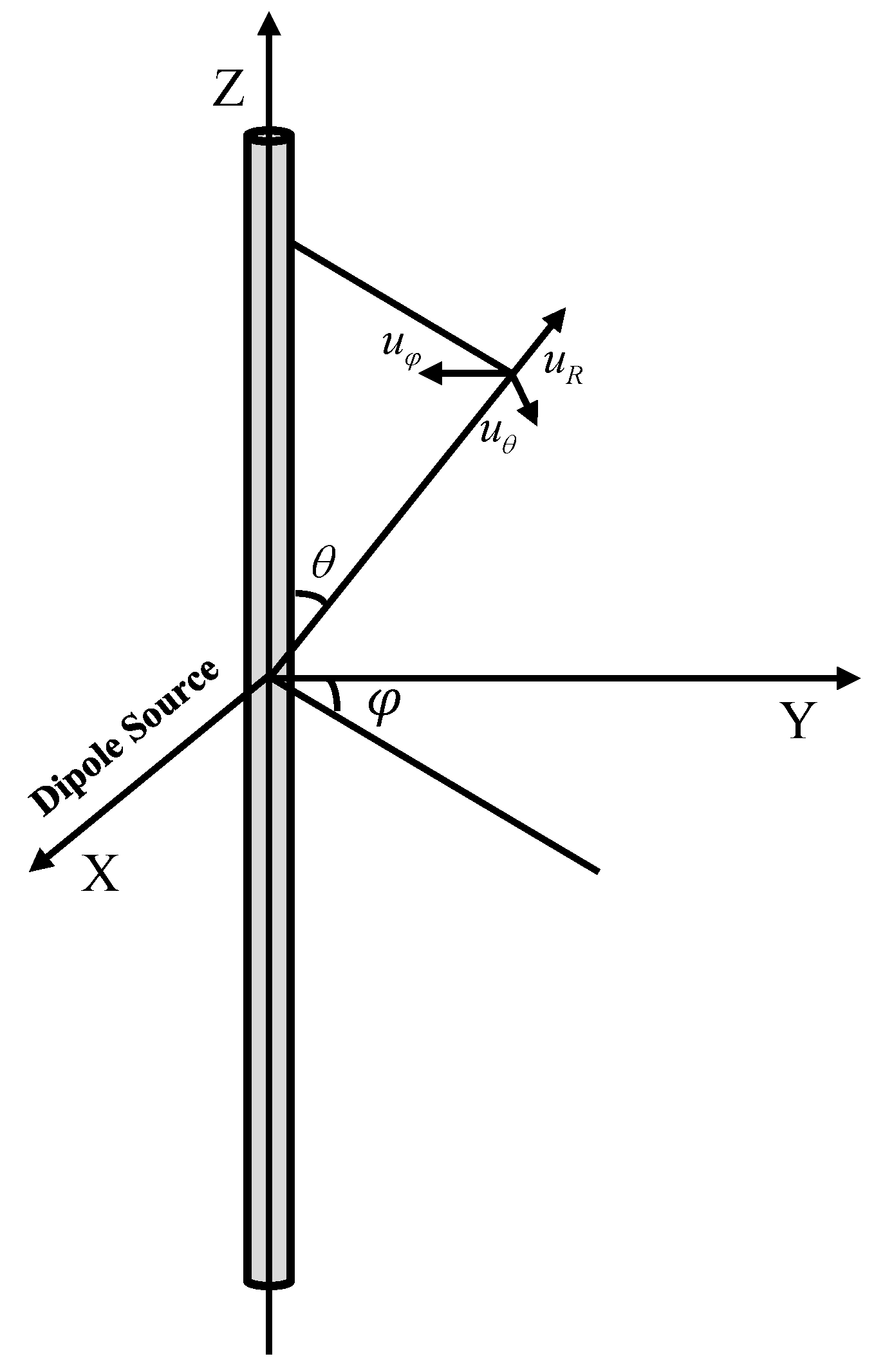
2.1. Theory of Dipole-Source Radiation in a Fluid-Filled Borehole

The model for the radiation analysis of a dipole source is illustrated in Figure 1. In this study, we only considered the shear waves radiated by the dipole source. The source is at the borehole axis, and excited in the X-direction. The displacements of the fluid in the borehole ( u f ) and the elastic wave in the formation ( u ) can be expressed by the potential function [16]:
{ u f = Φ f ( r < r 0 ) u = × ( χ z ^ ) + × × ( Γ z ^ ) ( r r 0 ) ,
where r 0 is the borehole radius; z ^ is the unit vector in the Z-axis direction; Φ f , χ , and Γ are the displacement potentials of fluid in the borehole, the SH–wave and SV–wave in the formation, respectively, and can be written as [16]:
{ Φ f ( ω ; r , z , φ ) = sin φ 4 π S ( ω ) + A ( ω , k ) I 1 ( f r ) e i k z d k ( r < r 0 ) χ ( ω ; r , z , φ ) = cos φ 4 π S ( ω ) + D ( ω , k ) K 1 ( s r ) e i k z d k ( r r 0 ) Γ ( ω ; r , z , φ ) = sin φ 4 π S ( ω ) + F ( ω , k ) K 1 ( s r ) e i k z d k ( r r 0 ) ,
where r and z are the radial distance and axis distance from the radiation field to the source; φ is the angle between the polarization direction and the radiation direction of the dipole source; S ( ω ) is the spectrum of the source; A is the amplitude coefficient of acoustic wave in the borehole; B is the amplitude coefficient of P–wave in the formation; D is the amplitude coefficient of SH–wave in the formation; F is the amplitude coefficient of SV–wave in the formation.
The amplitude coefficients of SH–wave and SV–wave in an open-hole case can be given by the following equation [20]:
[ M 11 M 12 M 13 M 14 M 21 M 22 M 23 M 24 M 31 M 32 M 33 M 34 M 41 M 42 M 43 M 44 ] × [ A B D F ] = [ u f d σ r r f d 0 0 ] .
The expressions of matrix elements in Equation (3) can be written as:
{ M 11 = I 1 ( f r 0 ) / r 0 f I 2 ( f r 0 ) M 12 = K 1 ( p r 0 ) / r 0 p K 2 ( p r 0 ) M 13 = K 1 ( s r 0 ) / r 0 M 14 = i k K 1 ( s r 0 ) / r 0 i k s K 2 ( s r 0 ) { M 21 = ρ f ω 2 I 1 ( f r 0 ) M 22 = ρ ( 2 k 2 V S 2 ω 2 ) K 1 ( p r 0 ) + 2 p ρ V S 2 K 2 ( p r 0 ) / r 0 M 23 = 2 ρ s V S 2 K 2 ( s r 0 ) / r 0 M 24 = 2 i k ρ V S 2 s 2 K 1 ( s r 0 ) + 2 i k s ρ V S 2 K 2 ( s r 0 ) / r 0 { M 31 = 0 M 32 = 2 p ρ V S 2 K 2 ( p r 0 ) M 33 = s ρ V S 2 [ s K 1 ( s r 0 ) + 2 K 2 ( s r 0 ) / r 0 ] M 34 = 2 i k s ρ V S 2 K 2 ( s r 0 ) / r 0   { M 41 = 0 M 42 = 2 i k ρ V S 2 [ K 1 ( p r 0 ) / r 0 p K 2 ( p r 0 ) ] M 43 = i k ρ V S 2 K 1 ( s r 0 ) / r 0 M 44 = ( k 2 + s 2 ) ρ V S 2 [ K 1 ( s r 0 ) / r 0 s K 2 ( s r 0 ) ] u f d = f [ K 1 ( f r 0 ) / r 0 f K 2 ( f r 0 ) ] / ( ρ f ω 2 ) , u r r f d = f K 1 ( f r 0 ) f = ( k 2 k f 2 ) 1 / 2 , p = ( k 2 ω 2 V P 2 ) 1 / 2 , s = ( k 2 ω 2 V S 2 ) 1 / 2 ,
where I n is the first kind of Variant Bessel function; K n is the second kind of Variant Bessel function; ρ f is the fluid density; ρ is the formation density; V P is the formation compressional wave velocity; V S is the formation shear wave velocity; k is the axis wave number; f is the radial wave number of the fluid; p is the radial wave number of the formation compressional wave; s is the radial wave number of the formation shear wave.
In an acoustic far detection logging survey, the waves radiated by the source are reflected in the far field. The wavelengths of the radiated waves are far lesser than the distance between the far-field point and the source. In this case, the SH–wave and SV–wave displacements expressed in Equation (2) can be obtained by the following expressions:
{ χ = D ( ω , k s 0 ) 4 π R e i ω R / V S cos φ Γ = F ( ω , k s 0 ) 4 π R e i ω R / V S sin φ ,
where k s 0 = ω cos θ 1 / V S is the far-field asymptotic solution for the axial wavenumber of shear wave; R is the distance from the source to the radiation field; θ 1 is the angle between the polarization direction of the source and the positive direction of Z-axis.
The asymptotic expressions of the displacement spectra of SH–wave and SV–wave in the far field can be obtained from Equation (5) with the relationship between the displacement and the displacement potential:
{ u φ = [ i ρ V S ω D ( ω , k s 0 ) sin θ 1 cos φ ] S ( ω ) 4 π ρ V S 2 R e i ω R / V S u θ = [ ρ ω 2 F ( ω , k s 0 ) sin θ 1 sin φ ] S ( ω ) 4 π ρ V S 2 R e i ω R / V S
where u φ is the SH–wave displacement; u θ is the SV–wave displacement.
For a given source S ( ω ) , the SH–wave and SV–wave radiated by a dipole source at any location in space can be obtained by transforming the far-field displacement spectra from frequency domain to time domain.
The contents in the parentheses of Equation (6) illustrate the radiation performance and direction of SH–wave and SV–wave of a dipole source in the far field, as expressed in Equation (7), which are dimensionless [16].
{ R S H ( ω ; θ 1 , φ ) = i ρ V S ω D ( ω , k s 0 ) sin θ 1 cos φ R S V ( ω ; θ 1 , φ ) = ρ ω 2 F ( ω , k s 0 ) sin θ 1 sin φ .
D and F can be obtained by solving Equation (3) with k = k 0 , and then radiation patterns of SH–wave and SV–wave can be obtained for any given ω from Equation (7).

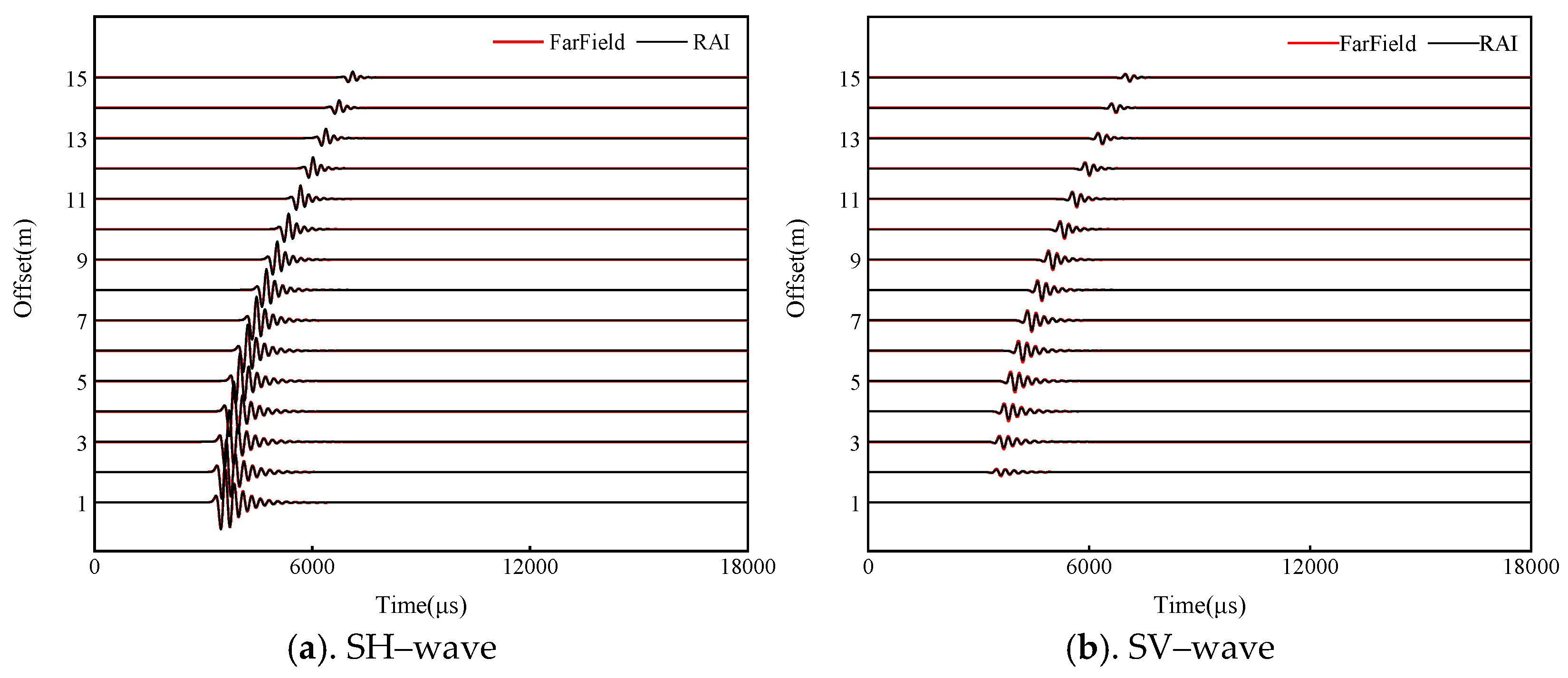
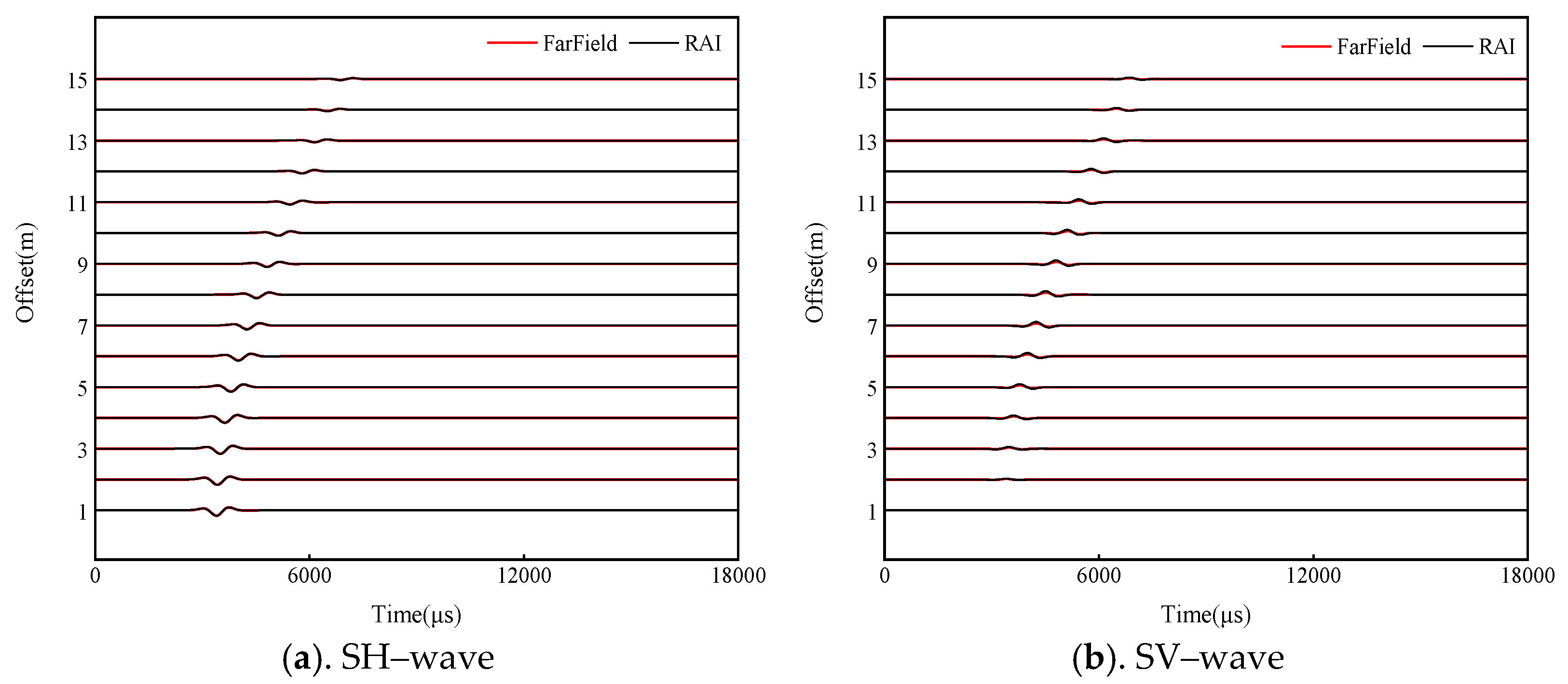
2.2. Verification of the Far-Field Asymptotic Solution

When analyzing the dipole-source radiation by the far-field asymptotic solution, it is necessary to verify the accuracy of this method in calculating the acoustic field radiated by a dipole source in the far field. In this section, the exact results of the shear wave displacements in the far field were calculated by the discrete wave number method of real-axis integration. The results were compared with those obtained by the far-field asymptotic solution. The parameters required for the calculation are shown in Table 1.
Figure 2 and Figure 3 show the comparisons of SH–wave and SV–wave displacements in the far field obtained by the exact solution (RAI) and the far-field asymptotic solution (FarField) under both low and high frequencies. The dipole source is at the borehole axis and uses the Ricker wavelet. The receiver array with 15 receivers is 5 m away from the borehole axis, and the distance between the adjacent receivers is 1 m. It can be seen from these figures that the SH–wave and SV–wave displacements in the far field obtained by the two methods are in good agreement, no matter what the source frequency is. The results indicate that the SH–wave and SV–wave displacements in the far field can be effectively calculated by the far-field asymptotic solution method.
The amplitudes of the SH–wave and SV–wave, which are closely related to the dipole-source radiation, vary with the offset in different way, as shown in Figure 2 and Figure 3. Moreover, the dipole source does not radiate SV-wave while the SH-wave radiated by the source is the strongest in the XOY plane. Accordingly, the amplitude of the SH–wave is the strongest at the offset of 1 m, while the amplitude of the SV–wave is the weakest at the offset of 1 m. Therefore, the dipole-source radiation have a significant influence on the intensity of the reflected shear waves. In this paper, the influences of formation elastic parameters, the source main frequency, and the borehole radius on the dipole-source radiation of the shear waves were analyzed in detail.

3. Results Analysis of Numerical Simulation

The influences of different factors on the dipole-source radiation of the shear waves of the dipole source were analyzed by the control variable method. The parameters of the medium formation are used for the benchmark model. The main frequency of the dipole source is 3 kHz and the borehole radius is 0.1 m.

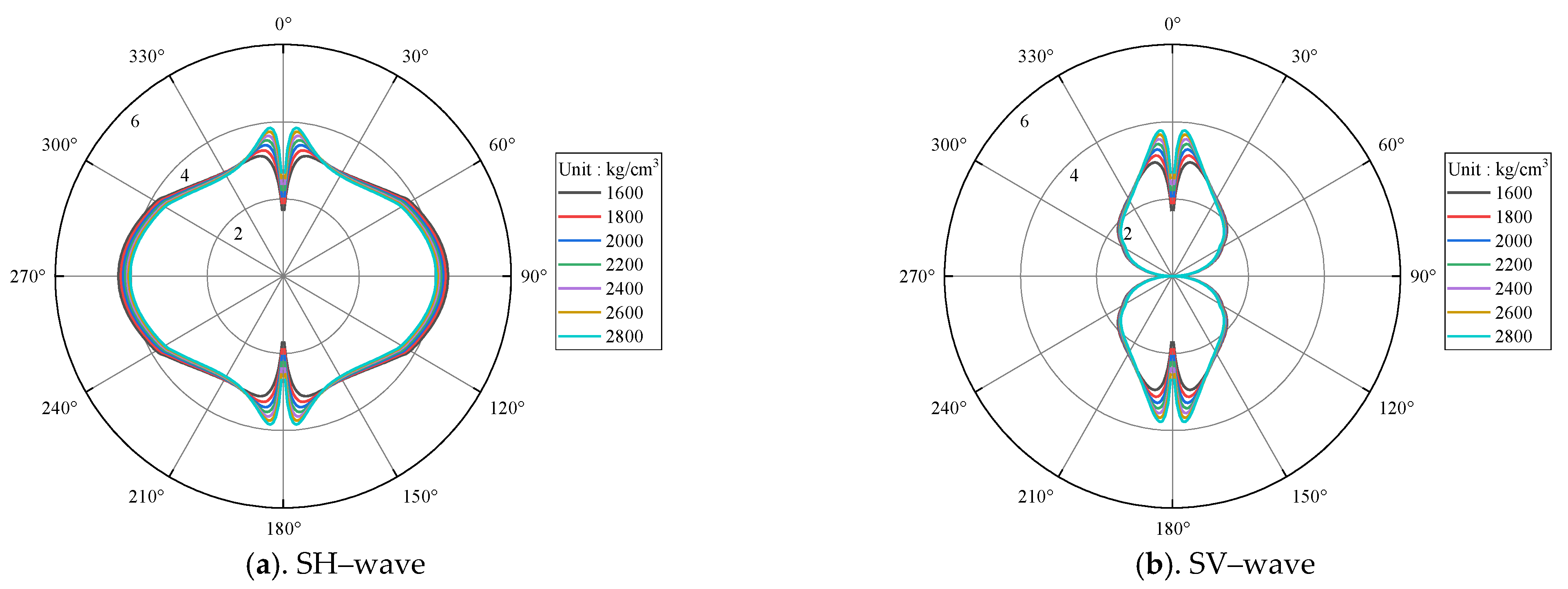
3.1. Formation Elastic Parameters

We first analyzed the influence of formation elastic parameters on the shear wave radiation characteristic of the dipole source. Figure 4 presents the radiation patterns of the shear waves radiated by the dipole source under different formation densities. The radial scale indicates the relative amplitude of SH–wave and SV–wave in the formation, which is radiated by the dipole source of unit strength. The circumferential scale indicates the angle between the radiation field point and the borehole axis. Only two typical radiation directions, SH–wave in the XOZ plane and SV–wave in the YOZ plane, are given. In other planes, the radiation patterns of SH–wave and SV–wave vary regularly in the form of sin φ and cos φ , as shown in Equation (7). It can be seen from these figures that the radiation amplitude and direction of SH–wave and SV–wave are very consistent under different formation densities, and the formation density has little influence on the dipole-source radiation of the shear waves. Similarly, as shown in Figure 5, the dipole-source radiation is also insensitive to the compressional wave velocity.
Figure 6 shows the radiation patterns of the shear waves under different shear wave velocities. The velocity changes from 3600 m / s to 800 m / s . Obviously, the radiation patterns of the shear waves vary greatly under different shear wave velocities. In fast formation ( V S > V f ), the shear wave velocity is relatively high, and the wavelength of the shear wave radiated into the formation is much greater than the borehole radius. In these cases, the modulation effect of the borehole on the dipole-source radiation of the shear waves can be neglected. In slow formation ( V S V f ), the velocity of the shear wave decreases, and the wavelength of the shear becomes shorter. In these cases, the modulation effect of the borehole on the dipole-source radiation of the shear waves strengthens. As a result, the radiation amplitude of the source decreases, and the radiation direction is obviously compressed toward the horizontal direction. It indicates that the SH–wave has a better radiation coverage and radiation amplitude in fast formation than in slow formation. Therefore, the shear wave velocity not only affects the radiation direction, but also affects the radiation amplitude of the shear waves radiated by the dipole source.

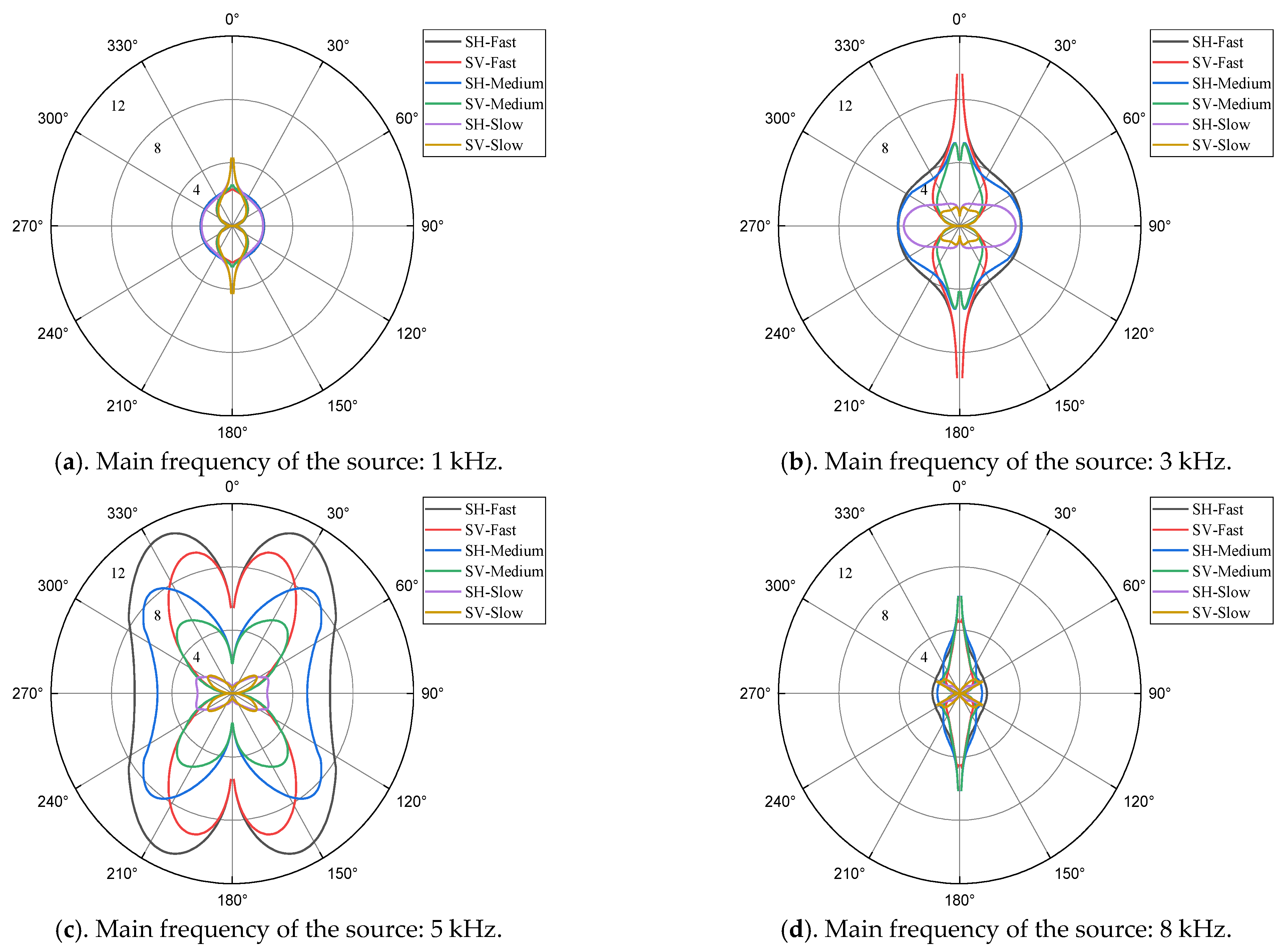
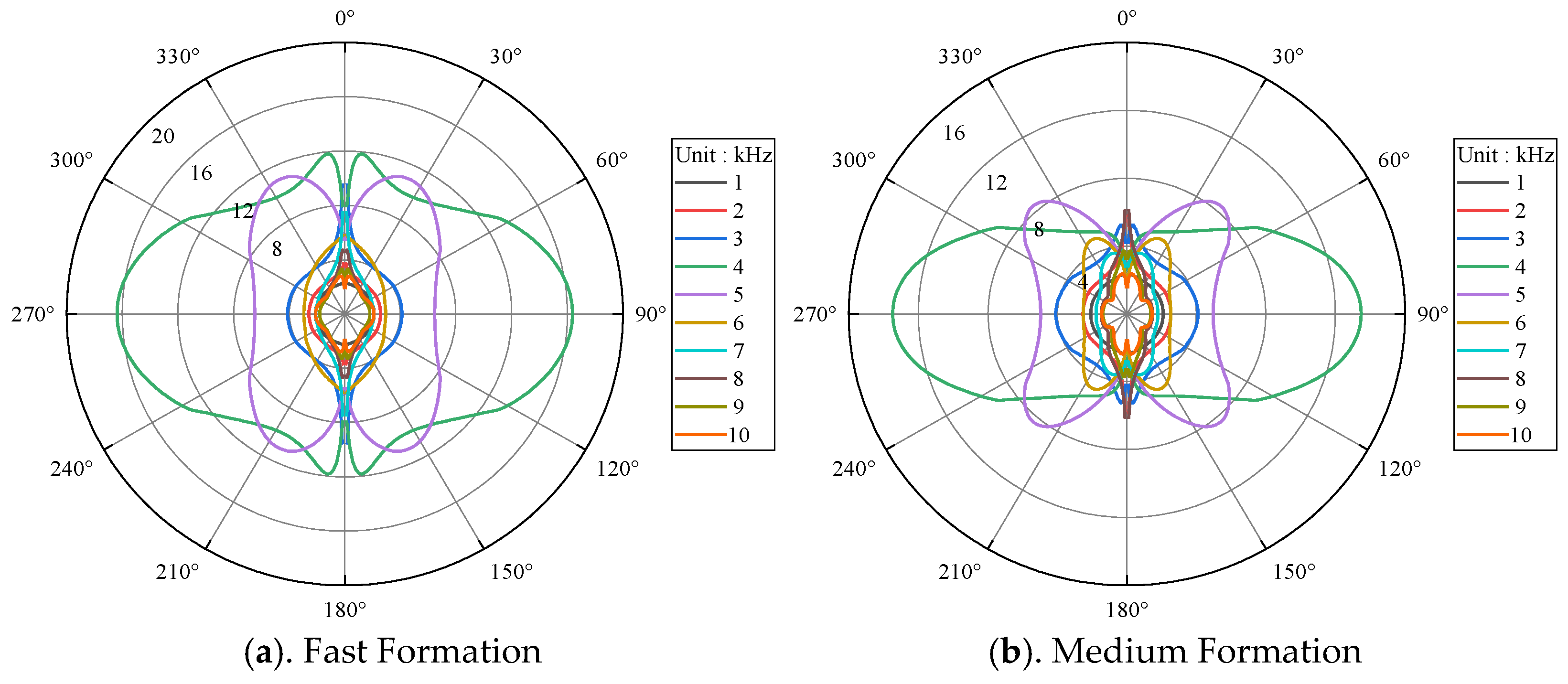
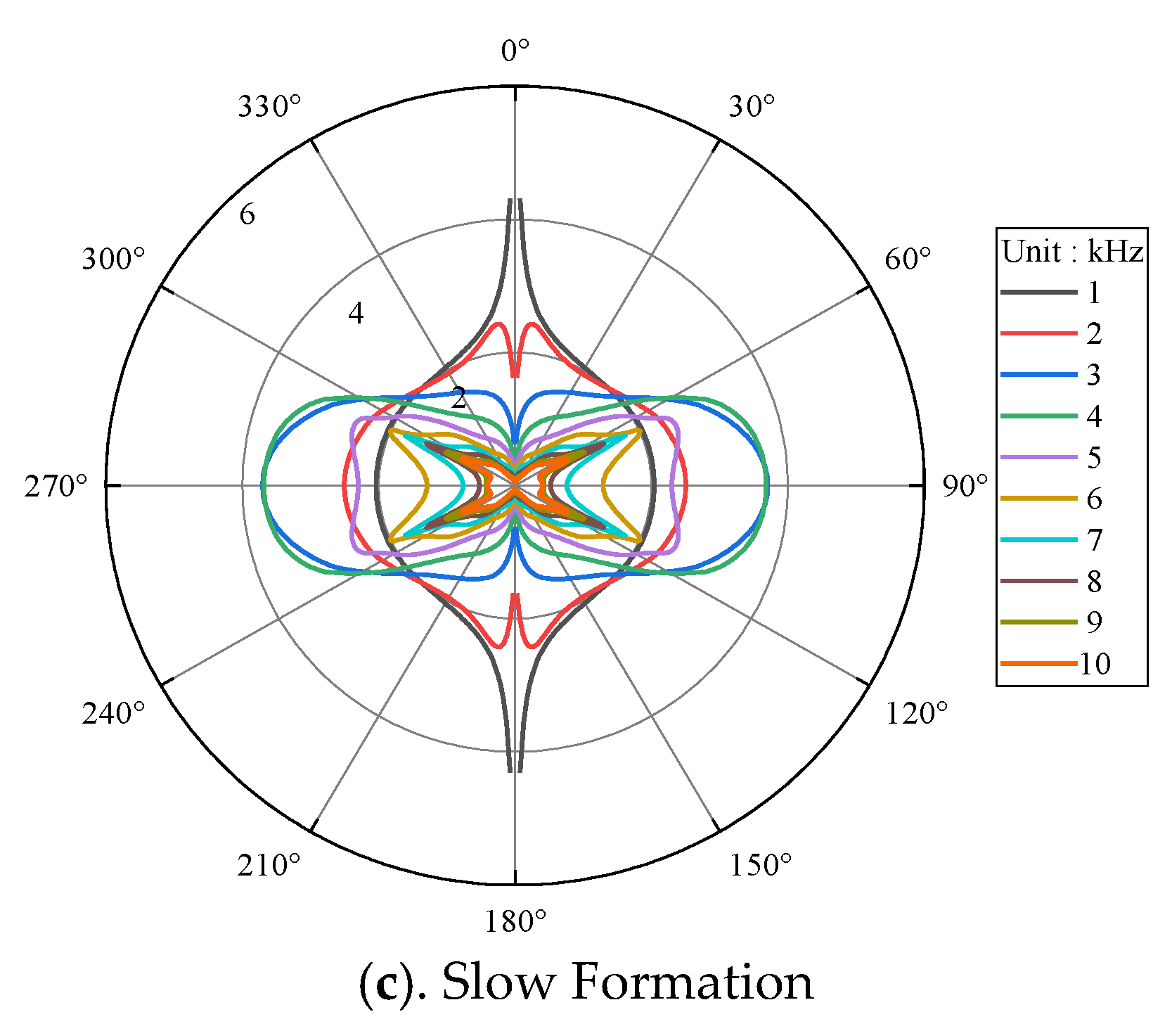
3.2. Main Frequency of the Dipole Source

The main frequency of the dipole source not only affects the radiation amplitude, but also affects the radiation direction of the source. The radiation characteristics of the shear waves under different frequencies were analyzed below.
Figure 7 demonstrates the radiation patterns of SH–wave and SV–wave under different frequencies in fast, medium, and slow formations. It can be seen from Figure 7 that the radiation amplitude and radiation direction of SH–wave and SV–wave in three formation types are very close at low frequency of the source, and the modulation effect of the borehole on the dipole-source radiation is weak in this case. When the main frequency of the source increases to 3 kHz, the wavelength of the shear wave becomes shorter and the modulation effect of the borehole on the dipole-source radiation strengthens. Under this circumstance, the radiation directions of SH–wave and SV–wave in the slow formation vary greatly, and both of them are compressed toward the horizontal direction. As the main frequency of the source increases to 5 kHz, the radiation directions of SH–wave and SV–wave in the fast and medium formations also change greatly, and are obviously compressed toward the vertical direction, which are different from those in the slow formation, as shown in Figure 7c. As the main frequency of the source increases to 8 kHz, the radiation patterns of SH–wave and SV–wave become more complex. In the slow formation, there are many extremums of the radiation amplitude of SH–wave and SV–wave in space. It is worth noting that the radiation amplitude of SH–wave is no longer constantly stronger than that of the SV–wave. In the dipole-source far detection logging, it is generally considered that the amplitude of the SH–wave is much stronger than that of the SV–wave, and the pure SH–wave can be received when the polarization direction of the dipole source is the same as the azimuth of the reflector outside the borehole. Therefore, the direction with the strongest amplitude of the reflected shear wave is the reflector azimuth. However, when the main frequency of the dipole source is high in the slow formation, the radiations of the shear waves are strongly modulated by the borehole, and the amplitude of the SH–wave is no longer stronger than that of the SV–wave. Therefore, it is difficult to distinguish the SH–wave from the SV–wave by the amplitude of the reflected shear wave at different azimuths, which may cause problems in determining the reflector azimuth.
In actual dipole-source reflected shear wave logging, SH–wave is usually used for imaging. Therefore, the radiation characteristics of SH–wave of a dipole source were mainly discussed below. Figure 8 shows the radiation patterns of the SH–wave in three formation types with the main frequency of the dipole source ranging from 1 kHz to 10 kHz, and the frequency interval is 1 kHz. It can be seen from this figure that the radiation amplitude of the SH–wave increases first and then decreases with the increase of frequency in all three formation types, and reaches the maximum value at about 4 kHz. In addition, under low frequency, the dipole source has a better radiation coverage in the vertical plane. Therefore, the dipole-source reflected shear wave logging should not choose high frequency band.

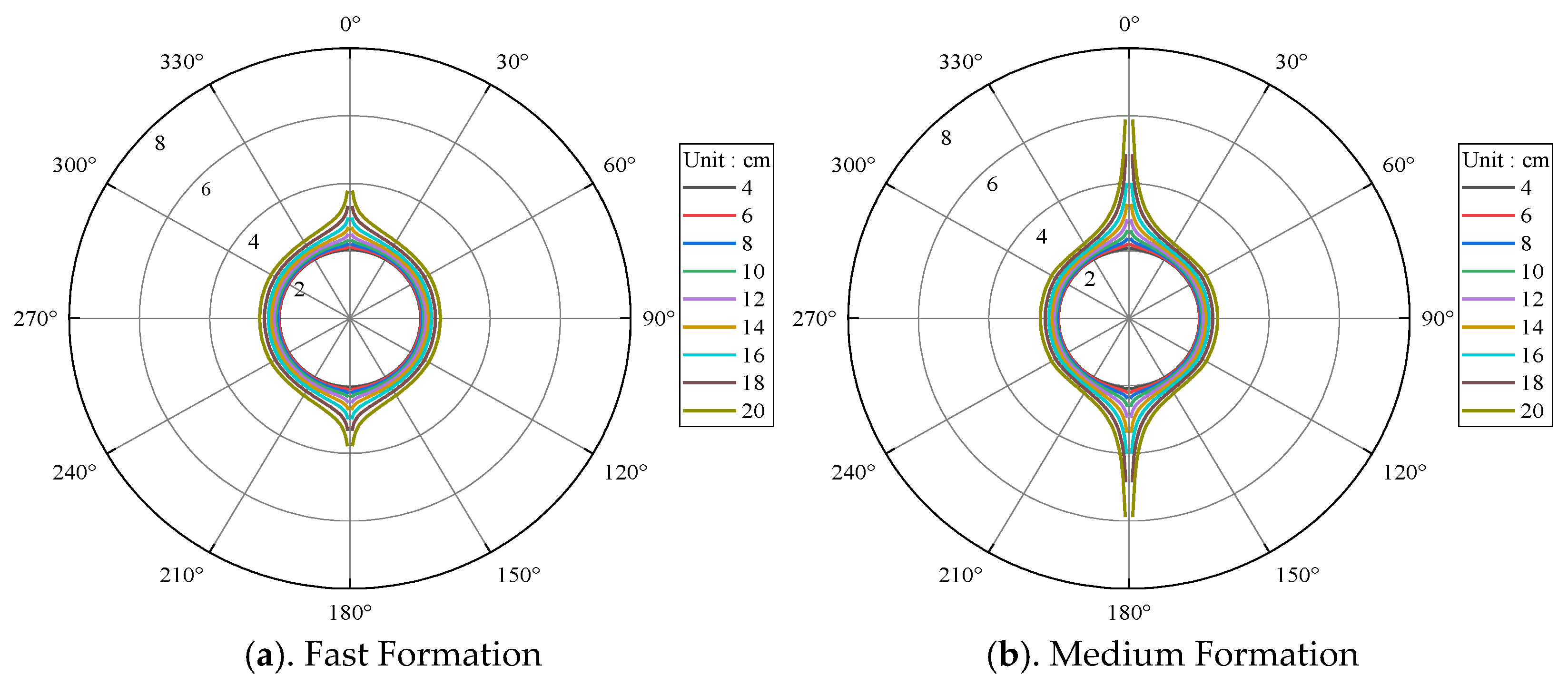
3.3. Borehole Radius

The modulation effect of the borehole on the dipole-source radiation mainly depends on the wavelength of the elastic wave and the borehole radius. The influence of the main frequency of the source on the radiation characteristics of SH–wave and SV–wave has been analyzed above. Hence in this section the influence of the borehole radius on the radiation characteristics of the shear waves was investigated in detail.
Figure 9 shows the variations of the radiation patterns of the SH–wave with the borehole radius when the main frequency of the source is 1 kHz. In this case, the wavelength of the shear wave radiated by the source is relatively long, so the borehole modulation is weak within a large borehole radius range. The dipole-source radiations under different borehole radii are almost the same in the vertical plane, and the radiation intensity increases with the increase of borehole radius. Therefore, it can be concluded that the radiation performance of the shear waves of the dipole source is better under larger borehole radius conditions, when the main frequency of the source is low.
Figure 10 shows the variations of the radiation patterns of the SH–wave with the borehole radius when the main frequency of the source is 5 kHz. It can be seen from Figure 10 that the variations of the radiation patterns of the SH–wave with the borehole radius are very similar to that with the main frequency of the source. From the previous analysis, it can be drawn that the borehole modulation on the dipole-source radiation depends on the relative size of the elastic wave wavelength and the borehole radius. The larger the ratio of the borehole radius to the wavelength, the stronger the borehole modulation on the dipole-source radiation. When the main frequency of the source remains the same, the ratio of the borehole radius to the wavelength of the shear waves radiated by the source increases with the increase of the borehole radius, and the borehole modulation on the dipole-source radiation intensifies continuously. When the borehole radius remains the same, the shear wave wavelength becomes shorter with the increase of the main frequency of the source, and the ratio of the borehole radius to the shear wave wavelength also increases. In this case, the borehole modulation on the dipole-source radiation also intensifies. Therefore, the variations of the SH–wave radiation patterns with the borehole radius are similar to that with the main frequency of the source. In addition, when the main frequency of the source is 5 kHz, the radiation amplitude of the SH–wave increases first and then decreases with the increase of borehole radius, and reaches the maximum value when the borehole radius is 8 cm, and the main lobe of the source radiation pattern is also wider. It indicates that the optimum borehole radius of the dipole-source far detection logging is 8 cm, when the main frequency of the source is 5 kHz.

4. Conclusions

The radiation of a dipole source in a fluid-filled borehole and the borehole reception of the far-field incident waves are the main factors determining the intensity of the reflected shear waves in the dipole-source reflected shear wave logging. The source radiation and the borehole reception satisfy the reciprocity principle, and the response characteristics of the two to the elastic waves are the same. In this paper, the influencing factors of the dipole-source radiation are discussed, and the influences of formation elastic parameters, source main frequency, and borehole radius on the dipole-source radiation are analyzed with the far-field asymptotic solution. The main conclusions are drawn as follows:
  • The radiation of the shear waves by a dipole-source is insensitive to formation density and compressional wave velocity, but very sensitive to shear wave velocity. The shear wave velocity of the formation not only affects the shear wave amplitude radiated to the formation by the dipole source, but also affects the amplitude of the shear waves at different positions in space.
  • The borehole modulation on the dipole-source radiation is weak at low frequency (lower than 1 kHz). However, it cannot be neglected at high frequency (higher than 3 kHz). The optimal main frequencies of the source in different formations are very close, which is good for the application of this technology under different conditions.
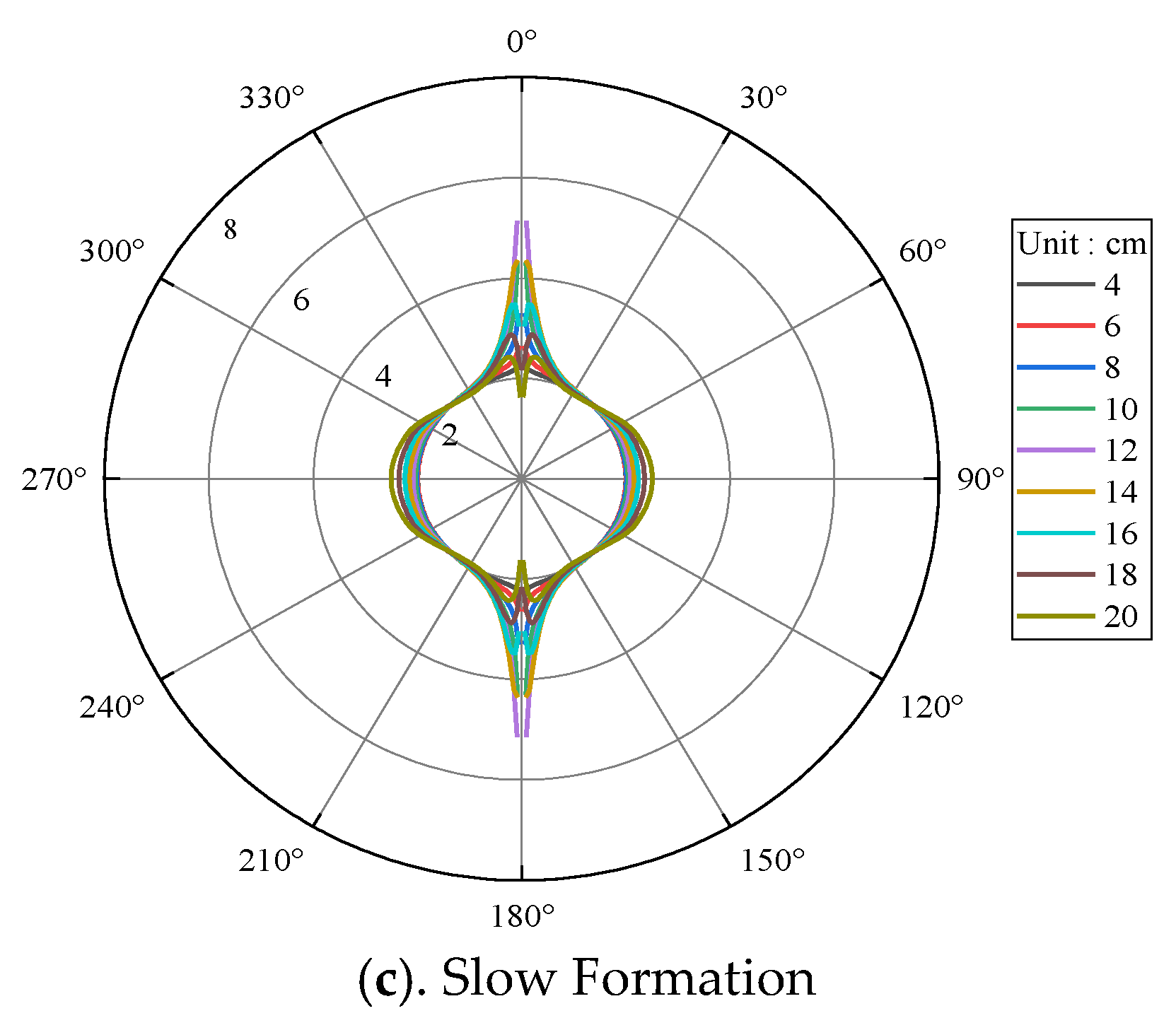
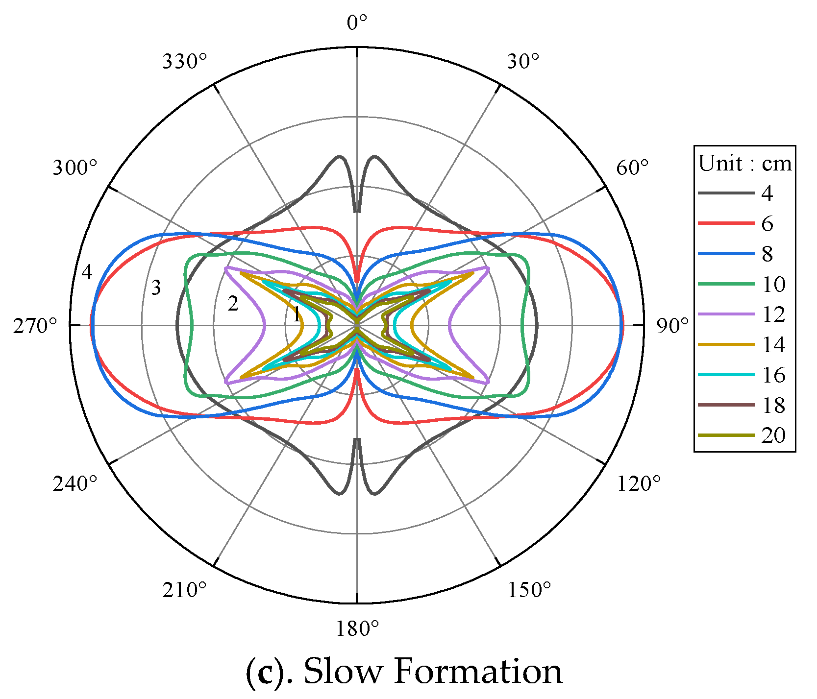
  • The borehole modulation on the dipole-source radiation depends on the relative size of the shear wave wavelength and the borehole radius. The larger the ratio of the borehole radius to the shear wave wavelength, the stronger the modulation on the dipole-source radiation. Therefore, the variations of the dipole-source radiation patterns of the shear waves with the borehole radius are similar to that with the main frequency of the source under certain conditions.

Author Contributions

Conceptualization, H.W. and C.W.; Data curation, Y.L.; Investigation, H.W. and H.F.; Methodology, H.W.; Software, S.X. and Y.Y.; Supervision, C.W.; Validation, Y.L., K.B. and X.L.; Visualization, Y.Y.; Writing—original draft, H.W.; Writing—review & editing, K.B. and X.L. All authors have read and agreed to the published version of the manuscript.

Funding

This research is financially supported by the Forward and Fundamental Technology Research Projects of CNPC (Grand No. 2021DJ3903).

Data Availability Statement

All data have been included in the manuscript.

Conflicts of Interest

The authors declare no conflict of interest.

References

  1. Hornby, B.E. Imaging of near-borehole structure using full waveform sonic data. Geophysics 1989, 54, 747–757. [Google Scholar] [CrossRef]
  2. Yamamoto, H.; Watanabe, S.; Koelman, J.M.V.; Geel, J.; Brie, A.; Fujii, K.; Coates, R. Borehole Acoustic Reflection Survey Experiments in Horizontal Wells for Accurate Well Positioning. In Proceedings of the SPE CIM International Conference on Horizontal Well Technology, Calgary, AB, Canada, 6–8 November 2000. [Google Scholar]
  3. Chai, X.Y.; Zhang, W.R.; Wang, G.Q.; Liu, J.D.; Xu, M.; Liu, D.D.; Song, C.L. Application of Remote Exploration Acoustic Reflection Imaging Logging Technique in Fractured Reservoir. Well Logging Technol. 2009, 33, 539–543. [Google Scholar]
  4. Zheng, Y.B.; Tang, X.M. Imaging near-borehole structure using acoustic logging data with pre-stack F−K migration. In Proceedings of the SEG Annual Meeting, Houston, TX, USA, 6–11 November 2005. [Google Scholar]
  5. Li, J.X.; Tao, G.; Zhang, K. Borehole sonic reflection imaging by finite difference reverse time migration. In Proceedings of the SEG Annual Meeting, Houston, TX, USA, 23–27 September 2013. [Google Scholar]
  6. Tang, X.M.; Glassman, H.; Patterson, D. Single-well acoustic imaging in anisotropic formations. Geophysics 2008, 73, 109–113. [Google Scholar] [CrossRef]
  7. Li, J.X.; Tao, G.; Kristopher, A.I. Borehole Reverse Time Migration in Anisotropic Medium. In Proceedings of the SEG Annual Meeting, New Orleans, LA, USA, 18−23 October 2015. [Google Scholar]
  8. Zhang, G. Forward Modeling and Efficient Processing Algorithms of Remote Detection Acoustic Logging. Ph.D. Thesis, Peking University, Beijing, China, 2016. [Google Scholar]
  9. Li, N.; Xiao, C.W.; Wu, L.H.; Shi, Y.J.; Wu, H.L.; Feng, Q.F.; Zhang, C.S.; Xie, B.; Zhao, T.P. The Innovation and Development of Log Evaluation for Complex Carbonate Reservoir in China. Well Logging Technol. 2014, 38, 1–10. [Google Scholar]
  10. Haldorsen, J.; Voskamp, A.; Thorsen, R.; Vissapragada, B.; Williams, S.; Fejerskov, M. Borehole Acoustic Reflection Survey for High Resolution Imaging. In Proceedings of the SEG Annual Meeting, New Orleans, LA, USA, 1−6 October 2006. [Google Scholar]
  11. Tang, X.M.; Douglas, J.P. Single-well S-wave imaging using multicomponent dipole acoustic-log data. Geophysics 2009, 74, 211–223. [Google Scholar] [CrossRef]
  12. Tang, X.M.; Patterson, D. Shear-wave imaging using cross-dipole acoustic logging tool. In Proceedings of the SEG Annual Meeting, Houston, TX, USA, 25–30 October 2009. [Google Scholar]
  13. Wei, Z.T.; Tang, X.M. Numerical simulation of radiation, reflection, and reception of elastic waves from a borehole dipole source. Geophysics 2012, 77, 253–261. [Google Scholar] [CrossRef]
  14. Cao, J.J.; Tang, X.M.; Wei, Z.T. Radiation of an acoustic dipole source in open and cased borehole with application to single-well shear-wave imaging. Chin. J. Geophys. 2014, 57, 1683–1692. [Google Scholar]
  15. Cao, J.J.; Tang, X.M.; Su, Y.D.; Wei, Z.T.; Zhuang, C.X. Radiation characteristics of the single-well imaging field in while-drilling logging using an acoustic dipole source. Chin. J. Geophys. 2016, 59, 3503–3512. [Google Scholar]
  16. Tang, X.M.; Cao, J.J.; Wei, Z.T. Radiation and reception of elastic waves from a dipole source in open and cased boreholes. J. China Univ. Pet. 2013, 37, 57–64. [Google Scholar]
  17. White, J.E. Use of reciprocity theorem for computation of low-frequency radiation patterns. Geophysics 1960, 25, 613–624. [Google Scholar] [CrossRef]
  18. Meredith, J.A. Numerical and analytical modelling of downhole seismic sources: The near and far field. Ph.D. Thesis, Massachusetts Institute of Technology, Cambridge, MA, USA, 1990. [Google Scholar]
  19. Tang, X.M.; Cao, J.J.; Wei, Z.T. Shear-wave radiation, reception, and reciprocity of a borehole dipole source: With application to modeling of shear-wave reflection survey. Geophysics 2014, 79, 43–50. [Google Scholar] [CrossRef]
  20. Cao, J.J.; Tang, X.M.; Su, Y.D.; Wei, Z.T. Radiation efficiency of a multipole acoustic source in a fluid-filled borehole. Chin. J. Geophys. 2016, 59, 757–766. [Google Scholar]
  21. Cao, J.J.; Tang, X.M.; Su, Y.D. Radiation characteristics of a multipole acoustic source in an open borehole. Tech. Acoust. 2016, 35, 487–492. [Google Scholar]
  22. Cao, J.J.; Tang, X.M.; Su, Y.D.; Lee, S.Q. Radiation characteristics of an acoustic dipole source for single-well imaging. In Proceedings of the SEG Annual Meeting, Dallas, TX, USA, 16–21 October 2016. [Google Scholar]
Figure 1. Coordinate system for the radiation analysis of a dipole source in a fluid-filled borehole.
Energies 15 06789 g001
Figure 2. Far-field displacements of SH–wave and SV–wave obtained by the exact solution and the far-field asymptotic solution with the source frequency of 3 kHz in the medium formation.
Energies 15 06789 g002
Figure 3. Far-field displacements of SH–wave and SV–wave obtained by the exact solution and the far-field asymptotic solution with the source frequency of 1 kHz in the medium formation.
Energies 15 06789 g003
Figure 4. Radiation characteristics of SH–wave and SV–wave of a dipole source under different formation densities.
Energies 15 06789 g004
Figure 5. Radiation characteristics of SH–wave and SV–wave of a dipole source under different formation compressional velocities.
Energies 15 06789 g005
Figure 6. Radiation characteristics of SH–wave and SV–wave of a dipole source under different formation shear velocities.
Energies 15 06789 g006
Figure 7. Radiation characteristics of SH–wave and SV–wave of a dipole source in different formations under different main frequencies.
Energies 15 06789 g007
Figure 8. Radiation characteristics of SH–wave of a dipole source in different formations under different main frequencies.
Energies 15 06789 g008aEnergies 15 06789 g008b
Figure 9. Radiation characteristics of SH–wave of a dipole source under different borehole radii with the main frequency of the dipole source 1 kHz.
Energies 15 06789 g009aEnergies 15 06789 g009b
Figure 10. Radiation characteristics of SH–wave of a dipole source under different borehole radii with the main frequency of the dipole source 5 kHz.
Energies 15 06789 g010aEnergies 15 06789 g010b
Table 1. Parameter values for model calculation.
V P ( m / s ) V S
( m / s )
ρ ( kg / cm 3 ) r
( m )
Fluid1500010000.1
Fast Formation622034552710-
Medium Formation360019202250-
Slow Formation280012002150-
Publisher’s Note: MDPI stays neutral with regard to jurisdictional claims in published maps and institutional affiliations.

