Abstract
Aiming at the problems of pipeline blockage and equipment wear caused by large sand production in shallow gas hydrate mining on the seabed, based on the solid-state fluidization mining method, the idea of in situ separation of natural gas hydrate is proposed, and the downhole design is based on the physical parameters of hydrate mixed slurry. For the in situ helical separator, the CFD-Fluent commercial software was used to establish an analysis model and optimize the response surface of the model. The effects of the three-stage variable-pitch helix and blades on the performance of the separation device were investigated. The simulation results and response surface optimization were conducted through experiments to verify the accuracy. The results show that the third-stage pitch has the greatest impact on the separation efficiency and pressure drop, while the first-stage pitch has the least impact. The pressure drop and separation efficiency are fully considered. After the response surface optimization, the optimal three-stage pitch is the first-stage pitch x1 = 72.227 mm, the pitch of the second stage x2 = 105 mm, and the pitch of the third stage x3 = 124.817 mm. The separation efficiency of the optimal structure is verified by experiments. Compared with the previously used fixed-pitch downhole cyclone separator, the three-stage variable pitch cyclone, the separator improves the separation efficiency from 88.29% to 97.16% while keeping the pressure drop unchanged.
1. Introduction
Natural gas hydrate is a solid ice-like substance in which methane is wrapped in water molecules under certain temperature and pressure conditions to form a cage-like structure [1,2,3]. It is an ice-like substance formed by guest molecules (such as methane) and cage-like structures called hosts [4,5]. Crystalline compounds, with large global reserves and high carbon content [6], are roughly equal to twice the total carbon content of other fossil energy sources [7]. Gas hydrates are known for their abundant energy reserves, wide distribution, shallow deposits, high energy density, and clean combustion [8,9,10], making them the most promising alternative energy sources for the future [11,12].
The downhole cyclone separator used in this paper is mainly used in the fluidized exploitation of natural gas hydrate. Aiming at the weakly cemented gas hydrate deposits in deep water and shallow layers on the seabed, Shouwei Zhou et al. proposed a solid-state fluidized green mining technology [13,14]. Its process is shown in Figure 1. After the particles are mixed with seawater, the mixed slurry obtained by crushing and fluidization passes through an in situ separation system to separate the sand contained in it [15,16,17]. The purified hydrate slurry is transported to the offshore platform by a sealed pipeline [18]. Separating and backfilling sand in situ can reduce energy loss and time cost in the mining process [19,20], reduce the risk of geological disasters caused by mining, and greatly improve mining efficiency [21]. The downhole cyclone separator is an ideal separation equipment, which has the advantages of compact structure, small volume, low cost, low energy loss, high efficiency, and good separation effect [20,22,23].
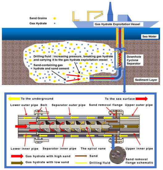
Figure 1.
The technology of exploitation and separation of natural gas hydrate.
There are no moving parts in the cyclone separator. After the mixture enters the separator, it performs helical motion under the guidance of the helical blades. The high-speed helix generates centrifugal force to stratify the phases in the mixture. For the experimental study of the cyclone separator, Li [24] using experimental approaches was employed to evaluate the performance of the notched vortex finder. They found that the new model is considered to work better than the other models. The experimental results suggest that the improved separator can remove particles greater than 3.5 µm in diameter, while the original separator can remove only particles with diameters greater than 8 µm. The experimental method has the characteristics of intuition and accuracy, but the operation is complicated, the cost is high, and it takes a long time, which is not conducive to doing multiple sets of experiments [25].
However, subject to the development of the flow field testing methods, the experimental method to study the internal flow field is costly, limited in accuracy, and time-consuming. With the rapid development of computer simulation applications in recent years, it is possible to quickly complete the accurate solution of hugely complex equations in the era of high-performance computers and become one of the important technical means to explore the characteristics of flow fields. Boyson first applied computer simulation to the study of cyclones in 1982 and used the k-ε model to perform the two-dimensional numerical calculations of an industrial cyclone. The calculation results of tangential velocity can be well combined. The experimental observation had value, but the simulation of the pulsation velocity has a large error. Although the computational fluid dynamics at that time were limited by the level of computing power, there were still many deficiencies. However, with the further optimization of computational equations and the continuous improvement of computer computing power, computational fluid dynamics became one of the important means to study the characteristics of flow fields.
To improve the separation performance of the cyclone, response surface optimization methods are widely used to improve the separation efficiency of cyclone separators. It can greatly reduce the amount of calculation. Kou [26] studies the effects of the velocity field, pressure field, and separation performance under different cone angles, which indicates that swirling intensity and residence time have an important impact on the performance of hydro cyclones. Two suitable underflow tubes were designed, which greatly improved the performance of the cyclone. Li [24] successfully investigated multi-objective structural optimization of an axial-flow-type gas-particles cyclone separator through CFD and RSM. Using four significant factors (blade tilt angle, blade axle diameter, exhaust pipe diameter, and insertion depth of exhaust pipe) they were selected and applied in the RSM. Simultaneously, numerical simulation was used to verify the accuracy of the optimized design, which indicated good performance and reliability of the RSM. To improve the separation efficiency of the downhole cyclone separator and reduce its pressure drop, it is necessary to study and improve the pitch of the helical blade of the cyclone separator.
To solve the problem of high sand content in natural gas hydrate mining, the separation efficiency and pressure drop of the downhole cyclone separators under different screw pitches were obtained by computer numerical simulation based on the solid-state fluidization mining method and the downhole in situ separation process. The optimal pitch of the helical blade under variable pitch is found by the response surface optimization method. At the same time, the previous experimental studies of others are cited and referred to, which ensures the calculation accuracy and simulation results of computer simulation and response surface optimization.
2. Methods
2.1. Model Design
The downhole cyclone separator is mainly divided into an inlet section, a variable-pitch helical split section, and an outlet section. Restricted by the underground space environment, the outer diameter of the variable-pitch separator is D = 203 mm. To ensure separation efficiency, after comprehensively considering the pressure drop and the structure size, the helical blade adopts a three-blade structure. The original structure is a fixed-pitch structure, and its pressure drop and separation efficiency are shown in Figure 2. As shown in Figure 2, the previous studies focused on the fixed pitch cyclone separator [27,28] and method of CFD simulation. The results showed that due to the low separation efficiency under the same working conditions and the same blade length, and with the decrease of the pitch, the separation efficiency is slightly improved but the pressure drop increases significantly. Because the pitch of the spiral blade of the downhole cyclone separator is constant, the pressure drop is uniform. If the pitch is too small, it is very easy to cause sand blockage, which makes the downhole swirl flow [29]. A variable pitch spiral blade cyclone separator can effectively solve this problem. The separator failed, causing economic losses, so it is no longer in use. The two-stage, variable-pitch cyclone also has the same problem, so the three-stage variable-pitch cyclone is mainly used at present. The inlet of the separator is in the form of an axial inlet and is short in size and length. The helical separation section is the main component of the structure of the downhole cyclone. The currently used variable-pitch cyclone is surrounded by variable-pitch helical blades and inner and outer walls. To improve the separation efficiency of the mixed liquid, the pitch adopts a three-stage variable pitch design, which can make the mixed liquid have a larger centrifugal force and further reduce the overall size of the cyclone separator. The outlet splitting section adopts the sleeve form.
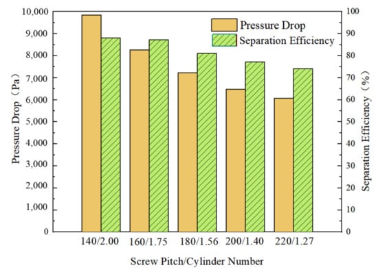
Figure 2.
Separation Efficiency and Pressure Drop of Fixed-pitch Cyclone Separator.
The drilling fluid enters the underground from the annular space around the inner pipe of the downhole cyclone separator. It then breaks the underground natural gas hydrate by jet, and then carries the natural gas hydrate back to the sea. During the working process of the variable pitch separator, the mixed liquid with a certain initial velocity enters from the inlet section and passes through the variable pitch spiral flow channel. The mixed liquid gradually changes from a linear flow to a spiral flow, and a large tangential velocity is obtained at the same time. The two phases of natural gas hydrate and sand exist in the form of cement. The downhole cyclone separator we developed has two functions. The first function is cyclone gel breaking. The density and particle size of the cement is large, so it will be subjected to great inertial force, including Coriolis force and centrifugal force. In addition, it is also subjected to the combined action of traction, gravity, buoyancy, and other forces. Therefore, the cement of natural gas hydrate and sand will have a strong rotation and revolution in the cyclone chamber. It will collide with the spiral blade and the inner wall to realize the cyclone gel breaking and to then separate the natural gas hydrate and sand. The second effect is that the particle size and density of natural gas hydrate and sand are different, so the centrifugal force is different to achieve separation. The spiral flow generates centrifugal force, which makes the solid phase with higher density flow along the outer wall of the separator. The hydrate phase with lower density flows in the inner layer of the separator. At the connection between the spiral flow channel and the outlet pipe section, the natural gas hydrate phase with lower density flows out from the inner pipe of the central branching section. The solid phase with a higher density is discharged from the outer pipe, along the outer wall of the cyclone separator. Finally it completed the separation of sand and gas hydrate separation of two phases. After separation, the gas hydrate particles are lifted to the offshore oil platform for processing. In this paper, the three-stage pitch of the three-stage variable-pitch cyclone separator is used as the input variable. The separation efficiency and pressure loss of the cyclone are the dependent variables. The structural parameters, separation efficiency, and the mathematical relationship model between underflow pressure loss then determines the best multi-parameter optimization matching scheme. The structure and principle of the downhole cyclone separator are shown in Figure 1.
2.2. Validation
The simulation methodology employed in this study has been validated against experimental data published in the literature [30]. L is the channel length of the cyclone separator, and D is the channel diameter of the cyclone separator. By establishing different L/D models for simulation analysis, the analysis method is consistent with that in this paper, and the results are compared with the experimental results obtained by Lin [30]. The split ratio Ru obtained by HSMA velocity measurement and CFD numerical simulation is shown in Figure 3. The comparison between the simulation results and results on separation efficiency is shown in Figure 4. The satisfactory agreement of the two quantities shown in Figure 3 and Figure 4, obtained from the two different methodologies, confirms the accuracy of the CFD model employed in the present study. Since the simulation is conducted in an ideal state without considering the factors such as inter-particle force and wall friction, the obtained separation efficiency is slightly larger than the experimental results. The reason the separation efficiency is lower than that of this paper is that the diameter of the central tube is large, and it is a fixed pitch cyclone separator with fewer circles.
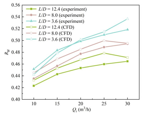
Figure 3.
Splitting Ratio of Experiment and CFD Simulation.
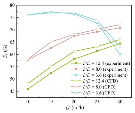
Figure 4.
Separation Efficiency of Experiment and CFD Simulation.
2.3. Numerical Simulation Method
2.3.1. The Basic Principle of the Response Surface Method
The response surface optimization method is to fit a relatively complex unknown functional relationship with a simple linear or quadratic polynomial model in a specific area analysis. Then it is to obtain a more accurate optimal solution to achieve parameter optimization. Since the second-order polynomial model has high accuracy, its form is relatively simple, and it has the characteristics of strong predictability. The second-order polynomial model is selected in this paper, and the input indicators (three-stage variable-pitch cyclone with three different pitches) serve as a function of response objectives (separation efficiency and pressure loss). The selected second-order polynomial model basis function is [31]
In the formula, y is the response target, which represents the separation efficiency and pressure loss of the downhole cyclone respectively; , is the independent design variable, which represents the structural parameters in this paper; and k is the number of design variables. This paper aims at two or three different structure parameters used for optimization research, so k = 3; is the regression equation constant; respectively, are the linear offset coefficient, second-order offset coefficient, and interaction coefficient of the regression equation.
2.3.2. Mathematical Model
- (1)
- Liquid phase control equation
The mass conservation equation is:
The momentum equation is:
The energy equation is:
In the formula, ρ1 is the density of the liquid phase, v1 is the flow velocity of the liquid phase, μ1 is the dynamic viscosity of the liquid phase, p is the pressure acting on the liquid element, and F is the volume force acting on the liquid element, u, v, ω is the velocity of three directions, E is the internal energy of liquid phase per unit mass, Ei is the internal energy of liquid phase, and Ef is the potential energy of liquid phase.
- (2)
- Control equation of particle phase
The drag force between liquid and solid natural gas hydrate is modeled in the literature [32], so the expression of the drag coefficient is:
In the formula, α1 is the volume fraction of the fluid; Res is Reynolds number; and ds is solid particle size, μm; vs. is solid particle velocity, m/s.
2.3.3. Force of Sand in the Downhole Cyclone Separator
In the downhole cyclone separator, the ratio of centrifugal acceleration to gravitational acceleration of sand is expressed by centrifugal strength I as follows:
g—acceleration of gravity, m/s2; r—swirler separator fluid domain radius, m; ut—radius r tangential velocity m/s.
Generally speaking, the size of the I value can reach hundreds or even thousands. From the above formula, it shows that the underground cyclone separator formula derivation cannot consider the role of gravity. Since the movement characteristics of sand are realized under the action of radial motion, the role of centrifugal inertia force in this process is the focus of analysis.
In the radial direction of the downhole cyclone separator, the force acting on the sand particles is very complex. However, in the case of low sand volume fraction, there are three main forces that play an important role in the separation efficiency: fluid resistance Fs, centripetal buoyancy Fb, and centrifugal inertia force Fc. The force that makes the particles move to the cylinder wall is centrifugal inertia force Fc. The expression is as follows:
d—Particle diameter m; ρ—Particle density kg/m3.
Due to the different pressure values of the particles in the radial surface, the centripetal buoyancy Fb is generated. The equation is as follows:
The relative motion between the fluid medium and the sand particles produces fluid resistance Fs, and the equation is as follows:
The relative velocity of particles to fluid in radial direction: vr
The downhole cyclone separator is mainly affected by the above three forces, so it will produce total velocity, radial velocity, tangential velocity, and axial velocity. The tangential velocity and axial velocity mainly affect the separation efficiency. The tangential velocity is a manifestation of the centrifugal force on the sand particles. The greater the tangential velocity of the sand particles, the greater the centrifugal force, indicating that it is close to the wall surface and the better the separation efficiency. The axial velocity represents the residence time of sand in the downhole cyclone separator. The larger the axial velocity, the better the processing capacity of the downhole cyclone separator and the higher the processing efficiency.
2.3.4. Parameter Settings and Boundary Conditions
The Discrete Phase model was used for the simulation calculation of drilling fluid, natural gas hydrate, and sand. Taking natural gas hydrate production wells using three-stage variable pitch cyclone separators as the research object, the inlet of the downhole cyclone separator is set as the velocity inlet. The inlet velocity is determined to be 5 m/s according to the actual working conditions. The Reynolds Stress (7 eqn) model is used in the turbulence model, and other model parameters are set by default. According to the physical property parameters of the mixed liquid in the field, the dynamic viscosity of drilling fluid was set as 1.7 mPa·s in the numerical simulation, and the density of drilling fluid is 910 kg/m3. The Discrete Phase model uses Lagrangian particle tracking. According to field data and related literature, the average particle size of sand is 90 μm [33], particle velocity consistent with fluid velocity, and particle mass flow rate determined to be 1 kg/s based on field sand production. The outlets of the inner and outer tubes are set as pressure outlets. The DPM of the inner tube is set to ‘escape’, and the DPM of the outer tube is set to ‘trap’ to facilitate the statistics and calculation of the sand separation efficiency. Uses the Discrete Phase model and Lagrangian particle tracking to make the calculated separation efficiency more accurate. The Fluent solver uses the double-precision pressure benchmark algorithm for the implicit solver to solve the steady state, the Reynolds stress equation model is used for the turbulent flow calculation, and the SIMPLEC algorithm is used for the coupling between velocity and pressure. The inner wall of the cyclone separator is set as a non-slip boundary, Conditions, momentum, turbulent kinetic energy, and turbulent dissipation rate are all set to the second-order upwind discrete format. The convergence accuracy is set to 10−6, and the wall is set to non-leakage, no-slip boundary conditions [34,35,36].
3. Results and Discussion
3.1. CCD Experimental Design and Equation Construction
The experimental design methods of response surface analysis include central composite design (CCD), Box–Behnken design (BBD), secondary saturation design, uniform design, Taguchi design, etc. The more commonly used experimental design methods are mainly CCD and BBD. The spatial point distribution of the CCD experimental design is shown in Figure 5, where 1 represents the upper level of the design factor, and −1 represents the lower level of the design factor. The advantage of the CCD experimental design is that it can better fit the response relationship between each factor and the output index. Due to the existence of the α value of the axial point, the search range of the process of obtaining the optimal solution by CCD is wider than that obtained by BBD [37]. Therefore, the CCD experimental design method is used in this paper to determine the experimental plan of the effect of operating parameters on the separation efficiency and pressure loss of the downhole gas hydrate cyclone separator. The best experimental results of the three-stage variable-pitch cyclone separator obtained by the single-factor method adopted by the research team in the previous stage were taken as the center point of this orthogonal test. The coded values are shown in Table 1.
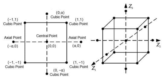
Figure 5.
Distribution of cubic, axial and central points in CCD design.

Table 1.
Three-Stage Variable Pitch CCD Test Factor Level Design.
Based on the CCD experimental design method, the three structural parameters to be optimized are used as independent variables, the number of factors is set to 3, and the α value of the axial point is 1.682. The number of dependent variables is 2, which are the separation efficiency EZ of the downhole natural gas hydrate cyclone separator and the underflow pressure drop value (pressure loss) Δp. The calculation method of underflow pressure loss is the average static pressure value on the inlet section minus the average static pressure value on the underflow outlet section. The calculation expression of separation efficiency is as follows:
In the formula, is the overflow split ratio; is the mass concentration of natural gas hydrate phase at the underflow outlet, mg/L; is the mass concentration of natural gas hydrate phase at the separator inlet, mg/L. Based on the factor levels of different operating parameters in Table 2, a total of 17 groups of CCD experimental designs were formed. According to the operating parameters of different experimental design groups, the establishment of the fluid domain model of the downhole cyclone separator was completed. After simulation analysis, the separation efficiency EZ and underflow pressure loss Δp of different test groups were calculated, and finally, the response surface test design scheme and numerical simulation results were obtained as shown in Table 2.
Table 2.
Design and Test Results of CCD.
A second-order model is used to fit the result data shown in Table 2 by a quadratic polynomial, and the regression equation between the optimized operating parameters and the separation efficiency y1 and underflow pressure loss y2 of the downhole cyclone separator can be obtained through multiple linear regression analysis. They are as follows:
3.2. Analysis of Variance
The analysis of variance method is used to test the significance of the mathematical models between the three structural parameters constructed by the response surface and the separation efficiency and pressure loss, respectively. The analysis of variance results shown in Table 3 can be obtained.
Table 3.
ANOVA Results of Regression Equations.
Table 3 shows that the regression equation between the operating parameters and the separation efficiency y1 and pressure loss y2 is p < 0.01, indicating that the functional relationships reflected by the two regression equations are significant, indicating that the upper and lower limit parameters shown in Table 1 change. Within the range, two regression equations (Equations (12) and (13)) can be used to calculate the first-stage pitch x1, the second-stage pitch x2, and the third-stage pitch x3 of the multi-parameter condition variables of the helical blade of the downhole cyclone, respectively. Separation efficiency and underflow pressure loss values are predicted.
To verify the prediction accuracy of the regression equation, the error statistical analysis is performed on Equations (12) and (13) respectively, and the error statistical analysis results shown in Table 3 can be obtained. It can be seen from Table 4 that the closer the R2 value of the correlation coefficient is to 1, the better the correlation of each factor. The larger the value of Adjuster R2 and Predicted R2 and the closer their absolute values are means that the regression model can more fully reflect the relationship between the input and output variables. The coefficient of variation is less than 10%, indicating that the test results have high accuracy and reliability. Adeq Precision is the ratio of effective signal to noise, and a value greater than 4 indicates that the model is reasonable. Statistical analysis results show that the obtained regression models are in line with the above test principles, indicating that the two models have good applicability.
Table 4.
Error Statistics Analysis Results of Regression Mode.
3.3. Optimization Results and Verification
The least squares method is used to perform the partial differential derivation of the regression equation between the constructed operating parameters and the separation efficiency. The optimal design point after the response surface optimization is obtained by calculating the structural parameter matching scheme that can maximize the separation efficiency. The calculation results show that the optimal values of the optimized operating parameters are the first pitch x1 = 72.227 mm, the second pitch x2 = 105 mm, and the third pitch x3 = 124.817 mm. The optimized helical blade of the cyclone separator is shown in Figure 6.
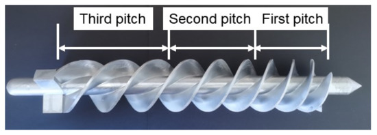
Figure 6.
Schematic diagram of the optimized helical blade of the cyclone separator.
To verify the separation performance of the optimal results obtained from the fitting equations, this paper conducts research from two aspects. Firstly, the numerical simulation method is used; that is, the model is modeled according to the optimal structural parameters obtained, and the numerical simulation analysis of the separation performance is conducted. Conversely, the optimized cyclone structure prototype was processed, and relevant laboratory tests were conducted to measure the optimized separation performance. The obtained results were compared with those predicted by the model, and at the same time compared with the initial structure separation performance to fully verify the optimization results and the reliability of the model.
3.4. Verification and Discussion of Optimization Results by CFD
The CFD simulation of the spiral blade flow channel model of the cyclone separator under different pitches is performed and the other parameters are unchanged except for the model. From the comparison of Figure 7, Figure 8 and Figure 9, it can be seen that the total velocity of sand particles is small, which is 9.26 m/s, in the swirl chamber of the cyclone separator under the well with a fixed pitch spiral blade. The maximum radial velocity of sand particles, that is, the maximum velocity of X-axis and Y-axis is less than 6 m/s. The axial velocity is evenly distributed and small, which is 8.03 m/s and therefore prone to blockage. The total speed of the variable pitch cyclone separator before optimization increased to 15.6 m/s, which was significantly improved compared with the fixed pitch cyclone separator. The maximum velocity of the X-axis and Y-axis of the sand increased significantly to 12.6 m/s and 13.5 m/s, respectively, and the axial velocity of the Z-axis increased to 8.47 m/s. The sand after the spiral blade can maintain the maximum axial velocity, which can alleviate the sand blockage to a certain extent. The total speed, X-axis maximum speed, Y-axis maximum speed, and Z-axis maximum speed of the optimized variable pitch cyclone separator increased to 15.7 m/s, 13.1 m/s, 13.7 m/s, and 8.58 m/s, respectively.
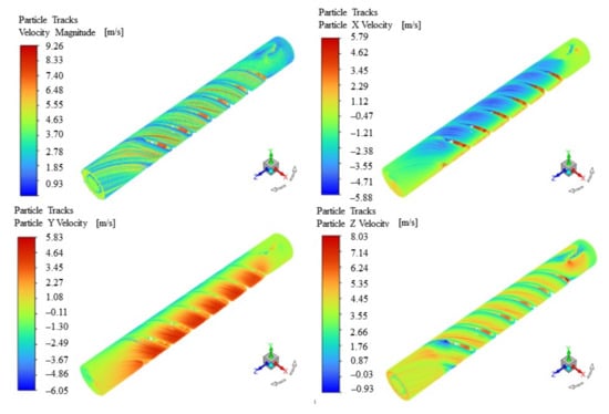
Figure 7.
Velocity distribution of sand particles in a fixed pitch cyclone separator.
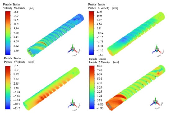
Figure 8.
Velocity distribution of sand particles in variable pitch cyclone separator before optimization.
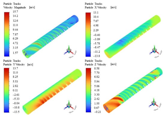
Figure 9.
Velocity distribution of sand particles in variable pitch cyclone separator after optimization.
3.5. Comparison of Separation Performance
Through the simulation and separation performance test, the comparison of the separation performance of the initial structure fixed-pitch cyclone separator and the optimized cyclone separator is shown in Figure 10. The numerical simulation results show that compared to previously used fixed pitch downhole cyclones, with an approximate pressure drop, the separation efficiency of the cyclone before and after optimization increases from 89.76% to 98.43%. By comparing the results before and after optimization, it fully shows that the optimized structural parameters can effectively improve the separation efficiency of the cyclone separator. It also proves the correctness of the regression equation obtained in this paper, which can guide the structure of the cyclone. Parameter optimization provides theoretical guidance and basis.
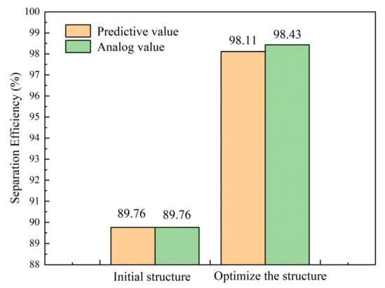
Figure 10.
Comparison of separation efficiency of downhole cyclone separator before and after optimization.
4. Conclusions
- (1)
- In this paper, the separation efficiency and pressure drop of the new three-stage variable pitch are numerically simulated by CFD-Fluent 2021 R2 software, and the optimal three-stage variable pitch size is optimized by the response surface method. Finally, the numerical simulation and the experimental results are verified. The separation efficiency of the optimized structure was verified by response surface methodology.
- (2)
- Through local sensitivity analysis, it is concluded that among the parameters of the first-stage pitch x1, the second-stage pitch x2, and the third-stage pitch x3 parameters of the variable pitch cyclone separator, the sensitivity of the influence on the sediment concentration in the bottom flow outlet is from the largest to the largest. The order to the smallest is x3 > x2 > x1.
- (3)
- It is feasible to construct the mathematical model between the structural parameters, separation efficiency, and underflow pressure loss by using the center combination design (CCD) experimental design method of the response surface. The correlation coefficient of the separation efficiency prediction model based on the second-order polynomial was 0.8979, and the correlation coefficient of the underflow pressure loss prediction model was 0.9326. The analysis of variance results verified that the model has good significance and high precision.
- (4)
- The numerical simulation is in good agreement with the model prediction results. After optimization, the separation efficiency of the cyclone structure is all above 98%, and the separation efficiency increases by more than 8%, which fully shows that the model has better performance and high feasibility.
Author Contributions
Conceptualization, M.L. and S.Z.; methodology, Q.N.; software, Q.N.; validation, Q.N.; formal analysis, M.L. and S.Z.; investigation, M.L.; resources, S.Z.; data curation, Q.N.; writing—original draft preparation, Q.N.; writing—review and editing, Q.N.; visualization, Q.N.; supervision, S.Z.; project administration, M.L.; funding acquisition, M.L. All authors have read and agreed to the published version of the manuscript.
Funding
This research received no external funding.
Institutional Review Board Statement
Not applicable.
Informed Consent Statement
Not applicable.
Data Availability Statement
Not applicable.
Conflicts of Interest
The authors declare no conflict of interest.
References
- Pan, Z.; Wu, Y.; Shang, L.; Zhou, L.; Zhang, Z. Progress in use of surfactant in nearly static conditions in natural gas hydrate formation. Front. Energy 2020, 14, 463–481. [Google Scholar] [CrossRef]
- Ruan, X.; Li, X.-S.; Xu, C.-G. A review of numerical research on gas production from natural gas hydrates in China. J. Nat. Gas Sci. Eng. 2021, 85, 103713. [Google Scholar] [CrossRef]
- Sun, H.; Chen, B.; Yang, M. Effect of multiphase flow on natural gas hydrate production in marine sediment. J. Nat. Gas Sci. Eng. 2020, 73, 103066. [Google Scholar] [CrossRef]
- Gambelli, A.M.; Tinivella, U.; Giovannetti, R.; Castellani, B.; Giustiniani, M.; Rossi, A.; Zannotti, M.; Rossi, F. Observation of the Main Natural Parameters Influencing the Formation of Gas Hydrates. Energies 2021, 14, 1803. [Google Scholar] [CrossRef]
- Guo, K.; Fan, S.; Wang, Y.; Lang, X.; Zhang, W.; Li, Y. Physical and chemical characteristics analysis of hydrate samples from northern South China sea. J. Nat. Gas Sci. Eng. 2020, 81, 103476. [Google Scholar] [CrossRef]
- Li, B.; Chen, L.-L.; Wan, Q.-C.; Han, X.; Wu, Y.-Q.; Luo, Y.-J. Experimental study of frozen gas hydrate decomposition towards gas recovery from permafrost hydrate deposits below freezing point. Fuel 2020, 280, 103476. [Google Scholar] [CrossRef]
- Roque Lima, M.D.; Santos Patricio, E.P.; Barros Junior, U.d.O.; de Assis, M.R.; Xavier, C.N.; Bufalino, L.; Trugilho, P.F.; Gherardi Hein, P.R.; Protasio, T.d.P. Logging wastes from sustainable forest management as alternative fuels for thermochemical conversion systems in Brazilian Amazon. Biomass Bioenergy 2020, 140, 105660. [Google Scholar] [CrossRef]
- Wang, J.; He, J.; Lv, X.; Ge, K.; Cheng, C.; Dong, H. Numerical analysis of the gas recovery performance in hydrate reservoirs with various parameters by stepwise depressurization. J. Pet. Sci. Eng. 2021, 203, 108670. [Google Scholar] [CrossRef]
- Zhang, H.; Bi, J.; Luo, X. Oedometer test of natural gas hydrate-bearing sands: Particle-scale simulation. J. Nat. Gas Sci. Eng. 2020, 84, 103631. [Google Scholar] [CrossRef]
- Zhang, S.-W.; Shang, L.-Y.; Zhou, L.; Lv, Z.-B. Hydrate Deposition Model and Flow Assurance Technology in Gas-Dominant Pipeline Transportation Systems: A Review. Energy Fuels 2022, 36, 1747–1775. [Google Scholar] [CrossRef]
- Jiang, L.; Xu, N.; Liu, Q.; Cheng, Z.; Liu, Y.; Zhao, J. Review of Morphology Studies on Gas Hydrate Formation for Hydrate-Based Technology. Cryst. Growth Des. 2020, 20, 8148–8161. [Google Scholar] [CrossRef]
- Sayani, J.K.S.; Lal, B.; Pedapati, S.R. Comprehensive Review on Various Gas Hydrate Modelling Techniques: Prospects and Challenges. Arch. Comput. Methods Eng. 2022, 29, 2171–2207. [Google Scholar] [CrossRef]
- Lyu, X.; Li, Q.; Ge, Y.; Zhu, J.; Zhou, S.; Fu, Q. Fundamental characteristics of gas hydrate-bearing sediments in the Shenhu area, South China Sea. Front. Energy 2021, 15, 367–373. [Google Scholar] [CrossRef]
- Sun, W.; Wei, N.; Zhao, J.; Zhou, S.; Zhang, L.; Li, Q.; Jiang, L.; Zhang, Y.; Li, H.; Xu, H.; et al. Wellbore Temperature and Pressure Field in Deep-water Drilling and the Applications in Prediction of Hydrate Formation Region. Front. Energy Res. 2021, 9, 274. [Google Scholar] [CrossRef]
- Liu, B.; Yuan, Q.; Su, K.-H.; Yang, X.; Wu, B.-C.; Sun, C.-Y.; Chen, G.-J. Experimental Simulation of the Exploitation of Natural Gas Hydrate. Energies 2012, 5, 466–493. [Google Scholar] [CrossRef]
- Xiao, J.; Wang, X.; Wang, R. Research on Factors Affecting the Optimal Exploitation of Natural Gas Resources in China. Sustainability 2016, 8, 435. [Google Scholar] [CrossRef]
- Zhou, S.; Li, Q.; Lv, X.; Fu, Q.; Zhu, J. Key issues in development of offshore natural gas hydrate. Front. Energy 2020, 14, 433–442. [Google Scholar] [CrossRef]
- Sun, Y.; Lu, X.; Guo, W. A review on simulation models for exploration and exploitation of natural gas hydrate. Arab. J. Geosci. 2014, 7, 2199–2214. [Google Scholar] [CrossRef]
- Qiu, S.; Wang, G. Effects of Reservoir Parameters on Separation Behaviors of the Spiral Separator for Purifying Natural Gas Hydrate. Energies 2020, 13, 5346. [Google Scholar] [CrossRef]
- Qiu, S.; Wang, G.; Wang, L.; Fang, X. A Downhole Hydrocyclone for the Recovery of Natural Gas Hydrates and Desanding: The CFD Simulation of the Flow Field and Separation Performance. Energies 2019, 12, 3257. [Google Scholar] [CrossRef]
- Mao, P.; Wan, Y.; Sun, J.; Li, Y.; Hu, G.; Ning, F.; Wu, N. Numerical study of gas production from fine-grained hydrate reservoirs using a multilateral horizontal well system. Appl. Energy 2021, 301, 117450. [Google Scholar] [CrossRef]
- Lan, W.; Wang, H.; Li, Y.; Feng, K.; Zhang, X.; Liu, Y.; Zhu, X.; Chen, S. Numerical and experimental investigation on a downhole gas-liquid separator for natural gas hydrate exploitation. J. Pet. Sci. Eng. 2022, 208, 109743. [Google Scholar] [CrossRef]
- Zhang, Y.; Yin, C.; Xing, L.; Liu, W.; Cao, Z. Effect of Sand Containing Conditions on Wear of Nano Ceramic Coating on Downhole Cyclone. J. Nanoelectron. Optoelectron. 2018, 13, 1514–1521. [Google Scholar] [CrossRef]
- Li, J.; Wang, T.; Zhang, L.; Chang, J.; Song, Z.; Ma, C. Multi-objective optimization of axial-flow-type gas-particle cyclone separator using response surface methodology and computational fluid dynamics. Atmos. Pollut. Res. 2020, 11, 1487–1499. [Google Scholar] [CrossRef]
- Dziubak, T. Experimental research on separation efficiency of aerosol particles in vortex tube separators with electric field. Bull. Pol. Acad. Sci.-Tech. Sci. 2020, 68, 503–516. [Google Scholar]
- Kou, J.; Chen, Y.; Wu, J. Numerical study and optimization of liquid-liquid flow in cyclone pipe. Chem. Eng. Processing-Process Intensif. 2020, 147, 107725. [Google Scholar] [CrossRef]
- Kou, J.; Zhao, Y.L. Numerical Simulation of New Axial Flow Gas-Liquid Separator. Processes 2021, 10, 64. [Google Scholar] [CrossRef]
- Zhou, F.Q.; Guo, G.S.; Xiao, P.H.; Yong, Z.; Wen, Q.B. Experimental and CFD study on effects of spiral guide vanes on cyclone performance. Adv. Powder Technol. 2018, 29, 3394–3403. [Google Scholar] [CrossRef]
- Dasar, M.; Patil, R.S. Investigations on various characteristics of novel cyclone separator with helical square fins. Sep. Sci. Technol. 2020, 55, 2994–3011. [Google Scholar] [CrossRef]
- Hai, T.L.; Yuan, H.; Hua, L.W. Study on axial-flow hydrocyclone for in-situ sand removal of natural gas hydrate in the subsea. E3S Web Conf. 2021, 245, 01050. [Google Scholar]
- Riano, B.; Molinuevo, B.; Garcia-Gonzalez, M.C. Optimization of chitosan flocculation for microalgal-bacterial biomass harvesting via response surface methodology. Ecol. Eng. 2012, 38, 110–113. [Google Scholar] [CrossRef]
- Chang, Y.L.; Ti, W.Q.; Wang, H.L.; Zhou, S.W.; Huang, Y.; Li, J.P.; Wang, G.R.; Fu, Q.; Lin, H.T.; Wu, J.W. Hydrocyclone used for in-situ sand removal of natural gas-hydrate in the subsea. Fuel 2021, 285, 119075. [Google Scholar] [CrossRef]
- Hiroko, M.; Satoshi, T.; Akio, Y.; Kazuyuki, H.; Tohoru, T.; Yoshito, G.; Tetsuro, M. Natural gas storage and transportation within gas hydrate of smaller particle: Size dependence of self-preservation phenomenon of natural gas hydrate. Chem. Eng. Sci. 2014, 118, 208–213. [Google Scholar]
- Jiang, L.; Bai, L.; Xue, P.; Peng, G.; Zhou, L. Two-Way Coupling Simulation of Solid-Liquid Two-Phase Flow and Wear Experiments in a Slurry Pump. J. Mar. Sci. Eng. 2022, 10, 57. [Google Scholar] [CrossRef]
- Li, Y.; Zeng, X.; Lv, W.; He, Z. Centrifugal pump wear for solid-liquid two-phase flows based on computational fluid dynamics-discrete element method coupling. Adv. Mech. Eng. 2020, 12, 1687814020937951. [Google Scholar] [CrossRef]
- Wang, Y.; Chen, J.; Xie, L.; Liu, H.-L.; Luo, K.-K. Combined experimental and computational investigation of the effect of coating on operation characteristics of solid-liquid two-phase flow centrifugal pump. Mod. Phys. Lett. B 2021, 35, 2150062. [Google Scholar] [CrossRef]
- Zhao, C.; Yan, Y.; Li, H.; Zhang, T.; Qiao, S. An effective gamma white spots removal method for CCD-based neutron images denoising. Fusion Eng. Des. 2020, 150, 111375. [Google Scholar] [CrossRef]


Publisher’s Note: MDPI stays neutral with regard to jurisdictional claims in published maps and institutional affiliations. |
© 2022 by the authors. Licensee MDPI, Basel, Switzerland. This article is an open access article distributed under the terms and conditions of the Creative Commons Attribution (CC BY) license (https://creativecommons.org/licenses/by/4.0/).