Abstract
The wind turbine blade is an important component for harnessing wind energy. It plays a vital role in wind turbine operation. In this work, a study was conducted to investigate the dynamic behavior of an optimal rotary wind turbine blade with a bond graph approach simulated with MATLAB/Simulink. The model is considered as a twisted Rayleigh beam which is made of several sections of the type SG6043 airfoil. This type of airfoil is suitable for low wind conditions, and each section is subjected to aerodynamic loads that are computed using the blade element momentum theory. The bond graph model was developed based on the law of conservation of mass and energy in the systems, and then the model was converted to the MATLAB/Simulink toolbox; results were validated with SG6043 airfoil data and real wind data collected from selected specific sites of Abomsa, Metehara, and Ziway areas in Ethiopia.
1. Introduction
The wind turbine is a multidisciplinary and complex system involving different engineering disciplines such as mechanical, aerodynamic, and electrical engineering. One of the essential parts of a wind turbine is the rotary blade that interacts with the wind to convert its kinetic energy into useful energy. Wind speed causes a variety of aerodynamic forces on a wind turbine blade, where the wind is the major source of aerodynamic forces on the wind turbine blade. Several works have been recently published on the impact of aerodynamic forces on wind turbine blades. For instance, Nigam et al. [1] studied the analysis of horizontal axis wind turbine blades using the computational fluid dynamics (CFD) approach. The blade was modeled and then analyzed using the NACA 634-221 airfoil profile. The blade’s lift and drag forces were estimated at various angles of attack (AOAs). The simulation results were then compared with experimental studies published in the literature. Yuqiao et al. [2] studied the dynamic response of a flexible wind turbine blade. The blade was simplified to a cantilever beam in case of shear deformation, and the effect of cross-section rotating was considered. The finite element approach was used to solve the dynamic equations of the wind turbine blade, and the designed computer program was used to compute the dynamic response. Navideh et al. [3] investigated the dynamic characteristics of a horizontal axis wind turbine (HAWT) rotor blade with a stiffener, for which the model was created and implemented as a finite element model in ABAQUS. Jokar et al. [4] concentrated on the dynamic modeling and vibration analysis of horizontal axis wind turbine (HAWT) blades with a focus on the impacts of the pre-twist, rotational rigid body motion. The dynamic behavior of the blade was derived by linearizing the produced nonlinear reduced-order model around the steady-state solution. Lamine et al. [5] proposed a dynamic model of a wind turbine with flexible blades in a grid control system with the bond graph (BG) method. Two different wind turbine models were used. The first model assumed that the blades are rigid and consist of two masses, one with a large inertia and the other with a small inertia. The second model took blade flexibility into consideration. The theory of blade element momentum was used to evaluate the aerodynamic loads. Lakhal et al. [6] proposed a dynamic model for flexible wind turbines by using the bond graph approach and developed a nonlinear model that describes the behavior of a wind turbine system by considering the flexibility of the blades, drivetrain, etc. The flexible blade was modeled based on the Euler–Bernoulli beam model and the blade element momentum (BEM) theory, and the global model was created by assembling the aerodynamic model and structural model. Recent research [7,8] demonstrated that flexible turbine blades have significant advantages over the traditional rigid blades particularly in reducing the extreme fatigue loads on large-size wind turbine blades. Further advantages reported in flexible (morphing) blade design studies are improved efficiency and service life [9,10,11], better control capability by controlling the leading and trailing edges separately [12], and optimization of material use [9,10], among other advantages.
Another study by Lakhal et al. [13] showed the efficiency of the bond graph approach to modeling the flexible wind turbine by considering the flexibility of the blades, drivetrain, and tower. The simulations of the behaviors of the different parts such as the blades and drivetrain were performed using MATLAB software with real conditions and parameters, and the obtained results were compared and approved with a classical method (Lagrange’s method). Agarwal et al. [14] proposed a bond graph model of a wind turbine blade based on the blade being modeled as a Rayleigh beam consisting of several sections subjected to aerodynamic forces estimated using the BEM theory. NACA 4415 blade profile data were included in the validity model and simulated using 20-Sim software. Khaouch et al. [15,16] suggested the dynamic study of wind turbine blades using a bond graph. The model was based on the 3D Rayleigh beam theory, which consisted of several variable sections of the airfoil NACA 4415, taking into account axial and tangential flexion and free torsion associated with aerodynamic loading. The results were validated by taking into account data from the NACA 4415 blade profile. Naima et al. [17] studied the details of bond graph wind turbine blade profile, twist, and chord change along the blade in order to assess its efficiency and blade performance. The model was tested using the 20-Sim program.
The bond graph approach was also employed by Mohammed et al. [18] to construct two-bladed wind turbine systems. The aerodynamics of the blades, drivetrain, and tower of a wind turbine were all evaluated and confirmed in the model using NACA 4415 blade profile data by using the 20-Sim program. Sanchez et al. [19] proposed a bond graph model of a wind turbine system in which the blades, hub, main bearing, main shaft, gearbox, brake, high-speed shaft, and generator linked to the network were presented. Those models neglected some specific characteristics of the complexities of blade geometry. The complete aerodynamic model was simulated and validated by using real data provided in the open literature. Gonzalez-A et al. [20] studied the dynamic performance of a sky stream wind turbine with a bond graph approach. The turbine blades were modeled by a single bond graph, and the state equation of a blade section was obtained. The obtained findings were validated and compared with the complete simulation of the turbine. Furthermore, Mohammad et al. [21] contributed to bond graph dynamic modeling and control of wind turbines by making a precise model of a blade. In this model, the aerodynamic forces were examined with real data from a wind turbine, which were used to validate the 20-Sim model.
The aim of the work reported in this article is to study the dynamic behavior of an optimal rotary wind turbine blade for local selected sites with a bond graph model. The need to conduct the study based on the wind data at specific locations is due to the wind loads transmitted to each part of the wind turbine structure being based on site variables of the real wind data at local sites. Understanding the dynamic behavior of wind turbine blades for the specific working environment is thus essential for optimizing energy output, system safety, and reliability. Furthermore, it is important to forecast the dynamic response behavior of new designs. The dynamic response change is governed by several important system properties such as stiffness and damping, which are based on operational factors such as wind speed, rotational speed, and blade pitch angle. Based on the conducted literature review, we observe that the bond graph approach to wind turbine modeling has, among others, the following main advantages:
- It uses a unified graphical language that represents power exchange in the physical domain and energy dissipation and storage phenomena in dynamic systems of any multidisciplinary systems;
- It enables the visualization of the cause-and-effect relationships (causality) prior to writing mathematical equations based on proposed models.
In the proposed model, the blade is considered as a twisted Rayleigh beam which is made up of several sections of the type SG6043 airfoil [22,23], and each section is subjected to aerodynamic loads that are computed using the BEM theory. The results of the proposed models are validated using MATLAB/Simulink with real data from selected specific sites (Abomsa, Metehara, and Ziway) [24] in Ethiopia.
The remaining part of this article is organized as follows: Section 2 briefly presents the materials and methods used in the study followed. Then, the bond graph wind turbine blade modeling techniques together with the developed aerodynamic model in MATLAB/Simulink are described in Section 3, the results of which are further discussed in Section 4. Finally, the drawn conclusions are summarized in Section 5.
2. Materials and Methods
To study the dynamic behavior of the optimal rotary wind turbine blade, specific selected sites have been proposed. To begin with, the wind turbine blade structure was considered as the Rayleigh beam model with three sections modeled with the BG approach. The blade stiffness and material dumping were included by multi-field BG elements. Next, the aerodynamic loads acting on the blade structure were also modeled with the BG method, and the geometry parameters of the wind turbine blade were analyzed and determined with the BEM method in MATLAB coding. In addition to these, the blade performance and loads were also computed by using BEM theory. The overall wind turbine blade was modeled with BG by assembling the BG model of blade structure and the BG model of aerodynamics. Finally, the overall BG of the rotary wind turbine blade model was expanded into a MATLAB/Simulink block diagram following the causalities of the bond line of blade structure and aerodynamic loads of the BG model for computation and simulation of the blade response. Real data of SG6043 airfoil type, blade geometry parameters from BEM, and real variable wind velocity at 20 m height were collected by the National Meteorological Agency (NMA) of Ethiopia for three sites (Abomsa, Metehara, and Ziway); the stiffness, material dumping, mass, mass moment of inertia, etc., were used to validate the results of proposed models.
3. Bond Graph Modeling of Wind Turbine Blade
The structural dynamic behavior of a wind turbine blade is introduced in this section, and its bond graph model is created. The blade structure is considered in the model, which is subjected to wind flow in the form of aerodynamic loads such as axial force, tangential forces and moments, the rotational speed of the rotor, and the pitch angle of the blades. This blade structure is presented based on the Rayleigh beam model, which is made up of several sections. The suggested generic structural model for blades is diagrammatically illustrated in Figure 1.
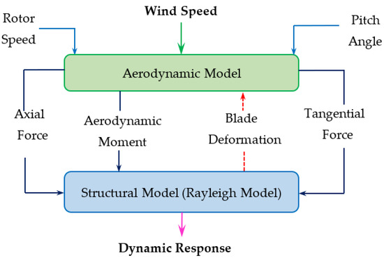
Figure 1.
Structural wind turbine blade modeling.
3.1. Blade Structural Model
Several studies on blade dynamic structural behavior based on the Rayleigh beam model have been conducted [15,16,19,25], and various approaches for re-formulating flexible beam models such as the Bernoulli–Euler model and Rayleigh model have been considered [6,13]. The Rayleigh beam model is used in this work to describe the structure of a wind turbine blade. The Rayleigh beam formulation is based on Newtonian shear force and bending moment representations. The formulation assumes that the four different displacements are considered to store potential energy in the beam segment, end displacements, and rotations [26]. The blade is considered to be a twisted beam divided into n finite segments, as illustrated in Figure 2a. Each of the segments is subjected to wind flow efforts shown in Figure 2b, while in the bond graph formulation, the structure of the blade is made using C-field and R-field elements (Figure 2c), which represent the structural stiffness and damping between the centers of gravity of adjacent ith beam elements, respectively [14,15,16,19]. The ith beam element is influenced by translational displacements wi and wi+1 and rotational displacements ϕi and ϕi+1 at both ends of the ith element, respectively.
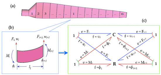
Figure 2.
(a) n blade sections; (b) loads applied on ith element; (c) C- and R-field bond graph of ith element.
The flow variables in the four parts of the C-field and R-field are the corresponding linear and rotational velocities. The effort variables are the aerodynamic forces Fi and Fi+1 and bending moments Mi and Mi+1 [26]. Thus, the generalized force and bending moment due to flexure (in a dynamic state) are given in Equation (1).
Ki is the flexural stiffness of the ith element, which depends on flexural rigidity (EI) and blade element length (li) as given in Equation (2), and Ri is the dumping matrix which depends on the flexural stiffness of the element and dumping coefficient (μ), i.e., Ri = μ[Ki].
where Li = li − 1 + li/2 and I = Ii − 1 + Ii.
In this work, the whole blade structure is divided into three sections. The length of each element is li which is subjected to the source of efforts (Se). Therefore, three blade elements are assembled to model the finite length (L) of the blade. The nodal masses and moment of inertias are included as lumped inertias at 1-junctions representing nodal linear and angular velocities, respectively. Likewise, the external damping to linear and rotational motions is represented as lumped resistances at respective 1-junctions. The nodal inertias and lumped resistances can be represented by using an I-field and R-field respectively [27]. Figure 3 illustrates the structural bond graph model of a three-sectional wind turbine blade which is subjected to aerodynamic forces.
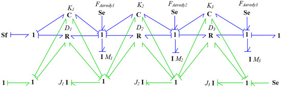
Figure 3.
Bond graph model of wind turbine blade structure with three sections.
3.2. Aerodynamics Model
The wind turbine aerodynamic model is a crucial phase in the design process. Its purpose is to compute the aerodynamic loads applied on the blades’ structure from wind speed, rotor rotational speed, and blade pitch angle by using the BEM method [14,15,16,27,28,29]. BEM is the combination of blade element theory and momentum theory, which has been discussed in further detail in [27,30]. The blade element method considers that the blade is divided into N elements that are defined by radius, chord length, twist angle, and airfoil. In the blade element theory, the aerodynamic loads acting on each element are computed using the drag and lift coefficient of the airfoil [28,31,32]. The aerodynamic (lift and drag) forces applied to the ith blade elements are separated into axial Fni and tangential Fti. In the aerodynamic model, a mechanism to convert wind flow into aerodynamic loads must be sought; i.e., a flow must be converted into efforts. A modulated gyrator is used to achieve this objective. The aerodynamic loads with a gyrator element on the ith section can be expressed as in Equations (3) and (4).
where, represents the air density, wind velocity, local chord, element length, gyrator modulus, normal tangential force lift coefficient, and normal tangential force drag coefficient, respectively. Here, the following force coefficients normal to the rotor plane, , and parallel to the rotor plane, , are used:
The inflow angle , tip loss factor Fi, axial induction , and tangential induction factor are as given in Equations (7)–(10), respectively.
where Zi is defined as follows:
The thrust coefficient CTi is given by Equation (12).
The relations given in Equations (3)–(12) were implemented using the MGY-element of the bond graph, with wind flow (MSf source) converted into aerodynamic forces as illustrated in Figure 4. The individual bond graph models’ blade structural and aerodynamic loads were presented previously in Section 3.1 and here in this section (Section 3.2); they are assembled as shown in Figure 5.
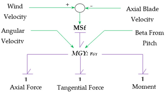
Figure 4.
Bond graph aerodynamic model.
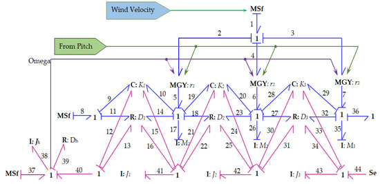
Figure 5.
Overall bond graph modeling of wind turbine blade with subjected loads. The bond graph elements are sequentially numbered (1–44).
3.3. MATLAB/Simulink Wind Turbine Blade Modeling
MATLAB/Simulink [33] is widely used in both industrial and academic research areas. Simulink is a very well-developed software whose simulations are interactive, so one can change variables on the fly and observe what happens immediately [34]. The bond graph approach, which was created with MATLAB/Simulink, has two goals: (1) to analyze the system using bond graphs and (2) to develop the system equations in symbolic form [35]. This method combines MATLAB/simulation skills with the bond graph’s modeling capabilities. In this work, the bond graph of the rotary wind turbine blade model was developed, and the causal bond graph model of the wind turbine blade in Figure 5 was expanded into a MATLAB/Simulink block diagram (as shown in Figure 6) to determine dynamic responses of the system.
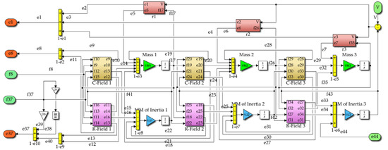
Figure 6.
Blade structural model including aerodynamic loads in MATLAB/Simulink.
Figure 7 shows the internal subsystem of the C-field of ith section which can be developed by combining the equation of the C-bond graph element with the stiffness matrix of Equation (2). The aerodynamic loads exerted on blade structure and the gyrator ratio (ri) of modulated gyrator elements can be determined from Figure 8 with the input of parameters obtained from BEM results and SG6043 airfoil data and real wind data collected from selected sites. The MATLAB/Simulink block diagram is also shown in Figure 8, and it contains different subsystems such as subsystems of C- and R-field and subsystems of the modulated gyrator elements of each of the three sections.
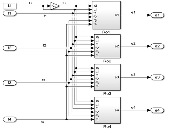
Figure 7.
The C-field bond graph ith element expanded to MATLAB/Simulink.
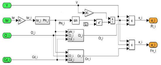
Figure 8.
Aerodynamic load model in MATLAB/Simulink.
4. Discussion of Results
In this work, the dynamic behavior of an optimal rotary wind turbine blade for local selected sites (Abomsa, Metehara, and Ziway in Ethiopia) [23,24] is studied with a bond graph approach and simulated with MATLAB/Simulink. The wind turbine blade structure with three sections and the aerodynamic loads exerted on each wind turbine blade section were modeled with the bond graph method, and the overall bond graph model of the wind turbine blade was obtained by linking the bond graph models of the blade structure and aerodynamic loads. The mathematical equations given in Equations (3)–(12) were implemented using the MGY-element of the bond graph, with the flow of wind speed (MSf source) converted into aerodynamic loads (Se source). The causal bond graph model of the wind turbine blade with aerodynamic loads was extended into the MATLAB/Simulink toolbox as shown in Figure 6 and simulated. Before starting the simulation, there are many input parameters needed for the simulation of a wind turbine blade modeled in MATLAB/Simulink toolbox. Such parameters are airfoil type and its data, geometrical parameters, wind flow data, stiffness, dumping matrix, mass, mass moment of inertia, and gyrator ratio.
In this model, the rotary blades are aerodynamically designed based on the Selig and Giguere [22] airfoil type SG6043 airfoil for low Reynolds numbers (Re) that operate in low regional wind speed. Cm, Cl, and Cd of SG6043 airfoil data were evaluated with Re of 2.3 × 10⁵, 2.5 × 10⁵, and 2.9 × 10⁵ for the selected sites of Abomsa, Metehara, and Ziway, respectively, as illustrated in Figure 9.
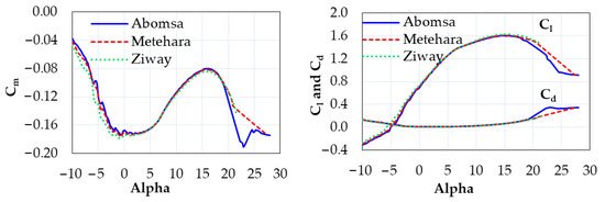
Figure 9.
The Cm, Cl, and Cd of SG6043 data for Abomsa, Metehara, and Ziway.
The geometrical parameters of wind turbine blade structure were also analyzed and determined with the BEM method in MATLAB coding using an iterative process as illustrated in Figure 10. According to the flow diagram in Figure 10, each local axial and tangential induction factor, angle of attack, blade tip loss factor, thrust coefficient, and power coefficient of the blade for each section of the blade’s span were converged after many iterations by the developed MATALB code. Some conditions were assumed at the beginning to estimate the initial value of the axial induction factor; then, the inflow angle was estimated. Following that, the axial and tangential induction factors were calculated, and the new value was used for the next cycle. This iterative process was repeated until the induction factors reached their final values [14,18,35]. For all selected sites, the rotary blade lengths of 10.74 m, 7.34 m, and 6.34 m with three blades were determined based on site data of Abomsa, Metehara, and Ziway, respectively. Based on the blade lengths of three sites, the local chords, twist angle distributions, and non-dimensional coefficients of performance CP of three blades for three sites were computed.
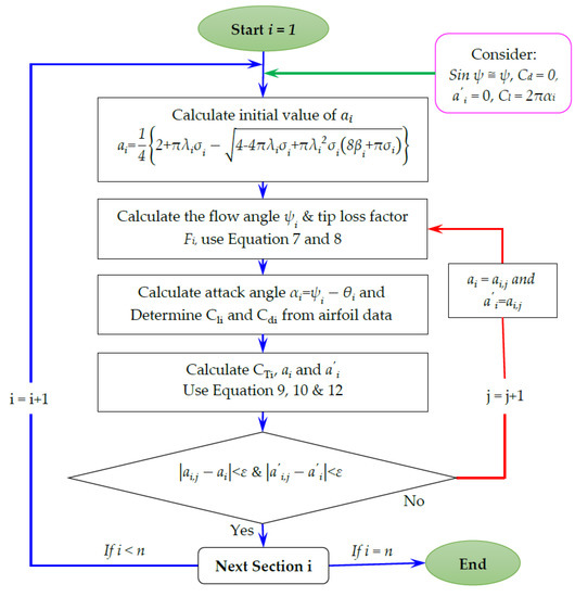
Figure 10.
The code flow diagram and steps involved in stage of BEM.
Figure 11 shows the chord distributions of wind turbine blades for the specific local sites of Abomsa, Metehara, and Ziway. As can be seen, the chords of the three blades are slightly different along radial distribution from site to site because the size of each site blade depends on the available wind data for each site. The maximum chord values of 1.415, 0.966, and 0.755 exist at twist angles of 26.049, 26.041, and 24.866 for Abomsa, Metehara, and Ziway, respectively.
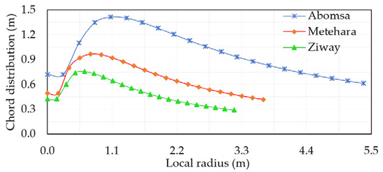
Figure 11.
Comparison of chord distribution of three specific local sites.
Figure 12 shows the twist angle distribution of blades for the three specific local sites. It can be seen that the twists all increase from the root to the tip of the blade, but they vary from site to site based on local tip speed ratios and attack angles of the blades of the three local sites.
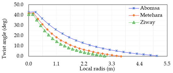
Figure 12.
Comparison of twist distribution of three specific local sites.
The distributions of the power coefficients of blades for three specific sites are illustrated in Figure 13. As can be observed from Figure 13, the maximum coefficient of performance values of CP,i are 0.4478, 0.4587, and 0.4627 at the maximum tip speed ratios (λi) of 3.0, 3.5, and 4.0 for the three sites Abomsa, Metehara, and Ziway, respectively. The Betz limit, or theoretical maximum value of Cp, is 0.596 at around a tip speed of 7. The maximum feasible Cp in practical designs is less than 0.5. The deviation from standard values is acceptable, and it is preferable to the value shown in [19] (around 0.33).
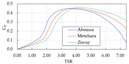
Figure 13.
Curve of CP,i vs. λi of rotor blades for three selected sites.
Figure 14 demonstrates the sites’ wind speed data variation simulated with respect to time for the three sites at 20 m height. The wind speeds varied from 0.5 to 7.9 m/s, 1.5 to 7.3 m/s, and 1.0 to 8.2 m/s at Abomsa, Metehara, and Ziway, respectively. The wind data used as input for these simulations were collected by the National Meteorological Agency (NMA) of Ethiopia at 10 m heights. The collected wind speeds at 10 m height are extrapolated to 20 m height because data were collected at a limited height (10 m), and if actual rotors of the wind turbines (wind turbine hub location) are placed, more than 10 m height is also considered. The extrapolated wind profile for all sites is simulated as input of the systems.
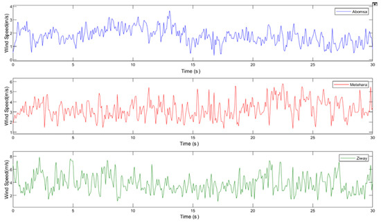
Figure 14.
Wind speed profiles of three selected sites.
Based on the variations of wind speed data of the three sites shown in Figure 14, the aerodynamic loads (normal and tangential forces) acting on the wind turbine blade structure have been determined. This computation was conducted by proving inputs from the geometry parameters obtained from BEM results, SG6043 airfoil type data, variable wind data at 20 m height, and the parameters in Table 1, Table 2 and Table 3 for wind turbine blade modeled with the MATLAB/Simulink toolbox in shown Figure 8.

Table 1.
Input parameters of the modeled blade (Abomsa site).
Table 2.
Input parameters of the modeled blade (Metehara site).
Table 3.
Input parameters of the modeled blade (Ziway site).
The tangential and normal aerodynamic loads and dynamic response of wind turbine blade behavior for three selected sites with time series were obtained from simulation, as illustrated in Figure 15, Figure 16 and Figure 17, respectively. Figure 15 and Figure 16 show that the tangential and normal aerodynamic loads exerted on the blade structure vary as the site wind data vary with time and vary from site to site. According to both figures, the maximum subjected tangential loads of 32.87 kN, 66.33 kN, and 80.21 kN and the maximum subjected normal loads of 15.12 kN, 18.03 kN, and 14.82 kN were recorded for Abomsa, Metehara, and Ziway, respectively. They reached maximum values at the maximum site wind speed value in the time series.
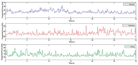
Figure 15.
Tangential force acting on wind turbine blade for three selected sites.

Figure 16.
Normal force acting on wind turbine blade for three selected sites.
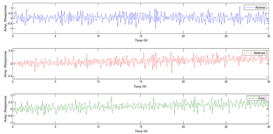
Figure 17.
Dynamic response of wind turbine blade for three selected sites.
In Figure 17, the simulated dynamic response of wind turbine blade behaviors with variable wind speeds for three selected sites is presented. Based on the variable wind speeds of 0.5–7.9 m/s, 1.5–7.3 m/s, and 1.0–8.2 m/s for Abomsa, Metehara, and Ziway, respectively, which applied to systems, the obtained dynamic response for three site blades varied with time. The minimum to maximum amplitude responses of the proposed specific selected site blades varied from −1.0 to 1.0, −0.5 to 0.5, and −1.0 to 1.0 for Abomsa, Metehara, and Ziway, respectively.
5. Conclusions
The dynamic behavior of optimal rotary wind turbine blades for specific local selected sites (Abomsa, Metehara, and Ziway in Ethiopia) was investigated with a bond graph approach and simulated with MATLAB/Simulink. In this work:
- The wind turbine blade structure with aerodynamic loaded was modeled with bond graph techniques and the causal bond graph for the modeled blade was expanded into the MATLAB/Simulink toolbox and simulated.
- The simulation results were validated with data of SG6043 airfoil type and specific variables for selected sites of wind data at 20 m height collected from Abomsa, Metehara, and Ziway sites in Ethiopia by the National Meteorological Agency (NMA) of Ethiopia.
- The geometrical parameters of the wind turbine blade were also analyzed and determined using the BEM method via MATLAB coding in an iterative process. The local axial and tangential induction factors, angles of attack, blade tip loss factors, thrust coefficients, and power coefficients of blades for each section of the blade’s span were converged by the developed MATLAB code.
- Based on the conducted study, the maximum coefficient of performance CP,i values of 0.4478, 0.4587, and 0.4627 are obtained at the maximum tip speed ratio λi values of 3.0, 3.5, and 4.0, resulting in rotors sizes (diameters) of 10.74 m, 7.34 m, and 6.34 m for the three sites Abomsa, Metehara, and Ziway, respectively.
- The dynamic response of wind turbine blade behaviors and the tangential and normal aerodynamic loads exerted on the blade were simulated and presented based on variable wind speeds of three sites. With variable wind speeds of 0.5–7.9 m/s, 1.5–7.3 m/s, and 1.0–8.2 m/s for three sites are inserted into systems, the dynamic response and the tangential and normal aerodynamic loads exerted on the blade for three site blades varying with the times were obtained, and 32.87 kN and 66.33 kN, 80.21 kN and 15.12 kN, and 18.03 kN and 14.82 kN are the maximum tangential and normal loads exerted on the blades of Abomsa, Metehara, and Ziway, respectively.
In conclusion, though the study was conducted based on the wind data of three specific locations, the approach can be customized for other locations with different weather conditions and documented wind data. The selected locations, however, must have the wind data over a period. In addition, the structural model of the wind turbine blade in the current study is proposed based on a two-dimensional Rayleigh beam model. Future work in the same direction will focus on the analysis of the dynamic behavior of flexible blades with a 3D Rayleigh beam model considering the deformation of the axial extension and the pitching moment. The possibility of extending this procedure to a complete model of a wind turbine that describes the behavior of the essential elements of the system will also be explored.
Author Contributions
Conceptualization, A.M. and B.S.; methodology, A.M. and B.S.; software, A.M.; validation, B.S. and H.G.L.; formal analysis, A.M.; investigation, A.M.; resources, B.S. and H.G.L.; data curation, B.S.; writing—original draft preparation, A.M.; writing—review and editing, B.S. and H.G.L.; visualization, A.M. and H.G.L.; supervision, H.G.L. and B.S.; project administration, B.S.; funding acquisition, B.S. All authors have read and agreed to the published version of the manuscript.
Funding
This research received no external funding.
Institutional Review Board Statement
Not applicable.
Data Availability Statement
Not applicable.
Acknowledgments
Authors wish to thank Addis Ababa Science and Technology University (AASTU) for providing financial support for the PhD study of the first author. The field (site) data obtained from the National Meteorological Agency (NMA) of Ethiopia are highly acknowledged.
Conflicts of Interest
The authors declare no conflict of interest.
References
- Nigam, P.K.; Nitin, T.; Pradhan, M.K. Analysis of horizontal axis wind turbine blade using CFD. Int. J. Eng. Sci. Technol. 2017, 9, 46–60. [Google Scholar] [CrossRef]
- Yuqiao, Z.; Rongzhen, Z.; Hong, L. Dynamic Response of Flexible Wind Turbine Blade. Telkomnika 2013, 11, 7052–7057. [Google Scholar]
- Navadeh, N.; Goroshko, I.; Zhuk, Y.; Etminan, M.F.; Soleiman, F.A. Finite Element Analysis of Wind Turbine Blade Vibrations. Vibration 2021, 4, 20. [Google Scholar] [CrossRef]
- Jokar, H.; Mahzoon, M.; Vatankhah, R. Nonlinear dynamic characteristics of horizontal-axis wind turbine blades including pre-twist. Ocean. Eng. 2022, 256, 111441. [Google Scholar] [CrossRef]
- Lamine, C.H.; Jean, Y.D.; Genevieve, D.T.; Frederic, C. Dynamic Model of a Flexible Blade Wind Turbine in an Electrical Grid Control Structure. In Proceedings of the 4th International Conference on Integrated Modeling and Analysis in Applied Control and Automation, Fes, Morocco, 13–15 October 2011. [Google Scholar]
- Lakhal, Y.; Baghli, F.Z.; El Bakkali, L. Dynamic Modeling for flexible wind turbine by the Bond Graph method. In Proceedings of the 22ème Congrès Français de Mécanique, Lyon, France, 24–28 August 2015. [Google Scholar]
- Castillo, A.D.; Jauregui-Correa, J.C.; Herbert, F.; Castillo-Villar, K.; Franco, J.A.; Hernandez-Escobedo, Q.; Perea-Moreno, A.-J.; Alcayde, A. The Effect of a Flexible Blade for Load Alleviation in Wind Turbines. Energies 2021, 14, 4988. [Google Scholar] [CrossRef]
- Bernhammer, L.O.; Van Kuik, G.A.M.; Breuker, R.D. Fatigue and Extreme Load Reduction of Wind Turbine Components Using Smart Rotors. J. Wind. Eng. Ind. Aerodyn. 2016, 154, 84–95. [Google Scholar] [CrossRef]
- Lachenal, X.; Daynes, S.; Weaver, P.M. Review of Morphing Concepts and Materials for Wind Turbine Blade Applications. Wind Energy 2013, 16, 283–307. [Google Scholar] [CrossRef]
- Alejandro Franco, J.; Carlos Jauregui, J.; Carbajal, A.; Toledano-Ayala, M. Shape Morphing Mechanism for Improving Wind Turbines Performance. J. Energy Resour. Technol. 2017, 139, 051214. [Google Scholar] [CrossRef]
- MacPhee, D.W.; Beyene, A. Performance Analysis of a Small Wind Turbine Equipped with Flexible Blades. Renew. Energy 2019, 132, 497–508. [Google Scholar] [CrossRef]
- Cognet, V.; Courrech du Pont, S.; Dobrev, I.; Massouh, F.; Thiria, B. Bioinspired turbine blades offer new perspectives for wind energy. Proc. R. Soc. A 2017, 473, 0726. [Google Scholar] [CrossRef]
- Lakhal, Y.; Baghli, F.Z.; Bakkal, L.E. The efficiency of Bond Graph approach for a flexible wind turbine modeling. J. Eng. Sci. Technol. 2017, 12, 2990–3010. [Google Scholar]
- Agarwal, S.; Chalal, L.; Dauphin-Tanguy, G.; Guillaud, X. Bond Graph Model of Wind Turbine Blade. IFAC Proc. 2012, 45, 409–414. [Google Scholar] [CrossRef]
- Zakaria, K.; Mustapha, Z.; Mustapha, A.; Nourreeddine, K.; Mustapha, M. Dynamic study of a wind turbine blade using bond graph. IOSR J. Mech. Civ. Eng. 2017, 14, 55–63. [Google Scholar]
- Zakaria, K.; Mustapha, Z.; Jamaa, B.; Nourreeddine, K.; Mustapha, M. Mechatronic modeling of a 750-kW fixed-speed wind energy conversion system using the Bond Graph Approach. ISA Trans. 2016, 65, 418–436. [Google Scholar]
- Naima, J.; Mohammed, R.; Beniassa, E.F. Prediction of horizontal axis wind turbine rotor performance: Bond Graph Approach. E3S Web Conf. 2018, 51, 01005. [Google Scholar]
- Mohammed, A.; Lemu, H.G. Wind turbine system modelling using Bond Graph method. In Advanced Manufacturing and Automation; Springer: Singapore, 2019; pp. 95–105. [Google Scholar]
- Sanchez, R.; Medina, A. Wind turbine model simulation: A bond graph approach. Simul. Model. Pract. Theory 2014, 41, 28–45. [Google Scholar] [CrossRef]
- Gonzalez-A, G.; Barrera-G, N.; Ayala, G.; Aaron-P, J.; Alvarado-Z, D. Dynamic performance of a Skystream wind turbine: A bond graph approach. Cogent Eng. 2019, 6, 1916–2331. [Google Scholar] [CrossRef]
- Mohammad, M.; Alizera, Y.; Mohammad, H.R. Bond Graph dynamic modeling and control of wind turbine. In Proceedings of the 2nd International Conference on Electrical, Computer, Mechanical and Mechatronics Engineering (ICE2015), Istanbul, Turkey, 27–28 August 2015. [Google Scholar]
- Gigueŕe, P.M.S.; Selig, M.S. New Airfoils for small horizontal, axis wind turbines. J. Sol. Energy Eng. 1998, 120, 108–114. [Google Scholar] [CrossRef]
- Mohammed, A.; Lemu, H.G.; Sirahbizu, B. Determining optimum rotary blade design for wind-powered water-pumping systems for local selected sites. Stroj. Vestn. J. Mech. Eng. 2021, 67, 214–222. [Google Scholar] [CrossRef]
- Mohammed, A.; Lemu, H.G.; Sirahbizu, B. Statistical analysis of Ethiopian wind power potential at selected sites. In Advances of Science and Technology. ICAST 2020; Delele, M.A., Bitew, M.A., Beyene, A.A., Fanta, S.W., Ali, A.N., Eds.; Lecture Notes of the Institute for Computer Sciences, Social Informatics and Telecommunications Engineering; Springer Nature: Berlin/Heidelberg, Germany, 2021; Volume 385, pp. 370–381. [Google Scholar]
- Hansen, M.O.L.; Sorensen, J.N.; Voutsinas, S.; Sorensen, N.; Madsen, H.A. State of the art in wind turbine aerodynamics and aeroelasticity. Prog. Aerosp. Sci. 2006, 42, 285–330. [Google Scholar] [CrossRef]
- Rochdi, M.; Arun, K.S.; Pushparaj, M.P.; Belkacem, O.B. Intelligent Mechatronic Systems: Modeling, Control and Diagnosis; Springer-Verlag: London, UK, 2013; ISBN 978–1-4471–4627–8. [Google Scholar] [CrossRef]
- Mukherjee, A.; Karmakar, R.; Samantaray, A.K. Bond Graph in Modeling, Simulation and Fault Identification; CRC Press: Boca Raton, FL, USA, 2006; ISBN 981-88237-96-5. [Google Scholar]
- Khalil, Y.; Tenghiri, L.; Abdi, F.; Bentamy, A. Efficiency of a small wind turbine using BEM and CF. IOP Conf. Series Earth Environ. Sci. 2018, 161, 012028. [Google Scholar] [CrossRef]
- Moriartry, P.J.; Hansen, A.C. Aerodynamic Theory Manual; NREL TP-500–36881; National Renewable Energy Laboratory: Golden, CO, USA, 2005. [Google Scholar]
- Mathworks Inc. Available online: www.mathworks.com (accessed on 1 August 2022).
- Deepak, J.; Chandan, R.; Doddanna, K. Design & Structural Analysis of a Small Wind Turbine Blade for Operation at Low Wind Speed. IRJET 2017, 4, 2188–2191. [Google Scholar]
- Supreeth, R.; Arokkiaswamy, A.; Nagarjun, J.R.; Prajwal, H.P.; Sudhanva, M. Geometrical Design of a Rotor Blade for a Small-Scale Horizontal Axis Wind Turbine. IJRTE 2019, 8, 2277–3878. [Google Scholar] [CrossRef]
- Amod, C.U.; Tusharkant, M.; Umanand, L. Bond graph simulation and symbolic extraction toolbox in Matlab/Simulink. J. Indian Inst. Sci. 2006, 86, 45–68. [Google Scholar]
- Patrik, S.; Darina, H.; Miloslav, Y.; Alexander, G. Simulation of electrical system using Bond Graph and Matlab/Simulink. Procedia Eng. 2012, 48, 656–664. [Google Scholar]
- Kyoungboo, Y. Geometry Design Optimization of a Wind Turbine Blade Considering Effects on Aerodynamic Performance by Linearization. Energies 2020, 13, 2320. [Google Scholar] [CrossRef]
Publisher’s Note: MDPI stays neutral with regard to jurisdictional claims in published maps and institutional affiliations. |
© 2022 by the authors. Licensee MDPI, Basel, Switzerland. This article is an open access article distributed under the terms and conditions of the Creative Commons Attribution (CC BY) license (https://creativecommons.org/licenses/by/4.0/).