Article

Life Test Optimization for Gas Turbine Engine Based on Life Cycle Information Support and Modeling †

by
Sagit Valeev
1,2,* and
Natalya Kondratyeva
1,2
1
Department of Computer Science and Robotics, Ufa State Aviation Technical University, Ufa 450000, Russia
2
Department of Information Technologies and Mathematics, Sochi State University, Sochi 354008, Russia
*
Author to whom correspondence should be addressed.
This paper is an extended version of Kondratyeva, N.; Valeev, S. Fatigue Test Optimization for the Aircraft Engine Based on the Life Cycle Information Support and Modeling. In Proceedings of the 6th International Conference on Industrial Engineering (ICIE 2020), Sochi, Russia, 18–22 May 2020; Lecture Notes in Mechanical Engineering; Radionov, A.A., Gasiyarov, V.R., Eds.; Springer: Cham, Switzerland, 2021, pp. 410–418. https://doi.org/10.1007/978-3-030-54817-9_48.
Energies 2022, 15(19), 6874; https://doi.org/10.3390/en15196874
Submission received: 17 August 2022 / Revised: 13 September 2022 / Accepted: 16 September 2022 / Published: 20 September 2022

Abstract

:
The task of choosing the modes and duration of life tests of complex technical objects, such as aircraft engines, is a complex and difficult-to-formalize task. Experimental optimization of the parameters of life tests of complex technical objects is costly in terms of material and time resources, which makes such an approach to the choice of test parameters practically difficult. The problem of life test optimization for gas turbine engines on the basis of the engine life cycle information support and statistical modeling is discussed. Within the framework of the research, the features of the optimization of life tests based on simulation modeling of the life cycle of gas turbine engines were studied. The criterion of the efficiency of the life tests was introduced, and this characterized the predicted effect (technical and economic) of the operation of a batch of engines, the reliability of which was confirmed by life tests; a method of complex optimization of resource tests in the life cycle system was developed. An objective function was formed for the complex optimization of life tests based on life cycle simulation. The principles of formation and refinement of the simulation model of the life cycle for the optimization of life tests were determined. A simulation model of the main stages of the life cycle of an auxiliary gas turbine engine was developed. A study was performed on the influence of the quality of the production of “critical” engine elements, the system of engine acceptance and shipment, as well as the effect of a range of parameters of the engine loading mode on the efficiency of the life tests of an auxiliary gas turbine engine. The optimal parameters of periodic life tests of an auxiliary gas turbine engine were determined by simulation modeling in the life cycle system, which made it possible to increase the equivalence of tests by several times and reduce their duration in comparison with the program of serial tests.

1. Introduction

Life tests are carried out to determine or confirm the reliability and durability (service life) of a complex technical object and, in some cases, to analyze the reliability of the object [1,2].
Life tests within the paradigm of the life cycle (LC) of a technical object are mandatory and regulated by various standards [3,4]. Life tests are divided into accelerated and long tests [5]. It is obvious that the reliability of the assessment of engine reliability parameters and, as a result, the effect (technical and economic) of their operation depends on the volume, modes, and duration of the tests [6,7].
The criterion for the effectiveness of serial life tests of gas turbine engines is the equality of the accumulated damage of critical elements of an aircraft engine in the cycles of operation and life tests [8,9]. The choice of life test parameters is determined on the basis of one generalized or several main operating cycles [10,11]. The nomenclature of cycles is set by the stakeholders [12,13].
The choice and justification of the program of life testing of aircraft products belong to the class of complex and difficult-to-formalize tasks [14,15]. A variety of factors affect the efficiency of the results of the life tests and the time- and cost-optimization of testing programs; the combinatorial nature of this problem makes it difficult to find the optimal solution [16,17]. This is due to the multi-mode nature of the operation of gas turbine engines, the long life cycle, resource limitations depending on the class of tasks being solved, and stringent requirements for the reliability of aviation gas turbine engines [18,19]. The effectiveness of the results of life tests is determined by their reliability in checking the quality of the tested products, the fulfillment of equivalence conditions, the optimal duration of tests, and the optimization of economic efficiency during operation [20,21].
Experimental optimization of life testing programs requires enormous material and time costs, which makes such an approach to justifying tests practically unacceptable [22,23]. Existing methods for constructing test programs are not always effective in terms of ensuring the adequacy of the bench and operating conditions [24]. Therefore, it is important to search for effective methods for selecting the parameters of life tests, which make it possible to increase the reliability of the assessment of the operational reliability and service life of gas turbine engines with minimal time and material costs [25,26].
In this case, due to the complex structure of tests in the life cycle system and the complexity of a complete formalization of this structure, the only possible tool is simulation modeling, which combines the advantages of analytical and statistical methods [27,28].
The justification of the parameters of the life tests of gas turbine engines using life cycle simulation is the actual task. Simulation modeling is a contemporary tool for the research on and optimization of technical systems and has been successfully used in various industries, including aviation and engine building [29,30].
In this regard, it seems relevant to study the features of the use of simulation modeling when choosing the optimal parameters of life tests.
Simulating the life cycle (LC) of a gas turbine engine (GTE) is a modern trend. For instance, it is urgent for assessing the efficiency criterion of a fatigue test in the framework of the GTE LC. A GTE is a clear example of a complex technical system consisting of several thousands of different parts and complicated components. The GTE conditions during a test are a given set of operation modes characterized by the various working parameters, measured at given time intervals with a duration of several seconds to several minutes [31,32].
In the framework of modern information technologies, different information on the economic factors at various stages of the GTE LC can be collected. The possible volume of data collected at all stages of the GTE LC is measured by terabytes or, in some cases, petabytes. Therefore, an actual task is to process these data to design the predictive models at the stage of GTE testing [33,34].
There are many limiting factors in the creation of an effective simulation model of the GTE LC applied for the selection of optimal life test parameters. One of these factors is the difficulty of assessing the efficiency criterion of the life test in the framework of the GTE LC. The source of this problem is the necessity of preprocessing the large volumes of heterogeneous data that are collected at different stages of the GTE LC (see Figure 1) [35,36].
The different data and knowledge flow in the data acquisition system are presented in Figure 1, where DB1 and DB2 are the integrated databases; KB2 is the knowledge base; D1 is the preliminary GTE characteristics description; D2, D3, D4, and D5 are necessary data for the GTE design process, production process, testing, and operation stages; K1 is the GTE knowledge obtained during operation; K2 is the verification of GTE test parameters; K3 is the verification of GTE parameters; K4 is the reclamation requirements control. Thus, the application of BigData technologies is a suitable modern solution for storing processes and analytics of the GTE LC characteristics performance [36,37].

2. Problem Definition

Under the complex efficiency of life tests of gas turbine engines, we will understand their equivalence to loading in operation in conjunction with obtaining an indirect economic effect of reducing the duration of tests and optimizing engine loading modes in tests. It is supposed that this will increase the efficiency of GTE life tests by applying the modeling results of the GTE LC when choosing test parameters. A complex criterion of the effectiveness of the capital basic investments, the different annual operating costs, the profit from the GTE during the operation modes, the cost of GTE operation and reclamation, GTE durability, and other factors can serve as complex criteria for estimating the efficiency of GTE life tests (see Figure 2).
The total GTE life test efficiency ELT is the function of the costs in all stages of the LC from the results of the requirement analysis to the possible reclamation stage (ZDES, ZDEV, ZDT, ZPR, ZPT1, ZPT2, ZOP, ZREP, and ZREC) (see Figure 2). Additional costs caused by the risks of incorrect life test parameters can be also taken into account (ZR.DEV, ZR.PR, and ZR.OP). The LC model training and its enhancements can reduce the possible risk levels and associated additional costs. The LC model training’s success depends on the implementation of data collected at different LC stages of the given GTE together with the data from similar GTEs’ statistical data.
In general, the total cost spectrum (see Figure 2) is the cost that has reflected the consumption of different kinds of used resources, from the starting stage of the research and the development of the GTE until the completion stage or reclamation. The usability of the applied criterion of life test efficiency becomes more valuable step by step as the GTE goes through the LC stages and the obtained information on the engine becomes more detailed.
To define the optimal characteristics of the life test of the GTE in order to provide the efficiency of the engine LC, several main steps are required:
1.
To define the efficiency criteria of the GTE life tests.
2.
To choose the main parameters of the GTE LC that will be applied in the GTE model.
3.
To choose simulation software and design a GTE model of the LC.
4.
To implement the series of computer-based simulations within the defined plan of experiments.
5.
To find the optimal values of the life test parameters based on the LC simulation.
The key point of the study is that simulation modeling was used to evaluate the integrated efficiency criterion of the LC of a gas turbine engine, which allowed the choice of the optimal parameters of the life tests. The integral economic efficiency of the life cycle of the GTE includes the component ELT, which depends on a set of parameters: reliability, durability, maintainability, etc.
The solution to a given task requires acquiring data at all stages of the LC, preprocessing heterogeneous data flows, and storing large volumes of these data. The key applied data, knowledge bases, and data flows are presented in Figure 2. Here, DB1 and DB2 are integrated databases storing large amounts of data on the GTE LC, i.e., damageability, life spending, maintenance, and economic parameters; KB2 is the knowledge base storing extracted knowledge on the LC stages and control flow data; D1 is the preliminary GTE characteristics description; D2, D3, D4, and D5 are data applied for the GTE requirement analysis, design process, developmental and periodic testing processes, production, and operation procedures; K1 and K5 represent the rules of the GTE operation; K2 is the validation of the test parameters; K3 is the validation of the maintenance parameters; and K4 represents the reclamation requirements control data.

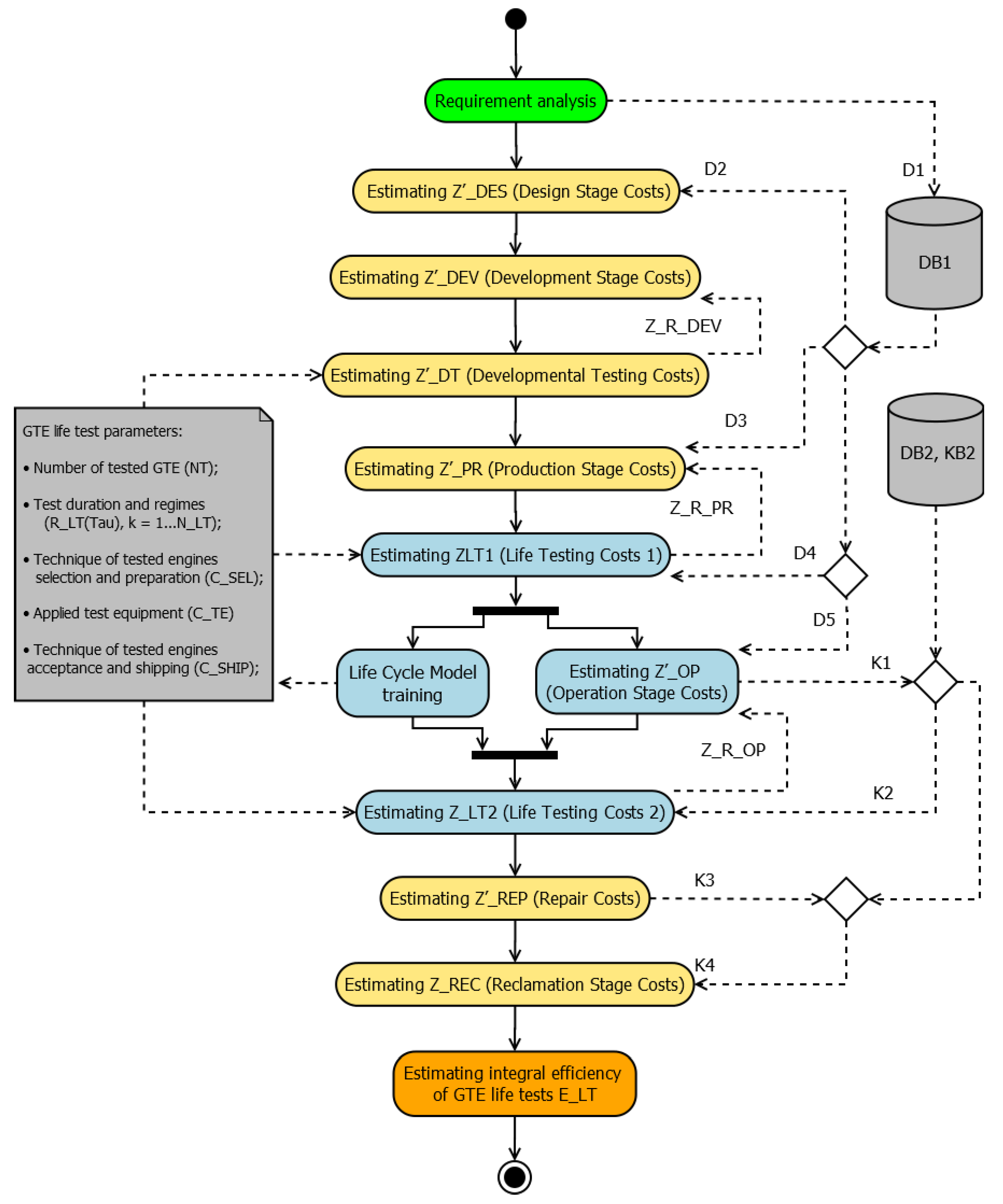
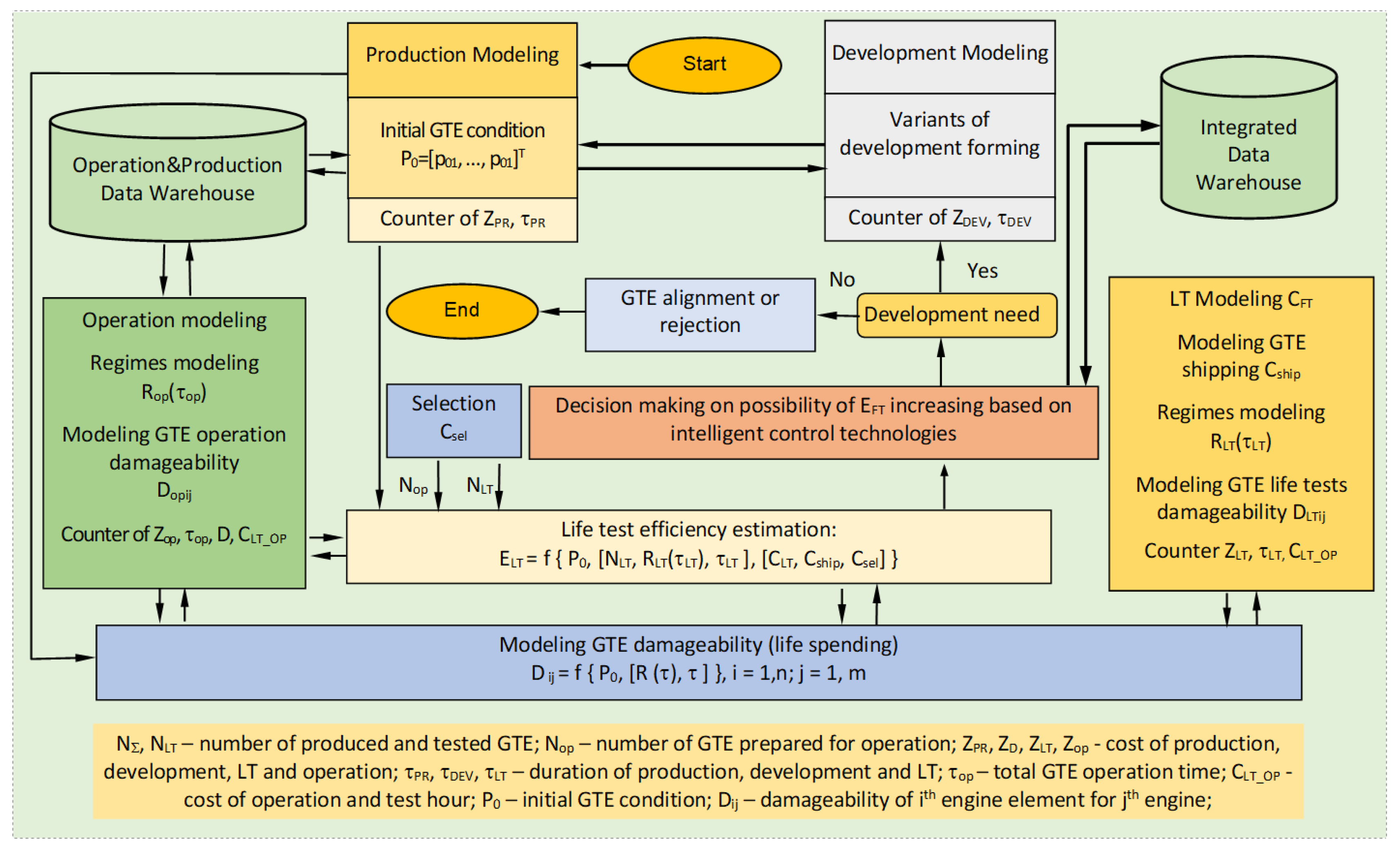
3. Building Statistical Model of GTE Life Cycle

The developed statistical model of the engine life cycle can have different levels of complexity; for example, for a mass-produced engine, the model can be presented in the form “production—periodic life tests—operation”, and for a newly developed product, it can be presented as “design—development tests—production—periodic life tests—operation—disposal”. The flow chart of the process of selecting the parameters of life tests based on the simulation model of the engine life cycle is shown in Figure 3.
The initial data for the model building were statistics collected during numerous existing engines’ life cycle stages (i.e., data on airplanes’ flight schedules, weather information, production quality control, etc.)
The production stage model allows the evaluation of the quality of GTE production, defined by a set of given parameters p01  ( i = 1 , ν ) . As is known, technological operations, assembly procedures, and GTE quality control are the key characteristics that provide quality with a given productivity level and cost. Furthermore, the technological process is characterized by a certain set of initial characteristics P0 = [p01, …, p]T: durability, fatigue, geometric parameters, etc.
Since the components and parts of the gas turbine engine are manufactured with an acceptable error, statistical laws determine the quality indicators of the entire gas turbine engine. Quality parameters are random variables with known distribution laws. This is why the performance indicators during the operation of gas turbine engines also obey static laws. Thus, the higher the accuracy of the manufacturing GTE elements and assemblies, the higher the reliability of the GTE and the lower the probability of damage to its elements, assemblies, and subsystems, i.e., a longer gas turbine engine lifetime in serial operation.
The GTE life test model usually takes account of characteristics such as the number of tested engines NLT, RLTςLT), operation modes, and the time of their loading τLTς (ς = 1, NLT). Different characteristics that define the efficiency of the life test can be also taken into account:
  • Some parameters of GTE batch selection and preparation of chosen GTE for testing CSP = [cSP1, …, cSPυ]Т;
  • Characteristics of acceptance and shipment of engine processes based on testing results CCAS = [cCAS1, …, cCASξ]Т);
  • Performance of special test equipment CE = [cE1, …, cEμ]Т and others.
Because of the modeling at this stage, the resources and durability of the tested GTE sample are estimated. On the basis of the assessment obtained, the engineer makes a decision on the shipment or rejection of the GTE batch, on the selected copy of which the tests were carried out.
The model of the operation stage takes into account the influence of environmental factors and their characteristics, the number of engines in operation NOP, the operating modes ROPkOP), and the time τOPk of their operation (k = 1, NOP). A given operation strategy is also modeled, i.e., terms are taken into account (for a fixed term, conditional work, and combined strategy). For all models of the operation stage, the input parameters are the number of gas turbine engines in operation and the quality of gas turbine engine manufacturing.
The simulation outputs are the characteristics of the integral efficiency of the operation of the engines ELT: the costs and income from the operation process, the probability of GTE performing its functions, etc.
While optimizing the integral efficiency of GTE operation, the following factors are used:
ELT = f(NLT, RLT(τ), CSP, CCAS, CE),
where:
NLT is the number of tested engines;
RLTςLT) are operation modes;
τLTς is time of operation loading (ς = 1, NLT);
CSP are parameters of GTE batch selecting and preparing chosen GTE for testing;
CCAS are characteristics of GTE acceptance and shipment based on life tests results;
CE are performances of the special test equipment.

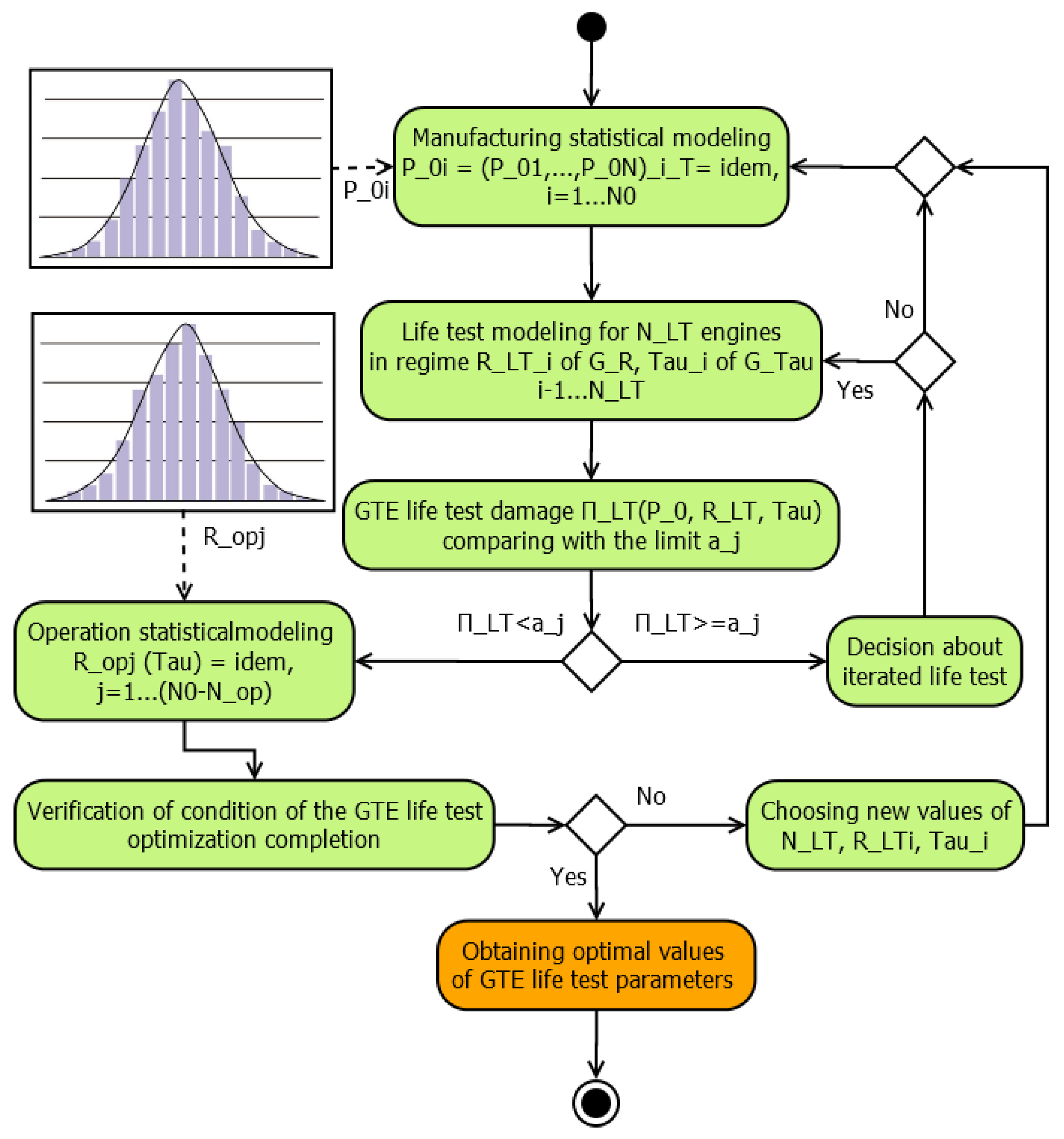
4. GTE Life Test Optimization
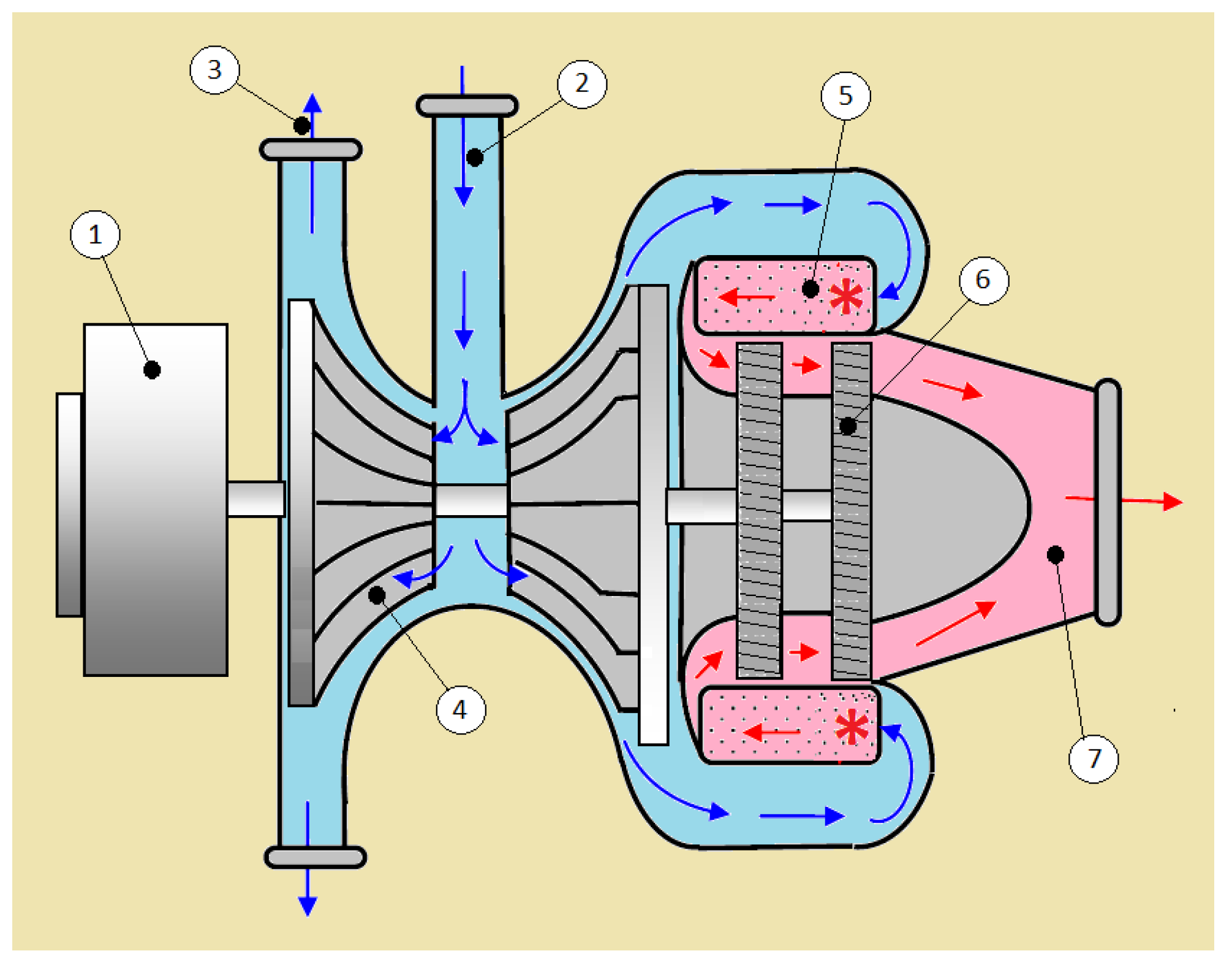
The solution to the problem of determining the maximum efficiency ELT is achieved by choosing the required number of GTEs to be tested NT, their test modes RTT), and the duration of the tests τT:
{ E LT = max f [ N LT , R LT ( τ LT ) , τ LT , C Σ ] ; R LT ( τ LT ) G R , τ LT G τ ,
where:
CΣ is a function including LC characteristics that are constant in the test optimization procedures;
GR and Gτ are the sets of the test modes and their duration.
To find a solution to Equation (2), we need to define the function f(.). For this, it must be taken into account that the main requirement for the accelerated testing of gas turbine engines is to minimize the test time, for which the specified accuracy of matching the damage characteristics of engine elements and damage characteristics during the operation of the gas turbine engine is ensured:
E LT max ( K A = τ op / τ LT ) ;
D LT [ P 0 , R LT ( τ LT ) , τ LT ] = D op [ P 0 , R op ( τ op ) , τ op ] ; P 0 = idem ; R LT ( τ LT ) , R op ( τ op ) G R ,
where:
KA is the test acceleration factor;
DLT[P0, RTT), τT] is GTE damageability in LT depending on the initial condition vector P0, modes RTT), and test duration τT;
Dop[P0, Ropop), τop] is engine damageability in operation depending on the initial condition vector P0, modes Ropop), and operation duration τop;
GR is the set of working modes in which the damageability of the GTE elements and units remains.
Since it is difficult to ensure the fulfillment of Condition (3) in real-life tests, the optimization of the test program is carried out by considering the following:
E L T { max K A ; δ D = | D LT [ P 0 , R LT ( τ LT ) , τ LT ] D op [ P 0 , R op ( τ op ) , τ op ] | ; P 0 = idem ; R T ( τ T ) , R op ( τ op ) G R ,
or by combining КA and δD.
The choice of the test parameters can be made under condition F:
F Σ = max α 1 1 n i = 1 n ( D op . i . ν i [ P 0 , R op ( τ op ) , τ op ] D Ti [ P 0 , R LT ( τ LT ) , τ LT ] D op . i . ν i [ P 0 , R op ( τ op ) , τ op ] ) 2 + α 2 ( τ op τ LT ) 2 ; δ D ¯ = 1 n i = 1 n [ D LTi D op . i . ν i D op . i . ν i ] δ D ¯ ; R LT ( τ LT ) , R op ( τ op ) G R ; τ LT , τ op G τ ; ν i [ 1 N op ] ,
where:
DLTi and Dop.i.νI are the damageability of the i-th part of the GTE in test mode and operation mode;
τLT and τop are the loading time in test mode and operation mode;
Nop is the number of engines in operation;
α1 and α2 are weight factors (α1 + α2 = 1);
δ D ¯ is the maximum acceptable relative average difference of operational and testing damageability of the GTE (Figure 4).
When accounting for the economic factor (the value of operation and test hour) CLT_OP, function FΣ can be presented as a convolution of factors δD, КA, and CLT_OP:
F Σ = max α 1 1 n i = 1 n ( D op . i . ν i [ P 0 , R op ( τ op ) , τ op ] D Ti [ P 0 , R LT ( τ LT ) , τ LT ] D op . i . ν i [ P 0 , R op ( τ op ) , τ op ] ) 2 + α 2 ( τ op τ LT ) 2 + α 2 C LT _ OP 2 ; δ D ¯ = 1 n i = 1 n [ D LTi D op . i . ν i D op . i . ν i ] δ D ¯ ;   R LT ( τ LT ) , R op ( τ op ) G R ; τ LT , τ op G τ ; ν i [ 1 N op ] ,
where:
α1, α2, and α3 are weight factors (α1 + α2 + α3 = 1).
While finding the optimal solution, we need to consider Dop.i.νi in Equation (7) to have a different value (see Figure 4) caused by the operation strategy and GTE production quality As an optimization method, we used the choice of a set of Pareto-optimal solutions, which is a selection of promising alternatives, from which one (best) alternative was then selected [38,39].

5. Case Study

Consider the case study of life test optimization based on life cycle simulation for an auxiliary power unit (APU). An APU is an additional source of power that is not aimed to propel the aircraft. Its functions are to start the propulsion engine as well as provide the power supply to the aircraft. These features cause the particularities of the engine working modes and the life cycle as a whole. A simplified diagram of the APU is shown in Figure 5.
The consideration in this example APU is intended for [40]:
  • Air starting of aircraft propulsion engines at airfields;
  • The supply of compressed air to air-driven devices in flight during emergency use in the case of failure of the main energy sources;
  • The power supply of the aircraft onboard network with AC and DC power on the ground and in flight in case of failure of the main power sources.
The following engine parts were considered life-limiting for this APU: radial thrust bearing; turbine rotor blade; auxiliary fan bearing; drive gear of the reducer; AC generator; and DC generator. The following parameters were used as engine loading factors:
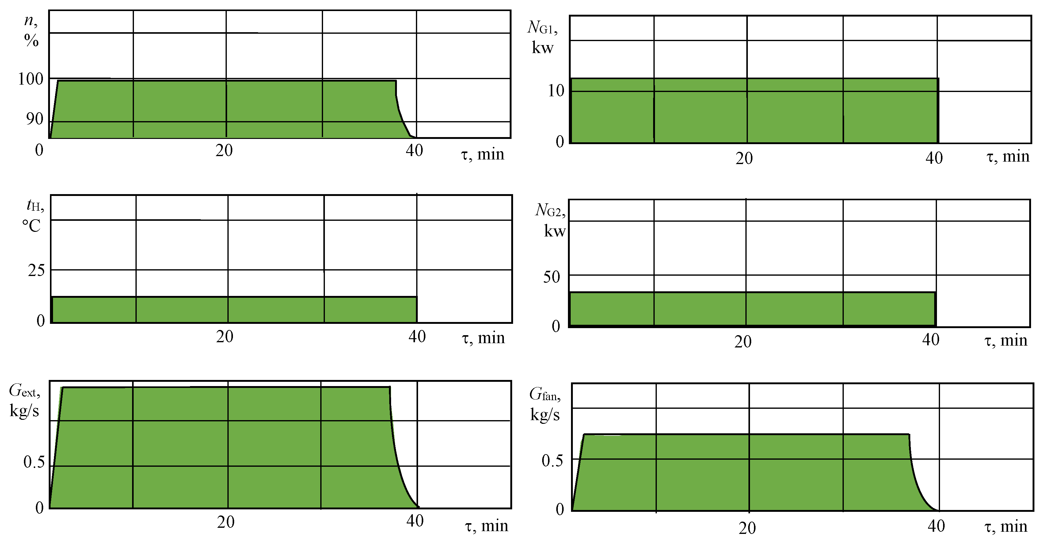
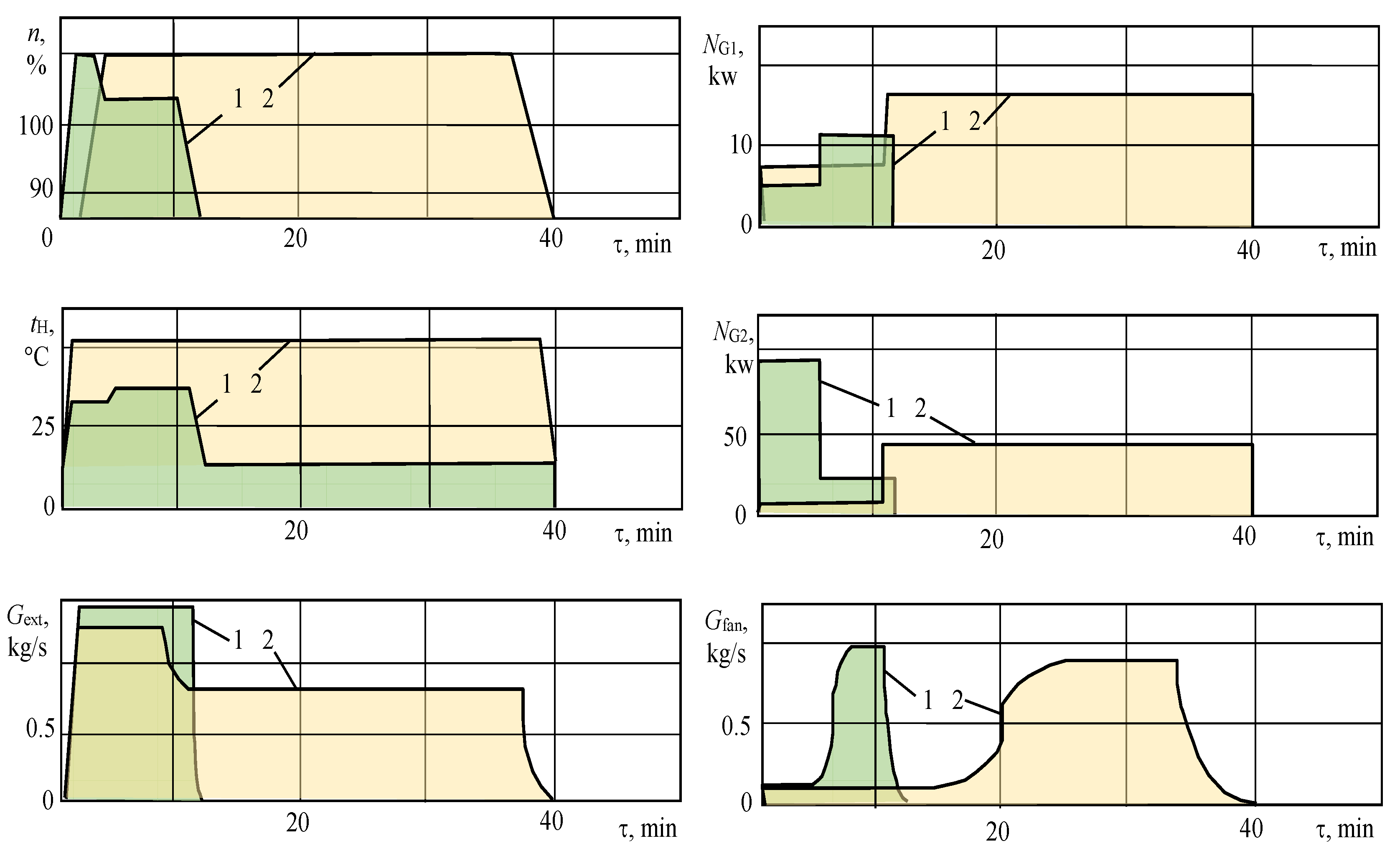
  • Relative rotational speed of the rotor n, %;
  • Engine inlet temperature tн, °C;
  • Air consumption taken from the compressor Gext, kg/s;
  • Fan air consumption Gfan, kg/s;
  • AC and DC generators’ useful power NG1 and NG2, kw.
In this example, the life cycle model assumes the operation of the engine for a fixed life limit. The operation modeling method was applied, in which, within the framework of the simulation model of the testing and operation stages, an array of damage accumulation of the “critical” engine parts was obtained. The performance of simulation-based tests was compared to conventional engine life tests previously developed by the manufacturer using traditional methodologies. Periodic tests are carried out to control the stability of the technological process of manufacturing GTE assembly units and confirm the possibility of continuing their manufacture. Periodic tests should be carried out at least once a year on assembly units from any batch accepted for control and selective testing during a given year. In this example, a periodic test program is provided to verify the service life of 2000 h and 3000 engine starts. In this case, one APU was selected for periodical testing. The serial test program has its own set of characteristics (Table 1) and GTE duty cycle (Figure 6).
The effectiveness of the experimental test program was compared for two opposite variants:
  • The duration of the experimental tests was compared. Herewith, the maximum allowable difference in the damageability of the engine components in serial and experimental tests was set to the same value: (δD*i)exp = (δD*i)ser = 20%;
  • The difference between the accumulation of damage by engine components was compared with the same test time (τLT.exp = τLT.ser).
Two cases were proposed in the framework of the research in order to evaluate the life test efficiency via two different strategies, i.e., achieving maximal accelerating (losing damageability equivalence) and increasing equivalence within the serial life test duration. This approach allowed research on the GTE life cycle simulation model.
The study was carried out taking into account the “critical” elements of the engine, i.e., the elements with the lowest bearing capacity in terms of the main factor of destruction (long-term strength, low-cycle strength, contact strength, and thermal aging) [9,11]. The simulation of life spending (damageability) was carried out by simulating the accumulation of damage by engine elements depending on the quality of their production (initial conditions) and loading conditions in tests or operation [15].
In the case study, a certain set of initial data was implied:
  • Damageability model of the radial thrust bearing:
D B = 0 t 1 τ * [ ( n , T a * , P a * ) , ( e , C B , X ) ] d t ,
where:
n is the relative rotational speed of the rotor, %;
T*a is the engine inlet temperature, K;
P*a is the engine inlet pressure, kg/cm2;
e is the bearing radial clearance as a function of the quality of production, m;
CB is bearing dynamic durability is a function of e and other factors denoted X ¯ ;
  • Damageability model of the turbine’s first stage rotor blade:
D r b = 0 t d t a 1 d t , a 1 = m σ rb 7.02 1 0 - 3 T rb 20 ; m = f ( T rb ,   k ) ∈  G m ;
σ rb = a 0 + a 1 n 2 + a 2 P a * + a 3 n P a * / T a * ; T r b = [ ( b 0 + b 1 n 288 / T a * ) ( T a * / 288 ) ] ,
where:
a0...a3, b0, and b1 are immutable parameters;
m is the durability parameter as a function of blade body temperature Trb and the material parameter k;
n, T*a, and P*a are parameters of engine loading;
  • Damageability models of auxiliary fan bearing, drive gear of the reducer, DC generator, and AC generator:
D i = τ / τ * [ P 0 ,   R i ( τ ) ,   τ ] ;   i = 1.5 ¯ ;   P 0 G R ,
where:
i is an element number, i.e., i = 1 corresponds to the rotor blade;
i = 2 corresponds to the angular contact rotor bearing, etc.
  • The limits of the values of the parameters of the loading mode:
80 n 110 % ;   245 T a * 620   K ;   0.72 P a * 12   kg / cm 2 ;
n = 95 %   ( T a *     340   K ) ;   n = 105 %   ( T a *  >  340   K ) ;
  • Test and operational hour cost:
C LT _ OP = 12.063 ( τ LT _ OP 500 3 ) 2 15.755 ( τ LT _ OP 500 3 ) + 183.53   c . u . ;
  • Possible number of presenting for test engines (NLT∈1…3).
The following test methodology was applied. The engine set was rejected if one of the tested engines NLT failed the test. If one of the engines failed in operation, this engine was repaired, and the remaining engines were operated without additional measures to ensure reliability. Life test optimization was conducted with provision for the objective Function (7).

6. Results and Discussion

The operation of 200 engines for a fixed life was modeled on the basis of collected statistical data. The level of the engine elements’ damageability equivalence in testing and operation is presented in Table 2.
The comparative efficiency of serial and experimental periodic life tests is shown in Table 3. The optimal engine loading cycles in experimental tests are presented in Figure 7.
In the course of the optimization of life tests according to the proposed Pareto-optimal method, the recommended number of GTEs presented for life tests NLT = 1. At the same time, it was possible to increase the level of equivalence of damage in tests and operation by 27 times, reduce the duration of tests by 3.3 times, and reduce the cost of an hour of testing (operation) by 2.4 times.
To simulate operational damageability during the optimization of life tests, an operation simulation method was recommended in which the damageability vector of “critical” engine elements formed in the simulation model corresponded to the maximum operational values. At the same time, a guaranteed check of the engine resource in tests was provided.
It was found that the influence of the deviation from the technical specifications of the dispersion of the manufacturing quality parameters of the “critical” elements of the auxiliary engine on the test efficiency was more significant than the influence of the deviation of the mathematical expectations. Therefore, in order to decrease the cost of operation, it is necessary to reduce the dispersion of the manufacturing quality parameters at the manufacturing stage first.
The threshold value of the mathematical expectations and the dispersion of the parameters of the quality of the manufacture of “critical” engine elements were determined, above which life tests are mandatory (since they should reveal the low quality of the products and prevent them from entering into operation). If the quality parameters do not exceed the threshold value (i.e., with guaranteed product quality), it is recommended to conduct only short-term tests (delivery, control, etc.). Obviously, refusal to conduct periodic tests is possible only with guaranteed quality of product manufacturing, a reliable control system, and high-performance indicators of product reliability. At the same time, as is sometimes practiced, only critical elements or components of the product can be subjected to periodic tests. This will reduce the time and material costs of testing.
It is recommended to use a rejection value of damage in tests equal to the operational values. In this case, the highest test efficiency is ensured in terms of equivalence and duration criteria, as well as the maximum economic effect from the operation of a batch of engines.
It was established that the greatest influence on the level of equivalence was exerted by the control error in testing the air temperature at the engine inlet: with an increase in the relative error by 5.0 times, the level of test equivalence decreased by 2.25 times. The next most important influence was the rotor speed (a decrease of two times). The values of the control errors of these parameters were determined, the excess of which could lead either to unreasonable rejection of a standard engine in tests or the acceptance of substandard engines. In both cases, there were losses associated with errors in setting the values of the engine loading parameters in the tests. Thus, it is recommended first to monitor the accuracy of control of the temperature at the inlet to the engine and the rotor speed. It was also established that from the point of view of the efficiency of the life tests of the considered engine, the accuracy of measuring the loading parameters corresponding to tests in mass production is optimal.

7. Conclusions

Life testing plays a key role in ensuring the failure-free operation of complex technical objects, such as gas turbine engines. Within the framework of the study, a theoretical substantiation of the integrated optimization of life tests of aircraft gas turbine engines based on simulation modeling of the life cycle was carried out. This allowed the choice of the parameters of the life tests, taking into account the ultimate goal of the created engine, namely the technical and economic effect of its operation.
The problem of comprehensive optimization of life tests was solved using both internal indicators (a measure of the equivalence of damageability of the main elements of engine assemblies in testing and operation, the duration of tests, and the number of tested engines) and an external (economic) indicator of the efficiency of life tests. Thus, it was possible to increase the level of validity of the life tests.
An objective function of an additive type was proposed for the complex optimization of life tests according to the function, which is the sum of normalized criteria, taking into account the weight coefficients. At the same time, the area of compromise solutions was formed by multiple optimizations of the function. This gives the developer of the test program the opportunity to choose the final solution from the Pareto set.
The main principles of the formation of a statistic model of the life cycle of a gas turbine engine in relation to solving the problem of optimizing life tests were substantiated: the principle of information sufficiency, the principle of parameterization, the principle of aggregation, and the principle of constant refinement of the model.
It was established that the developed simulation model of the life cycle can be used to optimize the life test parameters in terms of the average damageability of critical engine elements, the duration of tests, and the economic effect of operating a batch of engines. The model provides an increase in the efficiency of tests for the listed indicators and is also suitable for studying the influence of various factors on the effectiveness of the tests.
On the basis of the considered principles, a simulation model of the life cycle of an auxiliary gas turbine engine (“production—testing—operation”) was built. Optimization of the life tests for the auxiliary GTE led to an increase in the level of equivalence of damageability in tests and operation by 27 times, reducing the duration of tests by 3.3 times and reducing the cost of an hour of testing (operation) by 2.4 times.
In future research work, the authors plan to detail the simulation model on the basis of GTE life cycle statistics and continue researching the model parameters as well as apply the proposed methodology to other types of GTEs.

Author Contributions

Conceptualization, S.V.; methodology, S.V. and N.K.; investigation, N.K.; writing—original draft preparation, N.K.; writing—review and editing, S.V.; supervision, S.V. All authors have read and agreed to the published version of the manuscript.

Funding

This research received no external funding.

Conflicts of Interest

The authors declare no conflict of interest.

Nomenclature

ELTIntegral efficiency of the engine life tests
ZDESDesign stage costs
ZDEVDevelopment stage costs
ZDTDevelopment testing costs
ZPRProduction stage costs
ZPT1Life testing costs
ZOPOperation stage costs
ZPT2Optimized life testing costs
ZREPRepair stage costs
ZRECReclamation stage costs
ZR.DEVAdditional development costs related to risks of incorrect life tests
ZR.PRAdditional production costs related to risks of incorrect life tests
ZR.OPAdditional operation costs related to risks of incorrect life tests
P0Vector of initial state parameters related to production (strength, wear resistance, geometry, etc.)
NLTNumber of tested engines
RLTςModes of life test loading, ς = 1, NLT
τLTςDuration of life test loading, ς = 1, NLT
NOPNumber of operating engines
ROPkModes of the operation loading, k = 1, NOP
τOP Loading time during operation, k = 1, NOP
CSPParameters of GTE batch selection and preparation of chosen GTE for testing
CCASCharacteristics of GTE acceptance and shipment based on test results
CEQuality parameters of the test equipment used
DLTEngine damageability during life tests
DOPEngine damageability during operation
КALife test acceleration factor
Abbreviations
GTEGas turbine engine
LCLife cycle
LTLife test
APUAuxiliary power unit (R4)

References

  1. Klyatis, L.M. Trends in Development of Accelerated Testing for Automotive and Aerospace Engineering; Elsevier: Amsterdam, The Netherlands, 2020; p. 39. ISBN 978-0-12-818841-5. [Google Scholar] [CrossRef]
  2. Yang, G. Life Cycle Reliability Engineering, 1st ed.; John Wiley & Sons: New York, NY, USA, 2007; p. 544. [Google Scholar] [CrossRef]
  3. Soares, C. Gas Turbines: A Handbook of Air, Land and Sea Applications; Elsevier: Amsterdam, The Netherlands, 2015. [Google Scholar]
  4. MacIsaac, B.; Langton, R. Gas Turbine Propulsion Systems; John Wiley & Sons: New York, NY, USA, 2011; p. 328. [Google Scholar]
  5. Yang, G.; Zaghati, Z. Accelerated life tests at higher usage rates: A case study. In Proceedings of the Reliability and Maintainability Symposium, Newport Beach, CA, USA, 23–26 January 2006; pp. 313–317. [Google Scholar] [CrossRef]
  6. Mislick, G.K.; Nussbaum, D.A. Cost Estimation: Methods and Tools (Wiley Series in Operations Research and Management Science); John Wiley & Sons: New York, NY, USA, 2015; p. 340. ISBN 978-1-118-53613-1. [Google Scholar]
  7. Mattingly Jack, D. Elements of Propulsion: Gas Turbines and Rockets; AIAA Inc.: Reston, VA, USA, 2006; p. 928. [Google Scholar]
  8. Farokhi, S. Aircraft Propulsion; John Wiley & Sons: New York, NY, USA, 2014; p. 1048. [Google Scholar]
  9. Gishvarov, A.; Ageev, G.; Davydov, M. Justification of program for accelerated periodic tests of aircraft turbogenerator—alternating current source. In Proceedings of the 2019 International Conference on Electrotechnical Complexes and Systems (ICOECS), Ufa, Russia, 21–25 October 2019; pp. 1–4. [Google Scholar] [CrossRef]
  10. Jaw, L.C.; Mattingly, J.D. Aircraft Engine Control Design, System Analysis, and Health Monitoring; AIAA Inc.: Reston, VA, USA, 2009. [Google Scholar]
  11. Guichvarov, A.; Kondratieva, N. Technical and economic assessment of aircraft engines fatigue testing on base of simulation modeling. In Proceedings of the 37th AIAA/ASME/SAE/ASEE Joint Propulsion Conference and Exhibit, Salt Lake City, UT, USA, 8–11 July 2001; AIAA-2001-3817. [Google Scholar]
  12. Gupta, B.C. Statistical Quality Control: Using MINITAB, R, JMP and Python; Wiley & Sons: New York, NY, USA, 2021; p. 400. ISBN 978-1-119-67171-8. [Google Scholar]
  13. Montgomery, D.C. Introduction to Statistical Quality Control, 8th ed.; Wiley & Sons: New York, NY, USA, 2019; p. 768. ISBN 978-1-119-39930-8. [Google Scholar]
  14. Kondratyeva, N.; Valeev, S. Fatigue Test Optimization for the Aircraft Engine Based on the Life Cycle Information Support and Modeling. In Proceedings of the 6th International Conference on Industrial Engineering (ICIE 2020), Sochi, Russia, 18–22 May 2020; Radionov, A.A., Gasiyarov, V.R., Eds.; Lecture Notes in Mechanical Engineering. Springer: Cham, Switzerland, 2021; pp. 410–418. [Google Scholar] [CrossRef]
  15. Gurevich, O.S. Aviation GTE Automatic Control Systems: Encyclopedic Reference; Gurevich, O.S., Ed.; Torus Press: Moscow, Russia, 2011. [Google Scholar]
  16. Yang, G.; Zaghati, Z. Two-dimensional reliability modeling from warranty data. In Proceedings of Reliability and Maintainability Symposium, Seattle, WA, USA, 28–31 January 2002; pp. 272–278. [Google Scholar] [CrossRef]
  17. Yang, G.; Zaghati, Z. Reliability and robustness assessment of diagnostic systems from warranty data. In Proceedings of the Reliability and Maintainability Symposium, Los Angeles, CA, USA, 26–29 January 2004; pp. 146–150. [Google Scholar] [CrossRef]
  18. Yang, G.; Zaghati, Z. Robust reliability design of diagnostic systems. In Proceedings of the Reliability and Maintainability Symposium, Tampa, FL, USA, 27–30 January 2003; pp. 35–39. [Google Scholar] [CrossRef]
  19. Jianguo, S.; Vasilyev, V.; Ilyasov, B. Advanced Multivariable Control Systems of Aeroengines; Sun, J., Vasilyev, V., Ilyasov, B., Eds.; BUAA Press: Beijing, China, 2005. [Google Scholar]
  20. Vasilyev, V.; Valeyev, S.; Sun, J. Identification of Complex Technical Objects on the Basis of Neural Network Models and Entropy Approach. In Proceedings of the 9th World Multi-Conference on Systemics, Cybernetics and Informatics, Orlando, FL, USA, 10–13 July 2005; Volume 9, pp. 89–93. [Google Scholar]
  21. Ilyasov, B.; Vasilyev, V.; Valeev, S. Design of Multi-Level Intelligent Control Systems for Complex Technical Objects on the Basis of Theoretical-Information Approach. Acta Polytech. Hung. 2020, 17, 137–150. [Google Scholar] [CrossRef]
  22. Kulikov, G.G.; Thompson, H.A. Dynamic Modelling of Gas Turbines: Identification, Simulation, Condition Monitoring and Optimal Control, Advances in Industrial Control; Springer: London, UK, 2014. [Google Scholar]
  23. Kulikov, G.G.; Arkov, V.Y.; Abdulnagimov, A.I. Markov modelling for energy efficient control of gas turbine power plant. In IFAC Proceedings Volumes; Elsevier: Amsterdam, The Netherlands, 2010; Volume 43, pp. 63–67. [Google Scholar]
  24. Zagitova, A.; Kondratyeva, N.; Valeev, S. Information Support of Gas-Turbine Engine Life Cycle Based on Agent-Oriented Technology. In the Proceedings of the 5th International Conference on Industrial Engineering (ICIE), Sochi, Russia, 25–29 March 2019; pp. 469–476. [Google Scholar] [CrossRef]
  25. Inozemtsev, A.; Petrochenkov, A.; Kazantsev, V.; Shmidt, I.; Sazhenkov, A.; Dadenkov, D.; Gribkov, I.; Ivanov, P. The Fuzzy Logic in the Problems of Test Control of a Bypass Turbojet Engine Gas Generator. Mathematics 2022, 10, 484. [Google Scholar] [CrossRef]
  26. Arkhipov, A.; Ravikovich, Y.; Kholobtsev, D.; Shakhov, A. Calculation and Experimental Study of Low-Cycle Fatigue of Gas Turbine Engines Booster Drum. Inventions 2022, 7, 49. [Google Scholar] [CrossRef]
  27. Cruz-Manzo, S.; Panov, V.; Zhang, Y. Gas Path Fault and Degradation Modelling in Twin-Shaft Gas Turbines. Machines 2018, 6, 43. [Google Scholar] [CrossRef]
  28. Zaccaria, V.; Fentaye, A.D.; Kyprianidis, K. Assessment of Dynamic Bayesian Models for Gas Turbine Diagnostics, Part 2: Discrimination of Gradual Degradation and Rapid Faults. Machines 2021, 9, 308. [Google Scholar] [CrossRef]
  29. Fentaye, A.D.; Zaccaria, V.; Kyprianidis, K. Aircraft Engine Performance Monitoring and Diagnostics Based on Deep Convolutional Neural Networks. Machines 2021, 9, 337. [Google Scholar] [CrossRef]
  30. Sause, M.G.R.; Jasiūnienė, E. Structural Health Monitoring Damage Detection Systems for Aerospace; Springer: Cham, Switzerland, 2021; p. 284. ISBN 978-3-030-72194-7. [Google Scholar] [CrossRef]
  31. Valeev, S.; Kondratyeva, N. Design of Nonlinear Control of Gas Turbine Engine Based on Constant Eigenvectors. Machines 2021, 9, 49. [Google Scholar] [CrossRef]
  32. Zhu, S.-P.; Yue, P.; Yu, Z.-Y.; Wang, Q. A Combined High and Low Cycle Fatigue Model for Life Prediction of Turbine Blades. Materials 2017, 10, 698. [Google Scholar] [CrossRef] [PubMed]
  33. Peitz, S.; Dellnitz, M.A. Survey of Recent Trends in Multiobjective Optimal Control—Surrogate Models, Feedback Control and Objective Reduction. Math. Comput. Appl. 2018, 23, 30. [Google Scholar] [CrossRef]
  34. Ji, S.; Han, X.; Hou, Y.; Song, Y.; Du, Q. Remaining Useful Life Prediction of Airplane Engine Based on PCA–BLSTM. Sensors 2020, 20, 4537. [Google Scholar] [CrossRef] [PubMed]
  35. Klyatis, L.M.; Anderson, E.L. Reliability prediction and Testing Textbook; John Wiley & Sons: New York, NY, USA, 2018; p. 272. ISBN 978-1-119-41193-2. [Google Scholar]
  36. GT Auto Tuner: First System Worldwide to Leverage Physics and Reinforcement Learning to Optimize Gas Turbine Operation. Available online: https://www.siemensenergy.com/global/en/offerings/services/digital-services/gt-autotuner.html (accessed on 16 August 2022).
  37. Valeev, S.; Kondratyeva, N. Process Safety and Big Data; Elsevier: Amsterdam, The Netherlands, 2021; p. 302. [Google Scholar] [CrossRef]
  38. Gatter, T.; Giegerich, R.; Saule, C. Integrating Pareto Optimization into Dynamic Programming. Algorithms 2016, 9, 12. [Google Scholar] [CrossRef]
  39. Zhang, C.; Wei, J.; Jing, H.; Fei, C.; Tang, W. Reliability-Based Low Fatigue Life Analysis of Turbine Blisk with Generalized Regression Extreme Neural Network Method. Materials 2019, 12, 1545. [Google Scholar] [CrossRef] [PubMed]
  40. Li, J.; Wang, Y.; Chen, J.; Zhang, X. Study on energy management strategy and dynamic modeling for auxiliary power units in range-extended electric vehicles. Appl. Energy 2017, 194, 363–375. [Google Scholar] [CrossRef]
Figure 1. GTE Life cycle and the data acquisition system.
Energies 15 06874 g001
Figure 2. The conceptual diagram of the GTE LC model for optimizing parameters of life test.
Energies 15 06874 g002
Figure 3. The flow chart of the process of the life test parameters assessment in the framework of the engine life cycle.
Energies 15 06874 g003
Figure 4. Generalized scheme of choosing life test parameters for the GTE on the basis of the life cycle model.
Energies 15 06874 g004
Figure 5. A principal scheme of an auxiliary power unit: 1 is an electrical generator, 2 is inlet air, 3 is compressed air, 4 is a centrifugal compressor, 5 is a combustor, 6 is a turbine, and 7 is exhaust.
Energies 15 06874 g005
Figure 6. APU duty cycles in serial periodic life tests (NLT = 1).
Energies 15 06874 g006
Figure 7. Optimal engine loading cycles in experimental periodic life tests (N*LT = 1): curve 1 is the loading cycle at (δDi)exp = (δDi)ser; curve 2 is the loading cycle at τtest.exp = τtest.ser.
Energies 15 06874 g007
Table 1. Parameters of the periodic serial life testing.
Parameter (Description)Given Value
Cycles of loading3000 cycles
Stage of testing duration50 h
Cycle time40 min
Number of testing stages40 stages
The number of cycles per stage30 cycles
Total testing time2000 h
Table 2. Level of the engine elements’ damageability equivalence in testing and operation.
Engine PartLevel of the Engine Elements Damageability
Equivalence δDi, %
Serial Periodical TestExperimental Test (δDi)LT = (δDi)OPExperimental Test (τLT.exp = τLT.ser)
Turbine rotor blade4795100
Radial thrust bearing4513100
Auxiliary fan bearing171142100
Drive gear of the reducer291846
DC generator11011048
AC generator10511250
Table 3. Comparative efficiency of serial and experimental periodic life tests.
Periodic TestsδDi, %τLT, HoursCLT_OP, c.u.
Serial29.82000380.1
Experimental (δDi)LT = (δDi)OP29.5608159.7
Experimental (τLT.exp = τLT.ser)1.12000377.9
Publisher’s Note: MDPI stays neutral with regard to jurisdictional claims in published maps and institutional affiliations.

