1. Introduction
The first rock mining with the use of a shearer dates back to the second half of the 19th century, when the roadheader was used in an attempt to drill a tunnel under the English Channel from England to France in 1870. It was a Channel drilling rig, which drilled 2.4 km of the tunnel in hard limestone rocks. The machine worked on a track chassis and was moved hydraulically [
1].
The first longwall shearers were equipped with a cutting head in the form of a cutter gib and one or two poles with crushing discs. They mined the face by cutting a strip over the entire surface of the longwall by means of cutter gibs. In 1932, Major Coulson constructed a JaR longwall shearer based on the earlier design of the cutter. The shearer had a horizontal chain cutter gib and a vertical pole cutter gib. The machine, powered by a 31 kW electric motor, cut a 1.6 m wide strip of coal [
1].
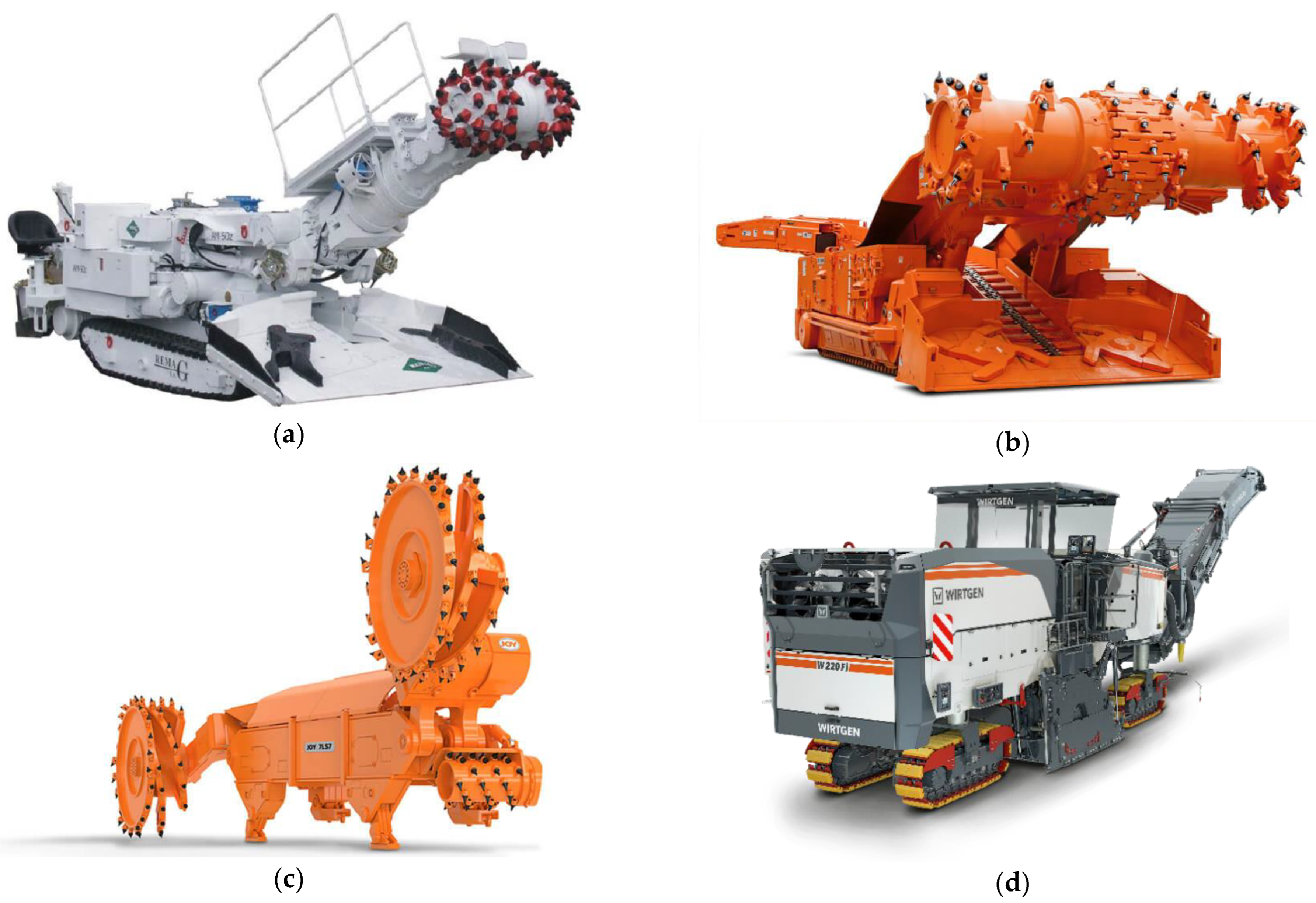
Currently, both selective cutting roadheaders (
Figure 1a) [
2,
3] or continuous miners (
Figure 1b) [
4,
5] and longwall shearers (
Figure 1c) [
6,
7] mine the face with cutting heads. They are used not only in mining machines, but also in construction and road machinery, such as road milling machines (
Figure 1d) [
8,
9] or excavators [
10,
11,
12,
13].
Modern mining machines have cutting heads, which are usually equipped with conical picks [
15,
16,
17,
18,
19]. These picks are designed for mining hard or even very hard rocks [
20,
21,
22,
23,
24]. However, they require maintenance of appropriate parameters of their work, hence it is extremely important that the cutting head itself is properly designed [
25].
The analysis of cutting heads is carried out due to the possibility of making changes in the pick arrangement, allowing the power consumption, force in the direction of shearer advance and their variations to be reduced.
A solution to a given problem is sought by assessing the parameters of the machines and the excavation, as well as by selecting the cutting heads. Therefore, it is required to analyse:
- ‒
the technical equipment used in the excavation,
- ‒
the parameters of the cutting machine (shearer),
- ‒
the cutting parameters of the cutting heads.
The above-mentioned analyses allow evaluation of the parameters of the machines and equipment used, while taking into account the mining and geological conditions of the excavation. Then it is possible to propose changes to the cutting heads (pick arrangement) or to make new ones. This can be achieved by taking into account the requirements of the mining process (cutting, loading) and the properties of the rock (susceptibility to crushing, resistance to displacement) [
26,
27]. However, this requires appropriate calculations and analyses, which have been presented in this article.
2. Resistance to Mining with Cutting Picks
The general process of cutting involves applying a sufficiently large force
P, that will be able to overcome the resistance forces generated by the material being cut, which are dependent on the depth of cut, design parameters and cutting tool angles. Force
P can be broken down into three perpendicular components:
Ps—cutting force, which works in the direction of the groove and has the greatest impact on the cutting process,
Pd—pressure force, which is perpendicular to the bottom of the groove and overcomes the friction force and
Pb—lateral force, which is perpendicular to the cutting force and pressure force (
Figure 2). It was assumed that the forces
Pd and
Pb were determined as products of the force
Ps and the proportionality coefficients
kd (4) and
kb (5) [
26,
27].
The tests of resistance to mining with cutting picks have revealed that the cutting force
Ps is the greatest force and it is proportional to the depth of cut. As a result of these assumptions, the following forces were obtained:
Ps,
Pd and
Pb [
26,
27].
where:
ξ—pick deflection [o],
Bn(i)—pick width [cm],
A—cutting coefficient [N/cm],
gs(i, j)—cutting depth [cm],
β—side crushing angle [o],
T(i)—distance from the nearest pitch the picks of which are in the face [cm],
i—pick number,
j—number of the consecutive rotation by angle
φ.
where:
kd—Pd force proportionality index (kd = 0.4 ÷ 0.8),
kb—Pb force proportionality index (kb = 0.2 ÷ 0.4).
Knowing the values of the forces that act on a single pick (
Figure 3) enables reduction of these forces at the beginning of the shaft on which the cutting head is mounted [
26,
27].
where:
Apart from the forces
Px,
Py and
Pz, the cutting head body is influenced by the moments of forces, which can be determined from the following relationships [
26,
27].
where:
The above dependences allow determination of the load of the cutting head as a function of its structural and kinematic parameters and the pick arrangement, as well as the cutting picks themselves. Of course, such calculations enabling the assessment of the cutting head in terms of its minimum load and variability of cutting resistance forces and moments require the use of appropriate software.
3. Software
Designing the shearer cutting head is a complex process, which requires multiple calculations of the above dependencies, as well as adjustments of the input data assumptions needed for calculations and the change of cutting tools positioning on the cutting head. Manual recalculation of the above dependences is time-consuming and arduous. For this reason, a computer program was developed to automate the computational process [
29]. The program algorithm is shown in
Figure 4.
The input data for the program include: diameter of the cutting head drum, speed of shearer advance, rotational speed of the cutting head, side crushing angle, workability index, cutting height, pressure force and lateral force proportionality indexes, dimensions of the holders, pick dimensions and position of picks on the cutting head.
After the input data have been entered into the program (
Figure 5) and calculations have been made, the program graphically presents the layout of the cutting tools on the diagram of pick arrangement on the cutting head (
Figure 6) and the arrangement of cuts generated by the designed cutting head (
Figure 7). In the event that any irregularities related to the positioning of the pick or the cut are visible in any of the drawings, it is possible to correct the input data and/or the cutting tools’ layout. The third basis for corrections are tabular results of the calculations (average values and their variations), the waveforms of forces and moments acting on a single cutting tool, as well as the resultant forces and moments of all the tools (
Figure 8). It is possible to analyse forces, moments and the power and depth of cut for each pick separately, as well as for parts of picks and resultants of all the picks. Determination of the minimum cutting resistance for the analysed cutting heads is of key importance. The process of corrections is repeated until satisfactory results are obtained.
4. Example of Application
The data required for this analysis are summarised in
Table 1 and
Table 2.
Table 1 contains the mining and geological data of the longwall, whereas
Table 2 presents the technical data of its equipment (parameters of the longwall shearer system).
Table 1 shows that the longwall has a length of 240 m and a height of 3.2 m. The longitudinal slope of the longwall is 3.6° and the transverse slope 3.1°. This seam contains energy coal with the symbol 31.2. Coal mining is carried out in a longwall caving system, with two-way operation of a longwall shearer equipped with cutting heads without cover loaders. The technical equipment of the longwall (
Table 2) consists of a mining machine (longwall shearer), a longwall powered support and an armoured face conveyor. The excavated material is collected from the face conveyor using a beam stage loader.
The longwall shearer is equipped with two arm heads with a 300 kW motor each, forcing the rotation of the cutting heads. The mining machine movement along the longwall is carried out by means of a chainless haulage drive equipped with two motors; each of them has a power of 60 kW and allows obtaining of the maximum working speed of advance vpmax ≤ 10.0 m/min.
The longwall shearer is equipped with heads with a diameter of 2030 mm and a web of 800 mm which work at 37 revolutions per minute.
The data summarized in
Table 1 and
Table 2 enable evaluation of the cooperation of machines and devices of the longwall system in terms of obtaining the assumed daily production, proper implementation of the mining process and determination of the permissible speed of the longwall shearer advance (cutting, loading) so as to avoid secondary crushing of the excavated material, and, in consequence, a reduction in the speed of the cutting machine and increased dustiness. The data also allows development of assumptions and guidelines for the selection of the cutting parameters of worm-type cutting heads for the longwall shearer.
4.1. Assessment of the Cooperation of Longwall System Machines
The machines and equipment included in the longwall complex should have appropriate technical and operational parameters. Due to the fact that the only operational parameter that can be changed and regulated at any time is the longwall shearer advance speed, the value of this speed must be adjusted to the capabilities of other machines.
The applied support with a 1.5 m pitch should move behind the shearer within a time of up to 9 s (roof support) to prevent its fall, for the working advance speed vpmax = 10 m/min, whereas for the manoeuvring advance speed vpm = 20 m/min, the support shift time should not exceed 4.5 s.
The face conveyor’s ability to take over the excavated material is an important factor that enables achievement of the assumed efficiency of the mining machine and grain size distribution of the excavated material. For a longwall conveyor with a capacity of Qt = 1500 Mg/h, chain speed vt = 1.44 m/s, with two-way mining, the permissible advance speed cannot exceed vpz = 4.50 m/min for the compatible movement of the roadheader and the chain, and for the opposite movement vpp = 5.02 m/min, when the longwall height is H = 3.2 m.
The shearer’s operational parameters vpmax = 10 m/min and n = 37 rpm allow determination of the maximum cutting depth, gsmax = 270 mm. This depth should be smaller than the sum of the heights of picks in the cutting line so as to prevent cutting with holders and their covers. Based on the above information, the following comments, recommendations and conclusions can be formulated:
- ‒
the permissible advance speed of the shearer in two-way mining, in a longwall with a height H = 3.2 m, resulting from the conveyor’s ability to take over the excavated material, cannot exceed the value of vpz = 4.5 m/min in the case of compatible direction (shearer, conveyor) and vpp = 5.02 m/min in the case of opposite direction,
- ‒
maximum cutting depth per one rotation of the head for n = 37 rpm and vpmax = 10 m/min is gsmax = 270 mm,
- ‒
the support shift time should not exceed 9 s (tob = 1.5 m, vpmax = 10 m/min),
- ‒
if the mining machine exceeds the advance speed resulting from the conveyor’s capacity to take over the excavated material, the excavated material circulation in the cutting heads, its degradation and dustiness increase,
- ‒
in order to reduce the excavated material degradation, it is recommended that the advance speeds resulting from the conveyor’s ability to take over the excavated material be used,
- ‒
the beam stage loader should have a capacity greater than that of the face conveyor or equal to it; also, the chain speed should be greater than or equal to that of the face conveyor, which is fulfilled in this case.
4.2. Evaluation of the Cutting Parameters of the Cutting Heads
The above comments and conclusions, as well as the requirements set by the user, provide a basis for assessing the design and kinematic parameters of the cutting heads of the longwall shearer subjected to analysis. It should be noted, however, that the assessment of the selection of cutting tools in this case involves determining their appropriate design parameters so that they can perform the cutting and loading process in a correct way [
26,
27].
Due to the technical parameters of the longwall, in particular its height H ≤ 3.2 m, as well as the parameters of the mining machine and the powered support, the use of worm-type cutting heads with a diameter of more than 2000 mm and a web of 800 mm is preferred. Cutting heads with such diameters have four blades on the cutting-loading part, inclined at an angle of 19 ÷ 23° (Polish hard coals). However, the analysed heads with a diameter of 2030 mm and a web of 800 mm have only three blades, inclined at an angle of 15°. Hence, there are limitations related to the total number of picks on the head in the cutting line (maximum three picks), the pitch between the cutting lines, the types of cuts (compatible, alternate) and the shearer advance speed.
In order to make sure that the cutting and loading processes are carried out in a correct way, the ⌀2030 × 800 heads with three blades on the cutting-loading part allow the maximum speed of the shearer
vpmax ≤ 10 m/min in the event there are three picks in the cutting line (cutting,
gsmaxi =
gsmax/3 picks = 270/3 = 90 mm). The internal volume of the cutting head (loading) limits this speed to 4 m/min to prevent the excavated material degradation (comminution) [
26,
27]. Naturally, in practice this speed can be higher (
vpmax ≤ 10 m/min), but this results in increased cutting resistance and dustiness.
Additionally, the analysed cutting heads were characterized by the following parameters (cutting, loading):
- ‒
head revolutions n = 37 rpm,
- ‒
body diameter Db = 1700 mm,
- ‒
inclination of blades αp = 15°,
- ‒
number of blades i = 3,
- ‒
hub diameter dp = 900 mm,
- ‒
blade thickness bp ≤ 60 mm,
- ‒
disc thickness bt ≤ 90 mm,
- ‒
body width B ≥ 740 mm.
Each head is equipped with 38 pick holders with sleeves (14 on the cut-off disc, 24 on the blades), without spraying nozzles (
Figure 9), welded into sockets located in the body (
Figure 10). The holders, on the other hand, have been equipped with picks whose working part length is
Ln = 102 mm (
Figure 11). The height of a pick with a holder is
Hn = 167 mm. By subtracting the height of the sheet metal covering the holders (90 mm) from the height
Hn = 167 mm, the height that can be used in the cutting process is obtained. Hence, the maximum advance speed reached
vpmax ≤ 8.55 m/min (cutting,
gsmaxi = 167 − 90,
n = 37 rpm).
The above information allowed formulation of the following comments, recommendations and conclusions:
- ‒
the achievable speed of the shearer advance vpmax = 20.0 m/min is a manoeuvring speed and cannot be used for mining,
- ‒
due to cutting, the maximum advance speed for these cutting heads (three picks in the cutting line, holder covering) cannot be higher than vpmax ≤ 8.55 m/min,
- ‒
due to the loading process, the maximum advance speed for these heads is vpmax ≤ 4 m/min,
- ‒
due to the face conveyor’s ability to take over the excavated material, the maximum advance speed for H = 3.2 m, vpz ≤ 4.5 m/min, vpp = 5.02 m/min,
- ‒
the time of support (control and power supply system) shift should be adapted to the remaining machines, in this case—to the longwall shearer,
- ‒
it is recommended that the advance speed applied during cutting should not exceed 4.0 m/min,
- ‒
it is proposed to equip the renovated cutting heads with picks and holders characterized by the following parameters (
Figure 3):
conical pick: Ln ≥ 90 mm, 2β = 90°,
holder: Hu = 90 mm, bu1 = 58 mm, b = 20 mm, δu = 45°.
4.3. Proposal of New Pick Arrangements Based on Calculations
For the ⌀2030 × 800 heads (arrangement 1) subjected to analysis, four alternative locations of the holders with picks on the lateral surface of the head were proposed, i.e., the so-called pick arrangements (arrangements 1a ÷ 1d). The proprietary software was used to make calculations for four new variants and compared to the previously analysed solution. An appropriate cutting head for this height of the longwall, i.e., the one with a diameter of 2300 mm and a web of 800 mm (arrangement 2), was also proposed. The calculations in question were also carried out for this cutting head.
The 1a arrangement was characterized by a variable pitch between the cutting lines, where 15 holders were placed on the disc and 21 on the blades, for a total of 36 holders, while the 1b ÷ 1d arrangements differed in the positioning of the holders and the sequence of entering the cut. In the case of the new four-inlet cutting head (arrangement 2), the same holders and picks were used; however, the diameter of the holders’ positioning reached 2000 mm.
The analysis of the pick arrangements in question was conducted with respect to cutting resistance values (power
N, cutting head impact force in the direction of shearer’s advance
Pz) and their variations. The only variables were the pick arrangement parameters. The waveforms of the power value
N for one rotation of the head and the impact force of the head in the direction of shearer’s advance
Pz, at the mining machine advance speed
vp = 4 m/min, have been shown in
Figure 12,
Figure 13,
Figure 14,
Figure 15,
Figure 16 and
Figure 17, where the dashed line shows average value. The computer simulation results are presented in
Table 3.
For each pick arrangement, average values of the total depth of cut gs, the force of the cutting head impact in the direction of shearer’s advance Pz power consumption N, as well as the ranges of their variations for one rotation of the cutting head and advance vp = 4 m/min, have been determined.
It turned out that the proposed four alternative pick arrangements have similar mean values of force Pz and power N, but different ranges of variations of these values. The 1c and 1a pick arrangements are characterized by the smallest ranges of variation of average force Pz and power N.
Given the smallest number of changes to the cutting head body, arrangement 1a should be applied first. It is worth noting that the new pick arrangements have a larger number of picks (39), which should translate into greater reliability while maintaining almost identical cutting resistance. In the future, it is proposed to use a cutting head with pick arrangement 2, characterized by four blades and an alternate arrangement of cuts and a larger diameter, in these mining-geological and technical conditions of the longwall working.
5. Conclusions
The cutting process with the use of a worm-type cutting head is associated with the simultaneous cutting and loading processes. The cutting head parameters that affect the quality of the cutting process can be divided into the following:
- ‒
design parameters and the resulting pick arrangement, as well as the type of cutting tools,
- ‒
shearer operational parameters influencing the cutting process.
Both groups of factors affect the shearer load and the cutting machine durability, as well as the size grade of excavated material and dustiness [
26,
27,
28]. The cutting head parameters that have an impact on the loading process quality can be divided into:
- ‒
cutting head design parameters and the resulting shape of the loading elements,
- ‒
shearer operational parameters influencing the process of loading with the cutting head.
Additional factors influencing the work of the cutting heads and the longwall shearer are the parameters of the remaining components of the longwall complex. The capacity and the speed of chain of the face conveyor should allow it to take over the excavated material from the shearer at different speeds of the mining machine, whereas the support shift time should prevent a roof fall.
The above remarks and recommendations should be taken into account when formulating assumptions for the selection of the parameters of worm-type cutting heads, as well as their pick arrangements (the type of cutting tools and their arrangement on the cut-off disc and the cutting-loading part).
The presented software supporting the selection of the design parameters of the cutting head and the pick arrangement automates the calculation process, shortening the time of design. The presented software potentially allows not only selection of the optimal construction and kinematic parameters of the cutting head to minimize the energy expenditure on the cutting process, but also takes into account the operating parameters of the cutting head to minimize cutting machine vibrations as well as dust and noise. Therefore, it is recommended to use the software to design and select milling heads. The only limitation, in this case, is the reliability of the data related to the parameters of the mined mineral, which is obtained through empirical tests (workability index, side crushing angle).
It is possible to print a complete design report with tables of calculation results and charts, as well as the pick arrangement and the diagram of cuts. The results of calculations can be exported to a spreadsheet, where additional force and moment graphs can be prepared. The data from the spreadsheet can also be sent to the Matlab package, where the diagrams for the needs of this article were prepared.
Author Contributions
Conceptualization, K.K.; Data curation, T.W. and R.K.; Formal analysis, K.K., K.M. and T.W.; Methodology, K.K.; Project administration, K.M.; Resources, T.W. and R.K.; Software, R.K.; Supervision, K.K.; Validation, R.K.; Visualization, T.W. and R.K.; Writing—original draft, K.K. and K.M.; Writing—review & editing, K.M. All authors have read and agreed to the published version of the manuscript.
Funding
Works financed by the AGH University of Science and Technology.
Data Availability Statement
Data presented in the article are original and not inappropriately selected, manipulated, enhanced, or fabricated.
Conflicts of Interest
Authors declare no conflict of interest.
References
- Gierlotka, S. Rozwój techniki urabiania w górnictwie węglowym—Urabianie kombajnami. In Dzieje Górnictwa—Element Europejskiego Dziedzictwa Kultury; Zagożdżona, P.P., Madziarza, M., Eds.; Wrocław University of Science and Technology Press: Wrocław, Poland, 2010; Volume 3, pp. 102–110. (In Polish) [Google Scholar]
- Cheluszka, P. Optimization of the Cutting Process Parameters to Ensure High Efficiency of Drilling Tunnels and Use the Technical Potential of the Boom-Type Roadheader. Energies 2020, 13, 6597. [Google Scholar] [CrossRef]
- Kotwica, K. Atypical and innovative tool, holder and mining head designed for roadheaders used to tunnel and gallery drilling in hard rock. Tunn. Undergr. Space Technol. 2018, 82, 493–503. [Google Scholar] [CrossRef]
- Korski, J. The efficiency of a bolter miner—Requirements and constraints. Min. Inform. Autom. Electr. Eng. 2020, 1, 37–44. [Google Scholar] [CrossRef]
- Dyczko, A. Bolter Miner Machine for Driving Roadway Workings—Polish Eexperience; KOMAG Institute of Mining Technology Press: Gliwice, Poland, 2021. [Google Scholar] [CrossRef]
- Peng, S.S. Longwall Mining; CRC Press: Boca Raton, FL, USA, 2019. [Google Scholar]
- Arya, S.; Novak, T.; Sottile, J. Experimental and Numerical Investigation of the Effect of Integration of a Flooded-Bed Scrubber into a Longwall Shearer on Airflow along a Coal Mine Longwall Face. Appl. Sci. 2021, 11, 3617. [Google Scholar] [CrossRef]
- Meng, F.; Hu, Y.; Ma, P.; Zhang, X.; Li, Z. Practical Control of a Cold Milling Machine using an Adaptive PID Controller. Appl. Sci. 2020, 10, 2516. [Google Scholar] [CrossRef]
- Cold Milling Machines. Available online: https://www.wirtgen-group.com (accessed on 10 July 2022).
- Choi, S.-W. Durability evaluation depending on the insert size of conical Picks by the field test. J. Korean Tunn. Undergr. Space Assoc. 2019, 21, 49–59. [Google Scholar] [CrossRef]
- Popescu, F.D.; Radu, S.M.; Andras, A.; Brinas, I.K. A grafo-numeric method of determination of the operation power of the rotor of EsRc-1400 bucket wheel excavator using computer simulation in SolidWorks. MATEC Web Conf. 2019, 290, 04007. [Google Scholar] [CrossRef]
- Brînaș, I.; Andraș, A.; Radu, S.M.; Popescu, F.D.; Andraș, I.; Marc, B.I.; Cioclu, A.R. Determination of the Bucket Wheel Drive Power by Computer Modeling Based on Specific Energy Consumption and Cutting Geometry. Energies 2021, 14, 3892. [Google Scholar] [CrossRef]
- Miletic, F.M.; Jovancic, P.D.; Milovancevic, M.D.; Tanasijevic, M.; Djenadic, S. Determining the Impact of Cutting Elements State on the Bucket–Wheel Excavator Vibration and Energy Consumption. J. Vib. Eng. Technol. 2022, 2022, 11–13. [Google Scholar] [CrossRef]
- Joy Longwall Shearers. Available online: https://www.mining.komatsu.com (accessed on 10 July 2022).
- Yang, D.; Li, J.; Wang, L.; Gao, K.; Tang, Y.; Wang, Y. Experimental and theoretical design for decreasing wear in conical picks in rotation-drilling cutting process. Int. J. Adv. Manuf. Technol. 2015, 77, 1571–1579. [Google Scholar] [CrossRef]
- Dewangan, S.; Chattopadhyaya, S.; Hloch, S. Wear Assessment of Conical Pick used in Coal Cutting Operation. Rock Mech. Rock Eng. 2015, 48, 2129–2139. [Google Scholar] [CrossRef]
- Jeong, H.; Choi, S.; Lee, S.; Jeon, S. Rock Cutting Simulation of Point Attack Picks Using the Smooth Particle Hydrodynamics Technique and the Cumulative Damage Model. Appl. Sci. 2020, 10, 5314. [Google Scholar] [CrossRef]
- Yasar, S. A General Semi-Theoretical Model for Conical Picks. Rock Mech. Rock Eng. 2020, 53, 2557–2579. [Google Scholar] [CrossRef]
- Cheluszka, P.; Mikuła, S.; Mikuła, J. Theoretical consideration of fatigue strengthening of conical picks for rock cutting. Tunn. Undergr. Space Technol. 2022, 125, 104481. [Google Scholar] [CrossRef]
- Dewangan, S.; Chattopadhyaya, S. Characterization of Wear Mechanisms in Distorted Conical Picks After Coal Cutting. Rock Mech. Rock Eng. 2016, 49, 225–242. [Google Scholar] [CrossRef]
- Liu, X.; Tang, P.; Li, X.; Tian, M. Self-rotatory performance of conical cutter interacted with rock material. Eng. Fail. Anal. 2017, 80, 197–209. [Google Scholar] [CrossRef]
- Liu, S.; Ji, H.; Liu, X.; Jiang, H. Experimental research on wear of conical pick interacting with coal-rock. Eng. Fail. Anal. 2017, 74, 172–187. [Google Scholar] [CrossRef]
- Wang, X.; Wang, Q.F.; Liang, Y.P.; Su, O.; Yang, L. Dominant Cutting Parameters Affecting the Specific Energy of Selected Sandstones when Using Conical Picks and the Development of Empirical Prediction Models. Rock Mech. Rock Eng. 2018, 51, 3111–3128. [Google Scholar] [CrossRef]
- Li, H.S.; Liu, S.Y.; Xu, P.P. Numerical simulation on interaction stress analysis of rock with conical picks. Tunn. Undergr. Space Technol. 2019, 85, 231–242. [Google Scholar] [CrossRef]
- Krauze, K.; Mucha, K.; Wydro, T.; Pieczora, E. Functional and Operational Requirements to Be Fulfilled by Conical Picks Regarding Their Wear Rate and Investment Costs. Energies 2021, 14, 3696. [Google Scholar] [CrossRef]
- Krauze, K. Teoria Procesu Roboczego Frezujących Organów Ślimakowych w Skałach Średnio Zwięzłych; AGH University Press: Krakow, Poland, 1995. (In Polish) [Google Scholar]
- Krauze, K. Urabianie Skał Kombajnami Ścianowymi; Śląsk Press: Katowice, Poland, 2000. (In Polish) [Google Scholar]
- Kotwica, K. Zastosowanie Wspomagania Wodnego w Procesie Urabiania Skał Narzędziami Górniczymi; AGH University Press: Krakow, Poland, 2012. (In Polish) [Google Scholar]
- Krauze, K.; Klempka, R.; Mucha, K. Computer-aided design of cutting heads. Min. Inform. Autom. Electr. Eng. 2015, 4, 22–32. [Google Scholar]
| Publisher’s Note: MDPI stays neutral with regard to jurisdictional claims in published maps and institutional affiliations. |
© 2022 by the authors. Licensee MDPI, Basel, Switzerland. This article is an open access article distributed under the terms and conditions of the Creative Commons Attribution (CC BY) license (https://creativecommons.org/licenses/by/4.0/).


