
Axial Flux Permanent Magnet Synchronous Generators for Pico Hydropower Application: A Parametrical Study

Abstract
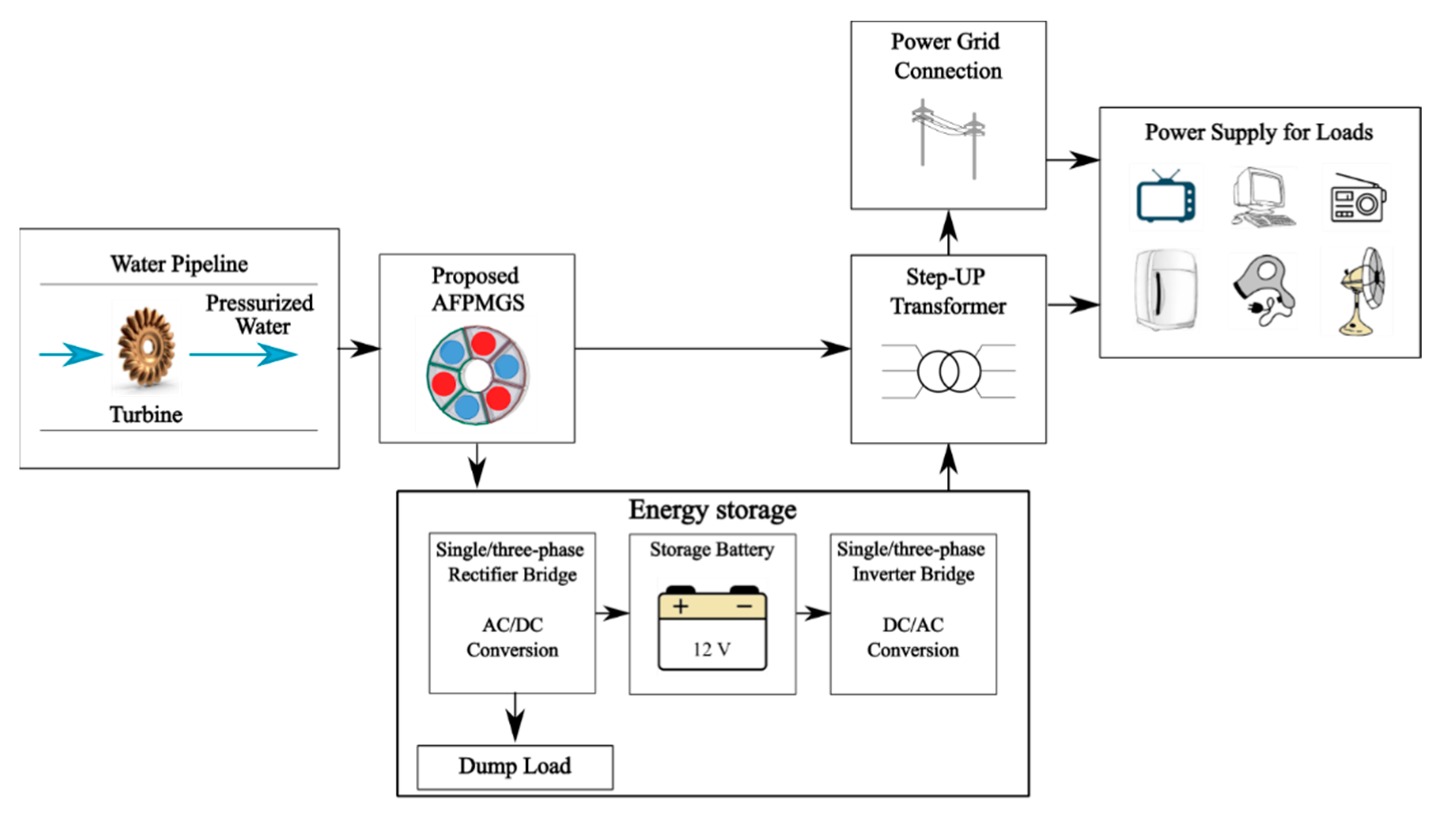
:1. Introduction
- Induction Generators (IG):
- a.
- squirrel-cage IG;
- b.
- doubly fed IG;
- Synchronous Generator (SG):
- c.
- brushed SG: with Direct Current (DC) or static excitation;
- d.
- brushless SG: with rotating diode bridge or Permanent Magnet (PM).
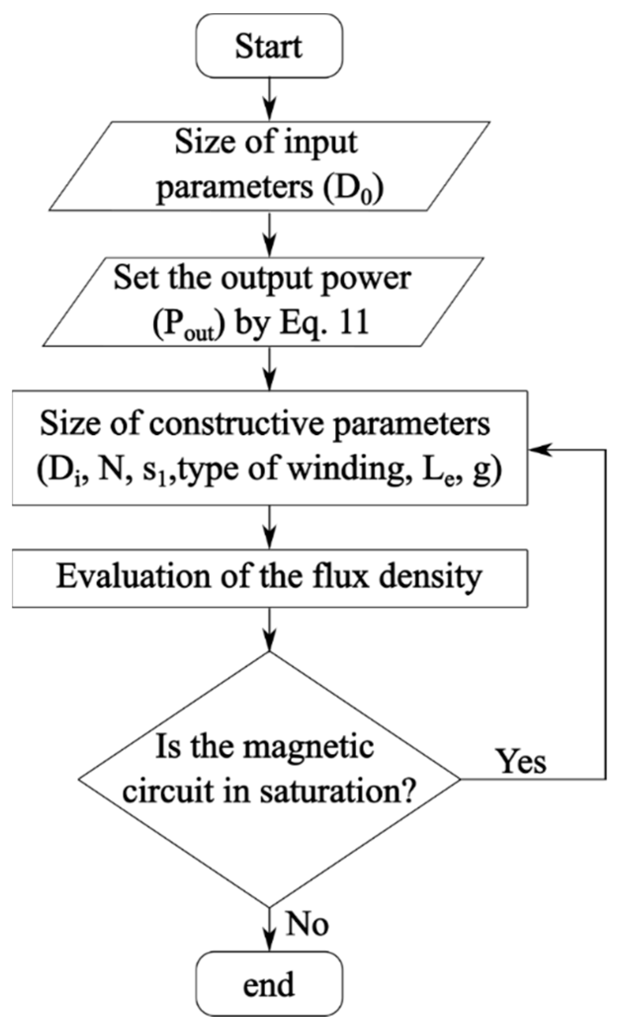
2. Mathematical Model of an Axial Flux Permanent Magnet Synchronous Generator for Pico Hydropower Application
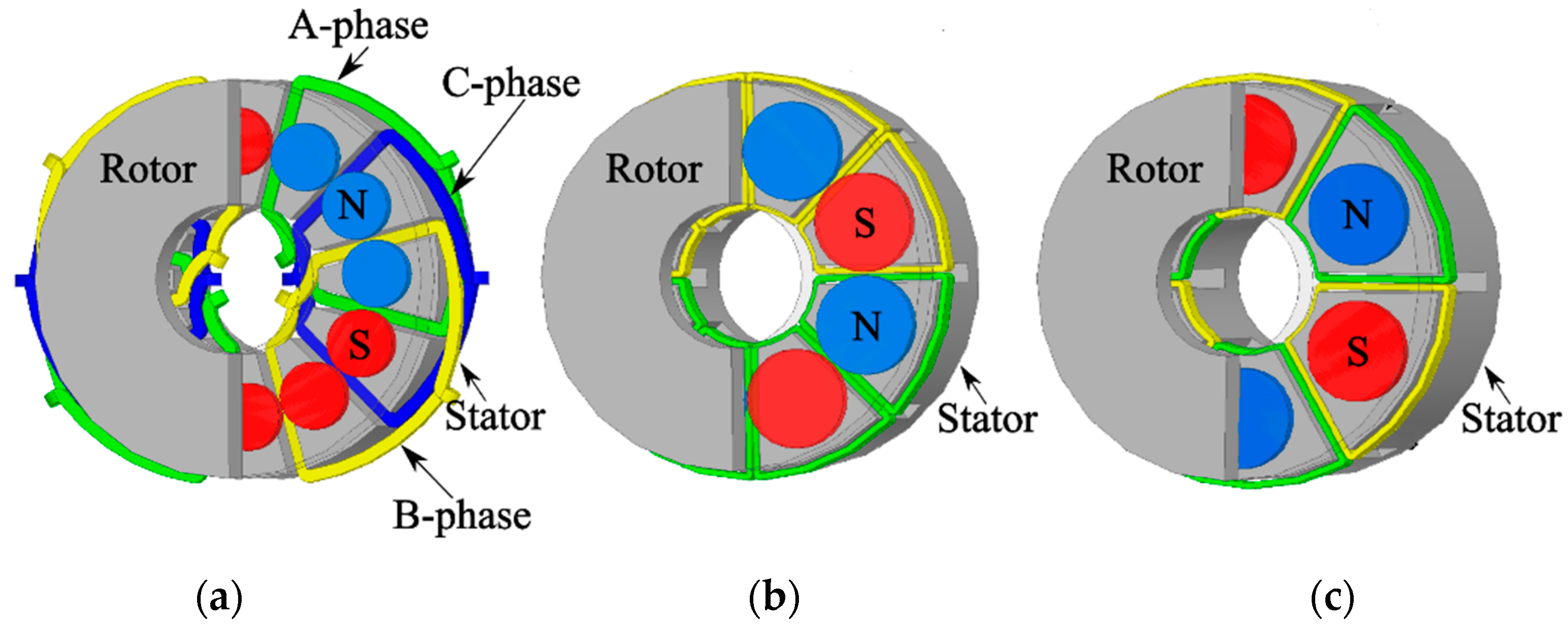
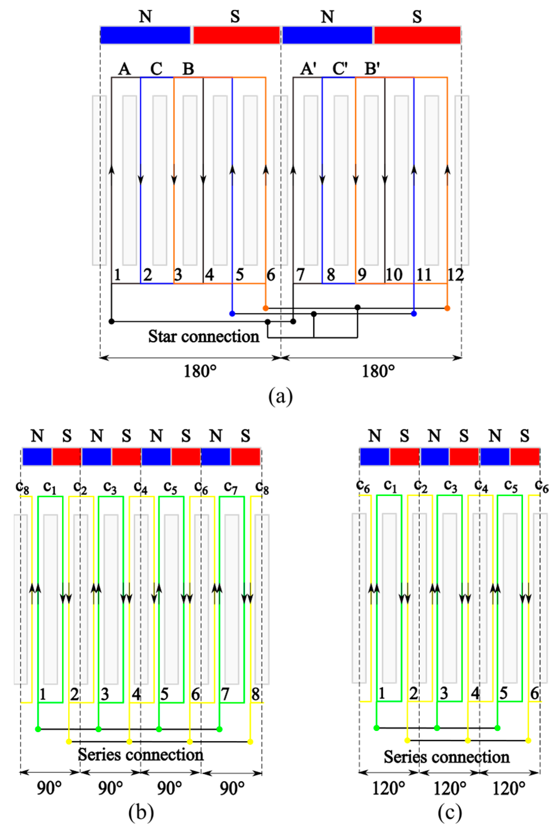
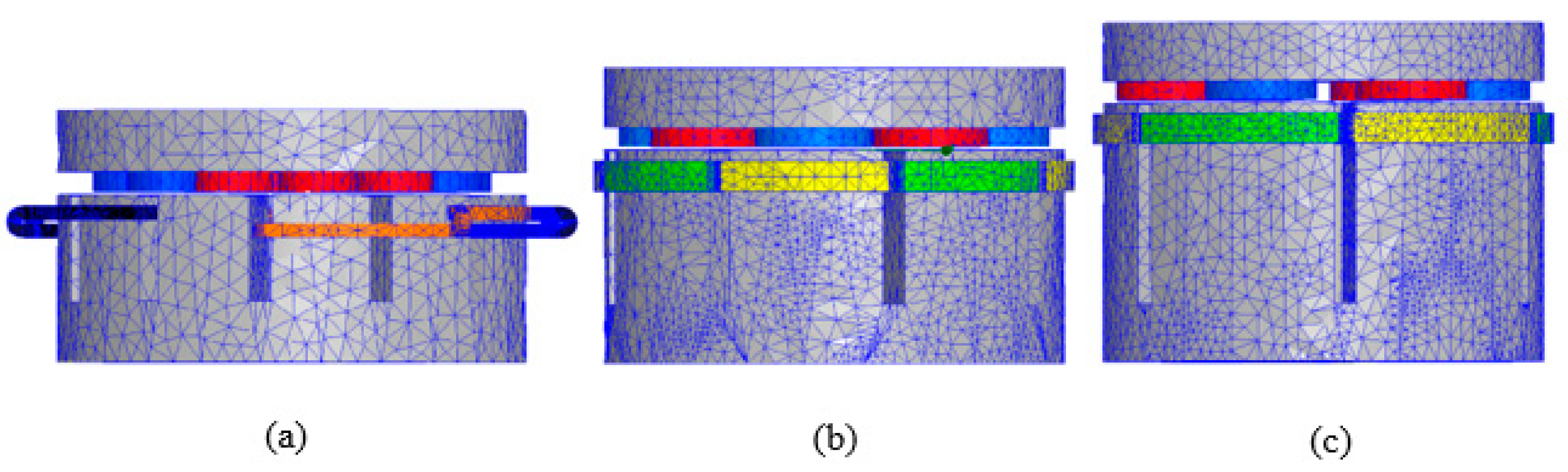
3. Parametrical Study of Three-Phase and Single-Phase Axial Flux Permanent Magnet Synchronous Generators for Pico Hydropower Application
- M1 is a three-phase AFPMGS with 2 polar pairs and single-layer concentrated windings;
- M2 is a single-phase AFPMGS with 4 polar pairs and double-layer concentrated windings;
- M3 is a single-phase AFPMGS with 3 polar pairs and double-layer concentrated windings.
- the slot fill factor, fr, assumed 0.7 for the easy manufacture of the windings and 1 to maximize the induced voltage on the coils and the magnetic flux produced;
- the thickness of the air-gap, g of 0.5 and 1 mm values used in industry [48] that limit the increase in air-gap reluctance and considers the manufacturing difficulties of a small machine increasing the ease of assembly and maintenance.
- the voltage magnitude induced in the stator winding;
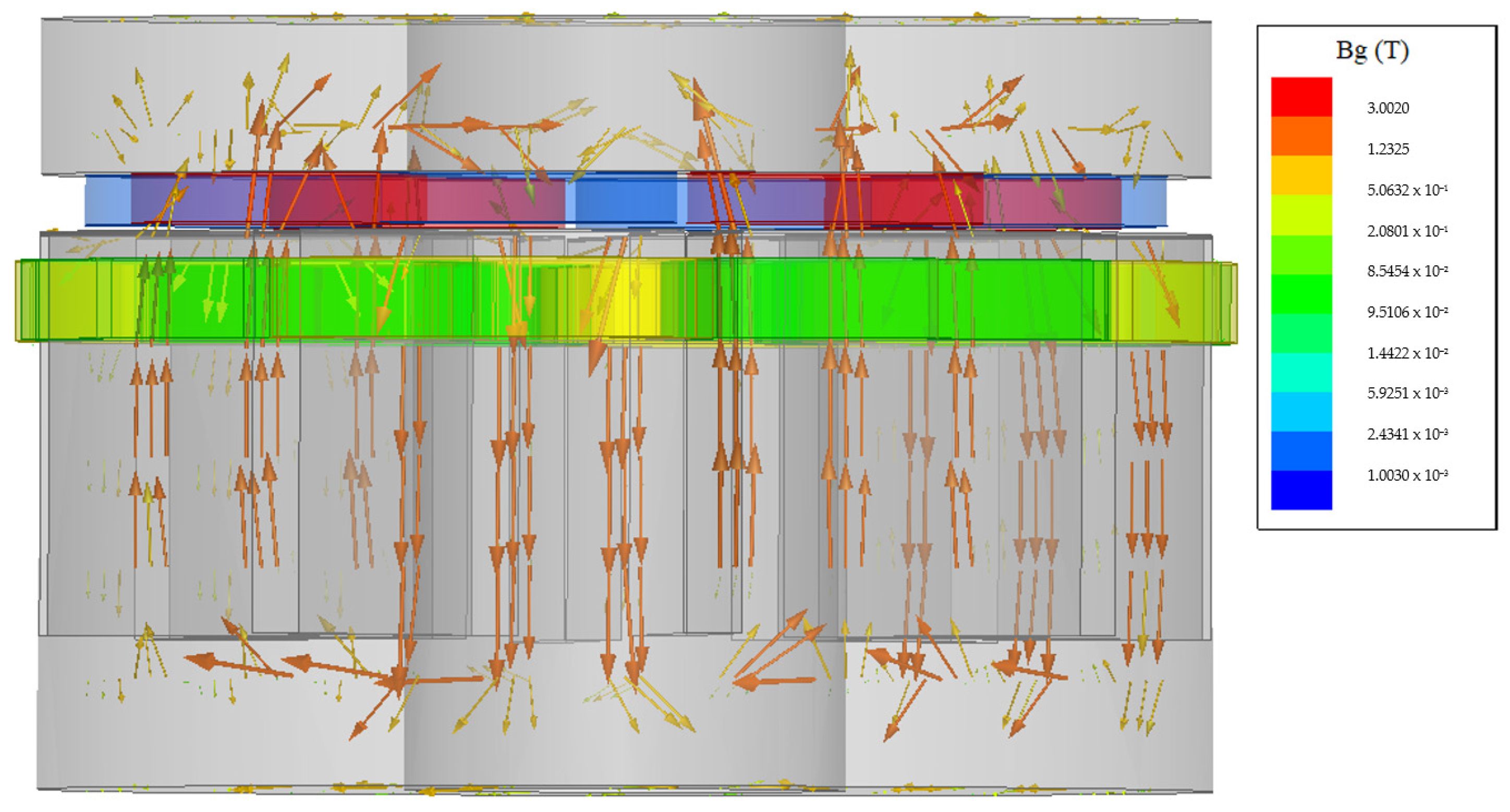
- the magnetic field value in the parts of the proposed generators.
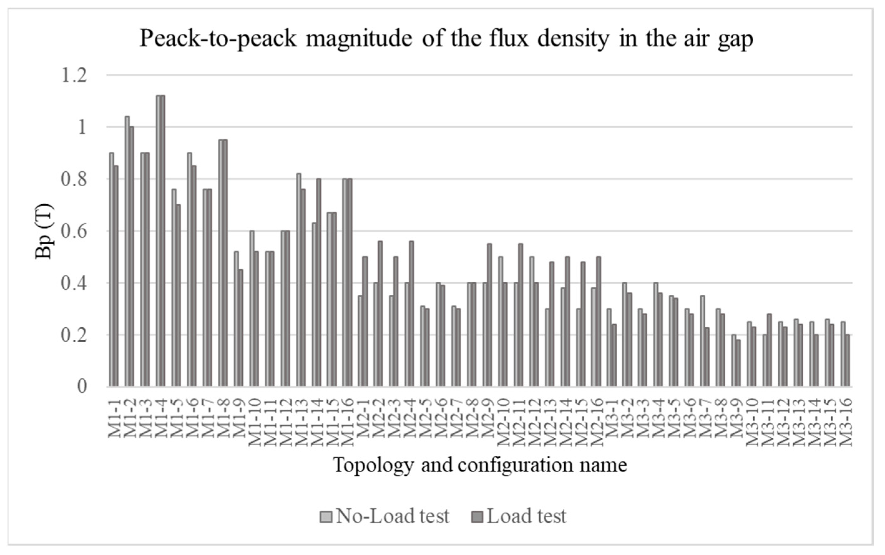
4. Results and Discussions
4.1. Assessment and Comparison of the Performance of the Proposed Topologies
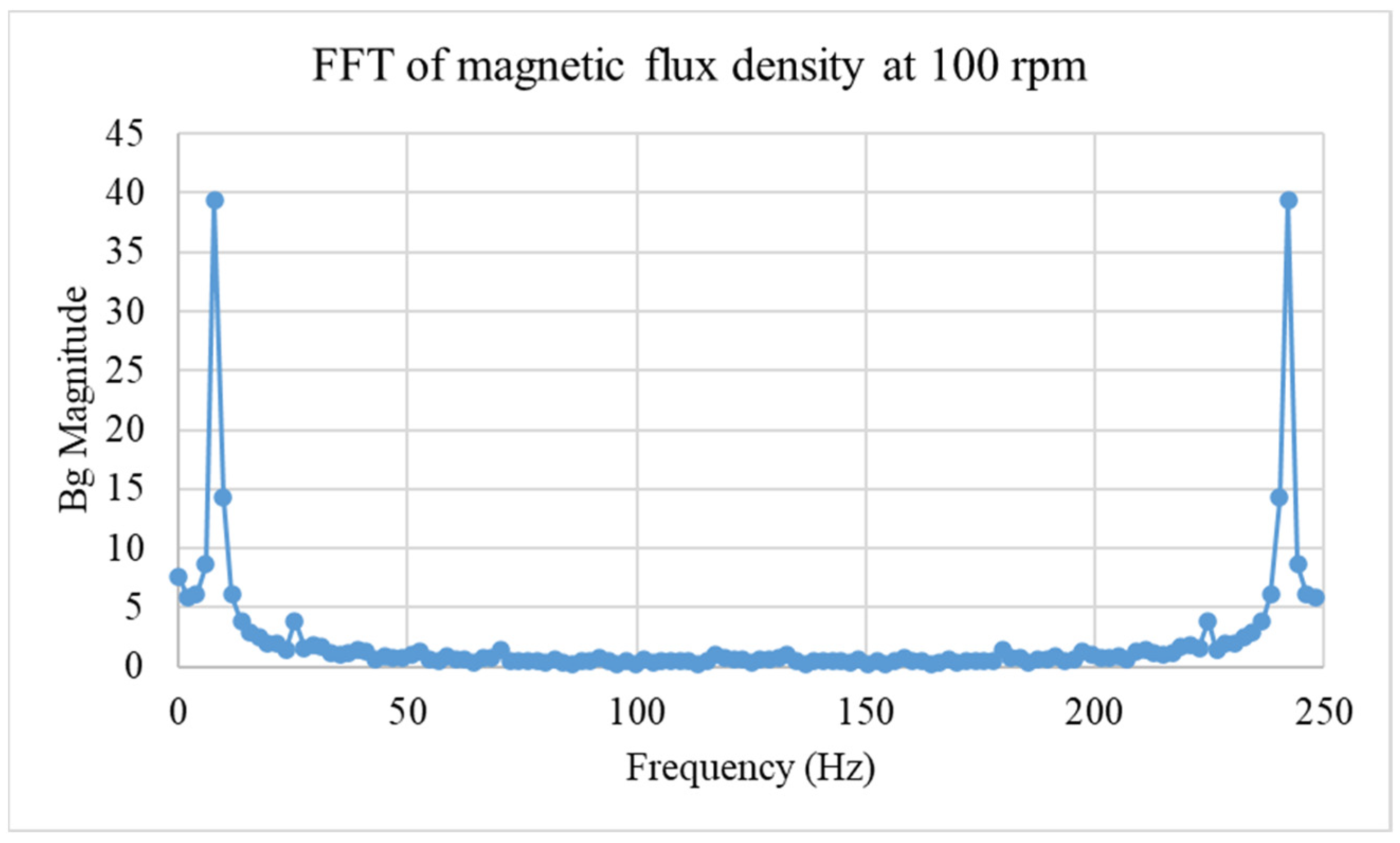
4.2. Analysis of the Highest Performance Topology under Different Working Conditions
5. Conclusions
Author Contributions
Funding
Acknowledgments
Conflicts of Interest
Nomenclature
| total electrical load (W); | |
| current density (A/mm2); | |
| rotor surface (mm2); | |
| flux density in air-gap (T); | |
| peak-to-peak magnitude of flux density in air-gap; | |
| remanence (T); | |
| outer diameter of the generators (mm); | |
| internal diameter of the generators (mm); | |
| diameter of PM (mm); | |
| phase air-gap EMF (V); | |
| er | rotor edge not occupied by PM (mm); |
| peak of phase air-gap EMF (V); | |
| f | frequency of the inverter (Hz); |
| slot fill factor; | |
| thickness of the air-gap (mm); | |
| coercive field of the PM (kA/m); | |
| stator current (A); | |
| i(t) | phase current (A); |
| peak of current (A); | |
| slot height (mm); | |
| slot width (mm); | |
| EMF factor; | |
| current waveform factor; | |
| aspect ratio coefficient of the type of machines; | |
| electrical power waveform factor; | |
| electrical loading ratio on the rotor and stator; | |
| height of the PM (mm); | |
| width of the PM (mm); | |
| thickness of the PM (mm); | |
| axial length of the generator (mm); | |
| number of phases; | |
| number of phases of each stator; | |
| winding number of turns; | |
| number of coils per phase; | |
| number of winding turns per phase; | |
| number of PM; | |
| number of layers of the winding; | |
| number of polar pairs; | |
| power output (W); | |
| number of slots per pole and per phase; | |
| average radius of the generator (mm); | |
| number of slots; | |
| cross-section of the slot (mm2); | |
| maximum conductor cross-section (mm2); | |
| period of one EMF cycle (s); | |
| peak-to-peak magnitude voltage induced in one phase of the stator winding. | |
| Greek Alphabet | |
| generator efficiency; | |
| ratio between the internal and outer diameter; | |
| electrical angle between the slots of the same phase (°); | |
| pole pitch; | |
| tooth pitch; | |
| vacuum permeability (H/m). | |
| Abbreviations | |
| 3-D | three dimensional; |
| AC | alternate current; |
| AFPMGS | axial flux permanent magnet synchronous generator; |
| NdFeB | neodymium iron boron earth magnets: |
| DC | direct current; |
| FEA | finite element analysis; |
| IG | Induction Generators; |
| PM | permanent magnet; |
| PMSG | permanent magnet synchronous generator; |
| Rpm | rotation per minutes; |
| SG | synchronous generator; |
| FFT | Fast Fourier Transform. |
References
- Balkhair, K.S.; Rahman, K.U. Sustainable and economical small-scale and low-head hydropower generation: A promising alternative potential solution for energy generation at local and regional scale. Appl. Energy 2017, 188, 378–391. [Google Scholar] [CrossRef]
- Liu, H.; Brown, T.; Andresen, G.B.; Schlachtberger, D.P.; Greiner, M. The role of hydro power, storage and transmission in the decarbonization of the Chinese power system. Appl. Energy 2019, 239, 1308–1321. [Google Scholar] [CrossRef]
- Qin, P.; Xu, H.; Liu, M.; Xiao, C.; Forrest, K.E.; Samuelsen, S.; Tarroja, B. Assessing concurrent effects of climate change on hydropower supply, electricity demand, and greenhouse gas emissions in the Upper Yangtze River Basin of China. Appl. Energy 2020, 279, 115694. [Google Scholar] [CrossRef]
- Basso, S.; Lazzaro, G.; Bovo, M.; Soulsby, C.; Botter, G. Water-energy-ecosystem nexus in small run-of-river hydropower: Optimal design and policy. Appl. Energy 2020, 280, 115936. [Google Scholar] [CrossRef]
- Patro, E.R.; De Michele, C.; Avanzi, F. Future perspectives of run-of-the-river hydropower and the impact of glaciers’ shrinkage: The case of Italian Alps. Appl. Energy 2018, 231, 699–713. [Google Scholar] [CrossRef]
- Gaudard, L.; Avanzi, F.; De Michele, C. Seasonal aspects of the energy-water nexus: The case of a run-of-the-river hydropower plant. Appl. Energy 2018, 210, 604–612. [Google Scholar] [CrossRef]
- International Hydropower Association (IHA). Hydropower Status Report 2020; International Hydropower Association (IHA): London, UK, 2020. [Google Scholar]
- International Hydropower Association (IHA). Hydropower Status Report 2015; International Hydropower Association (IHA): London, UK, 2015. [Google Scholar]
- Rapporto Statistico. Energia da Fonti Rinnovabili in Italia; Technical Report; Rapporto Statistico: Rome, Italy, 2015. [Google Scholar]
- Rapporto Statistico. Energia da Fonti Rinnovabili in Italia; Technical Report; Rapporto Statistico: Rome, Italy, 2018. [Google Scholar]
- Kuriqi, A.; Pinheiro, A.N.; Sordo-Ward, A.; Garrote, L. Flow regime aspects in determining environmental flows and maximising energy production at run-of-river hydropower plants. Appl. Energy 2019, 256, 113980. [Google Scholar] [CrossRef]
- Singh, P.; Nestmann, F. Experimental optimization of a free vortex propeller runner for micro hydro application. Exp. Therm. Fluid Sci. 2009, 33, 991–1002. [Google Scholar] [CrossRef]
- Carravetta, A.; Fecarotta, O.; Sinagra, M.; Tucciarelli, T. Cost-benefit analysis for hydropower production in water distribution networks by a pump as turbine. J. Water Resour. Plan. Manag. 2014, 140, 04014002. [Google Scholar] [CrossRef]
- Tarroja, B.; Forrest, K.; Chiang, F.; AghaKouchak, A.; Samuelsen, S. Implications of hydropower variability from climate change for a future, highly-renewable electric grid in California. Appl. Energy 2019, 237, 353–366. [Google Scholar] [CrossRef]
- Khomsah, A.; Sudjito; Wijono; Laksono, A.S. Pico-hydro as A Renewable Energy: Local Natural Resources and Equipment Availability in Efforts to Generate Electricity. In IOP Conference Series: Materials Science and Engineering; IOP Publishing Ltd.: Bristol, UK, 2019; Volume 462, p. 012047. [Google Scholar]
- AMusyafiq, A.A.; Ilahi, N.A.; Dewi, R.P.; Barokah, U. Simulation of Piko Hydro Power Generator Using Thread Turbine With 10 Watt Power. J. Jartel J. Jar. Telekomun. 2022, 12, 100–104. [Google Scholar]
- Venkatesh, P.; Viswanadha, V.; Sravan Kumar, K.; Ramesh, K. Design of Pico Hydro Power Plant Using an Impulse Turbine. In Advanced Manufacturing Systems and Innovative Product Design; Springer: Berlin/Heidelberg, Germany, 2021; pp. 251–260. [Google Scholar]
- Wahab, M.H.A.; Ching, K.B. Pico Hydro Generator Module for Domestic Water Pipe Fitting. Evol. Electr. Electron. Eng. 2022, 3, 321–331. [Google Scholar]
- Williams, A.; Simpson, R. Pico hydro—Reducing technical risks for rural electrification. Renew. Energy 2009, 34, 1986–1991. [Google Scholar] [CrossRef]
- Taylor, S.D.; Fuentes, M.; Green, J.; Rai, K. Stimulating the Market for Pico-Hydro in Ecuador; IT Power: Bristol, UK, 2003. [Google Scholar]
- Ming, B.; Liu, P.; Guo, S.; Zhang, X.; Feng, M.; Wang, X. Optimizing utility-scale photovoltaic power generation for integration into a hydropower reservoir by incorporating long- and short-term operational decisions. Appl. Energy 2017, 204, 432–445. [Google Scholar] [CrossRef]
- Maher, P.; Smith, N.; Williams, A. Assessment of pico hydro as an option for off-grid electrification in Kenya. Renew. Energy 2003, 28, 1357–1369. [Google Scholar] [CrossRef]
- Boukhezzar, B.; Siguerdidjane, H. Nonlinear control with wind estimation of a DFIG variable speed wind turbine for power capture optimization. Energy Convers. Manag. 2009, 50, 885–892. [Google Scholar] [CrossRef]
- Sarasúa, J.I.; Pérez-Díaz, J.I.; Wilhelmi, J.R.; Sánchez-Fernández, J.Á. Dynamic response and governor tuning of a long penstock pumped-storage hydropower plant equipped with a pump-turbine and a doubly fed induction generator. Energy Convers. Manag. 2015, 106, 151–164. [Google Scholar] [CrossRef]
- Naeini, V.; Ardebili, M. New axial flux PM less synchronous machine with concentrated DC field on stator. Int. J. Electr. Power Energy Syst. 2015, 67, 651–658. [Google Scholar] [CrossRef]
- Paul, S.; Chang, J. Model-based design of variable speed non-salient pole permanent magnet synchronous generator for urban water pipeline energy harvester. Int. J. Electr. Power Energy Syst. 2021, 125, 106402. [Google Scholar] [CrossRef]
- Barcaro, M.; Bianchi, N. Interior PM Machines Using Ferrite to Replace Rare-Earth Surface PM Machines. IEEE Trans. Ind. Appl. 2014, 50, 979–985. [Google Scholar] [CrossRef]
- Widyan, M.S.; Hanitsch, R.E. High-power density radial-flux permanent-magnet sinusoidal three-phase three-slot four-pole electrical generator. Int. J. Electr. Power Energy Syst. 2012, 43, 1221–1227. [Google Scholar] [CrossRef]
- Gieras, J.F.; Wang, R.-J.; Kamper, M.J. Axial Flux Permanent Magnet Brushless Machines, 2nd ed.; Springer Netherlands: Dordrecht, The Netherlands, 2008; pp. 1–362. [Google Scholar]
- Kurt, E.; Gör, H.; Demirtaş, M. Theoretical and experimental analyses of a single phase permanent magnet generator (PMG) with multiple cores having axial and radial directed fluxes. Energy Convers. Manag. 2014, 77, 163–172. [Google Scholar] [CrossRef]
- Flores, E.; Cumbajin, M.; Sanchez, P. Design of a synchronous generator of permanent magnets of radial flux for a pico-hydropower station. In Advances and Applications in Computer Science, Electronics and Industrial Engineering; Springer: Berlin/Heidelberg, Germany, 2021; pp. 135–151. [Google Scholar]
- Róowicz, S.; Goryca, Z.; Peczkis, G.; Korczak, A. Pico hydro generator as an effective source of renewable energy. Przeglkad Elektrotechniczny 2019, 4, 200–204. [Google Scholar] [CrossRef]
- Wannakarn, P.; Tanmaneeprasert, T.; Rugthaicharoencheep, N.; Nedphograw, S. Design and construction of axial flux permanent magnet generator for wind turbine generated DC voltage at rated power 1500 W. In Proceedings of the 2011 4th International Conference on Electric Utility Deregulation and Restructuring and Power Technologies (DRPT), Weihai, China, 6–9 July 2011; pp. 763–766. [Google Scholar]
- Safdar, I.; Sultan, S.; Raza, H.A.; Umer, M.; Ali, M. Empirical analysis of turbine and generator efficiency of a pico hydro system. Sustain. Energy Technol. Assess. 2020, 37, 100605. [Google Scholar] [CrossRef]
- Zainuddin, H.; Yahaya, M.S.; Lazi, J.M.; Basar, M.F.M.; Ibrahim, Z. Design and development of pico-hydro generation system for energy storage using consuming water distributed to houses. World Acad. Sci. Eng. Technol. 2009, 59, 154–159. [Google Scholar]
- Smith, N.P.A. Induction Generators for Stand-Alone Micro-Hydro Systems. In Proceedings of the IEEE International Conference on Power Electronics, Drives & Energy Systems for Industrial Growth (PEDES), New Delhi, India, 8–11 January 1996; Volume 2, pp. 669–673. [Google Scholar]
- Bozorgi, A.; Javidpour, E.; Riasi, A.; Nourbakhsh, A. Numerical and experimental study of using axial pump as turbine in Pico hydropower plants. Renew. Energy 2013, 53, 258–264. [Google Scholar] [CrossRef]
- Green, J.; Fuentes, M.; Rai, K.; Taylor, S. Stimulating the picohydropower market for low-income households in Ecuador; The World Bank: Washington, DC, USA, 2005. [Google Scholar]
- Chan, T.F.; Lai, L.L. An Axial-Flux Permanent-Magnet Synchronous Generator for a Direct-Coupled Wind-Turbine System. IEEE Trans. Energy Convers. 2007, 22, 86–94. [Google Scholar] [CrossRef]
- Kahourzade, S.; Mahmoudi, A.; Ping, H.W.; Uddin, M.N. A Comprehensive Review of Axial-Flux Permanent-Magnet Machines. Can. J. Electr. Comput. Eng. 2014, 37, 19–33. [Google Scholar] [CrossRef]
- Caricchi, F.; Crescimbini, F.; Honorati, O.; Bianco, G.L.; Santini, E. Performance of coreless-winding axial-flux permanent-magnet generator with power output at. IEEE Trans. Ind. Appl. 1998, 34, 1263–1269. [Google Scholar] [CrossRef]
- Laxminarayan, S.S.; Singh, M.; Saifee, A.H.; Mittal, A. Design, modeling and simulation of variable speed Axial Flux Permanent Magnet Wind Generator. Sustain. Energy Technol. Assess. 2017, 19, 114–124. [Google Scholar] [CrossRef]
- Huang, S.; Luo, J.; Leonardi, F.; Lipo, T. A comparison of power density for axial flux machines based on general purpose sizing equations. IEEE Trans. Energy Convers. 1999, 14, 185–192. [Google Scholar] [CrossRef]
- Kahourzade, S.; Mahmoudi, A.; Gandomkar, A.; Abd Rahim, N.; Ping, H.W.; Uddin, M.N. Design optimization and analysis of AFPM synchronous machine incorporating power density, thermal analysis, and back-EMF THD. Prog. Electromagn. Res. 2013, 136, 327–367. [Google Scholar] [CrossRef]
- Leong, Y.W.; Razali, A.R.; Priyandoko, G.; Kasim, N.I. Preliminary Studies on Number of Coil Turns per Phase and Distance between the Magnet Pairs for AFPM Ironless Electricity Generator. MATEC Web Conf. 2016, 38, 03003. [Google Scholar] [CrossRef] [Green Version]
- Kostenko, M.; Piotrovskii, L. Eectric Machines; Energiia: Leningrad, Russia, 1969. [Google Scholar]
- Huang, S.; Luo, J.; Leonardi, F.; Lipo, T. A general approach to sizing and power density equations for comparison of electrical machines. IEEE Trans. Ind. Appl. 1998, 34, 92–97. [Google Scholar] [CrossRef]
- Saavedra, H.; Romeral, L.; Riba, J.-R. Optimal Design of a Three-Phase AFPM for In-Wheel Electrical Traction. In Proceedings of the 2014 IEEE International Electric Vehicle Conference (IEVC), Florence, Italy, 17–19 December 2014. [Google Scholar]
- Huang, S.; Xie, G. Optimization of power density for axial-flux machine through generalized sizing equations. J. Shanghai Univ. 1997, 1, 232–236. (In English) [Google Scholar] [CrossRef]
- Puri, V.; Chauhan, Y.K.; Singh, N. A comparative design study and analysis of inner and outer rotor permanent magnet synchronous machine for power generation in vertical axis wind turbine using GSA and GSA-PSO. Sustain. Energy Technol. Assess. 2017, 23, 136–148. [Google Scholar] [CrossRef]
- Campbell, P. Principles of a Permanent-Magnet Axial-Field Dc Machine. Proc. Inst. Electr. Eng. 1974, 121, 1489–1494. [Google Scholar] [CrossRef]
- Caricchi, F.; Crescimbini, F.; Fedeli, E.; Noia, G. Design and construction of a wheel-directly-coupled axial-flux PM motor prototype for EVs. In Proceedings of the 1994 IEEE Industry Applications Society Annual Meeting, Denver, CO, USA, 2–6 October 1994; Volume 1, pp. 254–261. [Google Scholar]
- Jokinen, T.; Hrabovcova, V.; Pyrhonen, J. Design of Rotating Electrical Machines; John Wiley & Sons: Hoboken, NJ, USA, 2013. [Google Scholar]
- Meier, F.; Soulard, J. PMSMs with non-overlapping concentrated windings: Design guidelines and model references. Ecol. Veh. Renew. Energ. (EVER 09) 2009, 26–29. [Google Scholar]
- Cetin, E.; Daldaban, F. Analyzing the Profile Effects of the Various Magnet Shapes in Axial Flux PM Motors by Means of 3D-FEA. Electronics 2018, 7, 13. [Google Scholar] [CrossRef]
- Yahaya, E.A. Single layer winding of three phase induction motor. Int. J. Eng. Sci. 2013, 2, 8–13. [Google Scholar]
- Libert, F.; Soulard, J. Investigation on pole-slot combinations for permanent-magnet machines with concentrated windings. In Proceedings of the 16th International Conference on Electrical Machines, Lodz, Poland, 5–8 September 2004; pp. 530–535. [Google Scholar]
- Geng, W.; Zhang, Z. Analysis and Implementation of New Ironless Stator Axial-Flux Permanent Magnet Machine With Concentrated Nonoverlapping Windings. IEEE Trans. Energy Convers. 2018, 33, 1274–1284. [Google Scholar] [CrossRef]
- Ferreira, A.P.; Silva, A.M.; Costa, A.F. Prototype of an axial flux permanent magnet generator for wind energy systems applications. In Proceedings of the 2007 European Conference on Power Electronics and Applications (EPE), Aalborg, Denmark, 2–5 September 2007. [Google Scholar]
- Musolino, A.; Raugi, M.; Rizzo, R.; Tucci, M. Optimal Design of EMALS Based on a Double-Sided Tubular Linear Induction Motor. IEEE Trans. Plasma Sci. 2015, 43, 1326–1331. [Google Scholar] [CrossRef]
- Cipriani, G.; Corpora, M.; Di Dio, V.; Musolino, A.; Rizzo, R.; Sani, L. A comparison among different kinds of stator lamination in tubular linear machines. Prog. Electromagn. Res. M 2016, 50, 95–104. [Google Scholar] [CrossRef] [Green Version]
- Rizk, J.; Nagrial, M. Design of Permanent-Magnet Generators for Wind Turbines. In Proceedings of the IPEMC 2000: 3rd International Power Electronics and Motion Control Conference, Beijing, China, 15–18 August 2000; pp. 208–212. [Google Scholar]


| Mathematical Equation | Equation Number | Reference |
|---|---|---|
| (1) | [43] | |
| (2) | [39] | |
| (3) | [44] | |
| (4) | [45] | |
| (5) | [29] | |
| (6) | [46] | |
| (7) | [46] | |
| (8) | [46] | |
| (9) | [43] | |
| (10) | [47] |
| M1 | coil | ||||||||
| slot | 1-4 | 6-3 | 5-2 | 7-10 | 12-9 | 11-8 | |||
| M2 | coil | ||||||||
| slot | 1-2 | 3-2 | 3-4 | 4-5 | 5-6 | 7-6 | 7-8 | 1-8 | |
| M3 | coil | ||||||||
| slot | 1-2 | 3-2 | 3-4 | 5-4 | 5-6 | 1-6 |
| Topology Name | M1 | M2 | M3 |
|---|---|---|---|
| Type of phases | three-phase | single-phase | single-phase |
| Number of slots | 12 | 8 | 6 |
| Number of polar pairs | 2 | 4 | 3 |
| Pole pitch | 3 | 1 | 1 |
| Number of winding layers | single-layer | double-layer | double-layer |
| Cross-section of the winding conductor (mm2) | 0.8 | 1.4 | 1.4 |
| Number of coils | 6 | 8 | 6 |
| Number of coils in series per phase | 2 | 4 | 3 |
| Outer diameter (mm) | 71 | 71 | 71 |
| Slot height (mm) | 16 | 24.4 | 32.2 |
| Slot width (mm) | 5.3 | 8.0 | 10.7 |
| Stator length (mm) | 25.5 | 33.5 | 41.6 |
| Rotor length (mm) | 9.4 | 9.4 | 9.4 |
| Configuration Name | (mm) | (mm) | |||||
|---|---|---|---|---|---|---|---|
| 1 | 14 | 0.45 | 0.58 | 41.2 | 200/220/390 | 1 | 1 |
| 2 | 0.5 | ||||||
| 3 | 140/154/270 | 0.7 | 1 | ||||
| 4 | 0.5 | ||||||
| 5 | 12 | 0.56 | 0.63 | 44.7 | 200/220/390 | 1 | 1 |
| 6 | 0.5 | ||||||
| 7 | 140/154/270 | 0.7 | 1 | ||||
| 8 | 0.5 | ||||||
| 9 | 18 | 2.10 | 0.37 | 26.6 | 200/220/390 | 1 | 1 |
| 10 | 0.5 | ||||||
| 11 | 140/154/270 | 0.7 | 1 | ||||
| 12 | 0.5 | ||||||
| 13 | 10 | 0.32 | 0.70 | 49.7 | 200/220/390 | 1 | 1 |
| 14 | 0.5 | ||||||
| 15 | 140/154/270 | 0.7 | 1 | ||||
| 16 | 0.5 |
Publisher’s Note: MDPI stays neutral with regard to jurisdictional claims in published maps and institutional affiliations. |
© 2022 by the authors. Licensee MDPI, Basel, Switzerland. This article is an open access article distributed under the terms and conditions of the Creative Commons Attribution (CC BY) license (https://creativecommons.org/licenses/by/4.0/).
Share and Cite
Di Dio, V.; Cipriani, G.; Manno, D. Axial Flux Permanent Magnet Synchronous Generators for Pico Hydropower Application: A Parametrical Study. Energies 2022, 15, 6893. https://doi.org/10.3390/en15196893
Di Dio V, Cipriani G, Manno D. Axial Flux Permanent Magnet Synchronous Generators for Pico Hydropower Application: A Parametrical Study. Energies. 2022; 15(19):6893. https://doi.org/10.3390/en15196893
Chicago/Turabian StyleDi Dio, Vincenzo, Giovanni Cipriani, and Donatella Manno. 2022. "Axial Flux Permanent Magnet Synchronous Generators for Pico Hydropower Application: A Parametrical Study" Energies 15, no. 19: 6893. https://doi.org/10.3390/en15196893