Article

Energy Absorption Characteristics of Bio-Inspired Honeycomb Column Thin-Walled Structure under Low Strain Rate Uniaxial Compression Loading

1
School of Civil Engineering, Northeast Forestry University, Harbin 150040, China
2
Longjian Road and Bridge Company Limited, Harbin 150009, China
*
Authors to whom correspondence should be addressed.
Energies 2022, 15(19), 6957; https://doi.org/10.3390/en15196957
Submission received: 14 August 2022 / Revised: 30 August 2022 / Accepted: 13 September 2022 / Published: 22 September 2022
(This article belongs to the Section G: Energy and Buildings)

Abstract

:
The beetle’s elytra have the characteristics of light weight and high energy absorption (EA). In this paper, based on the internal structure of beetle elytra, two bio-inspired honeycomb column thin-walled structures (BHTS) I and II were fabricated by selective laser melting (SLM) technology in additive manufacturing (AM) in order to understand the possible influence of strain rate effect (SRE) on the BHTS under low speed uniaxial compression loading. The influence of three different SREs (0.001 s−1, 0.01 s−1 and 0.1 s−1) on the EA of BHTSs specimens during loading was discussed by means of out-of-plane uniaxial compression tests verified with numerical simulations. The experimental results show that SRE has a significant effect on the EA of BHTSs in low speed out-of-plane uniaxial compression tests: SRE can significantly increase the initial peak crushing force (PCF) and specific energy absorption (SEA) of all types of BHTS specimens. The average increase in PCF/SEA under SRE loading of 0.1 s−1 is 12.70%/9.79% and 17.63 %/11.60%, respectively, compared with 0.001 s−1 and 0.01 s−1. These research methods reduce the use of materials and improve the utilization rate of materials, which can provide important assistance for the design, manufacture and modeling of AM-based materials.

1. Introduction

With the excellent properties such as low density, high strength and high EA capacity [1], honeycomb structures (HS) are one of the common approaches to achieve light-weighting goals in practical engineering [2,3,4]. However, the results of several studies have shown that HS lead to a significant degradation of strength and stiffness when subjected to impact loading [5,6,7]. Therefore, the impact resistance of lightweight HS is receiving more and more attention. In recent years, the HS has attracted wide concern, especially in light weight and high strength research [8,9,10,11]. In industry, research has focused on structural crashworthiness and light-weighting, but these two diametrically opposed fields usually compete with each other [12].
In nature, organisms have evolved and naturally selected over millions of years to filter out biological structures and materials that are more suitable for the natural laws of the earth [13,14,15]. The beetle elytra are one of the most representative biological cuticles (Figure 1a), and the elytra structure has the advantage of being light-weight and hard, allowing the beetle to fly easily and protect itself [12]. Several scholars have investigated the internal microstructure of elytra [16,17], the experimental results indicate the existence of irregular HS and hollow columns within the elytra, and the hollow columns may be at the honeycomb walls or at the intersection of the honeycomb walls (Figure 1b); this HS is thought to have larger EA capacity. Several scholars have analyzed the internal microstructure of elytra and studied the mechanical properties of elytra [18,19], and several different classes of biological models have been developed on this basis [20,21].
SRE is usually present in the materials used to make HS, and different materials tend to have their own unique SRE [19,22,23]. In the experimental and numerical simulation of low-velocity impact tests, most scholars ignore the SRE in favor of simplifying the test and reducing the time cost [12,24]. Guo et al. [25] analyzed the compression damage mechanism of carbon/carbon composites using the multi-scale analysis method, found that the out-of-plane compression behavior of three-dimensional finely braided perforated carbon/carbon composites was sensitive to the strain rate, and the initial compress modulus, maximum stress, and strain at the maximum stress increased as the strain rate increased. Rosenthal et al. [26] studied the SRE of AlSi10Mg aluminum alloy specimens in the strain rate range of 2.77 × 10⁻⁶–2.77 × 10⁻¹ s−1 by SML, and they found that SLM-AlSi10Mg aluminum alloy has strain-rate-sensitive behavior: It was found to be strain-rate sensitive with significant changes to the flow stress and strain-hardening exponents with an increase in strain rate. Amir Hadadzadeh et al. [27] investigated the dynamic mechanics behavior of the material using Split Hopkinson Pressure Bar apparatus for aluminum alloy AlSi10Mg in the strain rate range of 800 s−1 and 3200 s−1. The alloy was found to be strain-rate sensitive, with yield strength increasing with increasing strain rate.
This way, the major contributions to plug in the existing research gaps in the present study are as follows:
  • The proposed BHTSs improved the mechanical performance of the conventional HS, increased the SEA of the manufacturing structure, reduced the mass of the stressed structure and the use of manufacturing materials, which saved resources.
  • The application of AM to the manufacture of complex cellular structures not only solves the problem of manufacturing such specimens by traditional industrial methods but also improves material utilization and saves energy.
  • In the numerical simulation of BHTSs, specific studies have been made in response to some scholars underestimating the SRE of aluminum alloy materials under low velocity uniaxial compression loading and do not consider the failure behavior of materials.
  • The results obtained can provide new ideas and a theoretical basis for the rational design of additive manufacturing porous biomorphic materials, and they have potential application prospects in the fields of protective equipment [8,9], resource utilization efficiency [28,29] and energy saving and emission reduction [30]. In addition, Table 1 lists some other contributions in these research areas.
The rest of this article is structured as follows. Section 2 briefly introduces the test materials and methods. In addition, this includes symbols and their description. Section 3 describes the test results, which verifies the feasibility of the study. Section 4 discusses the results and summarizes the study.

2. Materials and Methods

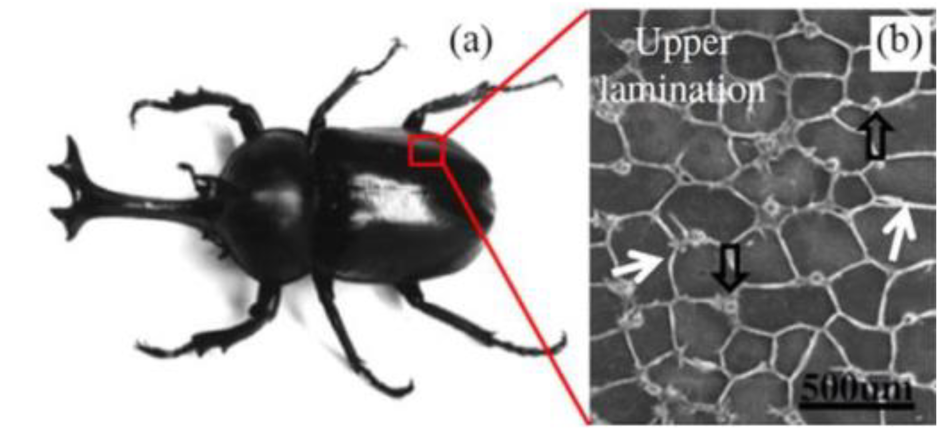
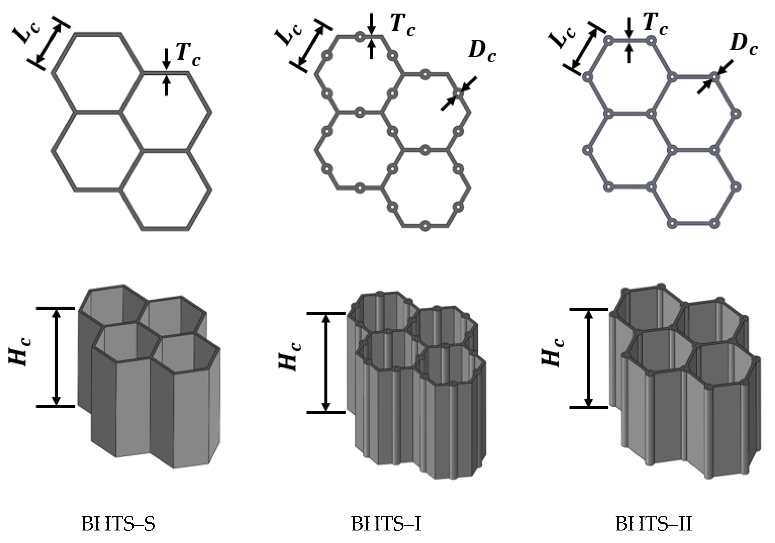
2.1. The Design of BHTSs

In this study, two different structural types of BHTS were designed from the internal structure of the beetle elytra, as shown in Figure 2. The bionic honeycomb structure (BHS) is a conventional HS without columns [12]. The design of BHTS is based on the thin-walled HS with columns of BHS. The dimensions of the HS are the same for different types, with side length, thickness, column diameter and height of 6 mm, 0.5 mm, 0.5 mm and 20 mm, respectively. Among them, BHTS–I hollow column and BHTS–II hollow column are added to the center of the honeycomb wall surface and the wall connection, respectively. Adopted Solidworks Pro.2020 according to Chinese specification [35], BHTS–S (i.e., BHS, treatment group), BHTS–I and BHTS–II were designed (Figure 2) with the dimensional parameters shown in Table 2. The notation used in full text is given in the Notation section.

2.2. Mechanical Properties of the Base Material for the BHTSs

In order to determine the mechanical properties of the BHTS material AlSi10Mg, the mechanical experiments of three-dimensional (3D)-printed porous structures by many scholars such as Ngoc San Ha, Thong M. Pham and so on [36] were referred to: the constitutive relation of the material is determined by uniaxial tensile test, and the finite element simulation is carried out using the obtained test data. The results show that the numerical model can effectively reflect the EA mechanism. According to the experimental concept of the above scholars, stretched dog-bone rods were designed according to ASTM E8/E8M standard [37] (Figure 3), 200 mm long, 20 mm wide at both ends and 12.5 mm wide in the middle, with a circular diameter of 63.5 mm and a 2 mm diameter hole in the middle. The tensile test was conducted on a Sansizongheng 50kN UTM5504GD universal testing machine with the proposed controlled tensile velocity distribution of 0.2 mm/s and 2 mm/s for each group of 5 specimens, corresponding to strain rates of 0.001 s−1 and 0.01 s−1.
The longitudinal elongation is measured with strain gauges, and the data from the strain gauges and the pressure measuring element are recorded by an additional computer. Figure 3 shows a typical stretching dog-bone rod tested. where the true stress-strain of the tensioned member is related to the engineering stress-strain curve as follows:
ε T = I n ( 1 + ε E )
σ T = σ E ( 1 + ε E )
In Equations (1) and (2), ε T , ε E , σ T , and σ E , are the true strain, engineering strain, true stress and engineering stress, respectively.
In the stretching process, the dog-bone rod was in the stage of linear elastic deformation before the proportional limit, and it entered the stage of nonlinear elastic deformation after reaching the proportional limit. With strain increasing, after reached the yield strength, the dog-bone rod changed from the elastic state to the plastic state, the material entered the strain-hardening stage, the tangent slope decreased continuously until reaching the peak stress. After strain increased, the stress gradually decreased, and the material entered the strain-softening stage, this stage was accompanied by local necking at the round hole of the dog-bone rod, i.e., strain localization and non-uniform distribution phenomenon, followed by fracture of the specimen. Since AlSi10Mg was Mises material, the stress state represented by the spherical stress tensor σ m was only the volume change of elasticity and did not cause plastic deformation. Therefore, the linear elastic deformation stage and nonlinear elastic deformation stage were removed during plastic deformation analysis (Figure 4).
After converting the engineering stress–strain into true stress–strain, the average ultimate stresses corresponding to 255 MPa and 270 MPa at 0.001 s−1 and 0.01 s−1 were obtained from the experiment. The material properties obtained from the experiment are shown in Table 3.

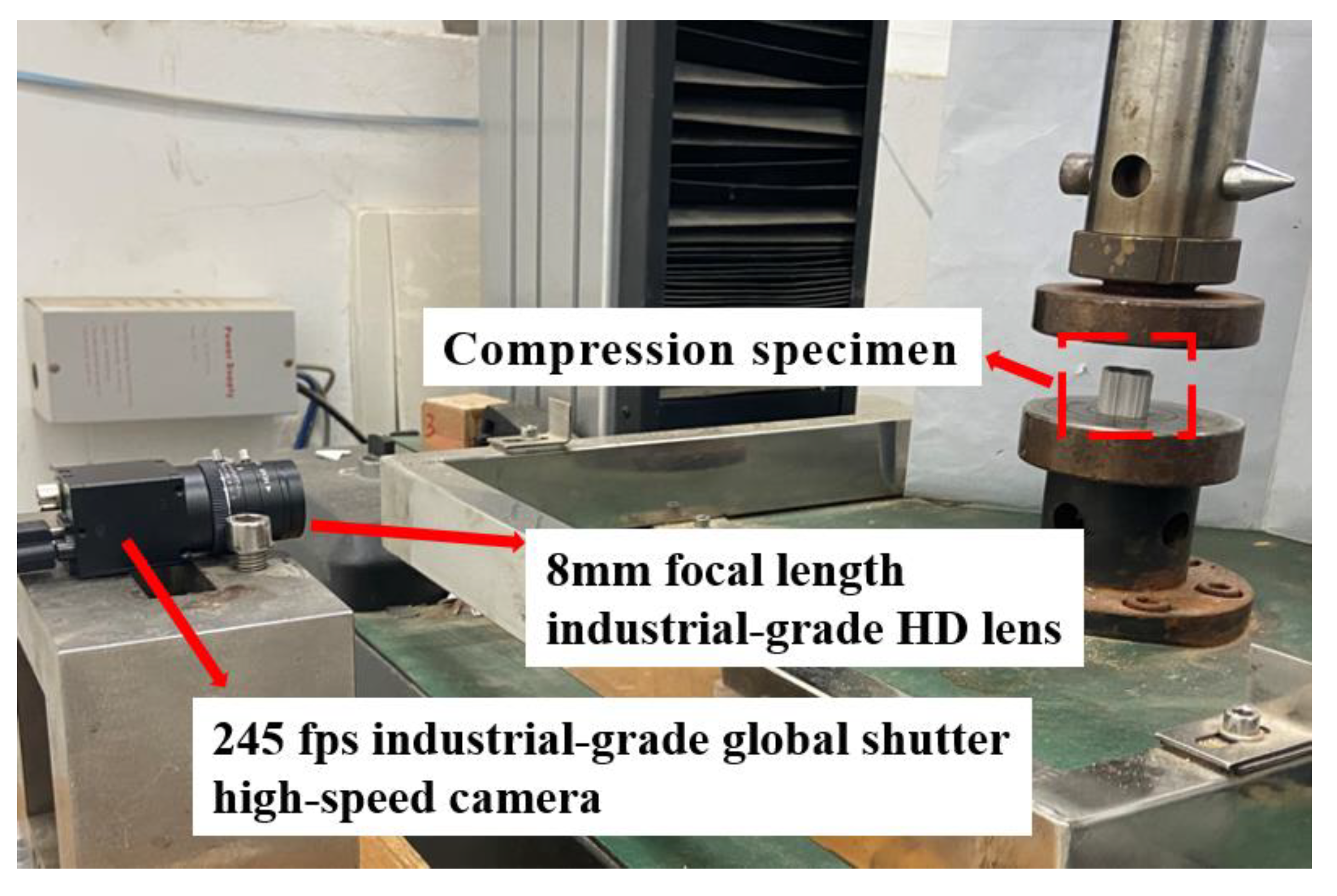
2.3. Out-of-Plane Uniaxial Compression Test

In recent years, the bio-cellular materials have become an important research area in the field of AM due to their complex lightweight design, and high EA properties under compressive loading [38,39,40]. Al-Si alloys have low density, high specific strength and good casting properties, and they are widely used in aerospace and automotive applications [41,42]. The Al-Si alloy AlSi10Mg was chosen as the build material for this study, using the design parameters described in Table 2. Each model was produced in an industrial grade ISLM-280 professional metal printer using SLM technology with high-part making accuracy and material utilization. The fabrication direction of the sample is out-of-plane direction, and Figure 5 shows the design model made by AM technology. The out-of-plane uniaxial compression response of the models (2 specimens per batch) was applied with a compression load at a constant rate using the Sansizongheng 50 kN UTM5504GD universal testing machine with the specimen types shown in Figure 2. The crushing force and displacement were recorded by an external computer. The specimens were conducted uniaxial compression at constant velocities of 0.02 mm/s, 0.2 mm/s and 2 mm/s, respectively. All nine groups of specimens were crushed to 75% of their original length. The force–displacement values were recorded and used for further analysis.
In order to study the effect of structural cross-sectional shapes on the performance of the honeycomb sandwich structure under low velocity impact, specimens with different geometric design parameters (BHTS–S, BHTS–I, BHTS–II) were tested and analyzed under uniaxial compression at strain rate design values of 0.001 s−1, 0.01 s−1 and 0.1 s−1, respectively. To completely capture the deformation process of BHTS in each test, an industrial-grade global shutter high-speed camera MV-SUA133GC-T with a maximum frame rate of 245 and an industrial-grade HD lens MV-LD-8-4M-G with a focal length of 8 mm was used to completely record the deformation process of the structure (Figure 6).

2.4. Assessment of the EA Performance

In this study, the magnitudes of all crushing parameters were calculated from the force–displacement curves. The PCF [42,43] is defined as the first peak force. The mean crushing force (MCF) [42,43,44] was calculated as the average crushing force in the displacement range of 3 to 15 mm. The formula for calculating MCF is:
MCF = 1 b a a b F d δ
In Equation (3), where a is 3 mm, b is 15 mm, d δ is the increment of compression displacement at the beginning of the densification state and F is the compression load.
EA capacity is an important index to characterize the performance of porous materials. In order to study the EA performance of different configurations, in terms of crushing force efficiency (CFE) [42,43,44,45] and SEA [46,47], two typical indexes were used as evaluation criteria to assess the EA properties of different types of BHTS at different low strain rates. CFE is defined as the ratio of MCF to PCF, as shown in Equation (4).
CFE = MCF PCF
EA [37,43] is the amount of energy dissipated by the specimen during the crushing process. It is determined from the area under the force–displacement curve according to Equation (5) and calculated from the displacement from 0 to b (15 mm).
EA = 0 b F d δ
Due to the high strength-to-weight ratio of the multi-cell structure, it is extremely important to consider the energy absorbed per unit mass of the material, so this is also known as the SEA, which is the EA divided by the mass ( m ) of the specimen, as shown in Equation (6).
S E A = E A m
Generally speaking, the higher the SEA, the better the EA capacity of the BHTS. In this paper, SEA is used to evaluate the EA capacity of a structure under out-of-plane compression.

2.5. Finite Element Model (FEM)

This study mainly uses the explicit finite element LS-DYNA commercial software for out-of-plane uniaxial loading of biomorphic cellular structures. LS-DYNA is a general finite element program for dynamic and nonlinear analysis [48]. Because the loading process is low-velocity loading, the temperature effect generated during high-speed loading can be disregarded. The aluminum is simulated using the Cowper–Symonds isotropic hardening model considering SRE [49,50], and the model’s expression is:
σ Y = [ 1 + ( ε ˙ C ) 1 P ] ( σ 0 + β E P ε P e f f )
In Equation (7), σ 0 is the initial yield stress. ε ˙ is the strain rate. β is the hardening parameter. C and P are strain rate parameters.   ε P e f f is the effective plastic strain, and E P   is the plastic hardening modulus
E P = d σ d ε p = E E t E E t
In Equation (8), ε p is the plastic strain, E is the modulus of elasticity, and E t is the tangent modulus [49,50,51,52]. The FEM was determined according to the data under each strain rate of the tensile test so that it can feed back the test values of other groups (Figure 4).
In the BHTS uniaxial compression test, the FEM consists of three parts, the fixed support steel plate, the upper end impact steel plate and the BHTSs in between (Figure 7, Figure 8 and Figure 9). The BHTSs model used *MAT_PLASTIC_KINEMATIC and defined the upper end impact plate and the lower end support plate as rigid bodies with *MAT_RIGID, and it adopted the reduced volume element. The calculation used *DEFINE_CURVE to set the motion path and then used *BOUNDARY_PRESCRIBED_MOTION_SET to define a linear displacement with time for the upper impact plate to ensure its uniform motion, the impact plate was constrained all displacements except the impact direction, and the fixed support plate was constrained all its displacements. The BHTSs were simulated using a full integrated membrane element Belytschko–Tsay [53,54], and the Al-Si alloy was simulated with considering SRE, as determined experimentally in Section 2.2, quadrilateral mesh was used. The single-sided automatic contact algorithm *CONTACT_AUTOMATIC_SINGLE_SURFACE was used for the contact of the HS model itself, the point-surface automatic contact algorithm *CONTACT_AUTOMATIC_NODES_TO_SURFACE [54,55] was chosen for the contact type between the HS and the upper surface of the fixed support plate, and the same algorithm is used for the contact type between the HS and the impact plate.

3. Results and Discussions

3.1. Deformation and Failure Modes

From Figure 7, it can be seen that under the uniaxial compression loading of BHTS–S, BHTS–I and BHTS–II specimens with the strain rate of 0.001 s−1, the damage location is mainly concentrated in the middle. Under strain rate loading of 0.01 s–1, the failure of the lower part is more obvious than that of the upper part. Under the strain rate loading of 0.1 s−1, the damage was concentrated in the middle and lower part of the specimen, and at the same time, the upper part of the specimen also showed expanded cracks, which was different from the loading phenomena of 0.001 s−1 and 0.01 s−1.
The out-of-plane uniaxial compression of the BHTS–S specimens were analyzed (Figure 7): under the 0.001 s−1 strain rate loading, the specimens were in the elastic deformation stage with the increase in the compression displacement, and the middle began to expand, when the lateral deformation of the specimens were regular. As the displacement continues to increase, the specimens were in the elastic nonlinear deformation stage, and the increasing range of transverse deformation was relatively large. At this time, both sides of the rib of the specimens appeared to undergo local buckling: the rib also because of the P-Δ effect (gravity second-order effect). Then, buckling collapse, and local flexural buckling also appeared. Displacement continued to increase, the integral specimens began to more obviously experience a unit cell form of shear failure followed by collapse. The material at the bottom and top of the specimens reached the failure strain, being gradually crushed into the folding and compacting stage, cycling in folding and crushing. Finally, the specimens were compressed into broken small pieces. Under a 0.01 s−1 strain rate loading, the specimens first appeared to undergo flexural buckling at the bottom of the loading process. As the displacement increases, the unit cell and the continuous form gradually collapse after shear failure, and the final specimens were compressed into broken small pieces. With the increase in displacement under 0.1 s−1 strain rate loading, the specimens first appeared to undergo flexure buckling at the bottom during loading with the increase in displacement. Then, it collapsed after continuous shear failure with the further increase in displacement loading, and finally, the specimens were compressed into small broken pieces.
The out-of-plane uniaxial compression of the BHTS–I specimens were analyzed (Figure 8): under 0.001 s−1 strain rate loading, the specimens underwent linear elastic deformation and nonlinear elastic deformation stages during the loading process. With the further increase in displacement, the integral specimens appeared to undergo torsional–flexural buckling, and then, it collapses after the shear failure of a unit cell. The material at the bottom and top of the specimens reached the failure strain and were gradually crushed into the folding and compacting stage, cycling in folding and crushing. Finally the specimens, were compressed into broken small pieces; under 0.01 s−1 strain rate loading, the specimens appeared to undergo flexural buckling in the middle of the loading process, and it gradually collapsed with the increase in displacement. Under the 0.1 s−1 strain rate loading, the specimens appeared torsional–flexural buckling at the middle of the loading process, and it gradually collapsed after the shear failure of a unit cell and continuous form with the increase in displacement, until finally, the specimens were compressed into broken small pieces.
The out-of-plane uniaxial compression of the BHTS–II specimens were analyzed (Figure 9): under 0.001 s−1 strain rate loading, the loading process was similar to that of BHTS–S and BHTS–I, and linear elastic deformation and nonlinear elastic deformation occurred one after another. With the increase in loading displacement, the integral specimen appeared to undergo flexural buckling, which was followed by collapse after shear failure of a unit cell. The material at the bottom and top of the specimens reached failure strain and were gradually crushed into the folding and compacting stage, cycling in folding and crushing, until finally, the specimens were compressed into broken small pieces. Under 0.01 s−1 strain rate loading, the specimen appeared to undergo flexural buckling at the middle and bottom during the loading process, and it gradually collapsed with the increase in displacement. Under 0.1 s−1 strain rate loading, the specimens appeared to undergo flexural buckling at the middle and bottom during the loading process, and it collapsed after the shear failure of a unit cell. Continuous form gradually appeared with the increase in displacement, until finally, the specimens were compressed into broken small pieces.

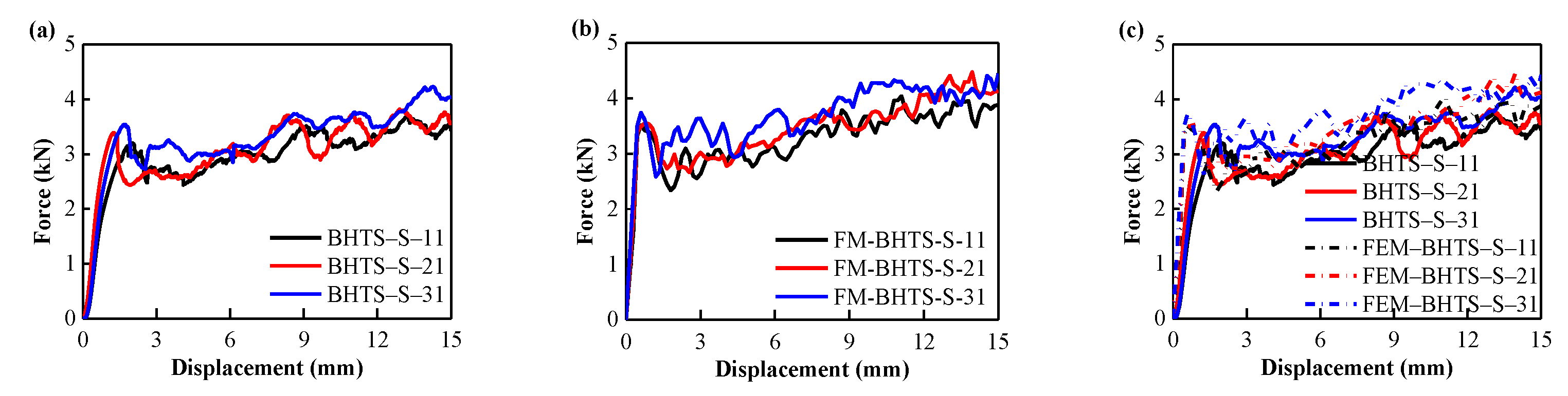
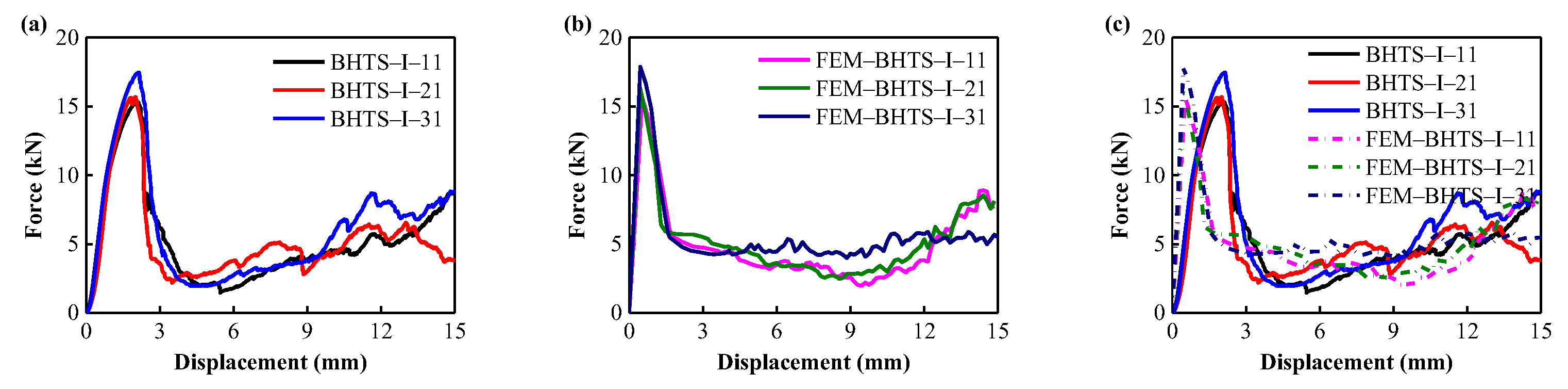
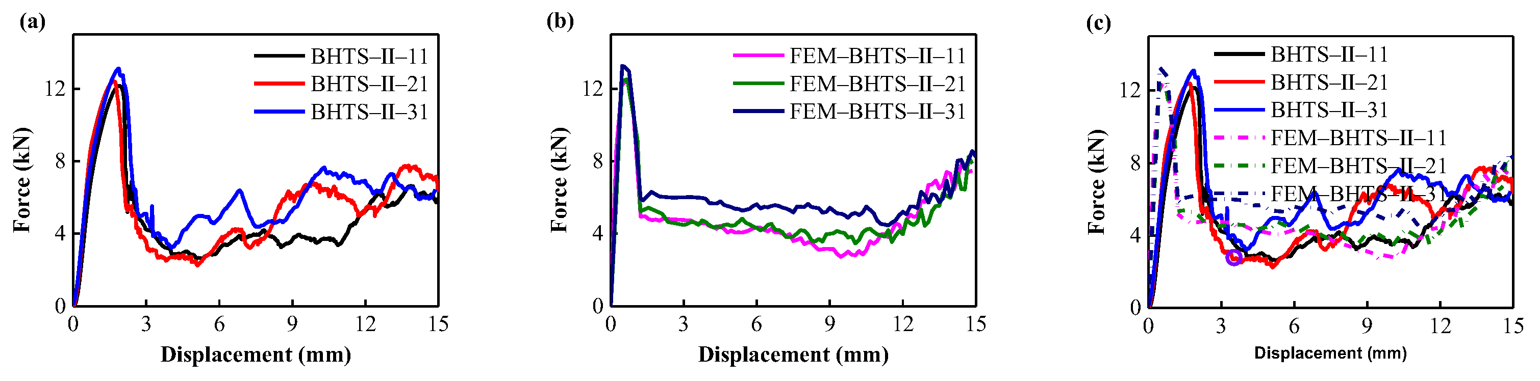
3.2. Validation of the FEM

The specimens numbers of the experiment conducted at different SRE levels for the three different design options BHTS–S, BHTS–I and BHTS–II are shown in Table 4. The impact load time curves are shown in Figure 10, Figure 11 and Figure 12.
The experimental tests showed that the specimens BHTS–S–11, BHTS–S–21 and BHTS–S–31 in panel 1 of BHTS–S (group 1) were in progressive crushing mode at strain rates of 0.001 s−1, 0.01 s−1 and 0.1 s−1, respectively (Figure 10). BHTS–S–11 loading at 0–0.62 mm was the linear elastic deformation stage; after exceeding the proportioned limit, at 0.62–2.02 mm, a more obvious geometric nonlinear deformation was caused by the presence of unavoidable lateral displacement during loading, and in the subsequent loading stage, the curve does not have a strengthened stage but rather a direct buckling. After the loading displacement reaches 2.02 mm the specimen collapsed due to shear failure after local flexural buckling, and the loading force decreased significantly; the initial folding occurs after the displacement was loaded at 2.61 mm, and the specimen became more dense after folding and enters the progressive crushing mode where buckling and strength damage coexist, and the strength curve appeared to rose when dense and fallen after buckling and strength damage coexist, and repeatedly during the loading process, it fluctuates until all compression was completed. The loading specimen of BHTS–S–21 and BHTS–S-31 was almost the same as those of BHTS–S–11, but there was a significant increase in PCF and MCF compared to BHTS–S–11. For the PCF comparison of the three specimens in panel 1 of BHTS–S, BHTS–S–21 is 5.63% larger than BHTS–S–11, while BHTS–S–31 is 10.31% larger than BHTS–S–11; in the MCF comparison, BHTS–S–21 is 9.16% larger than BHTS–S–11 and BHTS–S–31 is 16.48% larger than BHTS–S–11.
The force–displacement variation pattern of specimen BHTS–I–11 in panel 2 of group 2 during loading is similar to that of BHTS–S–11 of group 1 (Figure 11), but BHTS–I–11 has a more obvious torsional effect. Under the action of bending–torsion coupling, BHTS–I–11, BHTS–I–21 and BHTS–I–31 within the BHTS–I group undergo local torsional–flexural buckling, and the relationship between PCF and MCF are both BHTS–I–31>BHTS–S–21>BHTS–I–11. For the comparison of PCF of three specimens in panel 1 of BHTS–I, BHTS–I–21 was 2.42% larger than BHTS–I–11, while BHTS–I–31 was 14.12% larger than BHTS–I–11; in the comparison of MCF, BHTS–I–21 was 4.06% larger than BHTS–I–11, while BHTS–I–31 was 16.71% larger than BHTS–I–11.
The force–displacement variation pattern of BHTS–II specimens in panel 3 of group 3 during loading is similar to that of groups BHTS–S and BHTS–I (Figure 12). For the PCF comparison of the three specimens in panel 3 of BHTS–II, BHTS–II–21 is 1.73% larger than BHTS–II–11, while BHTS–II–31 is 7.91% larger than BHTS–II–11; in the MCF comparison, BHTS–II–21 is 11.70% larger than BHTS–II–11, while BHTS–II–31 is 23.15% larger than BHTS–II–11.
Figure 13 compared the PCF and MCF and finite element simulation results of the specimens in groups 1, 2 and 3. Comparing the average error values of the PCF and MCF test and numerical results for BHTS–S, BHTS–I and BHTS–II at a strain rate of 0.001–0.1 s−1, the PCF values of FEM were larger than the test by −4.97%; 2.63% and 0.899%, respectively; and the MCF values of FEM were larger than the test by 10.69%, 0.92% and 5.28% respectively. The results show that the experimental results are in good agreement with the FEM results, indicating that the numerical models have good reliability.

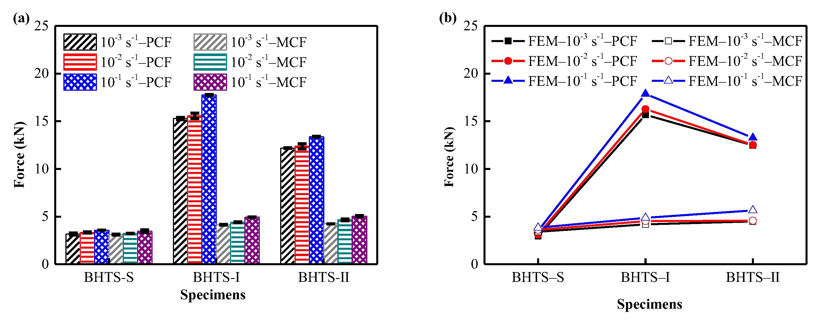
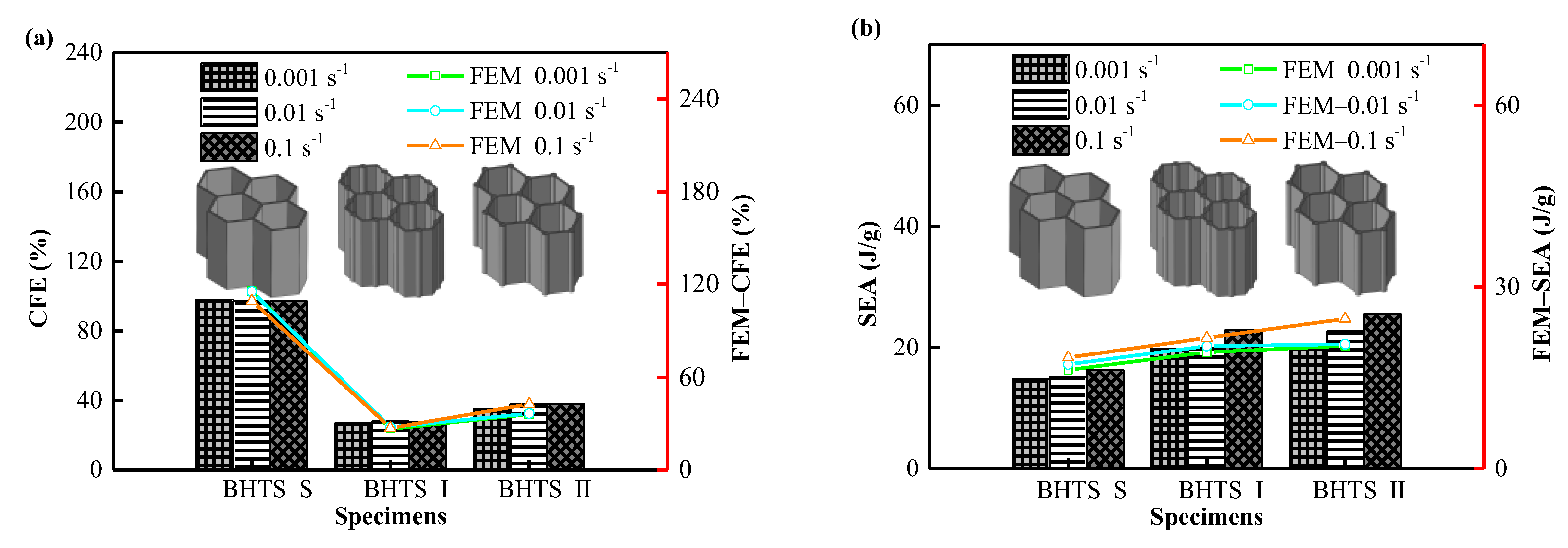
3.3. Mechanical Properties and EA Performance

Matlab [56], a business mathematics software produced by MathWorks, was used to compile calculation programs for data entry and calculation summary. Table 5a,b summarizes the PCF, MCF, CFE, EA, and SEA for all 3 groups of specimens. For comparison, we calculated the average values of MCF, CFE, EA and SEA for the duplicate specimens.

3.4. Comparison of EA Characteristics of BHTSs

The force versus displacement obtained from the numerical simulation was compared with the experimental results of each model, and the comparison of the out-of-plane mechanical properties obtained from the experiments and FEM is shown in Figure 14. From Figure 14a, it can be seen that the experimental results have a good agreement with the FEM results, which indicates that the numerical models have good reliability. Analyzing the CFE test results, the overall trend of CFE is BHTS–S > BHTS–II > BHTS–I: at 0.001 s−1 strain rate, the CFE of BHTS–S is 97.96%, which is 261.48% and 181.66% higher than BHTS–I and BHTS–II, respectively; at 0.01 s−1 strain rate, the CFE of BHTS–S is 97.02%, which is 243.19% and 157.28% higher than that of BHTS–I and BHTS–II, respectively; at 0.1 s−1 strain rate, the CFE of BHTS–S is 97.08%, which is 248.71% and 156.62% higher than that of BHTS–I and BHTS–II, respectively. Under the above three SREs, the average CFE of BHTS–S is 97.35%, which is 250.94% and 164.75% higher than the average CFE of BHTS–I and BHTS–II, respectively.
By analyzing the SEA test results (Figure 14b), the overall trend of SEA is BHTS–II > BHTS–I > BHTS–S: at 0.001 s−1 strain rate, the SEA of BHTS–II is 20.08, which is 36.23% and 1.26% higher than the BHTS–S and BHTS–I, respectively; at 0.01 s−1 strain rate, the SEA of BHTS–II is 22.65, which is 49.51% and 13.42% higher than BHTS–S and BHTS–I, respectively; at 0.1 s−1 strain rate, the SEA of BHTS–II is 25.51, which is 56.79% and 11.40% higher than the distribution of BHTS–S and BHTS–I. Combining the above three SREs, the average SEA of BHTS–II is 22.75, which is 47.82% and 8.85% higher than the average SEA of BHTS–S and BHTS–I, respectively.
The SEA analysis of the three structures of BHTS–S, BHTS–I and BHTS–II at 0.001 s−1, 0.01 s−1 and 0.1 s−1 strain rates yielded 0.1 s−1 > 0.01 s−1 > 0.001 s−1: the average SEA at 0.1 s−1 in BHTS–S is 16.27, which is larger than those at 0.01 s−1and 0.001 s−1 of 10.38% and 7.39%, respectively. The average SEA at 0.1 s−1 in BHTS–I is 22.90, which is 15.48% and 14.67% larger than that at 0.01 s−1and 0.001 s−1. The average SEA in BHTS–II is 25.51 at 0.1 s−1, which is 27.04% and 12.63% larger than those at 0.01 s−1 and 0.001 s−1. The whole average SEA for 0.1 s−1 is 21.56 under the combined three structural designs, which is 18.33% and 11.94% higher than the whole average SEA for 0.001 and 0.01 s−1, respectively.

4. Conclusions

In this paper, three different column-filling modes of bio-inspired honeycomb column thin-walled structure are proposed, and the influence caused by SRE on its energy absorption characteristics is the main subject of study. Tensile and compression tests and numerical analysis of each specimen were carried out, based on which the dynamic response of the structure during SRE loading at different range stages was calculated by the explicit finite element calculation software LS-DYNA. The following conclusions are drawn by comparing several important energy evaluation parameters PCF, CFE and SEA:
  • The designed cross-sectional shape had a very significant effect on the BHTS, and the bionic structure of the beetle elytra greatly enhanced the mean crushing force and energy absorption properties of the honeycomb structure.
  • The comparison of energy absorption characteristics of BHTS by test shows that the strain rate effect has a significant effect on the energy absorption capacity of BHTS under axial impact load.
  • The finite element simulation results are in good agreement with the experimental results. This research method can provide an important reference for the design, manufacture and modeling of materials based on BHTS.
  • The finite element simulation and lightweight BHTSs design concept used in the design process of BHTSs greatly reduce the material consumption in the design stage; the additive manufacturing with high utilization rate of materials used in the test process optimizes the use efficiency of materials, conforms to the concept of energy saving and emission reduction, and has potential promotion value.

Author Contributions

H.X.: Funding acquisition, Conceptualization, Investigation, Methodology, Validation, Writing—original draft, Writing—review & editing. Q.S.: Supervision. Y.L.: Data Curation. All authors have read and agreed to the published version of the manuscript.

Funding

This research was funded by [Fundamental Research Funds for the Central universities] grant number [2572019AB16] and the APC was funded by [H.X].

Acknowledgments

The financial support provided by the Fundamental Research Funds for the Central universities, (Project No. 2572019AB16) is highly appreciated.

Conflicts of Interest

The authors declare that they have no known competing financial interests or personal relationships that could have appeared to influence the work reported in this paper.

Notations

T c Cell wall thickness σ 0 Initial yield stress
H c Column height ε ˙ Strain rate
L c Cell side length β Hardening parameter
D c Column diameter C , P Strain rate parameter
ε T True strain ε P e f f Effective plastic strain
ε E Engineering strain E P Plastic hardening modulus
σ T True stress ε p Plastic strain
σ E Engineering stress E Elastic modulus
σ m Spherical stress tensor E t Tangent modulus

References

  1. He, W.; Yao, L.; Meng, X.; Sun, G.; Xie, D.; Liu, J. Effect of structural parameters on low-velocity impact behavior of aluminum honeycomb sandwich structures with CFRP face sheets. Thin-Walled Struct. 2019, 137, 411–432. [Google Scholar] [CrossRef]
  2. Riccio, A.; Raimondo, A.; Saputo, S.; Sellitto, A.; Battaglia, M.; Petrone, G. A numerical study on the impact behaviour of natural fibres made honeycomb cores. Compos. Struct. 2018, 202, 909–916. [Google Scholar] [CrossRef]
  3. Sun, M.; Wowk, D.; Mechefske, C.; Kim, I.Y. An analytical study of the plasticity of sandwich honeycomb panels subjected to low-velocity impact. Compos. Part B Eng. 2019, 168, 121–128. [Google Scholar] [CrossRef]
  4. Zhang, J.; Ye, Y.; Qin, Q.; Wang, T. Low-velocity impact of sandwich beams with fibre-metal laminate face-sheets. Compos. Sci. Technol. 2018, 168, 152–159. [Google Scholar] [CrossRef]
  5. Siivola, J.T.; Minakuchi, S.; Takeda, N. Unloading response prediction of indentation loaded foam core sandwich structures using extended foam material model with tensile hardening. Compos. Part B Eng. 2016, 84, 71–82. [Google Scholar] [CrossRef]
  6. Feng, D.; Aymerich, F. Damage prediction in composite sandwich panels subjected to low-velocity impact. Compos. Part A Appl. Sci. Manuf. 2013, 52, 12–22. [Google Scholar] [CrossRef]
  7. di Caprio, F.; Cristillo, D.; Saputo, S.; Guida, M.; Riccio, A. Crashworthiness of wing leading edges under bird impact event. Compos. Struct. 2019, 216, 39–52. [Google Scholar] [CrossRef]
  8. Ufodike, C.O.; Wang, H.; Ahmed, M.F.; Dolzyk, G.; Jung, S. Design and modeling of bamboo biomorphic structure for in-plane energy absorption improvement. Mater. Des. 2021, 205, 109736. [Google Scholar] [CrossRef]
  9. Ufodike, C.O. Exploring the Wood Material Properties and Structures for Engineering Application; Florida Agricultural and Mechanical University: Tallahassee, FL, USA, 2020. [Google Scholar]
  10. du Plessis, A.; Broeckhoven, C.; Yadroitsava, I.; Yadroitsev, I.; Hands, C.H.; Kunju, R.; Bhate, D. Beautiful and functional: A review of biomimetic design in additive manufacturing. Addit. Manuf. 2019, 27, 408–427. [Google Scholar] [CrossRef]
  11. Zhang, Q.; Yang, X.; Li, P.; Huang, G.; Feng, S.; Shen, C.; Han, B.; Zhang, X.; Jin, F.; Xu, F. Bioinspired engineering of honeycomb structure–Using nature to inspire human innovation. Prog. Mater. Sci. 2015, 74, 332–400. [Google Scholar] [CrossRef]
  12. Hao, P.; Du, J. Energy absorption characteristics of bio-inspired honeycomb column thin-walled structure under impact loading. J. Mech. Behav. Biomed. Mater. 2018, 79, 301–308. [Google Scholar] [CrossRef] [PubMed]
  13. Naleway, S.E.; Porter, M.M.; McKittrick, J.; Meyers, M.A. Structural design elements in biological materials: Application to bioinspiration. Adv. Mater. 2015, 27, 5455–5476. [Google Scholar] [CrossRef] [PubMed]
  14. Naleway, S.E.; Taylor, J.R.; Porter, M.M.; Meyers, M.A.; McKittrick, J. Structure and mechanical properties of selected protective systems in marine organisms. Mater. Sci. Eng. C 2016, 59, 1143–1167. [Google Scholar] [CrossRef]
  15. Xiang, J.; Du, J.; Li, D.; Liu, K. Aerodynamic performance of the locust wing in gliding mode at low Reynolds number. J. Bionic Eng. 2016, 13, 249–260. [Google Scholar] [CrossRef]
  16. Chen, J.; Dai, G.; Xu, Y.; Iwamoto, M. Basic study of biomimetic composite materials in the forewings of beetles. Mater. Sci. Eng. A 2008, 483, 625–628. [Google Scholar] [CrossRef]
  17. Sun, M.; Liang, A.; Watson, G.S.; Watson, J.A.; Zheng, Y.; Jiang, L. Compound Microstructures and Wax Layer of Beetle Elytral Surfaces and Their Influence on Wetting Properties. PLoS ONE 2012, 7, e46710. [Google Scholar] [CrossRef]
  18. Chen, J.; He, C.; Gu, C.; Liu, J.; Mi, C.; Guo, S. Compressive and flexural properties of biomimetic integrated honeycomb plates. Mater. Des. 2014, 64, 214–220. [Google Scholar] [CrossRef]
  19. Sun, J.; Ling, M.; Wang, Y.; Chen, D.; Zhang, S.; Tong, J.; Wang, S. Quasi-static and dynamic nanoindentation of some selected biomaterials. J. Bionic Eng. 2014, 11, 144–150. [Google Scholar] [CrossRef]
  20. Chen, J.; Xie, J.; Zhu, H.; Guan, S.; Wu, G.; Noori, M.N.; Guo, S. Integrated honeycomb structure of a beetle forewing and its imitation. Mater. Sci. Eng. C 2012, 32, 613–618. [Google Scholar] [CrossRef]
  21. Clark, A.J.; Triblehorn, J.D. Mechanical properties of the cuticles of three cockroach species that differ in their wind-evoked escape behavior. PeerJ 2014, 2, e501. [Google Scholar] [CrossRef] [Green Version]
  22. Lomakin, J.; Huber, P.A.; Eichler, C.; Arakane, Y.; Kramer, K.J.; Beeman, R.W.; Kanost, M.R.; Gehrke, S.H. Mechanical properties of the beetle elytron, a biological composite material. Biomacromolecules 2011, 12, 321–335. [Google Scholar] [CrossRef]
  23. Sun, J.-Y.; Tong, J.; Ma, Y.-H. Nanomechanical behaviours of cuticle of three kinds of beetle. J. Bionic Eng. 2008, 5, 152–157. [Google Scholar] [CrossRef]
  24. Xiang, J.; Du, J. Energy absorption characteristics of bio-inspired honeycomb structure under axial impact loading. Mater. Sci. Eng. A 2017, 696, 283–289. [Google Scholar] [CrossRef]
  25. Guo, F.; Fei, Q.; Li, Y.; Gupta, N. Dynamic Out-of-Plane Compressive Failure Mechanism of Carbon/Carbon Composite: Strain Rate Effect on the Defect Propagation and Microstructure Failure. J. Eng. Mater. Technol. 2021, 143, 1–31. [Google Scholar]
  26. Rosenthal, I.; Stern, A.; Frage, N. Strain rate sensitivity and fracture mechanism of AlSi10Mg parts produced by selective laser melting. Mater. Sci. Eng. A 2017, 682, 509–517. [Google Scholar] [CrossRef]
  27. Hadadzadeh, A.; Amirkhiz, B.S.; Odeshi, A.; Li, J.; Mohammadi, M. Role of hierarchical microstructure of additively manufactured AlSi10Mg on dynamic loading behavior. Addit. Manuf. 2019, 28, 1–13. [Google Scholar] [CrossRef]
  28. Sharma, P.; Said, Z.; Kumar, A.; Nižetić, S.; Pandey, A.; Hoang, A.T.; Huang, Z.; Afzal, A.; Li, C.; Le, A.T.; et al. Recent advances in machine learning research for nanofluid-based heat transfer in renewable energy system. Energy Fuels 2022, 36, 6626–6658. [Google Scholar] [CrossRef]
  29. Said, Z.; Sharma, P.; Elavarasan, R.M.; Tiwari, A.K.; Rathod, M.K. Exploring the specific heat capacity of water-based hybrid nanofluids for solar energy applications: A comparative evaluation of modern ensemble machine learning techniques. J. Energy Storage 2022, 54, 105230. [Google Scholar] [CrossRef]
  30. Yadav, D.; Singh, R.; Kumar, A.; Sarkar, B. Reduction of Pollution through Sustainable and Flexible Production by Controlling By-Products. J. Environ. Inform. 2022. [Google Scholar] [CrossRef]
  31. Gu, C.L.; He, C.L.; Liu, J.X.; Chen, J.X. Trial Manufacture of Bionic Honeycomb Plates and their bending properties. In Applied Mechanics and Materials; Trans Tech Publ: Stafa-Zurich, Switzerland, 2014; Volume 461, pp. 101–107. [Google Scholar]
  32. Xiang, J.; Du, J.; Li, D.; Zhen, C. Functional morphology and structural characteristics of wings of the ladybird beetle, Coccinella septempunctata (L.). Microsc. Res. Tech. 2016, 79, 550–556. [Google Scholar] [CrossRef]
  33. Saufi, S.; Zuhri, M.Y.M.; Dezaki, M.L.; Sapuan, S.M.; Ilyas, R.A.; As’Arry, A.; Ariffin, M.K.A.; Bodaghi, M. Compression Behaviour of Bio-Inspired Honeycomb Reinforced Starfish Shape Structures Using 3D Printing Technology. Polymers 2021, 13, 4388. [Google Scholar] [CrossRef] [PubMed]
  34. Dubicki, A.; Zglobicka, I.; Kurzydłowski, K.J. Investigation of Energy-Absorbing Properties of a Bio-Inspired Structure. Metals 2021, 11, 881. [Google Scholar] [CrossRef]
  35. China National Standardization Administration Committee. Test Method for Flatwise Compression Properties of Sandwich Constructions or Cores; China Standard Publishing House: Beijing, China, 2005. (In Chinese) [Google Scholar]
  36. Ha, N.S.; Pham, T.M.; Tran, T.T.; Hao, H.; Lu, G. Mechanical properties and energy absorption of bio-inspired hierarchical circular honeycomb. Compos. Part B Eng. 2022, 236, 109818. [Google Scholar] [CrossRef]
  37. Hamid, W.L.H.W.A.; Aminanda, Y.; Dawood, M.S. Experimental Investigation on the Energy Absorption Capability of Foam-Filled Nomex Honeycomb Structure. In Applied Mechanics and Materials; Trans Tech Publ: Stafa-Zurich, Switzerland, 2013; Volume 393, pp. 460–466. [Google Scholar]
  38. Ahangar, P.; Cooke, M.E.; Weber, M.H.; Rosenzweig, D.H. Current biomedical applications of 3D printing and additive manufacturing. Appl. Sci. 2019, 9, 1713. [Google Scholar] [CrossRef]
  39. Gibson, I.; Rosen, D.; Stucker, B.; Khorasani, M. Development of additive manufacturing technology. In Additive Manufacturing technologies; Springer: Berlin/Heidelberg, Germany, 2021; pp. 23–51. [Google Scholar]
  40. Dizon, J.R.C.; Espera, A.H., Jr.; Chen, Q.; Advincula, R.C. Mechanical characterization of 3D-printed polymers. Addit. Manuf. 2018, 20, 44–67. [Google Scholar] [CrossRef]
  41. Laurençon, M.; de Resseguier, T.; Loison, D.; Baillargeat, J.; Ngnekou, J.D.; Nadot, Y. Effects of additive manufacturing on the dynamic response of AlSi10Mg to laser shock loading. Mater. Sci. Eng. A 2019, 748, 407–417. [Google Scholar] [CrossRef]
  42. Ahmed, N.; Xue, P.; Zafar, N. Dynamic axial crushing of bitubular tubes with curvy polygonal inner-tube sections. Int. J. Comput. Mater. Sci. Eng. 2017, 6, 1750024. [Google Scholar] [CrossRef]
  43. Palanivelu, S.; van Paepegem, W.; Degrieck, J.; Kakogiannis, D. Parametric study of crushing parameters and failure patterns of pultruded composite tubes using cohesive elements and seam, Part I: Central delamination and triggering modelling. Polym. Test. 2010, 29, 729–741. [Google Scholar] [CrossRef]
  44. Tran, T.; Ton, T. Lateral crushing behaviour and theoretical prediction of thin-walled rectangular and square tubes. Compos. Struct. 2016, 154, 374–384. [Google Scholar] [CrossRef]
  45. Dong, J.-H.; Wang, Y.-J.; Jin, F.-N.; Fan, H.-L. Crushing behaviors of buckling-induced metallic meta-lattice structures. Def. Technol. 2022, 18, 1301–1310. [Google Scholar] [CrossRef]
  46. Lee, J.-H.; Wang, L.; Boyce, M.C.; Thomas, E.L. Periodic bicontinuous composites for high specific energy absorption. Nano Lett. 2012, 12, 4392–4396. [Google Scholar] [CrossRef] [PubMed]
  47. Ryzińska, G.; David, M.; Prusty, G.; Tarasiuk, J.; Wroński, S. Effect of fibre architecture on the specific energy absorption in carbon epoxy composite tubes under progressive crushing. Compos. Struct. 2019, 227, 111292. [Google Scholar] [CrossRef]
  48. Yin, H.; Huang, X.; Scarpa, F.; Wen, G.; Chen, Y.; Zhang, C. In-plane crashworthiness of bio-inspired hierarchical honeycombs. Compos. Struct. 2018, 192, 516–527. [Google Scholar] [CrossRef]
  49. Available online: http://lsdyna.ru/wp-content/uploads/2018/10/LS-DYNA-KEYWORD-USERS-MANUAL-VOL2.pdf./ (accessed on 12 September 2022).
  50. Jones, N. Structural Impact; Cambridge University Press: Cambridge, UK, 2011. [Google Scholar]
  51. Wan, Y.; Zhu, L.; Fang, H.; Liu, W.; Mao, Y. Experimental testing and numerical simulations of ship impact on axially loaded reinforced concrete piers. Int. J. Impact Eng. 2019, 125, 246–262. [Google Scholar] [CrossRef]
  52. Wang, H.; Yang, B.; Chen, K.; Elchalakani, M. Parametric analysis and simplified approach for steel-framed subassemblies with reverse channel connection under falling-debris impact. Eng. Struct. 2020, 225, 111263. [Google Scholar] [CrossRef]
  53. Gunes, R.; Arslan, K. Development of numerical realistic model for predicting low-velocity impact response of aluminium honeycomb sandwich structures. J. Sandw. Struct. Mater. 2016, 18, 95–112. [Google Scholar] [CrossRef]
  54. Xie, S.; Jing, K.; Zhou, H.; Liu, X. Mechanical properties of Nomex honeycomb sandwich panels under dynamic impact. Compos. Struct. 2020, 235, 111814. [Google Scholar] [CrossRef]
  55. Available online: http://lsdyna.ru/wp-content/uploads/2018/10/LS-DYNA-KEYWORD-USERS-MANUAL-VOL1.pdf./ (accessed on 12 September 2022).
  56. Grant, M.; Boyd, S. CVX: Matlab Software for Disciplined Convex Programming, Version 2.0 Beta. Available online: http://cvxr.com/cvx (accessed on 20 September 2020).
Figure 1. The beetle and its microstructure: (a) the beetle Allomyrina dichotoma; (b) micromorphology of HS with columns [12].
Energies 15 06957 g001
Figure 2. Types of BHTS.
Energies 15 06957 g002
Figure 3. Strain gauges arrangement, unit: mm.
Energies 15 06957 g003
Figure 4. True stress–strain curves of AlSi10Mg specimens at different strain rates.
Energies 15 06957 g004
Figure 5. BHTSs out-of-plane uniaxial compression loading diagram: (a) BHTS–S; (b) BHTS–I; (c) BHTS–II.
Energies 15 06957 g005
Figure 6. Schematic diagram of the high-speed camera site layout.
Energies 15 06957 g006
Figure 7. The crushing process of BHTS–S under various strain rate loading.
Energies 15 06957 g007
Figure 8. The crushing process of BHTS–I under various strain rate loading.
Energies 15 06957 g008
Figure 9. The crushing process of BHTS–II under various strain rate loading.
Energies 15 06957 g009
Figure 10. Typical response curves of BHTS–S at each strain rate: (a) curves of experimental; (b) curves of FEM; (c) comparison between experimental and FEM.
Energies 15 06957 g010
Figure 11. Typical response curves of BHTS–I at each strain rate: (a) curves of experimental; (b) curves of FEM; (c) comparison between experimental and FEM.
Energies 15 06957 g011
Figure 12. Typical response curves of BHTS–II at each strain rate: (a) curves of experimental; (b) curves of FEM; (c) comparison between experimental and FEM.
Energies 15 06957 g012
Figure 13. Comparison of PCF and MCF average values of experiment and FEM: (a) experiment; (b) FEM.
Energies 15 06957 g013
Figure 14. EA assessment indexes of BHTSs at each strain rate: (a) average CFE values of test and FEM; (b) average SEA values of test and FEM.
Energies 15 06957 g014
Table 1. Comparison of present study with some major contributions.
AuthorsMajor FindingsResearch Gaps
Chen et al. (2008) [16] The microstructures and bio-structure design techniques in the forewing of the Allomyrina dichotoma beetle were examined.Not verified by test.
Chen et al. (2012) [20]Based on the research of the beetle forewing structure, a method of constructing honeycomb panel in integral form was designed.No model test study.
Chen et al. (2014) [18]Compression and bending properties of a novel bionic integrated honeycomb panel were studied.Manufacturing accuracy needs to be improved.
Sun et al. (2014) [19]Investigation of the viscoelastic behavior of some biomaterials (nacre, cattle horn and beetle cuticle) at lamellar length scales using quasi-static and dynamic nanoindentation techniques in the materials’ Transverse Direction (TD) and Longitudinal Direction (LD).No corresponding engineering structures were designed and tested.
Clark and Triblehorn. (2014) [21]The structure and material properties of insect cuticle were studied.No model test study.
Gu et al. (2014) [31]The bionic honeycomb panel was trial-produced, and its mechanical properties were discussed.Manufacturing accuracy needs to be improved.
Xiang et al. (2016) [32]Surface morphology and the cross-sectional microstructure of the wings were presented.Not verified by test.
Rosenthal et al. (2016) [26]Strain-rate-sensitive behavior of SLM-AlSi10Mg aluminum alloy in the strain rate range of 2.77 × 10⁻⁶–2.77 × 10⁻¹.No numerical model was established.
Xiang and Du. (2017) [24]Two BHTS were proposed.SRE and material failure not considered.
Hao and Du. (2018) [12]Three BHTS were proposed.SRE and material failure not considered.
Hadadzadeh et al. (2019) [27]Aluminum alloy AlSi10Mg is strain rate sensitive in the strain-rate range of 800 s–1 and 3200 s–1.No numerical model was established.
Guo et al. (2021) [25]The out-of-plane compressive behavior of carbon/carbon composites is sensitive to strain rate in the strain rate range of 0.0001 s–1 and 1000 s–1.The designed structure is not based on bionic principles.
Saufi et al. (2021) [33]The EA capacity and high strength of the bionic structure were studied by fused deposition modeling technology.SRE not considered.
Dubicki et al. (2021) [34]The structure of the simulated diatom truncated body retains its similarity to natural shells, and 3D printing and compression tests were performed to develop new energy-absorbing materials using bionic methods.SRE not considered.
Present studyTwo BHTS models with different filling modes proposed by Hao and Du were used to fabricated SLM-AlSi10Mg specimens by AM technology. The comparative study was carried out under three different low strain rates of 0.001 s−1, 0.01 s−1 and 0.1 s−1, the failure mode and EA were evaluated. A reasonable numerical model were established by using explicit finite element software LS-DYNA.
Table 2. BHTS parameters of the study.
Specimen Label Cell   Wall   Thickness   T c   ( mm ) Column Height H c   ( mm ) Cell Side Length
L c   ( mm )
Column   Diameter   D c   ( mm )
BHTS–S0.520.06.0/
BHTS–I0.520.06.00.5
BHTS–II0.520.06.00.5
Table 3. Material properties of AlSi10Mg alloy.
DensityYoung’s ModulusPoisson’s RatioInitial Yield Strength
2670 kg/m369 ± 5 GPa0.3220 ± 10 MPa
Table 4. BHTS test set and FEM number.
Panel NumberTypeStrain Rate
0.001 s−10.01 s−10.1 s−1
1SpecimenBHTS–S–11BHTS–S–21BHTS–S–31
FEMFEM-BHTS–SFEM-BHTS–SFEM-BHTS–S
2SpecimenBHTS–I–11BHTS–I–21BHTS–I–31
FEMFEM-BHTS–IFEM-BHTS–IFEM-BHTS–I
3SpecimenBHTS–II–11BHTS–II–21BHTS–II–31
FEMFEM-BHTS–IIFEM-BHTS–IIFEM-BHTS–II
The first numbers (1, 2 and 3) which are after the last letters in the specimen refer to the velocity/specimen length ratio of 10–3 s–1, 10–2 s–1 and 10–1 s–1 respectively while the second number refers to the repeated test.
Table 5. Values of each EA property of BHTS under different strain rates.
(a)
Group
Number
DetailSpecimenVelocity/Specimen LengthVelocity
(mm/s)
Mass
(g)
PCF
(kN)
MCF
(kN)
1BHTS–S1110−30.023.023.203.13
1210−30.022.973.153.09
2110−20.23.033.383.24
2210−20.23.033.273.21
3110−123.013.533.48
3210−123.033.613.45
2BHTS–I1110−30.023.8515.304.19
1210−30.023.8815.264.09
2110−20.23.8815.674.36
2210−20.23.8515.444.43
3110−123.8717.464.89
3210−123.8518.044.99
3BHTS–II1110−30.023.6312.134.19
2110−30.023.6612.244.29
2110−20.23.6212.344.68
2210−20.23.6212.404.65
3110−123.6413.095.16
3210−123.6113.644.94
(b)
Group
Number
DetailSpecimenCFE
(%)
EA
(J)
SEA
(J/g)
Average Value
PCF
(kN)
MCF
(kN)
CFE
(%)
EA
(J)
SEA
(J/g)
1BHTS–S1197.8144.2914.673.183.1197.9644.1314.74
1298.1043.9614.80
2195.8645.9515.173.333.2397.0245.9015.15
2298.1745.8515.13
3198.5849.2116.353.573.4797.0849.1216.27
3295.5749.0316.18
2BHTS–I1127.3977.8920.2315.284.1427.1076.6319.83
1226.8175.3719.43
2127.8478.1420.1415.564.4028.2777.1019.95
2228.7076.0519.75
3128.0390.0223.2617.754.9427.8488.3922.90
3227.6486.7522.53
3BHTS–II1134.5071.8419.7912.194.2434.7873.1720.08
2135.0674.5020.36
2137.8981.6622.5612.374.6737.7181.9922.65
2237.5382.3122.74
3139.4192.2225.3413.375.0537.8392.4525.51
3236.2592.6825.67
The first numbers (1, 2 and 3) which are after the last letters in the specimen refer to the velocity/specimen length ratio of 10–3 s–1, 10–2 s–1 and 10–1 s–1 respectively while the second number refers to the repeated test.
Publisher’s Note: MDPI stays neutral with regard to jurisdictional claims in published maps and institutional affiliations.

