Article

An Optimized Fuzzy Based Control Solution for Frequency Oscillation Reduction in Electric Grids

1
Department of Electrical Engineering, Superior University Lahore, Lahore 54000, Pakistan
2
Department of Electrical Engineering, Government College University, Lahore 54000, Pakistan
3
Faculty of Engineering and Technology, Future University in Egypt, New Cairo 11835, Egypt
4
Department of Information and Communication Engineering, Yeungnam University, Gyeongsan 38541, Korea
5
Faculty of Engineering, Uni de Moncton, Moncton, NB E1A3E9, Canada
6
Spectrum of Knowledge Production & Skills Development, Sfax 3027, Tunisia
7
International Institute of Technology and Management, Libreville BP1989, Gabon
8
School of Electrical Engineering, Department of Electrical and Electronic Engineering Science, University of Johannesburg, Johannesburg 2006, South Africa
*
Authors to whom correspondence should be addressed.
Energies 2022, 15(19), 6981; https://doi.org/10.3390/en15196981
Submission received: 21 July 2022 / Revised: 15 September 2022 / Accepted: 19 September 2022 / Published: 23 September 2022

Abstract

:
The demand for uninterruptible electricity supply is increasing, and the power engineering sector has started researching alternative solutions. Distributed generation (DG) dissemination into the electric grid to cope with the accelerating demand for electricity is taken into consideration. However, its integration with the traditional grid is a key task as sudden changes in load and their fickle nature cause the frequency to deviate from its adjusted range and affect the grid’s reliability. Moreover, the increased use of DG will significantly impact power system frequency response, posing a new challenge to the traditional power system frequency framework. Therefore, maintaining the frequency within the nominal range can improve its reliability. This deviation should be removed within a few seconds to keep the system’s frequency stable so that supply and demand are balanced. In a traditional grid system, the controllers installed at the generation side help to control the system’s frequency. These generators have capital installation costs that are not desirable for system operators. Therefore, this article proposed a comprehensive control framework to enable high penetration of DG while still providing adequate frequency response. This is accomplished by investigating a grasshopper optimization algorithm-based (GOA) fuzzy PD-PI controller (FPD-PI) for analyzing frequency control and optimizing the FPD-PI controller gains to minimize the frequency fluctuations. In this paper, interconnected hybrid power systems (HPS) are considered. In this study, the response of a system is analyzed, and the results validate that the oscillations in frequency are substantially reduced by the proposed controller. Moreover, our model is the best option for controlling frequency instead of conventional controllers, as it is efficient and fast to regulate frequency by switching the preferred loads on or off.

1. Introduction

The modern electric grid should have sufficient resources to meet customers’ demands and energy requirements. However, significant imbalances in the grid cause instability and even widespread system blackouts [1]. One of these stability concerns is related to the system frequency. The frequency should be at its nominal range to keep the system stable. In a traditional grid system, the preset frequency range has been maintained by conventional controllers. This controller helps retain the frequency at its average value [2]. However, installing these conventional generators requires capital cost, which is undesirable for system operators. As distributed technologies gradually replaced traditional synchronous generators, the power system underwent significant changes. Renewable sources such as hydro, biogas, and solar have become the fastest-growing energy sources all over the world. Distributed generation (DG) has environmental as well as economic benefits. For example, this energy is a free, unlimited, and clean source that can reduce carbon emanations. However, connecting the power system to DG is problematic because it is not dispatchable and is heavily influenced by weather conditions.
On the other hand, solar and wind energies are highly unpredictable due to their reliance on environmental conditions. This, combined with the chaotic nature of the load demand, causes variations in the system frequency. Energy storage devices such as flywheel storage systems (FSS), ultracapacitors (UC), and battery storage systems (BSS) store excess power from renewable energy sources over the demanded load and supply it to the grid when demand exceeds generation. A suitable control scheme is required for these actions to be managed appropriately. If the random varying output of renewable energy sources (RES) cannot be quickly stabilized, frequency will deviate into a broader range. Therefore, researchers provided several smoothing strategies [3,4,5,6] to suppress power and frequency fluctuation caused by RES penetration into the conventional power system.
In order to cope up with the ever-increasing demand for energy and the reduction in fossil fuel resources, research in RES is heavily promoted, although the most-favorable RES like solar and wind are highly dependent on climate, and the energy developed using only one source with available technologies is insufficient to meet customer demands. Therefore, multi-resource sustainable generators are also being integrated into local hybrid microgrids to increase reliability. Interconnecting such microgrids, which include locally accessible waste-to-energy-based bioenergy generators (BEGS) alongside sun- and wind-based sustainable power frameworks could meet future power demand (RES). Following are the major paper contributions:
  • Modelling different HPS like PV, FC, and ESS.
  • Verifying the transient behaviors for system performances.
  • Investigate the robust performance of the suggested fuzzy PD-PI controller over conventional and proportional, integral, derivative (PID) controllers tuned with the GOA.
  • Improved frequency deviation in the HPS.
In the literature review, we analyze that the main challenge in these hybrid power systems (HPS) is the variation in the frequency from its nominal or rated value, which causes the failure of the system. This frequency deviation results from a networked structure’s demand and supply. As a result, it is highly efficient at returning the frequency to its prescribed range in no time. Choosing appropriate controller parameters is one of the challenges in improving a system’s performance. After selecting a suitable controller, the manual tuning of its parameters has difficulties. The latest articles also seek to achieve the same purpose, but the authors of many articles used conventional generation sources. In contrast, we use energy resources like PV, fuel cells, and storage systems. This creates more uncertainty in the frequency, and it is very difficult to tackle the frequency deviation. Despite the interconnection of different power sources, our proposed controller performs more effectively than the others.
In this regard, we developed a GOA-based FPD-PI that can reduce the frequency oscillation more effectively. Section 3.3 System Modelling is based on the transfer function model of the HPS where the output power for PV cells in Equation (1) is used as input of our proposed controller. We not only consider the parameters of the solar but also consider the other sources in Equations (1)–(5) that are used in the system modeling of the components (Equations (6) and (7)). Furthermore, the parameters used in these equations produce uncertainty in the entire power system. Despite the consideration of these quotations, our proposal performs effectively. In the simulation section, we created three different networks and presented the system modelling of various energy resources like PV, fuel cells, and storage systems. Our contribution is to reduce the effect of the frequency deviation in various conditions, and our results are remarkable. Time frames to regulate frequency in a traditional grid are shown in Table 1 and symbolic representations of the mathematical modeling of system components are defined in Table 2.
The organization of the remainder of this article is as follows: Section 2 summarizes the latest related research work as given in Table 3. Section 3 presents a hybrid power system model in the form of transfer function is proposed followed by the mathematical modelling of the RES components. The third part section comprises our proposed controller, i.e., the FPD-PI controller. In order to optimize the values for the proposed controller, an algorithm called the GOA is discussed in the last part. Section 4 and Section 5 are the controller validation, discussion of results, and conclusions.

Research Problem

The current context encourages the development of an appropriate control strategy for HPS due to the increasing need for reliable electricity. Following are some concerns that are highlighted and mitigated in this thesis:
  • The main challenge in these hybrid power systems (HPS) is the variation in the frequency from its nominal or rated value, which causes failure in the system. This frequency deviation results from a networked structure’s demand and supply. As a result, it is highly efficient at returning the frequency back to its prescribed range in no time. Practically, the LFC strategy is used to recover the frequency disturbances by utilizing an appropriate secondary controller (SC).
  • Choosing appropriate controller parameters is one of the challenges in improving the system’s performance.
  • After selecting a suitable controller, the manual tuning of its parameters has difficulties.

2. Related Work

It is becoming increasingly challenging to limit deviations in frequency as the demand for energy and use of RES in electrical systems are increasing [7]. Conventional generators cannot regulate their output frequently in response to frequency deviation signals due to their excessive services. Efficient controllers in hybrid power systems must be deployed to control frequency deviation and balance supply and demand. The concept of engaging aggregated controllable loads for control actions in power systems is studied in [8]. The development of DG such as PV systems, FC, and ESS is another concern. The penetration of DG in the grid system brings complexity such as power imbalance, network control, and communication [9]. Therefore, an algorithm is proposed that manages the balance of power between the domestic loads and the DG system. Using this proposed technique, the shortest path is derived for voltage control and coordinated communication between domestic loads and PV generation. Computer simulations are used to test the proposed algorithm. The results of these computer simulations are promising and show that the proposed method can control the loads and can provide substantial balance in power sharing. However, it is not capable of considering heterogeneous loads and faults in the system for the distribution of power.
Upon the integration of distributed sources, it is seen that more fluctuations will be added to the traditional grid. In an old system, the frequency is controlled with generation-side controllers, which have high installation costs [10].

2.1. Control Algorithms for Frequency Regulation

A robust LFC’s design is critical for smoothing the frequency profile after a random load perturbation. Several optimization techniques, including conventional controllers [11,12], fuzzy-logic controllers (FLC), two-degree-of-freedom PID controllers, and artificial neural network (ANN) [13] have been used to enhance the LFC performance. In [14], to regulate the frequency in a four-area grid network, an algorithm called self-adaptive bat (BA) was introduced that is biased with a fuzzy logic PI- controller. The two fuzzy logic (FL) controllers combined to optimize an adaptive PI controller for a microgrid (MG) LFC with a modified harmony search algorithm [15]. According to the literature review, FLC possesses better performance than LFC, but it had the drawback of restricting the assortment of membership functions. Khooban optimized the controller parameters using a model controller contingent on the sliding mode approach (SMC) [16]. The main barrier to SMC success is that the activator must deal with a steep switching frequency that can damage the controller. Because of this steeped frequency, activator saturation can also occur. A PID controller was used in [17] to investigate the LFC of a hydropower plant. According to the prevailing literature, the usage of PID is still popular due to various advantages. Despite its ease of design, the PID controller’s performance degrades as it becomes nonlinear and has uncertain parameters. Furthermore, if the system’s reference input is a step function, the derivative term in the manipulated signal produces an impulse function, resulting in slow time responses.
Because of its proficiency and flexibility, the fractional-order controller (FOC) has recentlygrown in popularity among researchers. To decrease frequency, use of FOC is discussed in [18,19]. In [20], a fractional order fuzzy (FOF) PID controller controls the load oscillations of isolated microgrids. In [21], an optimum FOF I + PD controller is presented for the LFC of a stand-alone micro-grid (MG) for a ship’s energy structure. The effectiveness of FOC for the control and design of an EV is discussed in [22]. The implementation of the LFC is complicated due to the intricacies and non-linearities of the grid. It is crucial to choose suitable parameters for the controller as its efficiency relies heavily on the controller parameters. Various metaheuristic revolutionary algorithms, such as bacterial foraging [23], harmony search [24], grey wolf [25], symbiotic organism search [26], and firefly [27], have been analyzed in the literature as alluring optimal tools for frequency control (FC). System stability is improved substantially with the BA algorithm as discussed in [28]; factors such as emanation rate and the noise produced by bats govern the BA algorithm to a large extent. The main concern in the planning and investigation of the LFC problem is the modeling of the network. There are two contradicting elements in the creation of the LFC that predominate. An incorrect assumption may be made if the system model is overly simplified. On the other hand, a comprehensive model would add unnecessary complexities to the computation. As a result, to produce satisfactory results, a tradeoff must be carried out between precision and simplicity. The modern grid network is highly complex, making this higher-order network more difficult. These techniques: (i) aid in deriving simple control laws, (ii) reducing controller design complexity, (iii) reducing time complexity, and (iv) simplifying simulation for an improved and more accessible understanding of system oscillations.

2.2. Load Frequency Control (LFC)

Load frequency control (LFC) plays a vital role in delivering stabilized electricity to consumers. Electricity users vary their loads regularly, and these sudden variations in load cause frequency to deviate from its original value. To control this, a proper control mechanism is required to mitigate load variations’ effects and retain frequency at its predetermined limits. The frequency is interrelated to the actual power stability, and load frequency control alludes to managing real power and frequency [29]. If the load in a system changes, the frequency will also change. LFC regulates the energy flow between different areas while maintaining a constant frequency. LFC works in a loop to regulate generator frequency [30]. This is made up of two loops: the primary and the secondary loop. The frequency control difficulties of interrelated areas are more severe than those of islanded area systems. Electrical grids are now linked to neighboring regions. However, their interconnectedness brings a significant complexity in the system’s order [31].
Subsidiary lines are a source of transmitting power from one area to another. If the load in area A varies, that area will obtain its electricity supply from area B via subsidiary lines. As a result, LFC must also control the line exchange error. The accurate modeling and approximating of suitable parameters are essential for dealing with complex high-order power systems, and this complexity becomes more intangible when integrated with RES [32].

2.3. Mechanism of Frequency Control in Traditional Grid

To ensure the grid network’s smooth operation, generation and load must be closely monitored moment by moment. The frequency deviation from the nominal frequency will indicate any imbalance. Off-nominal frequency can affect system viability. It may, for example, mutilate equipment, overload subsidiary lines, and degrade the quality of power being delivered to the users. Once a frequency deviation is detected in a frequency control framework, a series of control mechanisms adjusts the generators’ output to keep the frequency within a narrow range. There are three stages in controlling the frequency based on the time frame in which each agent is involved [33]:
  • Primary control;
  • Secondary control; and
  • Tertiary control
At the start of an under-frequency event, all synchronous generators and motors release kinetic energy from the rotating mass; this is called an inertial response. The inertial response provided by online synchronous generators or motors reduces the ROCOF for only a few seconds. As the rotor speed slows down, the turbine/governor detects it. It is activated to regulate the output of the prime mover and stabilize the rotor speediness, a process known as primary frequency control.
Local primary control action based on droop characteristics has difficulty returning system frequency in an interconnected grid. As a result, secondary control of frequency is achieved by employing automatic generation control (AGC) at the area level. AGC is carried out in a control center far away from the generating units. According to the results of economic dispatch, the AGC signal is assigned in selected generating units in each area. Tertiary control is primarily used to reschedule additional resources to maintain an adequate secondary control reserve over a longer time scale (10 min to hours). Table 1 summarizes the time frames associated with each control mechanism according to [34].

2.4. Frequency Control in Hybrid Power Systems

When green energy resources are utilized in the operation of a power system, there are substantial implications and technical challenges. RES is typically distributed over large areas far from load centers. New long-distance transmission capacity is required to accommodate these massive amounts of power generation. Furthermore, RES outputs are highly dependent on weather conditions. Extreme weather conditions can cause a large active power imbalance in a matter of minutes, adding uncertainty and variability to generation output. Because renewables are intermittent and non-dispatchable, it is challenging to maintain an active power balance [35].
Conventional generators are currently the primary sources for dealing with the variability in renewable resources by ramping up and down based on wind forecasting. With more traditional generators being replaced by wind generation in future power systems, conventional generation may be insufficient to provide the required reserves. The variability in RES becomes increasingly challenging to manage for transmission system operators (TSO) in this condition as the penetration level increases [36]. If the random varying output of distributed generation cannot be quickly balanced, it will result in a broader range of frequency fluctuation. Suppose a sudden rise and fall in frequency is observed, and the range of frequency fluctuation becomes as large as 0.25 Hz. In that case, a sufficient reserve must be in place to cover the expected variations in renewable power and maintain the desired reliability level [37]. Three metrics are commonly used to evaluate frequency response performance and frequency control capability after a disturbance at different time scales [38]:
  • Rate of change of frequency (ROCOF): a metric used to calculate the frequency decline/incline rate.
  • Frequency nadir: the maximum frequency excursion point.
  • Primary settling frequency: the stabilized frequency resulting from governor response.
Extensive efforts have been made to overcome the frequency control challenges mentioned above. Additional flexibility is required for effectively compensating for variations in RES power caused by forecast errors or other uncertainties. This type of flexibility can manifest itself in various ways, including increased ramp rates and increased operating reserves [39]. New load frequency control methodologies have been proposed for mitigating load variations and maintaining frequency balance, primarily using conventional generators.
Many researchers have also mitigated the frequency deviation problem using convention controllers like PI, PD and PID. Their gain values were set using the particle swarm optimization algorithm (PSO) [40].
Table 3. Comparative Analysis of Control Algorithms for Frequency Regulation.
Reference NumberProposed
Technique
Predicted
Results
Limitations
[18]Direct Load Control Algorithm1000 HVAC provided 24 h regulation servicesThey cannot provide long term services.
[19]Hierarchical Control AlgorithmFull responsive Load ControlTheir practical implementation is difficult.
[20]Power Control AlgorithmBalanced supply and demandIt has a poor response if any sudden fault occurs in the system.
[21]Internal
Model
Control Scheme
Stabilized FrequencyFaces limitations in case of the uncertain atmosphere.
[22,23]Conventional ControllersSmooth FrequencyCapital install cost
[24]Neuro-Fuzzy hybrid controllerImproved dynamic responseDeteriorated performance for complex dynamical system.
[25]BAT AlgorithmStabilized frequencyComplex calculations
[26]Modified Harmony Optimization AlgorithmStabilized Frequency for MGA limited selection of M.F.
[27]Sliding-Mode TechniqueFeasible results under load disturbancesThe high switching frequency can damage the controller.
[28]PID controller for LFCMitigated frequency oscillationsSlow Time Response.
[29,30]Fractional-Order ControllerReduced Frequency DeviationSensitive to system’s variations.
[31,32]Optimal Fractional-order Fuzzy PD + I controllerControlled Frequency OscillationsLFC heavily reliant on controller parameters.
[33,34,35,36,37,38,39]Meta-Heuristic AlgorithmsImproved System StabilityHighly dependent upon controller parameters.
Proposed WorkGOA based
FPD-PI Controller
Stabilized FrequencyComputational time is a little bit complex.

3. Proposed Framework

A centralized power plant distributes the most electricity throughout the country. As a result, problems such as power supply fluctuation, power loss during transmission, and grid deficiency arise. As a result, the traditional grid was modernized, and the HPS was established [40]. According to the literature review, the outcome of a LFC system is determined not only by the configuration of the controller but also by the methods used for optimization. However, the fuzzy PD-PI structure is never designed to handle the frequency degradation issues in HPS. As a result of the preceding analysis, GOA-based fuzzy PD-PI is proposed in this paper for HPS frequency control. The GOA is used to fine-tune controller parameters such as KP, KI, and KD. The simulation outcomes demonstrate the ability of the proposed technique, which competently diminishes frequency oscillations compared with the PID and conventional controllers.
This research integrates the HPS with DGs like PV, FC, and ESS. However, it causes frequency oscillations because of the behavioral dynamics of the solar random charging and discharging of ESS, chemical reactions of FC, and variable load demand. The imbalances caused by these oscillations can be reduced by taking proper load frequency control (LFC) measures. According to the literature review, the efficiency of a LFC system highly depends upon the optimization technique and controller configurational settings. As a result of the initial analysis, this article proposes an F(PD-PI) controller for HPS frequency control. The following are the steps that are offered to solve frequency problems
  • To propose a GOA and validate its utility.
  • To propose a robust fuzzy PD-PI controller as a load frequency controller for the HPS under consideration.
  • To compare the effectiveness and robustness of a GOA-based fuzzy PD-PI controller with that of a traditional PID controller and conventional controllers.
  • To evaluate the GOA tuned FPD-PI controller in a widely used and projected frequency control approach by recommending tuning parameters.

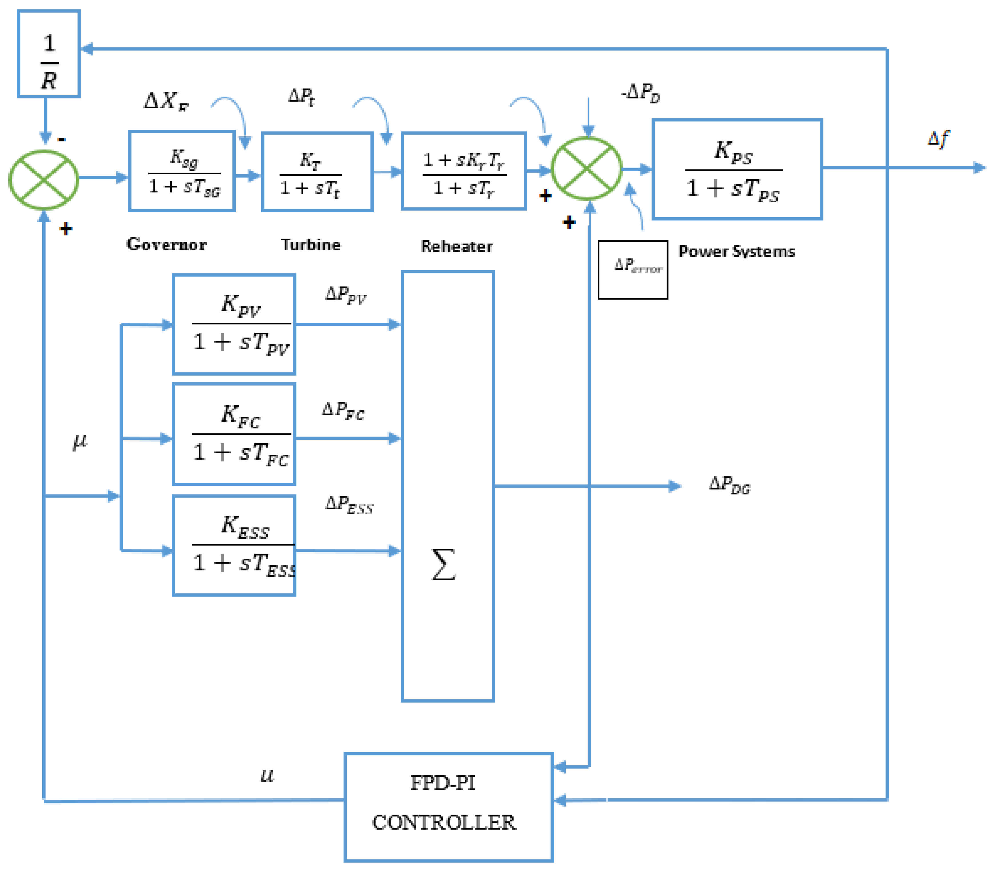
3.1. Hybrid Power System under Study

To control the frequency of HPS, it is important that optimal values be chosen for the FDP-PI controller, and to achieve this, a technique called the GOA is adapted, as shown in Figure 1. A central controller controls all subsystems in the HPS, simplifying the overall system by reducing the number of controllers in response to the electromechanical behavior of the subsystem.

3.2. Mathematical Modelling of the Components:

a. Photovoltaic Cell
The following equation shows the output power of a PV cell:
P PV = η · A · Δ s   [ 1 0.004 ( T a + 25 ) ]
where PV cell efficiency is 8% and is denoted by η , A is the area of the PV array at 4084   m 2 , and s is the change in solar radiation as 1000 kW/m2. A photovoltaic system’s transfer function is given by [41]:
R PV ( s ) = K PV 1 + AT PV = Δ P PV Δ s
b. Fuel Cell
Because of its low pollution and high efficiency, the FC is an essential component of the HPS system. The example of a higher-order system is a FC generator. On the other hand, the first-order transfer function is calculated at a low frequency [41]:
R FC ( s ) = K FC l + AT FC = Δ P FCK Δ P AE
l = 1 ,   2 .
c. Energy Storage System
The control loop, activated by the controller signal, is coupled with energy storage such as ESS. According to the HPS’s requirements for stable operation, the storages mentioned above serve as a source or a load, and their transfer functions are depicted below [41]:
      R ESS ( s ) = K ESS 1 + AT ESS = Δ P ESS Δ U
d. Power Systems
The following equation shows the changing in frequency due to the output [41]:
R ( s ) = Δ f Δ P = 1 D + PS
The damping constant, denoted as D, is set to 0.03, and the inertia constant, denoted as P, is set to 0.4. The rate limits and thresholds are given by |PPV| < 0.08, |PFC| < 0.08, |PESS| < 0.8, and |PPS| < 0.5 [41].

3.3. System Modelling

The block diagram algebra and the grid network for single and multi-source areas are constructed. Figure 1 depict the block diagrams of single area and source (network-1) and single area multi-source (network-2) systems. Network-1 consists of a reheat power system (RPS), while network-2 consists of a hydropower system that works with the RPS. Because of its numerous advantages, the electrical governor is considered in this model [42]. Load disturbance D(s) is followed by the calculation of the transfer faction model of network-1 as shown in (6):
F ( s ) D ( s ) = 4 s 3 + 105.704 s 2 + 273.2 s + 57 s 4 + 34.23 s 3 + 54.04 s 2 66.234 s + 19.25
F(s) in (6) denotes the s-domain area frequency for s ≠ −40107. Network-1’s open-loop poles are s = 174.559 , 0.0122126 0.0703775 j , 0.0122126 + 0.0703775 j ,   local maxima ≈ 3.03443 at s ≈ 0.0217636, and local minima ≈ 2.93967 at s ≈ −0.00928054. As the poles are located on the left side of the s plane, it means that the system is in a steady state. Similarly, as shown in (6), the TF model of network-2 is computed in (7) for s ≠ −2.54801 and s ≠ −0.00222123. The poles of test network-2 are s = 1.979 ,   0.00543691 , 0.0040106 0.0029098 j , 0.0040106 + 0.0029098 j , 0.0012921 − 0.0056386j, 0.0012921 + 0.0056386j, which assures network-2 stability.
F ( s ) D ( s ) = 8 s 6 + 349.167 s 5 + 6.99912 s 4 + 342.285 s 3 + 108.006 s 2 1519.64 s 23.1838 s 7 + 2.55568 s 6 + 1025.01 s 5 + 4.11 s 4 + 40.107 s 3 + 2920.32 s 2 + 66.234 s + 19.25
The HPS comprises a photovoltaic PV, FC, and an ESS. The HPS is permitted to collaborate with a RPS, as depicted in Figure 2. The average operational value of the proposed network is taken from [42]. The proposed model’s closed-loop transfer function (TF) is computed and is represented in (7), and s = 1.979 ,   0.00543691 , 0.0040106 0.0029098 j , 0.0040106 + 0.0029098 j ,   0.0012921 0.0056386 j   ,   0.0012921 0.0056386 j . Because all of the poles of (7) are on the left side of the s-plane, the mathematical model’s stability is preserved.

3.4. Proposed Controller

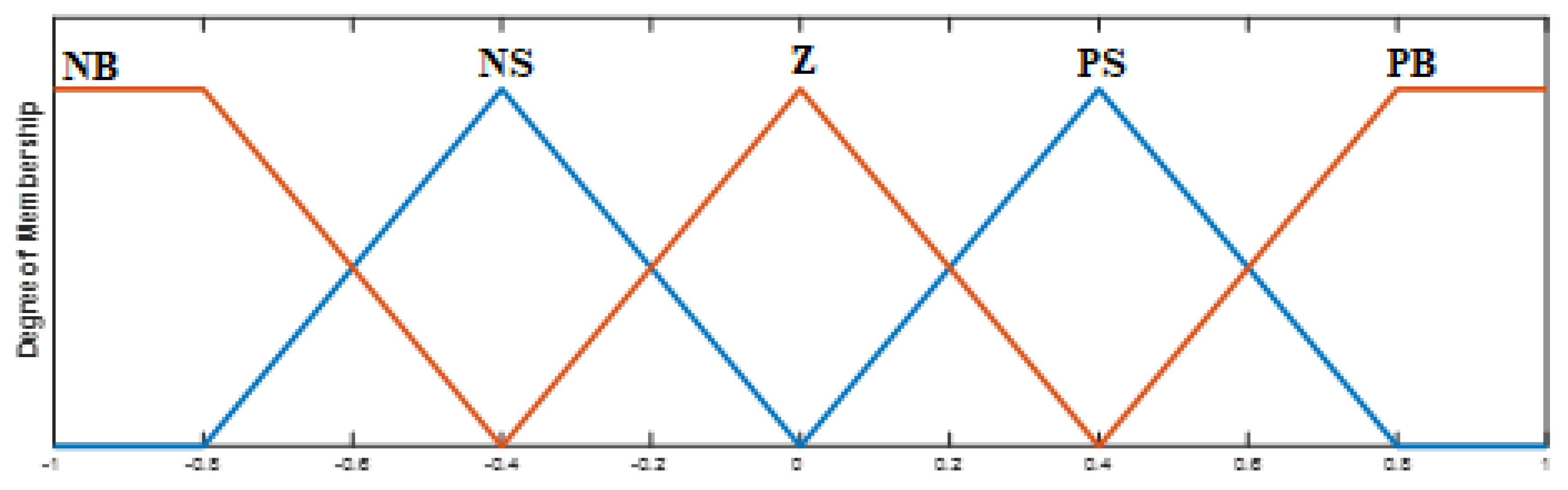
3.4.1. Fuzzy Logic Controller

Compared with traditional controller equivalents, the FLC is a smooth process that generates dependable results even in the presence of system uncertainty and imprecision. When building an FLC, unlike standard control techniques, the necessity of a linearized model may be omitted. Understanding the operating phases of any network to be managed is necessary for constructing the fuzzy rules for the fuzzy logic controller [43]. How well a cascade controller performs depends on the selection of optimal values of the controller for the inner and outer loops. For the inner loop, a PI controller is used as it is faster than the fuzzy controller, while a F-PD controller is used for the outer loop. The difference between the FPD controller’s output signal, R(s), and the signal provided into the PI controller is calculated from the output of the network.
The gains in PID controllers are classified into three types: Kp, Ki, and KD. Similarly, the F-PID and proposed FPD-PI controllers have gains of Kp, Ki, and KD, where the first two are input scaling factors and the latter two are proportional and integral gains. The following are the five triangular membership functions (MF) utilised in the F-PID and FPD-PI controllers. As illustrated in Figure 2, the output and both inputs have a big positive (BP), a small positive (SP), a zero (Z), a small negative (SN), and a big negative (BN), as well as conversion into linguistic value from numeric values using 25 rules. As a result, we employed the identical rule basis as in [43] for the current investigation. In this study, fuzzification is based on a Mamdani-type fuzzy inference system, whereas defuzzification is based on centre of gravity (COG).

3.4.2. Structure of the Fuzzy Logic PD-PI Controller

The classical PID controller is popular among many research communities due to its simple construction and excellent performance at a reasonable cost. However, it does not always function optimally because in order to minimize the steady-state error, the component raised is derivative rather than the integral part, which might lead to unwanted transient behaviour. This problem is alleviated by using the F(PD-PI) controller.
A first-order derivative filter is used in the first stage of the controller to reduce the noise produced by the derivative term. Its transfer function is given below [43]:
Tf FL ( PD PI ) = ( K p + K D ( N s N + S ) ) ( 1 + K pp + K l S )

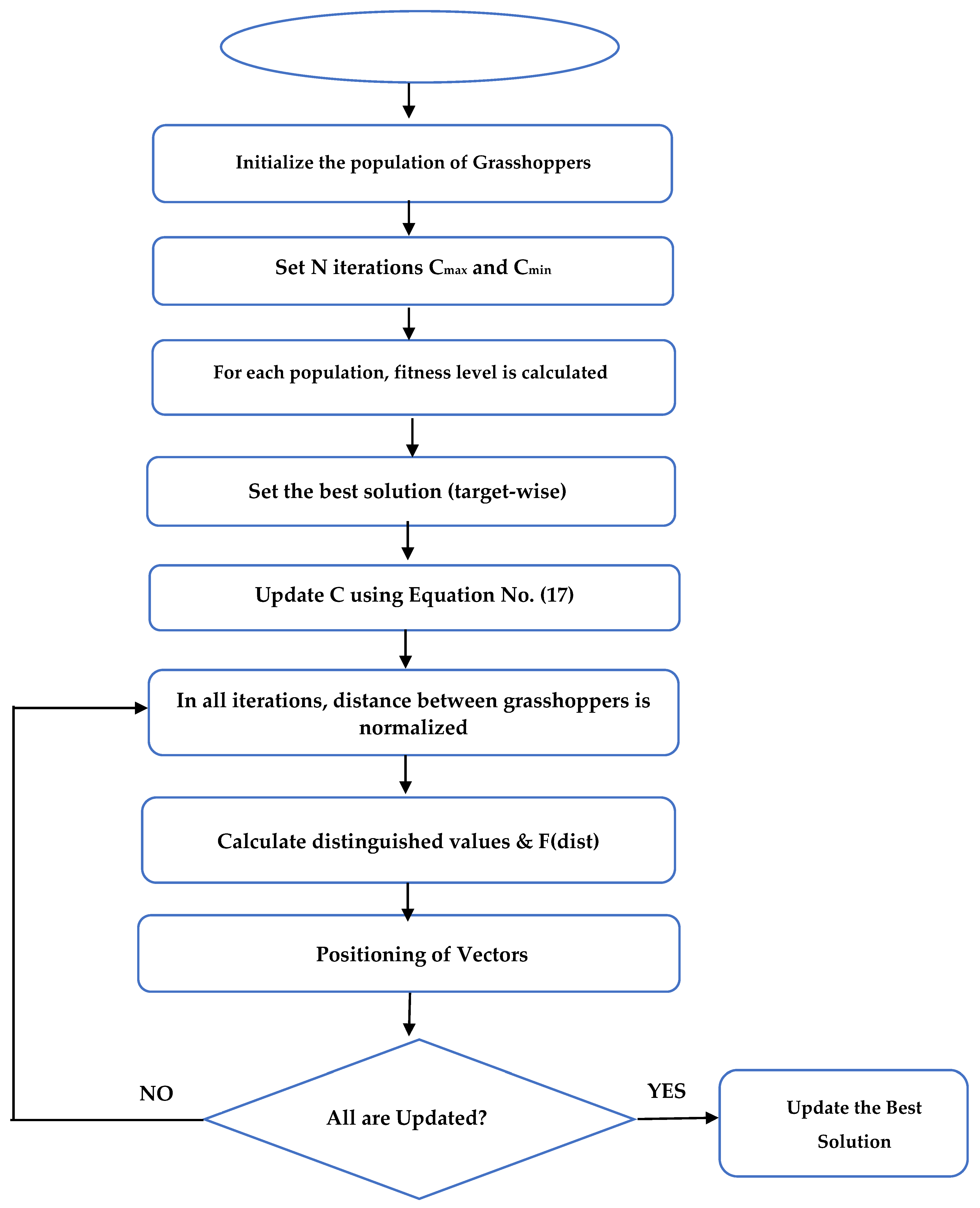
3.5. Optimization Algorithm

The GOA, an optimization algorithm, is proposed and used to solve LFC optimization issues in this paper and obtain the optimized values for the controller [44]. It is a mathematical description of this swarm’s (grasshopper’s) activity in seeking and destroying agricultural items. The algorithm and flowchart are explained below, together with the selection of control parameters and GOA pseudo-codes [45]. The suggested technique mathematically models and duplicates the behaviour of grasshopper swarms in nature to solve optimization challenges.

Grasshopper Optimization Algorithm

Formulation and the description of the variables for the Grasshopper Optimization Algorithm are described in Table 4. Replicating the foraging and swarming characteristics of grasshoppers, Saremi et al. developed a modern and innovative swarm intelligence algorithm called the GOA algorithm. Grasshoppers are well-known nuisance insects that wreak havoc on agricultural productivity and agriculture. Nymph and maturity are the two stages in their life cycle. Little steps and moderate moments are the characteristics of the nymph phase, whereas long-distance and quick moves represent maturity. The actions of larvae and adults illustrate the intensification and diversification phases of the GOA.
The following equation shows the swarming characteristic of grasshoppers [45]:
X i = i = 1 N G i + A i + S I
Equation (1) can be modified as follows to obtain the random grasshopper behaviour:
X i = n 1 S i + n 2 G i + n 3 A i
where n1, n2, and n3 are all random numbers between [0, 1]. The following is how the social interaction Si is defined:
S i = j = 1 j i N S ( | X j X i | ) × X j X i D ij
D ij is a unit vector from ith to jth grasshopper, and s represents the social forces designed by the following equation:
S i ( r ) = fe r l e r
where f and l are the scales of attraction intensity and length. Attraction and repulsion can be used to describe grasshopper social interactions. The gravity force Gi can be calculated using the following equation [45]:
G i = g e ^ g
The following equation gives the wind advection A i [45]:
A i = u e ^ w
where u represents the drift constant and e ^ w is the unity vector towards the direction of the wind. After substituting the values of S, G, and A, the following equation can be obtained:
X i = j = 1 j i N   S ( X j X i ) ( X j X i D ij ) g e ^ g   + u e ^ w
This equation is improved in the following way:
X i d = c ( j = 1 j i N   c ub d lb d 2 s ( X j d X i d ) ) X j X i D ij + T D
where ub d and lb d are upper and lower bounds in the d-th dimension, respectively. T D signifies the best solution discovered so far in the d-th dimension space and c is a decreasing coefficient computed from (17).
c = c max l [ ( c max c min ) L ]
The cmax and cmin are the limits for expressing declining coefficients where the values are 1 and 0.00001 are considered, respectively. l is the recent iteration whereas L denotes a total number of iterations. According to (17), the grasshopper’s future position is decided by its present location, its next target, and the spot of other grasshoppers. In contrast to PSO, GOA incorporates just one position vector to enhance current solutions, accelerating GOA’s convergence mobility. Global best, personal best, and current position determine the current position of a swarm in PSO. However, in GOA, search agents change their position concerning the position of other swarms, their current position, and the global best. Figure 3 depicts the GOA flowchart.
The LFC problem is explored in this article as a disturbance rejection. As this issue is framed in an optimization problem, selecting appropriate performance indexes is necessary. The objective function based on integral time absolute error (ITAE) is preferred for pursuing the optimal gains of the FPD-PI controller using GOA, as explained in (18). The lower the J value, the better the optimum controller settings and the power system’s dynamic characteristics [46].
J = 0 T | Δ f | × t × dt
The range of the optimization problem is the controller gains and is chosen according to [19,46]:
{ K p , min K p K p , max K i , min K i K i , max }

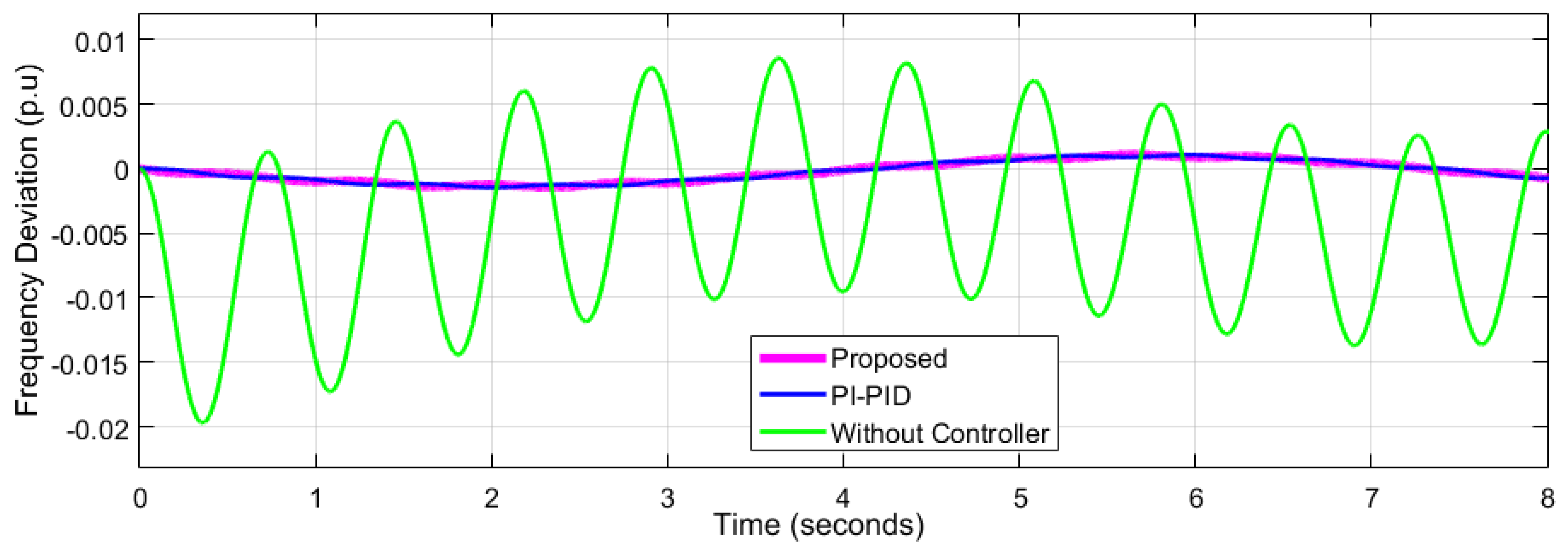
4. Results and Discussion

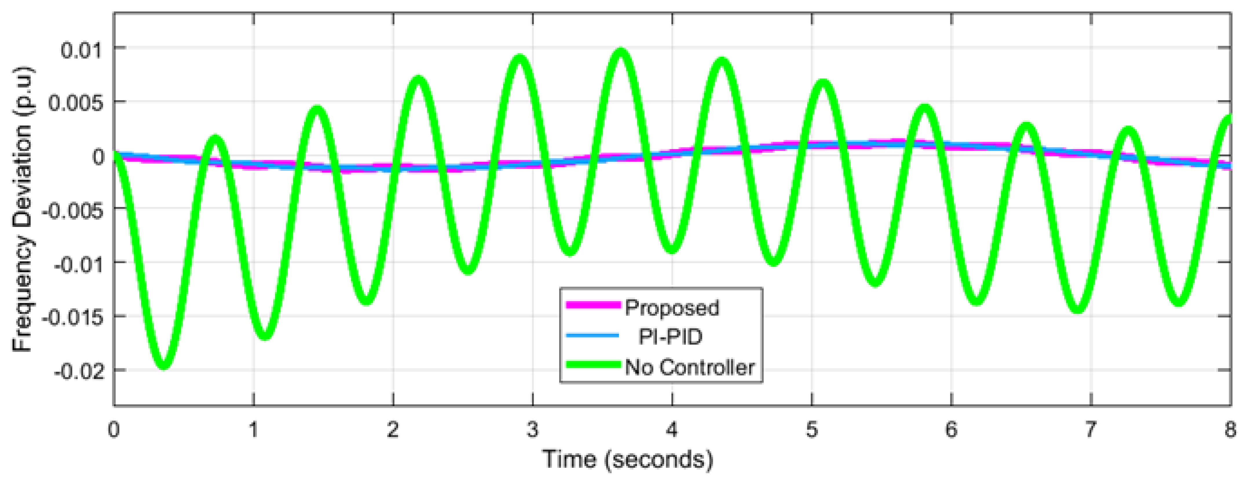
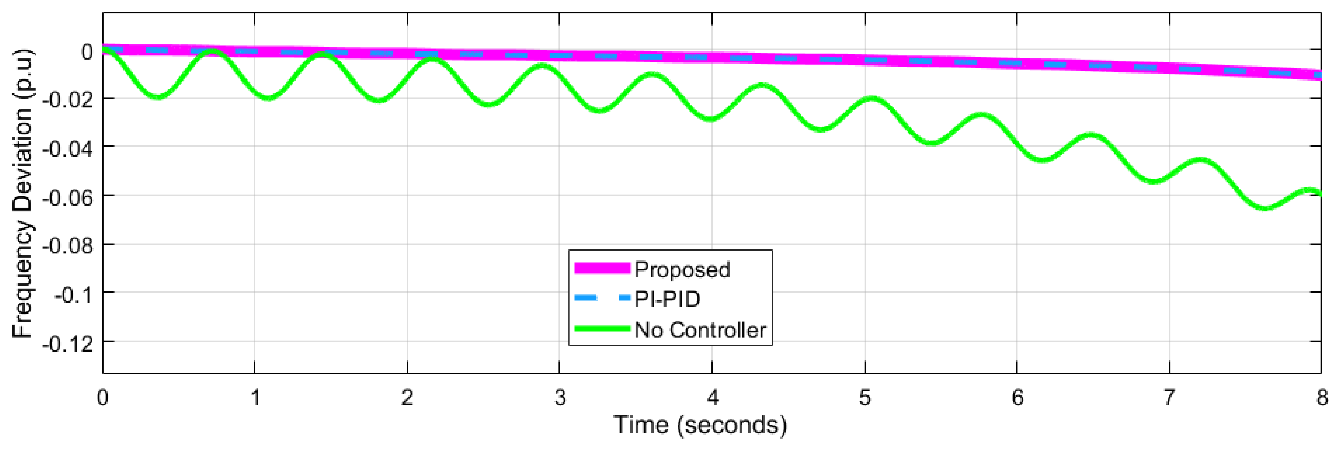
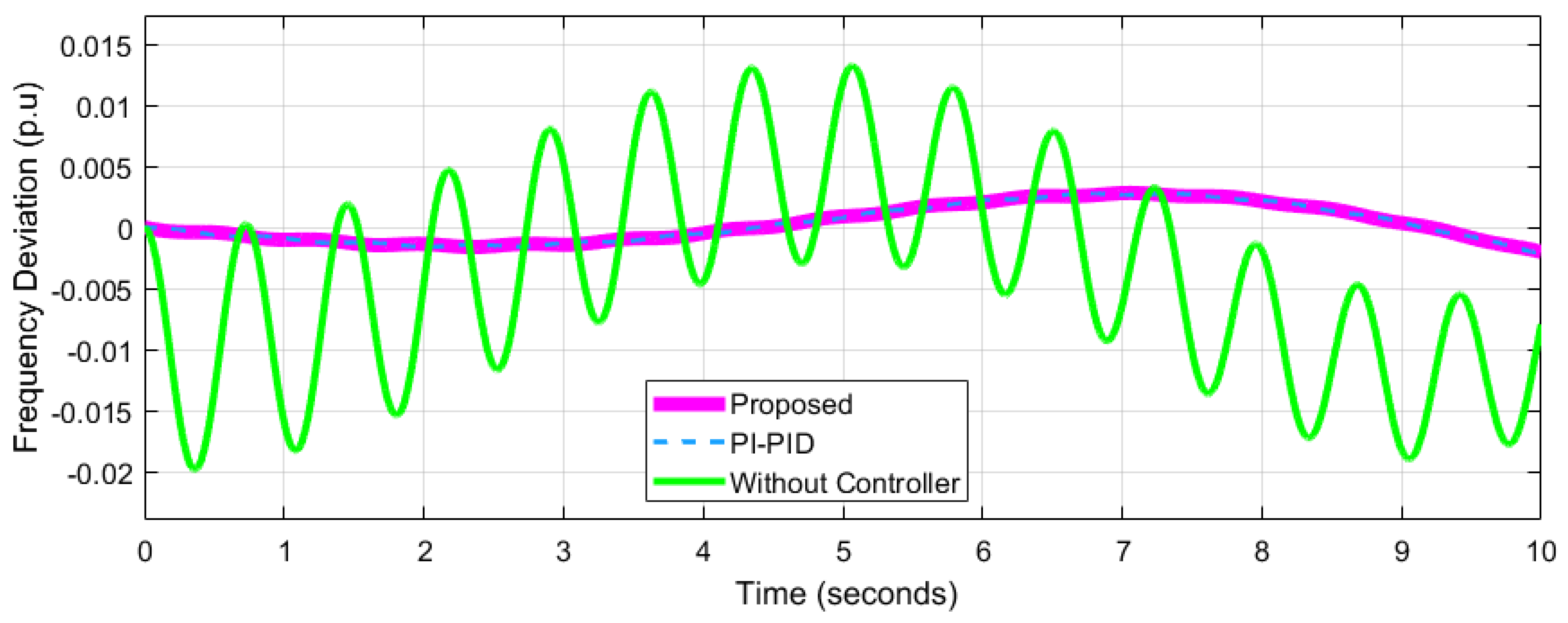
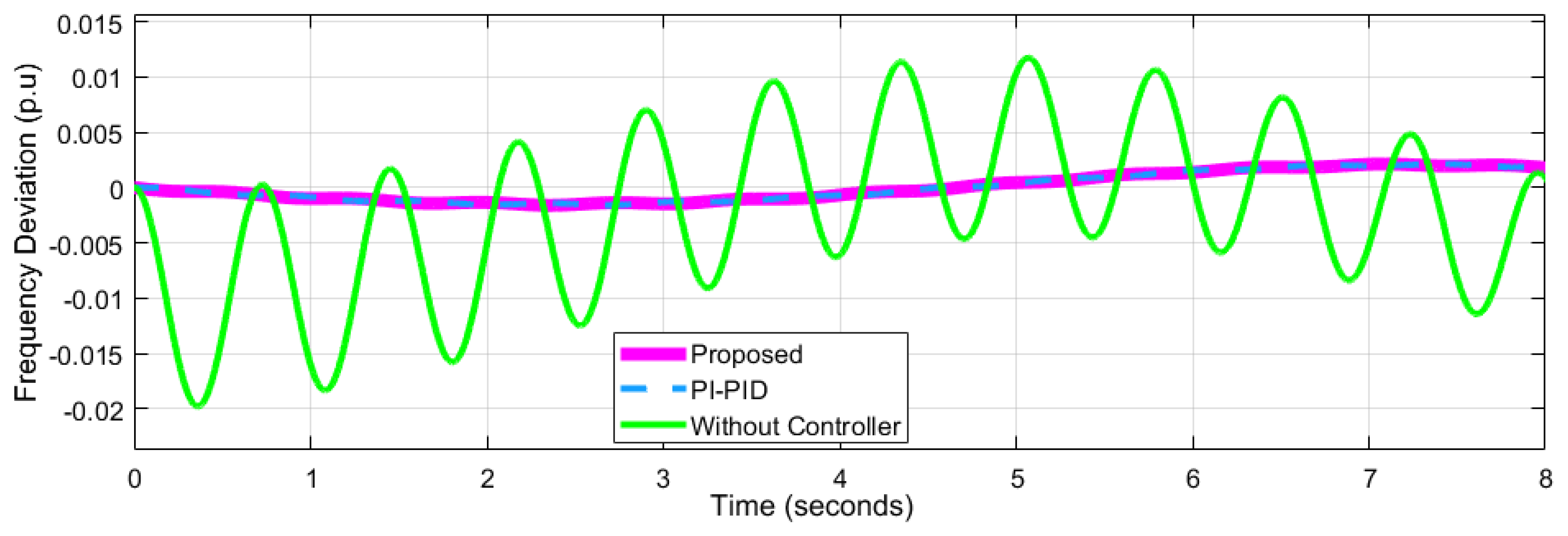
4.1. Performance Analysis for Network 1

The proposed FPD-PI controller is used as a second controller to boost the effective damping of frequency oscillations caused by the load perturbation. Table 5, Table 6 and Table 7 show the controller settings that are optimized with the GOA of network-1, Network-2, and network-3 respectively. The GOA: FPD-PI controller has the shortest settling time, the fewest oscillations, and the highest peak magnitude.

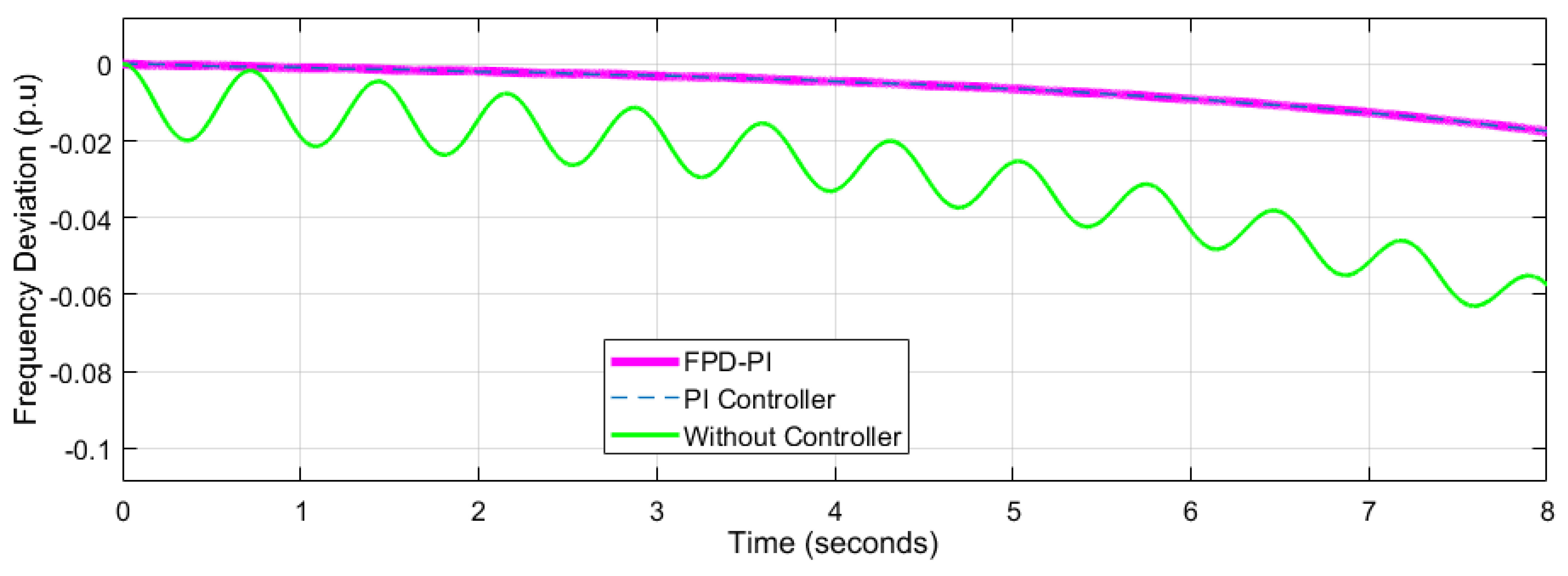
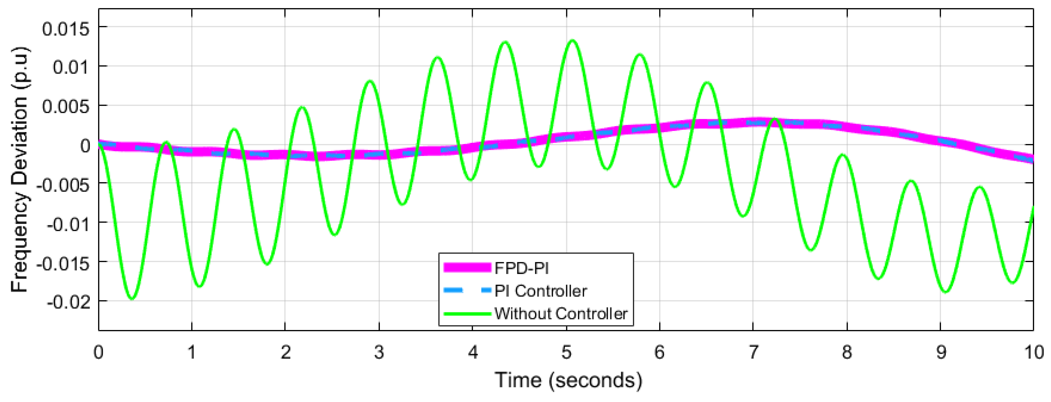
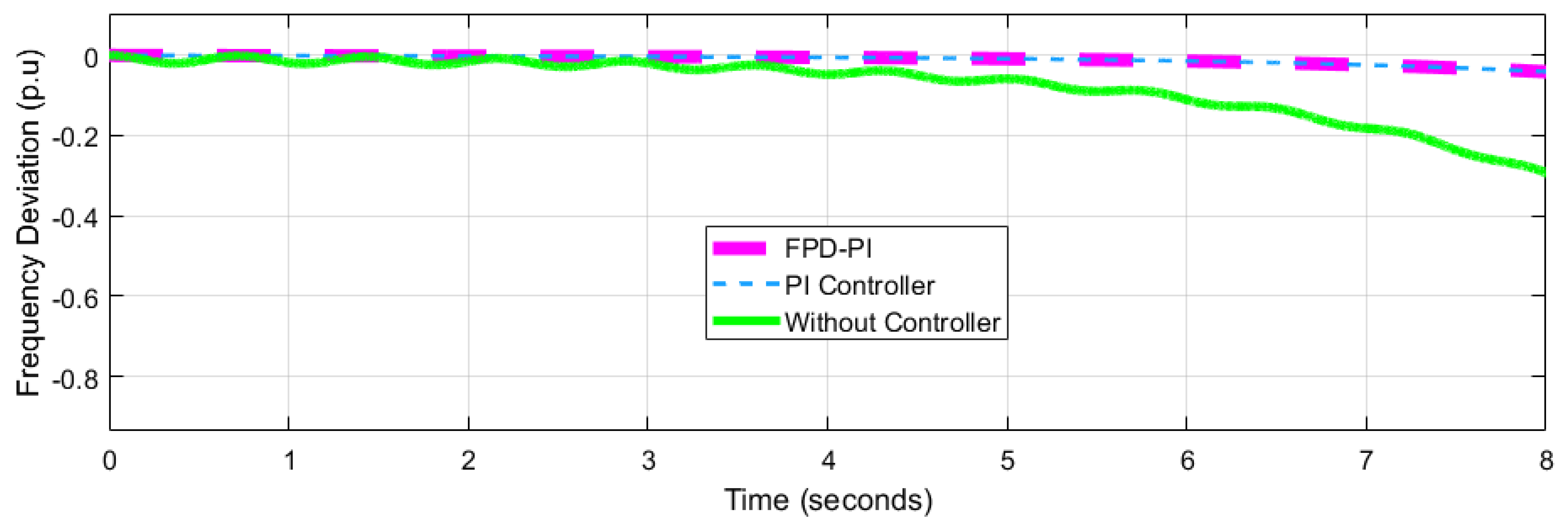
4.2. Performance Analysis of Network 2

The dynamic behaviour of network-2 shown in Figure 1 was used to validate the efficacy of the GOA: FPD-PI controller (b). The suggested GOA: FPD-PI controller, according to the results, is less sensitive to parameter fluctuations and does not need retuning of the gains for parameter disparities. It has also been established that the FPD-PI controller has improved disturbance refutation capacity in both standard and disturbed systems.
In the previous work presented in Table 6, the authors developed different networks of the power system to make the system complex. Figure 4, Figure 5, Figure 6 and Figure 7 are the results of network-1, where it can be observed that there is a huge oscillation in the system when the controller is not used. Similarly, Figure 8, Figure 9 and Figure 10 are the results for network-2, and the same oscillations are observed when the controller is not used. In addition, Figure 10, Figure 11, Figure 12 and Figure 13 are the results for network-3, and the results show that the system we developed can create massive oscillation in the proposed power system. In Table 8, a comparison of results is shown in which it can be observed that the particle swam optimization based on wind power system has fewer oscillations, although it considered the wind power only [47]. This network is not suitable for the complex system as we proposed. Ant colony algorithms are placed on hydrothermal power plants; the networks are complex, and frequency deviation is high compared with our work [48]. In the end, the comparison between bat algorithms and our model shows that the frequency deviation is comparatively low in the proposed system. In fact, we proposed both fuzzy-PID with GOA and PI-PID with GOA, and the results for the proposed controllers (fuzzy-PID with GOA and PI-PID with GOA) are almost the same. In the article, we proposed fuzzy-PID with GOA because this controller gives a low overshoot and shorter settling time than the other ones.

5. Conclusions and Future Studies

An attempt was made to evaluate the efficacy of an FPD-PI controller for LFC hybrid and isolated power systems. For the first time, in order to optimize the gains of FDP-PI controller, an algorithm called the GOA was implemented successfully. The resilience of the developed controller was validated in the face of random load disturbances and large parameter fluctuations. The probability density of frequency deviation verified the GOA: FPD-PI controller’s excellence and resilience. Classical PID controllers may not perform well in LFC, especially when there are non-linearities and stochastic changes in demand, wind, and solar power. The current research presents an FPD-PI controller for the frequency control of hybrid energy sources such as solar, storage devices, and power systems to optimize system performance; the controller is utilized to optimize the FPD-PI parameters for the frequency management of the hybrid system under consideration. For frequency management, the FDP-PI GOA-based controller was found to be more effective than the standard PID controller. This study was conducted to evaluate how the system performs under the influence of varying parameters, and the results are promising as they show that the performance of the system is acceptable even when the parameters change. Finally, because it outperforms other recently suggested frequency control strategies, the frequency-regulated strategy, i.e., GOA-based FPD-PI, is widely recommended and employed in a test procedure.
In the future, this proposed model can be implemented to control frequency deviation in more complex power systems to validate its effectiveness. Moreover, by considering a new variety of power generation like wind or thermal power, the model can be implemented for controlling the frequency deviation. Lastly, we plan to perform a stability analysis to check the stability of our model through various microgrids where load variations are very high.

Author Contributions

Writing—Original draft preparation, methodology, validation, Conceptualization, H.M., M.S., R.M.A., E.T.E.; Conceptualization, data curation, and visualization, A.Y.; formal analysis, investigation, funding acquisition, E.T.E.; project administration, supervision, R.M.A.; Writing—review & editing, methodology, A.U.R.; Investigation, Validation, M.S.; Writing—review & editing, Project administration, H.H.; All authors have read and agreed to the published version of the manuscript.

Funding

This research was supported by the Future University Researchers Supporting Project Number FUESP-2020/48 at Future University in Egypt, New Cairo 11845, Egypt.

Institutional Review Board Statement

Not applicable.

Informed Consent Statement

Not applicable.

Data Availability Statement

Not applicable.

Conflicts of Interest

The authors declare no conflict of interest.

References

  1. Barik, A.K.; Das, D.C. Expeditious frequency control of solar photovoltaic/biogas/biodiesel generator based isolated renewable microgrid using grasshopper optimisation algorithm. IET Renew. Power Gener. 2018, 12, 1659–1667. [Google Scholar] [CrossRef]
  2. Barisal, A.K.; Mishra, S. Improved PSO based automatic generation control of multi-source nonlinear power systems interconnected by AC/DC links. Cogent Eng. 2018, 5, 1422228. [Google Scholar] [CrossRef]
  3. Padhan, S.; Sahu, R.K.; Panda, S. Application of firefly algorithm for load frequency control of multi-area interconnected power system. Electr. Power Compon. Syst. 2014, 42, 1419–1430. [Google Scholar] [CrossRef]
  4. Mostafa Elsaied, M.; Abdallah Attia, M.; Abdelhamed Mostafa, M.; Fouad Mekhamer, S. Application of different optimization techniques to load frequency control with WECS in a multi-area system. Electr. Power Compon. Syst. 2018, 46, 739–756. [Google Scholar] [CrossRef]
  5. Yang, J.; Zeng, Z.; Tang, Y.; Yan, J.; He, H.; Wu, Y. Load frequency control in isolated micro-grids with electrical vehicles based on multivariable generalized predictive theory. Energies 2015, 8, 2145–2164. [Google Scholar] [CrossRef]
  6. Khan, M.I.; Khan, I.A.; Chang, Y.C. An overview of global renewable energy trends and current practices in Pakistan—A perspective of policy implications. J. Renew. Sustain. Energy 2020, 12, 056301. [Google Scholar] [CrossRef]
  7. Goyal, H.; Handmandlu, M.; Kothari, D.P. A novel modelling technique for automatic load frequency control of small hydro power plants. Int. J. Model. Simul. 2007, 27, 186–192. [Google Scholar] [CrossRef]
  8. Pan, I.; Das, S. Fractional-order load-frequency control of interconnected power systems using chaotic multi-objective optimization. Appl. Soft Comput. 2015, 29, 328–344. [Google Scholar] [CrossRef]
  9. Debbarma, S.; Saikia, L.C.; Sinha, N. Automatic generation control using two degree of freedom fractional order PID controller. Int. J. Electr. Power Energy Syst. 2014, 58, 120–129. [Google Scholar] [CrossRef]
  10. Khooban, M.H.; ShaSadeghi, M.; Niknam, T.; Blaabjerg, F. Analysis, control and design of speed control of electric vehicles delayed model: Multi-objective fuzzy fractional-order PIλDμ controller. IET Sci. Meas. Technol. 2017, 11, 249–261. [Google Scholar] [CrossRef]
  11. Gheisarnejad, M.; Khooban, M.H. Design an optimal fuzzy fractional proportional integral derivative controller with derivative filter for load frequency control in power systems. Trans. Inst. Meas. Control 2019, 41, 2563–2581. [Google Scholar] [CrossRef]
  12. Alhelou, H.H.; Hamedani-Golshan, M.E.; Heydarian-Forushani, E.; Al-Sumaiti, A.S.; Siano, P. Decentralized fractional order control scheme for LFC of deregulated nonlinear power systems in presence of EVs and RER. In Proceedings of the IEEE 2018 International Conference on Smart Energy Systems and Technologies (SEST), Seville, Spain, 10–12 September 2018; pp. 1–6. [Google Scholar]
  13. Arya, Y.; Kumar, N. BFOA-scaled fractional order fuzzy PID controller applied to AGC of multi-area multi-source electric power generating systems. Swarm Evol. Comput. 2017, 32, 202–218. [Google Scholar] [CrossRef]
  14. Peddakapu, K.; Mohamed, M.R.; Srinivasarao, P.; Leung, P.K. Frequency stabilization in interconnected power system using bat and harmony search algorithm with coordinated controllers. Appl. Soft Comput. 2021, 113, 107986. [Google Scholar] [CrossRef]
  15. Paliwal, N.; Srivastava, L.; Pandit, M. Application of grey wolf optimization algorithm for load frequency control in multi-source single area power system. Evol. Intell. 2022, 15, 563–584. [Google Scholar] [CrossRef]
  16. Guchhait, P.K.; Banerjee, A. Stability enhancement of wind energy integrated hybrid system with the help of static synchronous compensator and symbiosis organisms search algorithm. Prot. Control. Mod. Power Syst. 2020, 5, 11. [Google Scholar] [CrossRef]
  17. Khamari, D.; Kumbhakar, B.; Patra, S.; Laxmi, D.A.; Panigrahi, S. Load Frequency Control of a Single Area Power System using Firefly Algorithm. Int. J. Eng. Res. 2020, 9, 1318–1320. [Google Scholar]
  18. Amini, M.; Almassalkhi, M. Investigating delays in frequency-dependent load control. In Proceedings of the 2016 IEEE Innovative Smart Grid Technologies-Asia (ISGT-Asia), Melbourne, VIC, Australia, 28 November–1 December 2016; pp. 448–453. [Google Scholar]
  19. Bakar Siddique, M.A.; Asad, A.; Asif, R.M.; Rehman, A.U.; Sadiq, M.T.; Ullah, I. Implementation of Incremental Conductance MPPT Algorithm with Integral Regulator by using Boost Converter in Grid Connected PV Array. IETE J. Res. 2021, 67. [Google Scholar] [CrossRef]
  20. Habib, A.; Sou, C.; Hafeez, H.M.; Arshad, A. Evaluation of the effect of high penetration of renewable energy sources (RES) on system frequency regulation using stochastic risk assessment technique (an approach based on improved cumulant). Renew. Energy 2018, 127, 204–212. [Google Scholar] [CrossRef]
  21. Hernández, J.C.; Sanchez-Sutil, F.; Vidal, P.G.; Rus-Casas, C. Primary frequency control and dynamic grid support for vehicle-to-grid in transmission systems. Int. J. Electr. Power Energy Syst. 2018, 100, 152–166. [Google Scholar] [CrossRef]
  22. Panwar, A.; Sharma, G.; Bansal, R.C. Optimal AGC design for a hybrid power system using hybrid bacteria foraging optimization algorithm. Electr. Power Compon. Syst. 2019, 47, 955–965. [Google Scholar] [CrossRef]
  23. Yousaf, A.; Asif, R.M.; Shakir, M.; Rehman, A.U.; S. Adrees, M. An Improved Residential Electricity Load Forecasting Using a Machine-Learning-Based Feature Selection Approach and a Proposed Integration Strategy. Sustainability 2021, 13, 6199. [Google Scholar] [CrossRef]
  24. Tielens, P.; Van Hertem, D. Grid inertia and frequency control in power systems with high penetration of renewables. In Proceedings of the Young Researchers Symposium in Electrical Power Engineering, Delft, The Netherlands, 16–17 April 2012. [Google Scholar]
  25. Mosca, C.; Bompard, E.; Aluisio, B.; Migliori, M.; Vergine, C.; Cuccia, P. HVDC for frequency stability under RES penetration: The Sardinia island case. In Proceedings of the 2019 AEIT HVDC International Conference (AEIT HVDC), Florence, Italy, 9–10 May 2019; pp. 1–6. [Google Scholar]
  26. Shams, N.; Wall, P.; Terzija, V. Active power imbalance detection, size and location estimation using limited PMU measurements. IEEE Trans. Power Syst. 2018, 34, 1362–1372. [Google Scholar] [CrossRef]
  27. Siddique, M.A.B.; Khan, M.A.; Asad, A.; Rehman, A.U.; Asif, R.M.; Rehman, S.U. Maximum Power Point Tracking with Modified Incremental Conductance Technique in Grid-Connected PV Array. In Proceedings of the 2020 5th International Conference on Innovative Technologies in Intelligent Systems and Industrial Applications (CITISIA), Sydney, Australia, 25–27 November 2020; pp. 1–6. [Google Scholar]
  28. Lu, N. An evaluation of the HVAC load potential for providing load balancing service. IEEE Trans. Smart Grid 2012, 3, 1263–1270. [Google Scholar] [CrossRef]
  29. Dechanupaprittha, S.; Jamroen, C. Self-learning PSO based optimal EVs charging power control strategy for frequency stabilization considering frequency deviation and impact on EV owner. Sustain. Energy Grids Netw. 2021, 26, 100463. [Google Scholar] [CrossRef]
  30. Rebours, Y.G.; Kirschen, D.S.; Trotignon, M.; Rossignol, S. A survey of frequency and voltage control ancillary services—Part I: Technical features. IEEE Trans. Power Syst. 2007, 22, 350–357. [Google Scholar] [CrossRef]
  31. Yousaf, A.; Asif, R.M.; Shakir, M.; Rehman, A.U.; Alassery, F.; Hamam, H.; Cheikhrouhou, O. A Novel Machine Learning-Based Price Forecasting for Energy Management Systems. Sustainability 2021, 13, 12693. [Google Scholar] [CrossRef]
  32. Saxena, S.; Hote, Y.V. Load frequency control in power systems via internal model control scheme and model-order reduction. IEEE Trans. Power Syst. 2013, 28, 2749–2757. [Google Scholar] [CrossRef]
  33. Shiva, C.K.; Mukherjee, V. A novel quasi-oppositional harmony search algorithm for AGC optimization of three-area multi-unit power system after deregulation. Eng. Sci. Technol. Int. J. 2016, 19, 395–420. [Google Scholar] [CrossRef]
  34. Masood, B.; Khan, M.A.; Baig, S.; Song, G.; Rehman, A.U.; Rehman, S.U.; Rasheed, M.B. Investigation of deterministic, statistical and parametric NB-PLC channel modeling techniques for advanced metering infrastructure. Energies 2020, 13, 3098. [Google Scholar] [CrossRef]
  35. Rahman, A.; Saikia, L.C.; Sinha, N. Automatic generation control of an interconnected two-area hybrid thermal system considering dish-stirling solar thermal and wind turbine system. Renew. Energy 2017, 105, 41–54. [Google Scholar] [CrossRef]
  36. Asif, R.M.; Ur Rehman, A.; Ur Rehman, S.; Arshad, J.; Hamid, J.; Tariq Sadiq, M.; Tahir, S. Design and analysis of robust fuzzy logic maximum power point tracking based isolated photovoltaic energy system. Eng. Rep. 2020, 2, e12234. [Google Scholar] [CrossRef]
  37. Prakash, S.; Sinha, S.K. Simulation based neuro-fuzzy hybrid intelligent PI control approach in four-area load frequency control of interconnected power system. Appl. Soft Comput. 2014, 23, 152–164. [Google Scholar] [CrossRef]
  38. Satapathy, P.; Dhar, S.; Dash, P.K. Stability improvement of PV-BESS diesel generator-based microgrid with a new modified harmony search-based hybrid firefly algorithm. IET Renew. Power Gener. 2017, 11, 566–577. [Google Scholar] [CrossRef]
  39. Khooban, M.H.; Niknam, T.; Blaabjerg, F.; Dragičević, T. A new load frequency control strategy for micro-grids with considering electrical vehicles. Electr. Power Syst. Res. 2017, 143, 585–598. [Google Scholar] [CrossRef]
  40. Ullah, A.; Nawi, N.M.; Khan, M.H. BAT algorithm used for load balancing purpose in cloud computing: An overview. Int. J. High Perform. Comput. Netw. 2020, 16, 43–54. [Google Scholar] [CrossRef]
  41. Meinhardt, M.; Cramer, G. Past, present and future of grid connected photovoltaic-and hybrid-power-systems. In Proceedings of the IEEE 2000 Power Engineering Society Summer Meeting (Cat. No. 00CH37134), Seattle, WA, USA, 16–20 July 2000; Volume 2, pp. 1283–1288. [Google Scholar]
  42. Khamari, D.; Sahu, R.K.; Panda, S. Adaptive differential evolution based PDF plus (1+ PI) controller for frequency regulation of the distributed power generation system with electric vehicle. Int. J. Ambient Energy 2022, 43, 3040–3054. [Google Scholar] [CrossRef]
  43. Guha, D.; Roy, P.K.; Banerjee, S. Grasshopper optimization algorithm scaled fractional order PI-D controller applied to reduced order model of load frequency control system. Int. J. Model. Simul. 2020, 40, 217–242. [Google Scholar] [CrossRef]
  44. Tripathy, D.; Behera, S.; Dev Choudhury, N.B. Implementation of Grasshopper optimization algorithm based cascaded fuzzy PD-PI controller for frequency stability in a multi-area power system. J. Interdiscip. Math. 2020, 23, 335–345. [Google Scholar] [CrossRef]
  45. Antoniou, A.; Lu, W.S. Practical Optimization: Algorithms and Engineering Applications; Springer: New York, NY, USA, 2007; Volume 19, p. 669. [Google Scholar]
  46. Saremi, S.; Mirjalili, S.; Lewis, A. Grasshopper optimisation algorithm: Theory and application. Adv. Eng. Softw. 2017, 105, 30–47. [Google Scholar] [CrossRef]
  47. Omar, M.; Soliman, M.; Ghany, A.M.A.; Bendary, F. Optimal tuning of PID controllers for hydrothermal load frequency control using ant colony optimization. Int. J. Electr. Eng. Inform. 2013, 5, 348. [Google Scholar] [CrossRef]
  48. Abd-Elazim, S.M.; Ali, E.S. Load frequency controller design via BAT algorithm for nonlinear interconnected power system. Int. J. Electr. Power Energy Syst. 2016, 77, 166–177. [Google Scholar] [CrossRef]
  49. Kouba, N.E.L.Y.; Menaa, M.; Hasni, M.; Boudour, M. Optimal control of frequency and voltage variations using PID controller based on particle swarm optimization. In Proceedings of the 2015 4th International Conference on Systems and Control (ICSC), Sousse, Tunisia, 28–30 April 2015; pp. 424–429. [Google Scholar]
Figure 1. Transfer function model of the HPS understudy.
Energies 15 06981 g001
Figure 2. Triangular Memebership Function for FLC.
Energies 15 06981 g002
Figure 3. The flowchart of the grasshopper optimization algorithm.
Energies 15 06981 g003
Figure 4. Case 1: frequency deviation at (Kp = −1.6066, Ki = −0.0024) for network 1.
Energies 15 06981 g004
Figure 5. Case 2: frequency deviation at (Kp = −1.9600, Ki = −0.0024) for network 1.
Energies 15 06981 g005
Figure 6. Case 3: frequency deviation at (Kp = −1.7251, Ki = −0.0012) for network 1.
Energies 15 06981 g006
Figure 7. Case 4: frequency deviation at (Kp = −1.881, Ki = −0.0014) for network 1.
Energies 15 06981 g007
Figure 8. Case 1: frequency deviation at (Kp = −1.9185, Ki = −0.0030) for network 2.
Energies 15 06981 g008
Figure 9. Case 2: frequency deviation at (Kp = −1.8703, Ki = −0.0051) for network 2.
Energies 15 06981 g009
Figure 10. Case 3: frequency deviation at (Kp = −1.8196,Ki = −0.0009) for network 2.
Energies 15 06981 g010
Figure 11. Case 1: frequency deviation at (Kp = −1.9111, Ki = −0.0080) for network 3.
Energies 15 06981 g011
Figure 12. Case 2: frequency deviation at (Kp = −1.8700, Ki = −0.0040) for network 3.
Energies 15 06981 g012
Figure 13. Case 3: frequency deviation at (Kp = −1.8914, Ki = −0.0007) for network 3.
Energies 15 06981 g013
Table 1. Time Frames to Regulate Frequency in a Traditional Grid.
Control MechanismTime SlotsAuxiliary Services
Primary Control10–60 sFrequency Response
Secondary Control1–10 minRegulation
Tertiary Control10 min–few hoursImbalance/Reserve
Table 2. Symbolic Representations of the Mathematical Modeling of System Components.
SymbolsDescription
P PV The output power of PV cell
η The efficiency of PV cells, i.e., 8%
A Area of PV array
Δ s Change in solar irradiation
T a Temperature
R PV ( s ) Transfer function (T.F) of PV cell in s-domain
R FC ( s ) The T.F of fuel cell in s-domain
K FC Gain of fuel cell
T FC A constant of time for fuel cell
lNumber of units
R ESS The T.F of ESS
K ESS Gain of energy storage system
T ESS A constant of time for ESS
UIncremental action of the proposed controller
R(s)Transfer function of power system
Δ f Frequency deviation
Δ P Power dynamics in response to oscillations
D Damping constant
PsInertia constant
D(s)Load disturbance
F(s)s-domain area frequency
T · F FL ( PD PI ) Transfer function of fuzzy logic (PD-PI) controller
K p , K D , K i Proportional, integral & derivative gain of the proposed controller
Table 4. Grasshopper Optimization Algorithm.
ComponentsFormulationsDescription of Variable
Grasshopper swarming Behaviour X i = n 1 S i + n 2 G i + n 3 A i Random swarming behaviour of grasshoppers: where X i shows the i-th grasshopper location, the social interaction of grasshoppers is denoted by Si, the gravity force on i-th grasshopper is depicted by Gi, and the wind advection is denoted by Ai.
Social interaction of grasshoppers S i = j = 1 j i N S ( | X j X i | ) × X j X i D ij Number of grasshoppers is shown by N, and the displacement between i-th and j-th grasshopper is denoted by D ij
Social forces of grasshopper S i ( r ) = fe r l e r The force of attraction is taken as: [2.079,4], while repulsion is taken as. [0,2.079]. Note that no force should be precisely at 2.079. This is referred a ’comfort zone.’
The component of gravity G i = g e ^ g The G i . is a gravitational constant referring to the centre of earth, i.e., e ^ g
The advection of wind A i = u e ^ w u is the ‘drift constant’ and e ^ w is a unity vector following the direction of the wind. A baby grasshopper has no wings, so its movements are highly dependent upon the wind.
The substituted equation for swarming behaviour of grasshoppers X i = j = 1 j i N   S ( X j X i ) ( X j X i D ij )   g e ^ g + u e ^ w In the next step, S, G, and A are all replaced by the defined equations.
Improved calculation of Equation (15) X i d = c ( j = 1 j i N   c ub d lb d 2 s ( X j d X i d ) ) X j X i D ij + T D The issues like reaching of grasshoppers to comfort zone quickly and the non-convergent behaviour of swarm system to the target location does not permit   X i to directly solve the problem of optimization. This is why   X i is transformed into X i d
The decreasing coefficients c = c max l   [ ( c max c min ) L ] The comfort zone is reduced by the coefficient c, which is proportional to the number of iterations
Table 5. Optimized GOA result for controller gains of network 1. [ K A = 0.8180, KB = 0.1121 & Kpp = 0.67].
No. of TrialsProportional Gain
Kp
Derivative Gain
KD
Integral Gain
Ki
1.−1.6066−1.0150−0.0024
2.−1.9600−1.7808−0.0011
3.−1.7251−0.4057−0.0012
4.−1.8811−1.9678−0.0014
Table 6. Optimized GOA result for controller gains of network 2. [ K A = 0.0861, KB = 0.4473 & Kpp = 0.061].
No. of TrialsProportional Gain
Kp
Derivative Gain
KD
Integral Gain
Ki
1.−1.9185−1.7166−0.0030
2−1.8703−1.7753−0.0051
3−1.8196−0.6802−0.0009
Table 7. Optimized GOA result for controller gains network 3. [KA = 0.1072, KB = 0.0143, Kpp = 0.051].
No. of TrialsProportional Gain
Kp
Derivative Gain
KD
Integral Gain
Ki
1−1.9111−1.6176−0.0080
2−1.8700−1.8783−0.0040
3−1.8914−0.5002−0.0007
Table 8. Comparison of Proposed Algorithms with PSO, Ant Colony, and Bat Alogorithms.
No. of IterationParticle Swam Optimization
On Wind Power Based Power System
[49]
Ant Colony Algorithms
On Hydrothermal Power Plant
[47]
Bat Algorithms
For Nonlinear Interconnected
Power Systems
[48]
Proposed
KpKDKiKpKDKiKpKDKiKpKDKi
Network-3.12052.46412.78210.90.980.980.1520.1640.1241.88111.96780.0014
Network-23.12052.46412.78210.40.880.150.1520.1640.124−1.8196−0.6802−0.0009
Network-3------------------0.560.270.210.1520.1640.124−1.8914−0.5002−0.0007
Frequency Deviation
p.u
Network-1 = 0.04547
Network-2= 0.007218
----------------------
Network-1 = 0.06
Network-2 = 0.03
Network-3 = 0.02
Network-1 = 0.05
Network-2 = 0.025
Network-3 = 0.20
Network-1= 0.08
Network-2= 0.02
Network-3= 0.02
Publisher’s Note: MDPI stays neutral with regard to jurisdictional claims in published maps and institutional affiliations.

