
Design Aspects and Performance Evaluation of Pole-Phase Changing Induction Machines

Abstract
:1. Introduction
2. Working Principles of Pole-Phase Changing Induction Machines
2.1. Multiphase Stator Winding Excitation
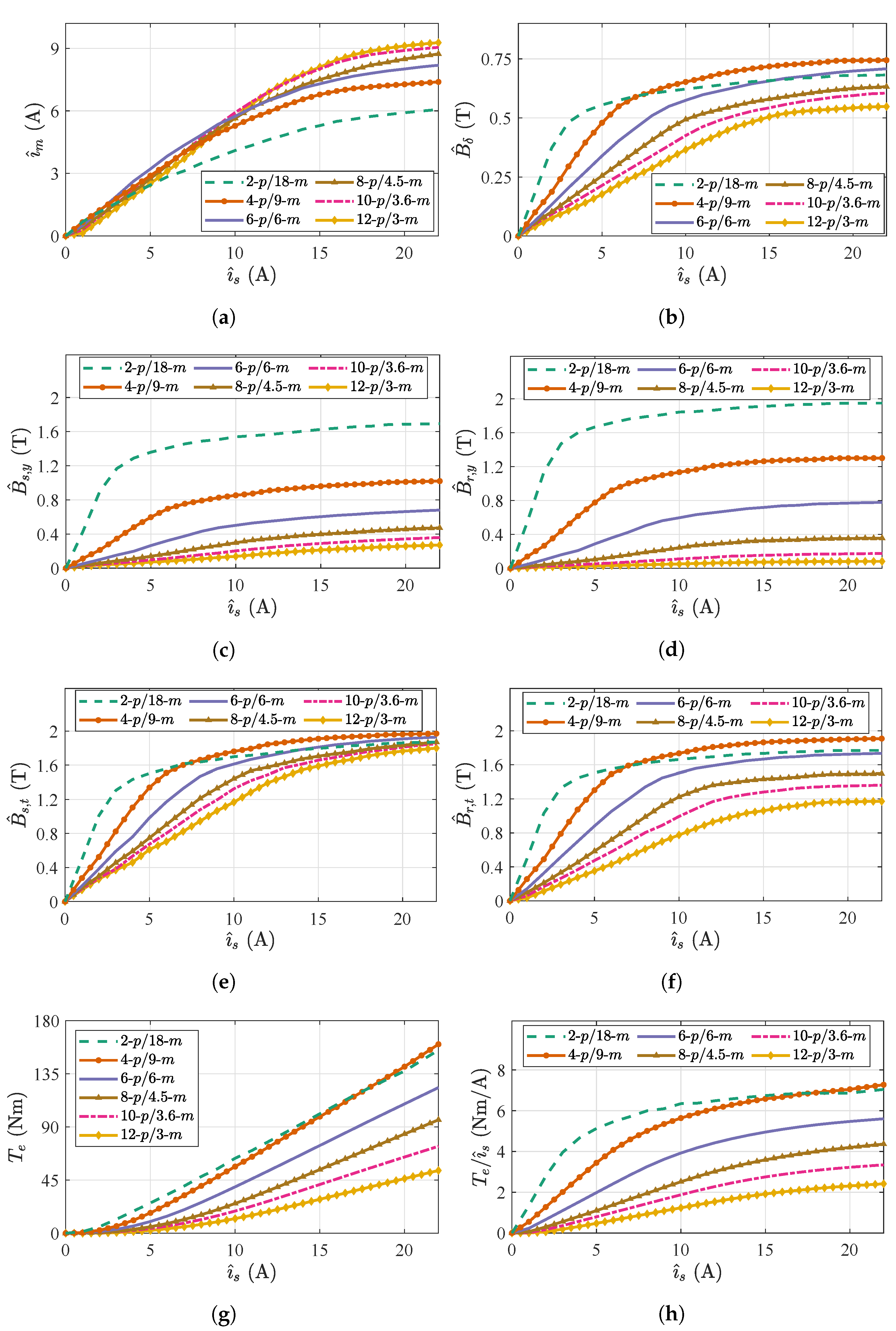
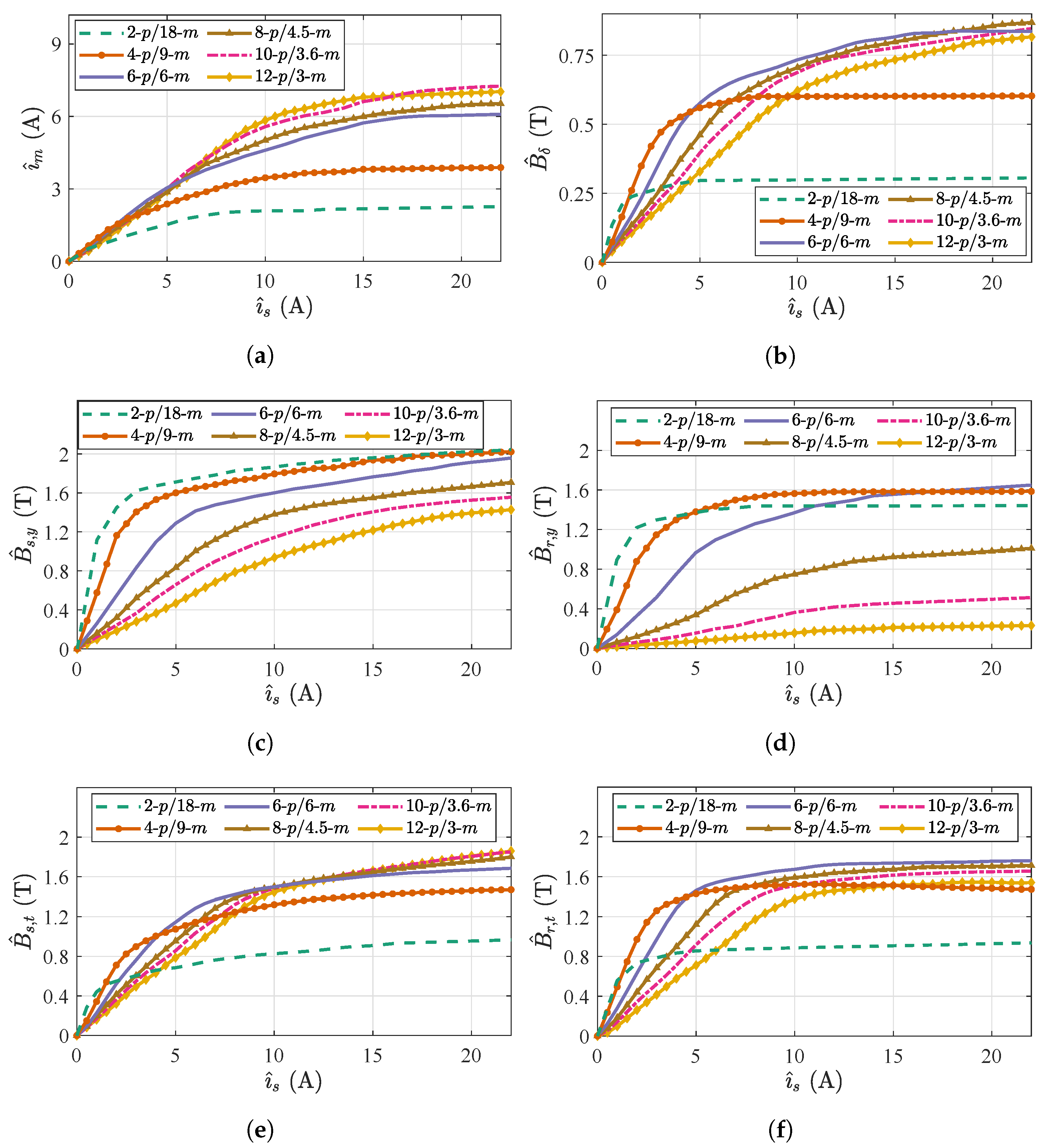
2.2. Torque Capability in Linear and Saturation Region
3. Optimal Pole-Phase Selection Process
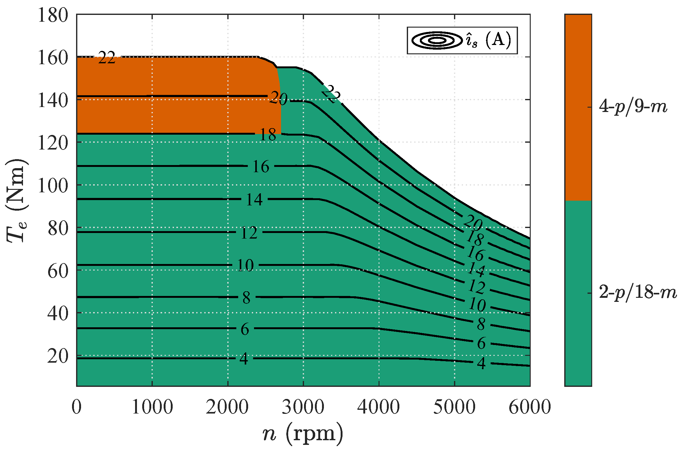
3.1. Maximum Torque Per Ampere Operation
3.1.1. Maximum Torque Per Ampere (MTPA) Control
3.1.2. Flux Weakening (FW) Control
3.1.3. Maximum Torque Per Volt (MTPV) Control
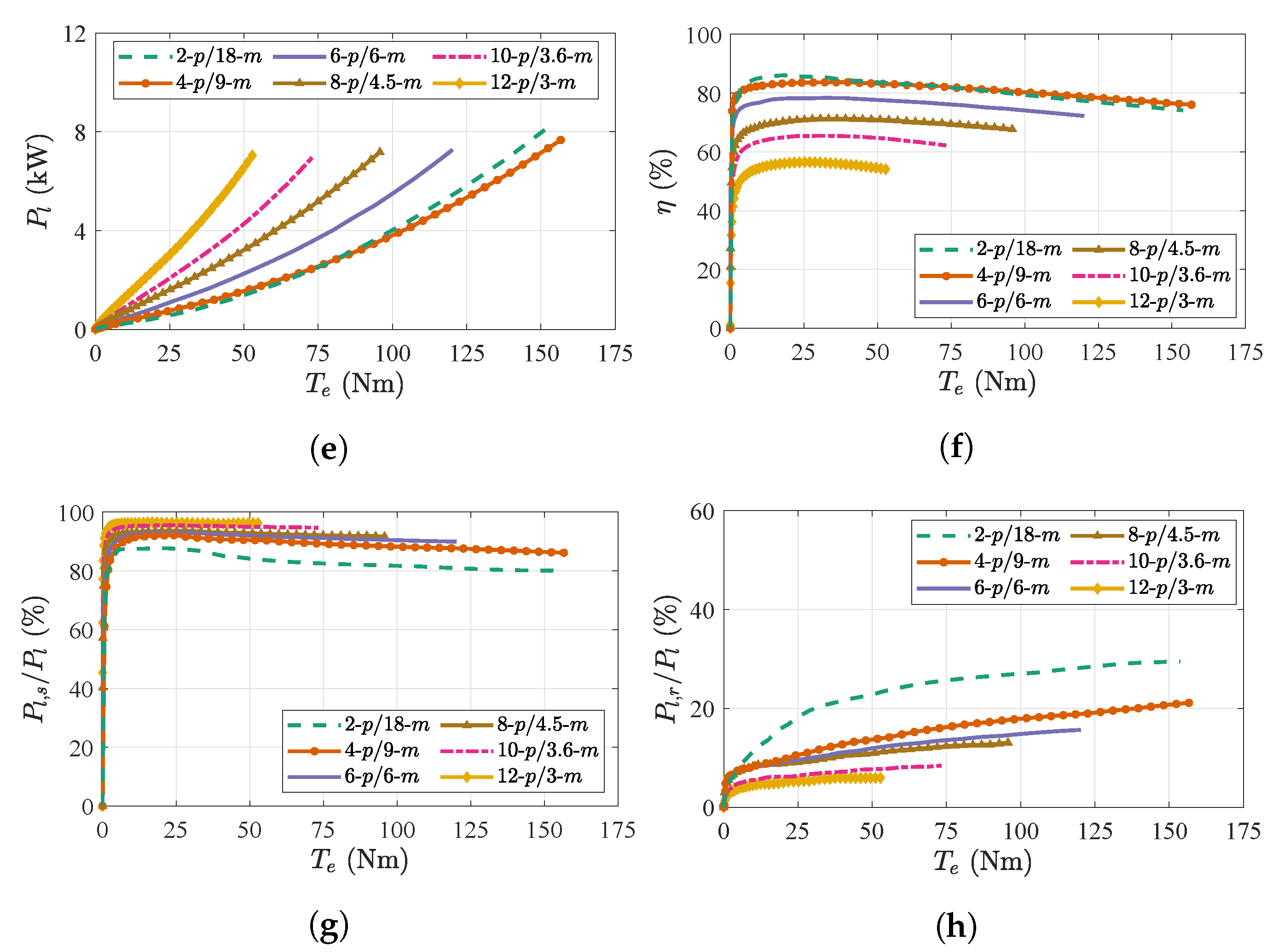
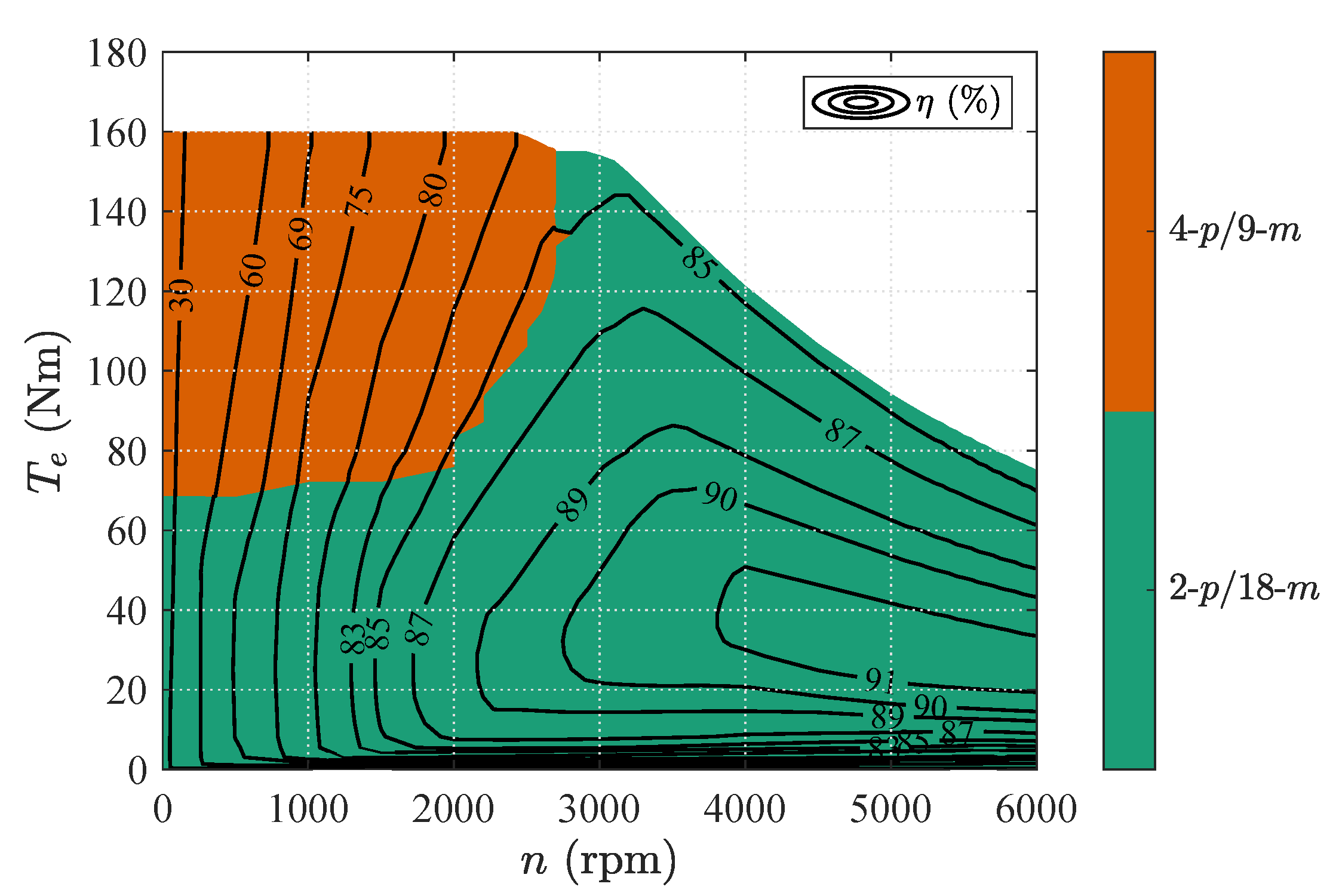
3.2. Maximum Efficiency Operation
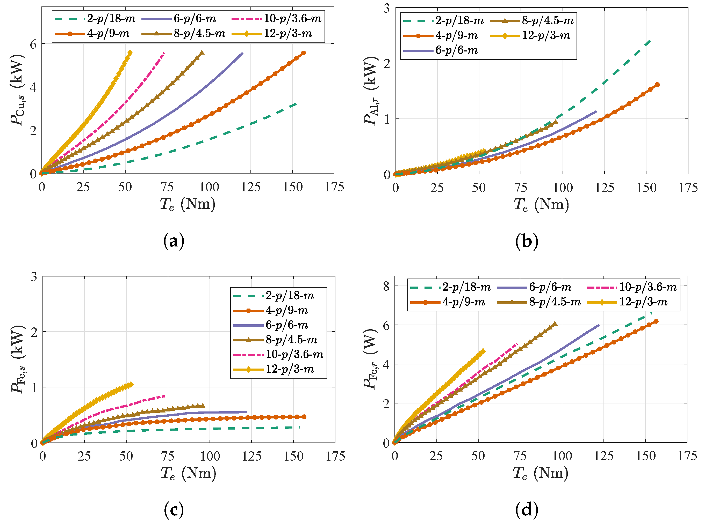
3.2.1. Resistive Losses
3.2.2. Iron Losses
3.2.3. Windage Losses
4. Design Considerations
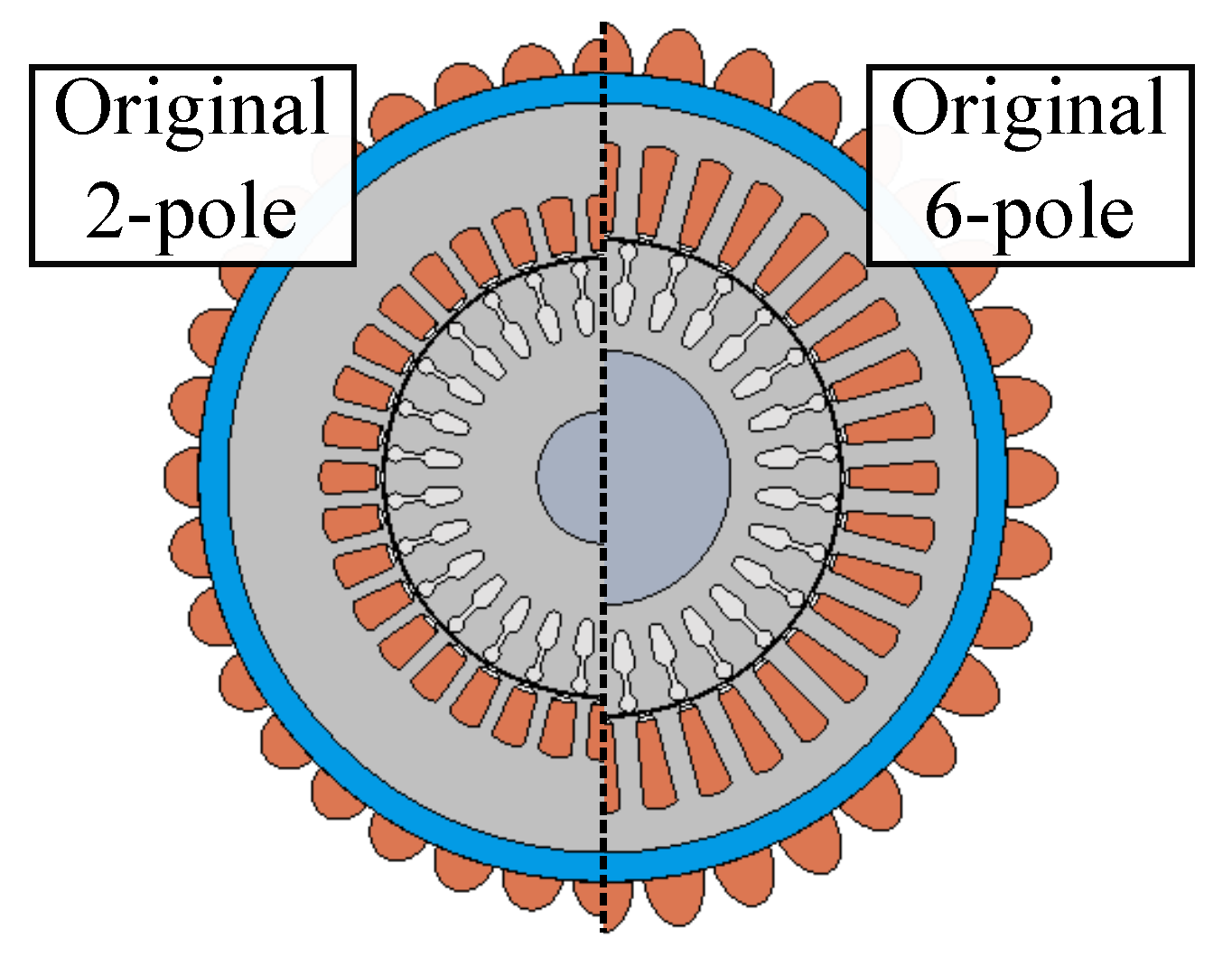
4.1. WICSC Machine Designed for 2-Pole Nominal Operation
4.1.1. Maximum Torque Per Ampere Operation
4.1.2. Maximum Efficiency Operation
4.2. WICSC Machine Designed for 6-Pole Nominal Operation
4.2.1. Maximum Torque Per Ampere Operation
4.2.2. Maximum Efficiency Operation
5. Discussion
6. Conclusions
Author Contributions
Funding
Data Availability Statement
Conflicts of Interest
Abbreviations and Nomenclature
Abbreviations
| FEM | Finite element method |
| FW | Flux weakening |
| IM | Induction machine |
| MTPA | Maximum torque per ampere |
| MTPV | Maximum torque per volt |
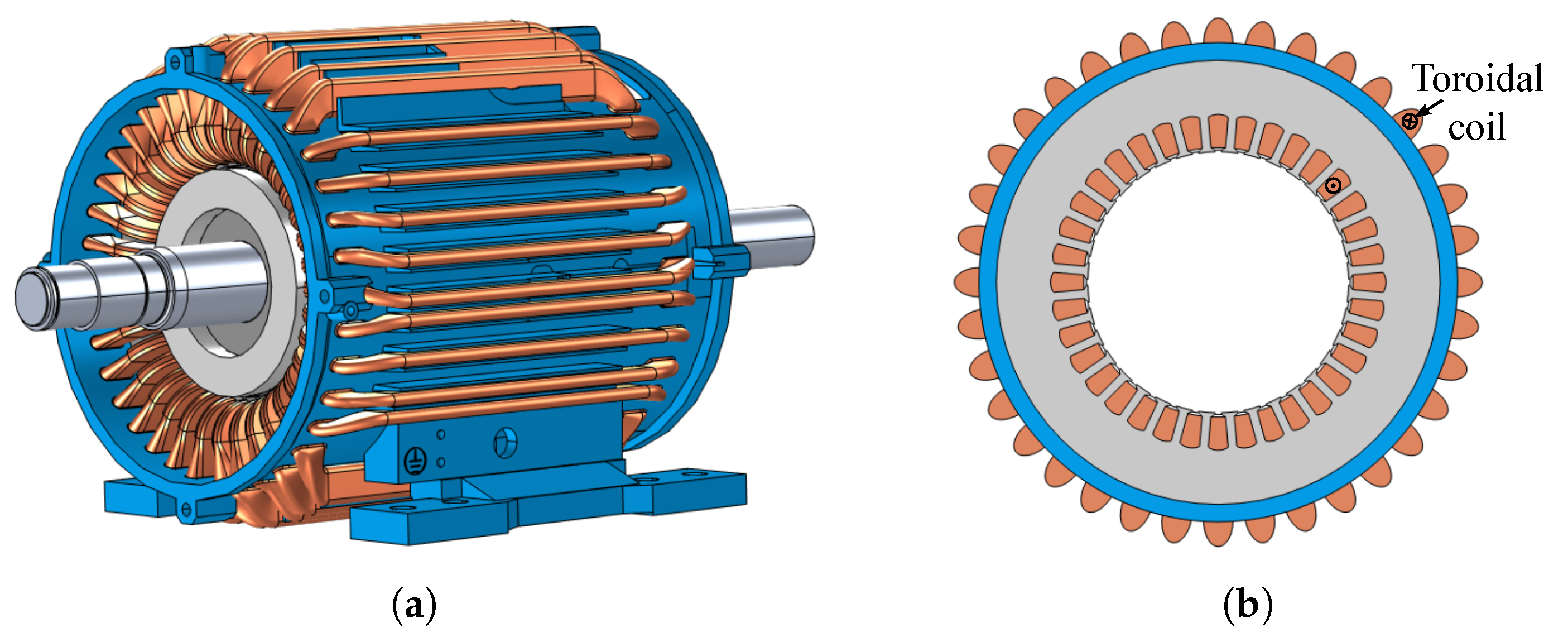
| WICSC | Wound independently-controlled stator coils |
Nomenclature
| Air-gap magnetic flux density | (T) | |
| Skin friction coefficient | (-) | |
| Magnetizing current | (A) | |
| d-axis stator current | (A) | |
| q-axis stator current | (A) | |
| Stator current | (A) | |
| Rotor-bar current amplitude | (A) | |
| Fundamental winding factor | (-) | |
| Eddy-current loss coefficient | (-) | |
| Hysteresis loss coefficient | (-) | |
| Active axial length | (m) | |
| Magnetizing inductance | (H) | |
| m | Number of phases | (-) |
| Number of turns per stator slot | (-) | |
| p | Number of poles | (-) |
| Losses of aluminum squirrel-cage rotor | (W) | |
| Stator copper losses | (W) | |
| Total iron losses | (W) | |
| Stator iron losses | (W) | |
| Rotor iron losses | (W) | |
| Mechanical power | (W) | |
| Windage losses | (W) | |
| Number of stator slots per pole per phase | (-) | |
| Number of stator slots | (-) | |
| Number of rotor bars | (-) | |
| Rotor-bar resistance | () | |
| Re | Reynolds number | (-) |
| Resistance of one short-circuit ring element | () | |
| Resistance of stator-slot coil | () | |
| Rotor radius | (m) | |
| Equivalent rotor-bar resistance | () | |
| Rotor resistance referred to the stator side | () | |
| s | Slip | (-) |
| t | Time | (s) |
| Electromagnetic torque | (Nm) | |
| Stator maximum voltage | (V) | |
| Air-gap length | (m) | |
| Area of the mesh element | (m2) | |
| Efficiency | (-) | |
| d-axis stator flux linkage | (Vs) | |
| Kinematic viscosity of air | (m2/s) | |
| Vacuum permeability | (H/m) | |
| Rotor surface speed | (m/s) | |
| Air density | (kg/m3) | |
| Angular mechanical frequency | (rad/s) | |
| Angular electrical frequency | (rad/s) | |
| Angular slip frequency | (rad/s) |
References
- Men, X.; Guo, Y.; Wu, G.; Chen, S.; Shi, C. Implementation of an Improved Motor Control for Electric Vehicles. Energies 2022, 15, 4833. [Google Scholar] [CrossRef]
- Verbruggen, F.J.R.; Silvas, E.; Hofman, T. Electric Powertrain Topology Analysis and Design for Heavy-Duty Trucks. Energies 2020, 13, 2434. [Google Scholar] [CrossRef]
- Bitsi, K.; Wallmark, O.; Bosga, S. Many-objective Optimization of IPM and Induction Motors for Automotive Application. In Proceedings of the 21st European Conference on Power Electronics and Applications (EPE’19 ECCE Europe), Genova, Italy, 3–5 September 2019; pp. P.1–P.10. [Google Scholar] [CrossRef]
- Wolff, S.; Kalt, S.; Bstieler, M.; Lienkamp, M. Influence of Powertrain Topology and Electric Machine Design on Efficiency of Battery Electric Trucks—A Simulative Case-Study. Energies 2021, 14, 328. [Google Scholar] [CrossRef]
- Roshandel, E.; Mahmoudi, A.; Kahourzade, S.; Yazdani, A.; Shafiullah, G. Losses in Efficiency Maps of Electric Vehicles: An Overview. Energies 2021, 14, 7805. [Google Scholar] [CrossRef]
- Wang, Y.; Bianchi, N.; Qu, R. Comparative Study of Non-Rare-Earth and Rare-Earth PM Motors for EV Applications. Energies 2022, 15, 2711. [Google Scholar] [CrossRef]
- Kimiabeigi, M.; Widmer, J.D.; Long, R.; Gao, Y.; Goss, J.; Martin, R.; Lisle, T.; Soler Vizan, J.M.; Michaelides, A.; Mecrow, B. High-Performance Low-Cost Electric Motor for Electric Vehicles Using Ferrite Magnets. IEEE Trans. Ind. Electron. 2016, 63, 113–122. [Google Scholar] [CrossRef]
- Gu, W.; Zhu, X.; Quan, L.; Du, Y. Design and Optimization of Permanent Magnet Brushless Machines for Electric Vehicle Applications. Energies 2015, 8, 13996–14008. [Google Scholar] [CrossRef]
- Terzic, M.V.; Mihic, D.S.; Vukosavić, S.N. Design of High-Speed, Low-Inertia Induction Machines With Drag-Cup Rotor. IEEE Trans. Energy Convers. 2014, 29, 169–177. [Google Scholar] [CrossRef]
- Rehman, H. Detuning Minimization of Induction Motor Drive System for Alternative Energy Vehicles. Energies 2015, 8, 9117–9136. [Google Scholar] [CrossRef] [Green Version]
- Goss, J.; Popescu, M.; Staton, D. A comparison of an interior permanent magnet and copper rotor induction motor in a hybrid electric vehicle application. In Proceedings of the 2013 International Electric Machines Drives Conference, Chicago, IL, USA, 12–15 May 2013; pp. 220–225. [Google Scholar] [CrossRef]
- Zhao, Z.; Meng, S.; Chan, C.; Lo, E. A novel induction machine design suitable for inverter-driven variable speed systems. IEEE Trans. Energy Convers. 2000, 15, 413–420. [Google Scholar] [CrossRef]
- Oldenkamp, J.L.; Peak, S.C. Selection and Design of an Inverter-Driven Induction Motor for a Traction Drive System. IEEE Trans. Ind. Appl. 1985, IA-21, 259–265. [Google Scholar] [CrossRef]
- Kume, T.; Iwakane, T.; Sawa, T.; Yoshida, T.; Nagai, I. A wide constant power range vector-controlled AC motor drive using winding changeover technique. IEEE Trans. Ind. Appl. 1991, 27, 934–939. [Google Scholar] [CrossRef]
- Osama, M.; Lipo, T. A new inverter control scheme for induction motor drives requiring wide speed range. IEEE Trans. Ind. Appl. 1996, 32, 938–944. [Google Scholar] [CrossRef]
- Osama, M.; Lipo, T. Modeling and analysis of a wide-speed-range induction motor drive based on electronic pole changing. IEEE Trans. Ind. Appl. 1997, 33, 1177–1184. [Google Scholar] [CrossRef]
- Mallampalli, S.; Zhu, Z.Q.; Mipo, J.C.; Personnaz, S. Six-Phase Pole-Changing Winding Induction Machines With Improved Performance. IEEE Trans. Energy Convers. 2021, 36, 534–546. [Google Scholar] [CrossRef]
- Mizuno, T.; Suzuki, S.; Tsubboi, K.; Hirotsuka, I.; Matsuda, I. Basic principle and maximum torque characteristics of a six phase pole changing induction machine for electric vehicles. In Proceedings of the IEEE Power Convers Conference, Nagaoka, Japan, 3–6 August 1997; pp. 1–8. [Google Scholar]
- Runde, S.; Baumgardt, A.; Moros, O.; Rubey, B.; Gerling, D. ISCAD—Design, control and car integration of a 48 volt high performance drive. CES Trans. Electr. Mach. Syst. 2019, 3, 117–123. [Google Scholar] [CrossRef]
- Bachheibl, F.; Gerling, D. High-current, low-voltage power net. In Proceedings of the 2014 IEEE International Electric Vehicle Conference (IEVC), Florence, Italy, 17–19 December 2014; pp. 1–6. [Google Scholar] [CrossRef]
- Baumgardt, A.; Bachheibl, F.; Patzak, A.; Gerling, D. 48V traction: Innovative drive topology and battery. In Proceedings of the 2016 IEEE International Conference on Power Electronics, Drives and Energy Systems (PEDES), Trivandrum, India, 14–17 December 2016; pp. 1–6. [Google Scholar] [CrossRef]
- Bitsi, K.; Wallmark, O.; Bosga, S. An Induction Machine with Wound Independently-Controlled Stator Coils. In Proceedings of the 2019 22nd International Conference on Electrical Machines and Systems (ICEMS), Harbin, China, 11–14 August 2019; pp. 1–5. [Google Scholar] [CrossRef]
- Yano, H.; Sakai, K. Integrated Motor-Controlled Independently by Multi-Inverters with Pole and Phase Changes. In Proceedings of the 21st European Conference on Power Electronics and Applications (EPE’19 ECCE Europe), Genova, Italy, 3–5 September 2019; pp. P.1–P.10. [Google Scholar] [CrossRef]
- Zheng, Y.; Zhou, L.; Wang, J.; Ma, Y.; Zhao, J. Dynamic Startup Characteristics Analysis of Single-winding Pole Changing Line-start Canned Solid-Rotor Induction Motor with Squirrel-cage. In Proceedings of the 2019 22nd International Conference on Electrical Machines and Systems (ICEMS), Harbin, China, 11–14 August 2019; pp. 1–6. [Google Scholar] [CrossRef]
- Miller, J.; Stefanovic, V.; Ostovic, V.; Kelly, J. Design considerations for an automotive integrated starter-generator with pole-phase modulation. In Proceedings of the Conference Record of the 2001 IEEE Industry Applications Conference, 36th IAS Annual Meeting (Cat. No.01CH37248), Chicago, IL, USA, 30 September–4 October 2001; Volume 4, pp. 2366–2373. [Google Scholar] [CrossRef]
- Magill, M.P.; Krein, P.T.; Haran, K.S. Equivalent circuit model for pole-phase modulation induction machines. In Proceedings of the 2015 IEEE International Electric Machines & Drives Conference (IEMDC), Coeur d’Alene, ID, USA, 10–13 May 2015; pp. 293–299. [Google Scholar] [CrossRef]
- Magill, M.P.; Krein, P.T. A dynamic pole-phase modulation induction machine model. In Proceedings of the 2015 IEEE International Electric Machines & Drives Conference (IEMDC), Coeur d’Alene, ID, USA, 10–13 May 2015; pp. 13–19. [Google Scholar] [CrossRef]
- Libbos, E.; Ku, B.; Agrawal, S.; Tungare, S.; Banerjee, A.; Krein, P.T. Loss Minimization and Maximum Torque-Per-Ampere Operation for Variable-Pole Induction Machines. IEEE Trans. Transp. Electrif. 2020, 6, 1051–1064. [Google Scholar] [CrossRef]
- Cai, H.; Gao, L.; Xu, L. Calculation of Maximum Torque Operating Conditions for Inverter-Fed Induction Machine Using Finite-Element Analysis. IEEE Trans. Ind. Electron. 2019, 66, 2649–2658. [Google Scholar] [CrossRef]
- Bitsi, K.; Beniakar, M.E.; Wallmark, O.; Bosga, S.G. Preliminary Electromagnetic Sizing of Axial-Flux Induction Machines. In Proceedings of the 2020 International Conference on Electrical Machines (ICEM), Gothenburg, Sweden, 23–26 August 2020; Volume 1, pp. 284–290. [Google Scholar] [CrossRef]
- Murata, T.; Tsuchiya, T.; Takeda, I. Vector control for induction machine on the application of optimal control theory. IEEE Trans. Ind. Electron. 1990, 37, 283–290. [Google Scholar] [CrossRef]
- Ponomarev, P.; Alexandrova, Y.; Petrov, I.; Lindh, P.; Lomonova, E.; Pyrhönen, J. Inductance Calculation of Tooth-Coil Permanent-Magnet Synchronous Machines. IEEE Trans. Ind. Electron. 2014, 61, 5966–5973. [Google Scholar] [CrossRef]
- Lipo, T. Introduction to AC Machine Design; IEEE Press Series on Power Engineering; Wiley: Hoboken, NJ, USA, 2017. [Google Scholar]
- Williamson, S.; Muller, M.A. Calculation of the impedance of rotor cage end rings. IEE Proc.-B 1993, 140, 51. [Google Scholar] [CrossRef]
- Wallmark, O.; Bitsi, K. Iron-Loss Computation Using Matlab and Comsol Multiphysics. In Proceedings of the 2020 International Conference on Electrical Machines (ICEM), Gothenburg, Sweden, 23–26 August 2020; Volume 1, pp. 916–920. [Google Scholar] [CrossRef]
- Boglietti, A.; Cavagnino, A.; Ionel, D.M.; Popescu, M.; Staton, D.A.; Vaschetto, S. A General Model to Predict the Iron Losses in PWM Inverter-Fed Induction Motors. IEEE Trans. Ind. Appl. 2010, 46, 1882–1890. [Google Scholar] [CrossRef]
- Krasopoulos, C.T.; Beniakar, M.E.; Kladas, A.G. Multicriteria PM Motor Design Based on ANFIS Evaluation of EV Driving Cycle Efficiency. IEEE Trans. Transp. Electrif. 2018, 4, 525–535. [Google Scholar] [CrossRef]
- Ganev, E. Selecting the Best Electric Machines for Electrical Power-Generation Systems: High-performance solutions for aerospace More electric architectures. IEEE Electrif. Mag. 2014, 2, 13–22. [Google Scholar] [CrossRef]


Publisher’s Note: MDPI stays neutral with regard to jurisdictional claims in published maps and institutional affiliations. |
© 2022 by the authors. Licensee MDPI, Basel, Switzerland. This article is an open access article distributed under the terms and conditions of the Creative Commons Attribution (CC BY) license (https://creativecommons.org/licenses/by/4.0/).
Share and Cite
Bitsi, K.; Bosga, S.G.; Wallmark, O. Design Aspects and Performance Evaluation of Pole-Phase Changing Induction Machines. Energies 2022, 15, 7012. https://doi.org/10.3390/en15197012
Bitsi K, Bosga SG, Wallmark O. Design Aspects and Performance Evaluation of Pole-Phase Changing Induction Machines. Energies. 2022; 15(19):7012. https://doi.org/10.3390/en15197012
Chicago/Turabian StyleBitsi, Konstantina, Sjoerd G. Bosga, and Oskar Wallmark. 2022. "Design Aspects and Performance Evaluation of Pole-Phase Changing Induction Machines" Energies 15, no. 19: 7012. https://doi.org/10.3390/en15197012