Article

Fabrication and Characterization of a Flexible Ag/AgCl-Zn Battery for Biomedical Applications

1
Department of Mechanical and Aerospace Engineering, The Ohio State University, Columbus, OH 43220, USA
2
Comprehensive Cancer Center, The Ohio State University, Columbus, OH 43220, USA
*
Author to whom correspondence should be addressed.
Energies 2022, 15(19), 7167; https://doi.org/10.3390/en15197167
Submission received: 19 August 2022 / Revised: 23 September 2022 / Accepted: 26 September 2022 / Published: 29 September 2022
(This article belongs to the Section D: Energy Storage and Application)

Abstract

:
A flexible silver-zinc fabric-based primary battery that is biocompatible, conformable, and suitable for single-use wearable biomedical devices is reported. The planar battery was fabricated by screen printing silver/silver-chloride and zinc electrodes (14 mm × 8 mm) onto a silk substrate. A biologically relevant fluid, phosphate buffered saline was used as a liquid electrolyte for characterization. Cyclic voltammetry, electrochemical impedance spectroscopy, and current discharge properties at constant densities of 0.89 μA/cm2, 8.93 μA/cm2, and 89.29 μA/cm2 were used to quantify battery performance. Nine cells were placed in series to generate a greater open circuit voltage (>6 V) relevant to previously reported biomedical applications. The nine-cell battery was evaluated for operation under mechanical strain due to likely placement on curved surfaces of the body in wearable applications. The nine-cell battery was discharged over 4 h at 8.93 μA/cm2 in an unstrained condition. The mechanically strained battery when mounted to a mannequin to mimic anatomical curvature discharged up to 30 min faster. Additionally, the nine-cell battery was used in an in vitro wound model to power an electroceutical, showing promise towards practical use in active, corrosive, and potentially biohazardous environments.

1. Introduction

The continued development of wearable technologies such as electroceuticals [1], health monitoring patches [2,3], and sensors [4] has increased the need for flexible batteries. Flexible batteries have been shown to provide both stable electrochemical performance and robust mechanical strength [5]. However, many of the previously reported flexible batteries lack the ability to operate in the presence of biological effluents without encapsulation. To our knowledge, a flexible battery that can safely interact with biofluids and supply efficient power to a wearable biomedical device has not yet been reported.
Current state-of-the-art flexible batteries remain physically isolated from the devices being powered to avoid exposing the power source to biofluids, such as blood or sweat, which could inhibit battery performance or cause adverse effects to the wearer. For example, as a model application, single-use wound healing dressings called electroceuticals [6,7,8,9] for chronic, infected wounds require an on-board power source (3–60 mW) [1,6] and must remain reliably powered despite biological fluid exposure. Additionally, devices used to treat dermal injuries are difficult to implement with current battery technology [1,10], which have rigid encasings and non-biocompatible materials. Therefore, there is a clear need for flexible, portable, and biocompatible batteries that continue to operate in the presence of biological fluids, corrosive agents, or infectious by-products generated during battery operation.
Among the variety of materials available for battery electrodes, silver (Ag) and zinc (Zn) are known for their antimicrobial properties [11] and biocompatibility [12,13]. Thus, for the reported flexible battery, a silver-zinc (Ag-Zn) battery was chosen. Previous flexible Ag-Zn batteries reported were encapsulated due to hazardous electrolytes such as potassium hydroxide [14,15,16], making them impractical for biomedical applications. The concept and implementation of Ag-Zn batteries dates back to the 1950s. Initially, these batteries found success as the electrode system allowed for high specific energy (up to 300 W h kg−1). Additionally, Ag-Zn batteries were also known for their reliability and safety in comparison to the now commonly used rechargeable Li-ion batteries (LIBs) [17,18]. Current research on flexible batteries has focused on re-chargeable batteries such as Li-ion power sources [19,20,21] and flexible LIBs [22]; however, challenges remain in implementing these in biomedical applications with frequent biofluid or infectious agent contact that may necessitate the use of disposal, primary batteries. In some flexible LIBs, encapsulation was also used [19,20] to limit fluid interaction but the lack of biocompatibility still remains.
Apart from the need to operate in potentially corrosive or hazardous environments, the battery needs to be flexible to conform to the curved surfaces of human or animal anatomy without limiting current flow. Furthermore, given the power requirements for most biomedical applications, several previous flexible batteries have used “stacked” geometries [14,19,23,24]. Unfortunately, cell stacking, which is common in conventional batteries, impedes battery flexibility and the required lamination to hold the stacked layers together increases fabrication complexity [25]. Inflexible batteries usually have adequate power but can cause power supply interruption and safety concerns when subject to bending, twisting, stretching, or folding [25]. Thus, previously reported batteries focused on encasing [19,20,26] the functional parts within a watertight seal [1,6,27], limiting the flexibility of the battery and subsequent integration into wearable bioelectronics.
This work reports on a biocompatible Ag-Zn flexible battery for biomedical applications that can operate in the presence of biofluids without encapsulation. Given the gaps in knowledge mentioned above, the purpose of this work is to present a planar electrode layout that allows for uninterrupted current flow when flexed. Detailed electrochemical characterization was performed to characterize the electrochemical reactions and determine discharge times for the flexible Ag-Zn battery. Furthermore, a flexible primary battery that can provide adequate open circuit voltage to power many wearable biomedical devices was evaluated under mechanical strain and implemented with a previously reported wound-healing electroceutical [1] as a model application.

2. Methodology and Materials

The flexible battery was fabricated and characterized in distinct stages for a detailed evaluation. The fabrication of a single-cell battery and the associated characterization are presented first, followed by the fabrication and characterization of a nine-cell battery that generates adequate open circuit potential to match previously published results with commercial, inflexible batteries. Lastly, the Ag-Zn battery was evaluated for operation under mechanical strain on mock anatomical regions and in an in vitro wound model to show potential use in practical applications.

2.1. Single Cell Battery Fabrication

For electrochemical characterization, the Ag-Zn flexible battery was screen-printed as a single cell. The screen-printing was onto a habotai silk substrate (Jacquard Ink-Jet Printing Silk Sheets), which was chosen for its conformability, biocompatibility, and permeability to liquids while maintaining breathability [1] provided by a fabric.
A silver/silver-chloride (Ag/AgCl) ink (Creative Materials Inc., Ayer, MA, USA, #113-09) was used to fabricate the cathode and an in-house zinc ink was used for the anode. To easily integrate the battery with a previously reported electroceutical, the same Ag/AgCl ink already used for the electrodes of the electroceutical was chosen [1] for the battery. To screen-print the zinc (Zn) anode, a zinc ink was developed in-house and consisted of Zn particles (<10 μm; Sigma Aldrich, St. Louis, MO, USA), polyvinyl alcohol (PVA; Sigma Aldrich), and dimethyl sulfoxide (DMSO; 99% Fisher Scientific; Waltham, MA, USA). PVA acts as a biocompatible binder [28,29,30] to hold the Zn particles in a bound slurry during the printing and curing process. Polymeric binders such as PVA have proven effective for adhering to both metal and supporting fabrics [31,32,33] while facilitating use of metal-particles for applications in printing. DMSO is a well-known, non-toxic solvent that allows for the Zn-PVA mix to be a printable slurry. The relative weight percentages of the three components within the Zn ink, i.e., the ratio of Zn to PVA and the DMSO dilution were iteratively tested to determine the lowest percentage of Zn that would produce a consistent open circuit voltage when compared to higher Zn percentages [34]. The final formulation used by weight was: Zn (31%), PVA (8%), and DMSO (61%). To form the printable Zn ink, 7 mL DMSO was heated at 80 °C while stirring at 100 rpm. A total of 1 g PVA was added over 2 min until complete dissolution in the DMSO with continued sitting for another 30 min. Subsequently, 4 g of Zn particles (4 g) were added over 8 min with continued stirring for 5 min. The consistency of the Zn ink was determined by multiple printing trials to be similar to the Ag/AgCl commercial ink. The Ag/AgCl commercial ink has a reported viscosity of 12,000–16,000 cps (Creative Materials, Inc., Ayer, MA, USA).
Ag/AgCl ink was screen printed to the Haobtai silk substrate. The ink was then cured on a hot plate at 100 °C for 10 min (Figure 1A). Next, the Zn ink was printed but a visual alignment between the screen and the Ag/AgCl pattern was required prior to printing the Zn-based ink to the same Habotai silk substrate. The visual alignment was aided by the use of registration marks to the previous Ag/AgCl pattern. The entire pattern, comprising both inks, was cured on the hot plate at 100 °C for an additional 10 min. Overall, 1 mL of each ink was used on the lithographically patterned screen. The ink was deposited to the underlying substrate through the screen by two passes of a squeegee similar to a previous report [1]. For each ink (Ag/AgCl or Zn), the remaining ink on the top of the screen and squeegee was approximately 0.4 mL, implying a similar amount of total ink transfer to the underlying habotai silk substrate. Each electrode showed nominal dimensions of 14 mm × 8 mm with a 2 mm spacing (Figure 1B). The final printed electrode dimensions were recorded to be 13.74 mm ± 0.12 mm (Ag/AgCl) and 13.39 mm ± 0.07 mm (Zn) with 2.78 mm ± 0.09 mm spacing.
To observe the electrode microstructure after ink-curing, scanning electron microscopy (SEM) images of the metallic prints were taken and are shown in Figure 1. The images show the Ag/AgCl particles covering the silk fibers (Figure 1C). Electrical continuity was verified with an electrode resistance measurement of 0.25 Ω. In contrast, the SEM images show that the Zn particles did not fully cover the underlying silk fibers (Figure 1D) and the Zn anode produced no measurable electrode resistance.

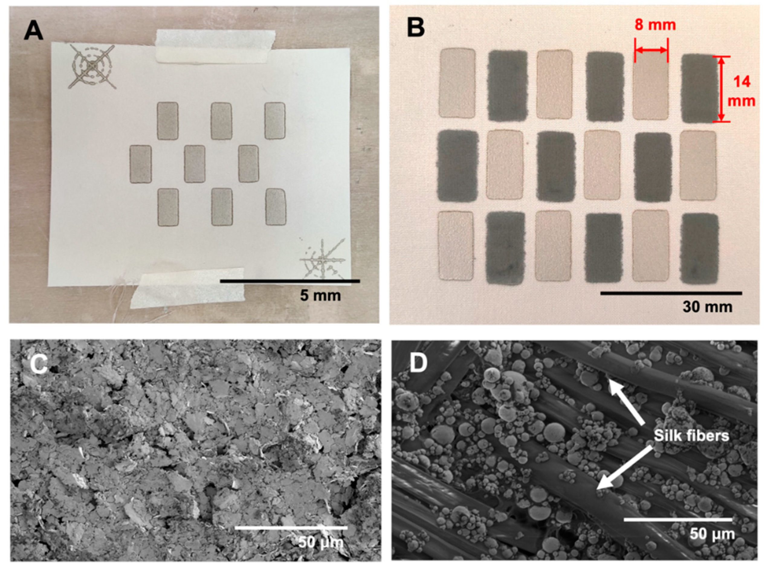
2.2. Nine Cell Battery Fabrication

Nine Ag/AgCl-zinc cells were screen printed on each silk substrate. To enable a larger battery, these Ag/AgCl-Zn cells were connected in a series. The cells were placed in a series using conductive epoxy (Circuit Works 2400) and conductive thread (Adafruit Industries, New York, NY). Then, two wires were cut to approximately 7.6 cm (3″), then stripped to approximately 1.3 cm (0.5″) on each end. Conductive epoxy was used to attach the two wires to the Ag/AgCl cathode and Zn anode to allow for physical connections enabling electrochemical characterization (Figure 2A). These nine cells were placed in a three-by-three arrangement with a medical tape backing on the silk to prevent fluid cross-over while maintaining substrate flexibility, with alternating Ag/AgCl and Zn electrodes. The nine-cell battery generates an open circuit potential of 6.27 ± 0.04 V.

2.3. Cyclic Voltammetry Characterization

The flexible battery is intended for use in biomedical applications with likely exposure to biofluids. The operation of the Ag/AgCl-Zn flexible battery was evaluated post wetting with 1X phosphate-buffered saline (PBS) as the working electrolyte. The operation of the Ag/AgCl-Zn cell wetted with 1X PBS for charge transfer reactions at the both the cathode and the anode was evaluated by cyclic voltammetry (CV). All electrochemical measurements were conducted using a potentiostat (Gamry Interface 1000, Gamry Instruments, Warminster, PA, USA). All measurements were conducted inside a copper mesh Faraday cage to minimize external electrical noise, similar to previous reports [35,36]. Three distinct scan rates of 30 mV/s, 160 mV/s, and 320 mV/s were evaluated to consider the different transport regimes between species diffusion and reaction limited response of the flexible battery [37]. At each scan rate, the measurement was repeated times with variation noted to be less than 1%. The current density was normalized from the area of the Ag/AgCl cathode (1.12 cm2). The electric potential for the CV ranged from −2.6 V to +2.6 V to capture the peaks of the silver and zinc reactions, reported below, based on past reports [14,38]. The three possible reactions at the cathode are [14,38,39,40,41]:
2 AgO + H 2 O + 2 e -     Ag 2 O + 2 OH -  
Ag 2 O + H 2 O + 2 e -     2 Ag + 2 OH -  
AgCl + e -     Ag + Cl -
The possible oxidation reaction at the anode is [38,39]:
Zn + 2 OH -   Zn ( OH ) 2 + 2 e -

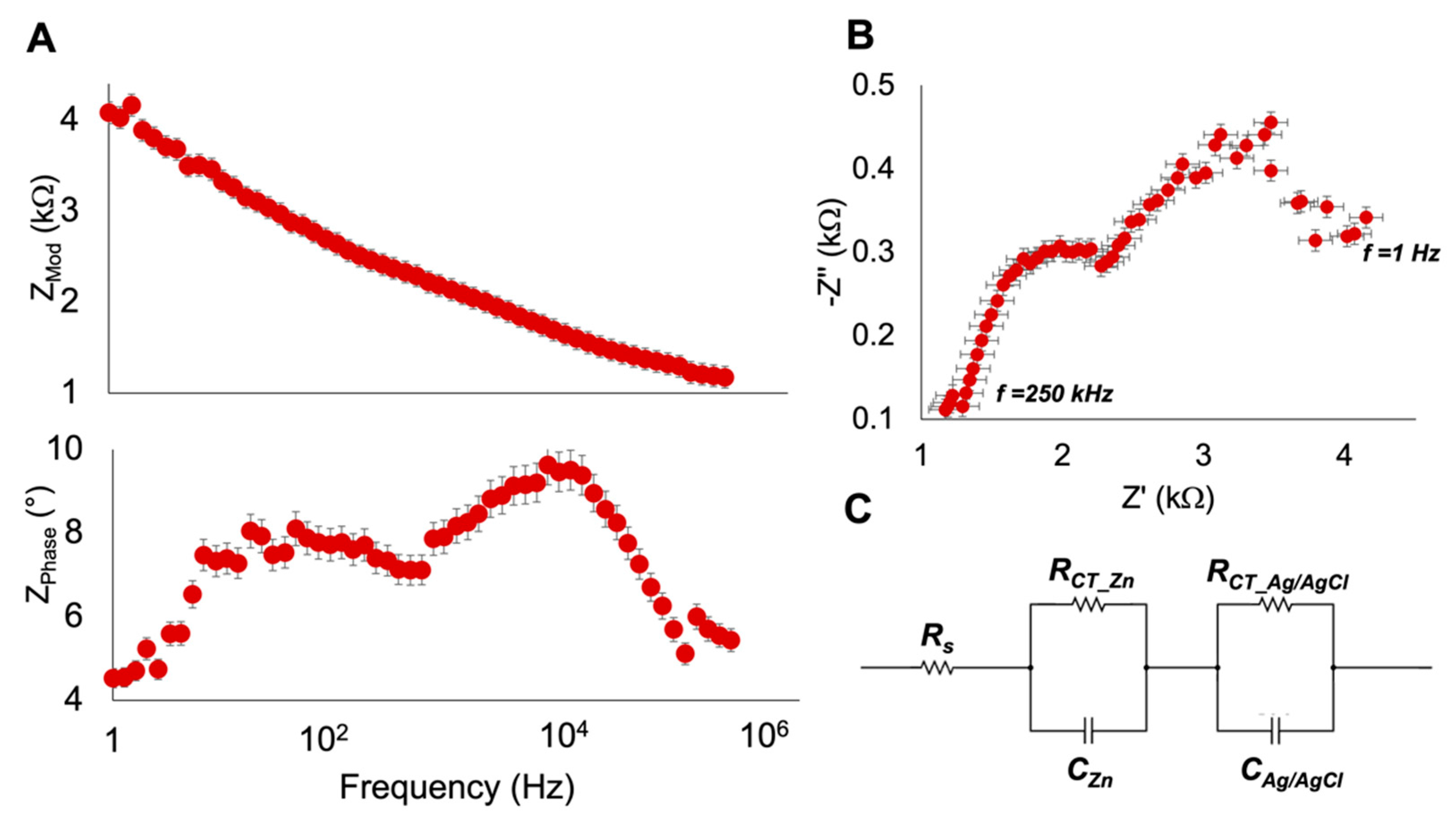
2.4. Electrochemical Impedance Spectroscopy Characterization

Electrochemical Impedance Spectroscopy (EIS) is an electrochemical probing technique that provides information about electrochemical reactions [42]. EIS measurements were performed on the single cell wetted with 1X PBS. The potentiostatic mode was used for the measurements, and in order to elicit a pseudolinear current response, a 10 mV excitation voltage was applied and it recorded over the frequency range of 1 Hz–250 kHz to capture both fast kinetic and slow transport processes. The frequency range falls within the range of frequencies reported previously for similar primary cells [43]. EIS measurements were repeated three times and the results are reported as an average with the associated standard deviation from these measurements.

2.5. Single Cell Discharge and Nine-Cell Battery Operation

The discharge for a single cell was tested to estimate the capacity at a constant current draw until the single cell approached a low operating voltage of 10% of the open circuit voltage. Three constant discharge current densities (0.89 μA/cm2, 8.93 μA/cm2, and 89.29 μA/cm2) were chosen because they are reflective of the typical current draw expected in representative biomedical applications [1,44,45]. Additionally, the operation of the nine-cell battery was evaluated in an unstrained condition (Figure 2A) and on a mannequin to mimic anatomical curvatures present on a human body. Specifically, the nine-cell battery was placed on the quadricep and the gluteus maximus of the mannequin. The battery was affixed to the mannequin using medical tape (Figure 2B) and discharged at 8.93 μA/cm2. Figure 2B indicates the original length of battery l = 5.8 cm, and the strained length l0 = 6.0 cm and l0 = 6.3 cm for the quadricep and gluteus maximus, respectively.

2.6. Sample Application on Soft Tissue Mimic

For a viable demonstration of the nine-cell battery in another potential biomedical application, the battery was positioned unstrained in a gel-plate that has been shown previously as a model for soft tissue injury [10]. The agar gel-plate consists of 3 g of tryptic soy broth (TSB), 1.5 g of agar, and 100 mL of deionized water. The water, TSB, and agar were mixed in a 250 mL beaker and placed on a hot plate at 180 °C. The contents were heated for 25 min while being stirred every 5 min. The gel was then poured into a 15 cm diameter dish and solidified at room temperature after 5 min with a height of 0.70 ± 0.05 cm. Conductive epoxy was used to connect a 12.7 cm (5″) wire from the battery to electrodes of a printed electroceutical dressing that has been used previously to treat chronic wound injuries on dogs and cats [46]. The operation of the nine-cell battery was also tested with 1× PBS as the electrolyte instead of the gel, keeping all other conditions the same. A current-time measurement was conducted using a Keithley 2100 Multimeter (Keithley Instruments, Inc., Cleveland, OH, USA) as shown schematically in Figure 2C.

3. Results and Discussion

3.1. Cyclic Voltammetry Characterization

Cyclic voltammetry of the single Ag/AgCl-Zn cell with 1X PBS as the electrolyte at the three scan rates of 30 mV/s, 160 mV/s, and 320 mV/s are shown in Figure 3A–C, respectively. The change in magnitude of the peak current values (shown explicitly in Figure 3B) at each scan rate indicates the change in charge transfer kinetics when compared against the transport limit due to the diffusion of charged species. A lower scan rate of 30 mV/s (Figure 3A) was investigated to minimize an ohmic response that can arise at higher scan rates [37]. Figure 3A showed two anodic peaks at approximately 0.59 V and 1.76 V. A cathodic current peak was also observed at −0.44 V with a magnitude of −0.8 mA/cm2.
However, at a scan rate of 160 mV/s, two anodic peaks were observed distinctly (Figure 3B) and were attributed to the two Ag reduction reactions (reactions (1) and (2); Methodology and Materials). In Figure 3B, the first anodic peak at 0.96 V indicates that the reaction is limited by diffusion of the species to and from the surface of the electrode whereas the second peak at 2.23 V shows the continuation of charge transfer kinetics at the Ag electrode, not limited by the diffusion layer of the first anodic peak [37,47]. By contrast, the cathodic peak present at 0.27 V represents the oxidation reaction at the Zn electrode (reaction (4); Methodology and Materials) with a diffusion layer limiting the oxidation reaction [37]. The second cathodic peak in Figure 3B at −1.14 V could be attributed to either of the reverse reactions (1) or (2). However, due to the addition of chloride within the system, it is possible that the −1.14 V cathodic peak is the reaction denoted by Equation (3) in the reverse direction (oxidation) as reported previously [39].
Figure 3C displays the CV of the cell at a scan rate of 320 mV/s. The high scan rate was chosen to evaluate the increased diffusion. The anodic peak of 1.97 mA/cm2 at 1.58 V is higher than the largest anodic peak (1.29 mA/cm2) in Figure 3B, but the visual inspection of the curve suggested that the reaction may not be diffusion limited [47]. The location of the peak current values for both the anodic and the cathodic peaks indicates an irreversible system [37] as expected for a primary cell. The observed changes in shape for the voltammograms was attributed to the surface reaction limited by diffusion [47], which influenced differences in peak locations at varying scan rates. Additionally, all the observed peaks were asymmetric around the zero-potential. The asymmetric peaks confirm a non-Nernstian electrochemical response [37] due to the lack of oxidation at the Ag cathode and reduction occurring at the Zn anode in the −2.6 V to 0 V range.

3.2. Electrochemical Impedance Spectroscopy Characterization

EIS for the single Ag/AgCl-Zn cell yielded the corresponding Bode and Nyquist plots as shown in Figure 4A,B, respectively. The Bode plot (Figure 4A) shows the magnitude and phase angle in the 1 Hz to 250 kHz range. The overall impedance magnitude decreases as frequency increases due to the capacitance of the cell being inversely related to the frequency [35]. The phase plot shows partial charge storage as phase angle ranged between 4° and 10°. Each point on the Nyquist plot (Figure 4B) is the impedance at a given frequency as frequency decreases from 250 kHz to 1 Hz. We note, as observed from Figure 4B, the proposed reactions in Equations (1)–(4), lead to multiple relaxation times. Two electrode measurements often produce two semicircles on the Nyquist plot to indicate two individual processes, as seen in Figure 4B [48,49]. The first semicircle (1.1 kΩ–2.3 kΩ on the Z’ axis) represents the oxidation at the Zn electrode and the second semicircle (2.3 kΩ–4.1 kΩ on the Z’ axis) represents the reduction reaction at the Ag/AgCl electrode [49], since the current flows from the anode to the cathode.
To build a phenomenological model of the flexible battery, the electrochemical cell was modeled as an equivalent circuit (Figure 4C) with the circuit parameters obtained by using the Levenberg–Marquardt fitting method (Gamry EChem Analyst). The fitting algorithm was used to calculate the fit values for each component [50]. The goodness of the fit (χ2) was 1.1 × 10⁻². The fit values for each equivalent circuit component are listed in Table 1. This circuit was developed from other electrode–electrolyte interface equivalent circuit models that account for charge storage at electrodes as well as the charge transfer and solution resistance from the electrolyte [49,51,52]. There were three resistive components in this circuit, the solution resistance (Rs), the charge transfer resistance at the Zn anode (RCT_Zn), and the charge transfer resistance at the Ag/AgCl cathode (RCT_Ag/AgCl) with fit values of 1.29 × 10³ Ω, 8.95 × 10² Ω, and 1.37 × 10³ Ω, respectively. The electrode capacitance obtained through the fit (CZn and CAg/AgCl) were 7.18 × 10⁻⁸ F and 3.78 × 10⁻⁶ F as summarized in Table 1. A Warburg impedance component was not used in this model since it was shown experimentally that is does not attribute to the overall impedance, which can be concluded from the absence of the straight 45° line to the abscissa.

3.3. Cell Discharge and Battery Flexibility Evaluation

The electrochemical cell was discharged at 0.89 μA/cm2, 8.93 μA/cm2, and 89.29 μA/cm2, representing common current flows reported for biomedical applications [1,35,50]. For a single cell of the Ag/AgCl- Zn battery, the open circuit potential was 0.81 ± 0.04 V. The slopes of the discharge curves were 0.0024 V/min, 0.0029 V/min, and 0.012 V/min for the 0.89 μA/cm2, 8.93 μA/cm2, and 89.29 μA/cm2 current densities, respectively. At 8.93 μA/cm2 and 89.29 μA/cm2, the battery cell discharged to 81 mV (representing a 10× drop in the open circuit potential), in 240 min and 37.5 min, respectively. However, after four hours (matching the 8.93 μA/cm2 discharge time), the 0.89 μA/cm2 discharge current density reached a final potential of 220 mV.
The single-cell battery has an area capacity of 0.36 mAh/cm2 when discharged, which has a higher value than a previously reported flexible Ag-Zn battery [14], demonstrating an advancement to the current state of art. Some other flexible Ag-Zn batteries have higher capacities [15,26,43,53,54]. However, these higher capacity batteries use significantly higher concentration electrolytes (5 M–10 M) with high conductivity salts which are rarely biocompatible [55]. However, for the intended application of this battery, using a viable biofluid is essential.
The nine-cell battery demonstrated an open circuit potential of 6.27 ± 0.04 V and was discharged at 0.89 μA/cm2, 8.93 μA/cm2, and 89.29 μA/cm2 constant current density in the unstrained position. The three reported discharge current densities for the test system (cf. Figure 2) corresponds to a constant current draw of 1 μA, 10 μA, and 100 μA, respectively. At the 0.89 μA/cm2, 8.93 μA/cm2, and 89.29 μA/cm2 rates, the unflexed battery discharged to 627 mV (representing a 10× drop in the open circuit potential) in 39 min, 62 min, and 4 min, respectively. Notably, under these discharge conditions, for the nine-cell battery tested with biologically relevant electrolytes, a constant current draw of 10 µA appeared to be the most stable current flow condition. The net current flow is dependent on the system to be tested and the specific systemic resistances with a significant range of values reported for electrolyte type, draw currents, and therefore subsequent discharge rates for similar Ag-Zn batteries [14,15,26,43,53,54]. However, for the suggested applications in this work, a longer discharge time is preferred at the most stable current flow. Therefore, the 8.93 μA/cm2 rate was chosen to evaluate the nine-cell strained batteries since it had the longest time to discharge indicating a more stable current draw for the battery. The flexible battery was wrapped over the mannequin’s quadricep and gluteus maximus representing a potential application condition where the planar geometry is under mechanical strain during operation for a wearable device. The quadricep and gluteus maximus strained batteries discharged in 48 min and 32 min, respectively. The discharge times are tabulated in Table 2. Battery deformation can influence contact resistance, ion diffusion, and the structural stability of the battery [19]. To evaluate the effect of mechanical strain, EIS was repeated for the nine-cell battery and fit to the circuit shown in Figure 4C. The solution resistance and charge transfer resistance at the electrodes increased while the capacitance decreased for each electrode (Table 2).

3.4. Sample Application on Soft Tissue Mimic

As the 8.93 μA/cm2 discharge density provided the longest, reliable operation for the battery operating under strain, an additional experiment for the unstrained nine-cell battery for an in vitro demonstration on a soft tissue mimic was conducted. The generated current with the 1× PBS as the liquid electrolyte showed a decline from 150 μA to 25 μA after 100 min, followed by a further decline to 10 μA after approximately 150 min (Figure 5A).
A similar experiment with an agar gel representing a soft tissue with effluent for use of electroceuticals, showed that the starting current draw was 380 μA and decreased to 10 μA after 95 min (Figure 5B). The agar gel presents a porous electrolyte with a higher ionic strength (~0.15 M) compared to a liquid electrolyte at lower ionic strength (0.01 M) for 1× PBS. The difference in initial current draw was attributed to the difference in properties of the electrolytes. Previous results for electrolytes with higher ionic strengths, such as the agar gel, have shown improved system performance due to the increase in conductivity [56]. This experiment validates the flexible battery’s ability to provide current to the PED in a soft tissue environment, which is necessary for wound healing applications.

4. Conclusions

A flexible, easily fabricated, and biocompatible Ag/AgCl-Zn battery was evaluated under a variety of conditions to demonstrate potential in biomedical applications where biofluid exposure is likely. Detailed electrochemical characterization was reported using two established techniques in cyclic voltammetry, which showed the competition between chemical species diffusion and charge transfer by varying the scan rates and confirmed the irreversibility of a primary cell. Second, electrochemical impedance spectroscopy showed the storage of charge within each electrode. In addition, the discharge curves provided another metric on the operation of the battery. Nine Ag/AgCl-Zn cells were connected in series on the same silk substrate and fluidically isolated to generate a higher open circuit potential. The nine-cell battery was evaluated in two mechanically strained configurations during operation with a biologically relevant fluid and immersed in a gel mimicking soft tissue to evaluate current flow. In all potential demonstrations of the battery, a feasible operation was noted as described in the results section. The primary purpose of this manuscript was to report the feasibility and viability of using a primary battery such as the Ag-Zn system reported here in biomedical applications where biofluid exposure is possible, which has been demonstrated. However, as noted in the manuscript, developing continuous Zn electrodes, adjusting the electrode spacing, and optimizing battery performance are yet unmet. Clearly, future work requires careful optimization to yield longer operation times.

Author Contributions

Conceptualization, S.P. and R.H.; methodology, S.P. and R.H.; formal analysis, D.B. and R.H.; data curation, D.B.; writing—original draft preparation, D.B. and R.H.; writing—review and editing, D.B., R.H., S.P. and J.F.D.; supervision, S.P.; project administration, S.P. All authors have read and agreed to the published version of the manuscript.

Funding

This research was funded by the National Institute of Health, grant number R01HL141941.

Data Availability Statement

The data is available on request.

Acknowledgments

We thank The Ohio State University Infectious Disease Institute. We acknowledge support from the staff at campus microscopy and imaging facility (CMIF) that is supported in part by grant P30 CA016058, National Cancer Institute, Bethesda, MD. We also acknowledge the center for electron microscopy and analysis (CEMAS) at The Ohio State University for assistance in various imaging and experimental aspects of this research effort. We thank J.H. Kim at the Ohio State University for multiple insightful conversations.

Conflicts of Interest

The authors declare no conflict of interest.

References

  1. Heald, R.; Bennett, M.; Subramaniam, V.V.; Dusane, D.; Lochab, V.; Sundaram, P.M.; Salyer, S.; West, J.; Stoodley, P.; Prakash, S. Printed Electroceutical Dressings for the Inhibition of Biofilms and Treatment of Chronic Wounds. J. Microelectromech. Syst. 2020, 29, 918–923. [Google Scholar] [CrossRef] [PubMed]
  2. Leal, C.; Lopes, P.A.; Serra, A.; Coelho, J.F.; de Almeida, A.T.; Tavakoli, M. Untethered disposable health monitoring electronic patches with an integrated Ag2O–Zn battery, a AgInGa current collector, and hydrogel electrodes. ACS Appl. Mater. Interfaces 2019, 12, 3407–3414. [Google Scholar] [CrossRef]
  3. Best, J. Wearable technology: COVID-19 and the rise of remote clinical monitoring. BMJ 2021, 372, n413. [Google Scholar] [CrossRef] [PubMed]
  4. Nag, A.; Mukhopadhyay, S.C.; Kosel, J. Wearable flexible sensors: A review. IEEE Sens. J. 2017, 17, 3949–3960. [Google Scholar] [CrossRef]
  5. Gao, J.; Shang, K.; Ding, Y.; Wen, Z. Material and configuration design strategies towards flexible and wearable power supply devices: A review. J. Mater. Chem. A 2021, 9, 8950–8965. [Google Scholar] [CrossRef]
  6. Howe, D.; Dunning, J.; Zorman, C.; Garverick, S.; Bogie, K. Development of an integrated surface stimulation device for systematic evaluation of wound electrotherapy. Ann. Biomed. Eng. 2015, 43, 306–313. [Google Scholar] [CrossRef]
  7. Barki, K.G.; Das, A.; Dixith, S.; Ghatak, P.D.; Mathew-Steiner, S.; Schwab, E.; Khanna, S.; Wozniak, D.J.; Roy, S.; Sen, C.K. Electric field based dressing disrupts mixed-species bacterial biofilm infection and restores functional wound healing. Ann. Surg. 2019, 269, 756. [Google Scholar] [CrossRef]
  8. Kambouris, M.E.; Markogiannakis, A.; Arabatzis, M.; Manoussopoulos, Y.; Kantzanou, M.; Velegraki, A. Wireless electrostimulation: A new approach in combating infection? Future Microbiol. 2017, 12, 255–265. [Google Scholar] [CrossRef]
  9. Banerjee, J.; Ghatak, P.D.; Roy, S.; Khanna, S.; Hemann, C.; Deng, B.; Das, A.; Zweier, J.L.; Wozniak, D.; Sen, C.K. Silver-zinc redox-coupled electroceutical wound dressing disrupts bacterial biofilm. PLoS ONE 2015, 10, e0119531. [Google Scholar] [CrossRef]
  10. Lochab, V.; Jones, T.H.; Dusane, D.H.; Peters, C.W.; Stoodley, P.; Wozniak, D.J.; Subramaniam, V.V.; Prakash, S. Ultrastructure imaging of Pseudomonas aeruginosa lawn biofilms and eradication of the tobramycin-resistant variants under in vitro electroceutical treatment. Sci. Rep. 2020, 10, 9879. [Google Scholar] [CrossRef]
  11. Dowlatababdi, F.H.; Amiri, G.; Mohammadi Sichani, M. Investigation of the antimicrobial effect of silver doped Zinc Oxide nanoparticles. Nanomed. J. 2017, 4, 50–54. [Google Scholar]
  12. Xiao, X.; Liu, E.; Shao, J.; Ge, S. Advances on biodegradable zinc-silver-based alloys for biomedical applications. J. Appl. Biomater. Funct. Mater. 2021, 19, 22808000211062407. [Google Scholar] [CrossRef] [PubMed]
  13. Chae, J.S.; Park, S.K.; Roh, K.C.; Park, H.S. Electrode materials for biomedical patchable and implantable energy storage devices. Energy Storage Mater. 2020, 24, 113–128. [Google Scholar] [CrossRef]
  14. Garcia, D.M.E.; Pereira, A.S.T.M.; Almeida, A.C.; Roma, U.S.; Soler, A.B.A.; Lacharmoise, P.D.; Ferreira, I.M.d.M.; Simão, C.C.D. Large-Area Paper Batteries with Ag and Zn/Ag Screen-Printed Electrodes. ACS Omega 2019, 4, 16781–16788. [Google Scholar] [CrossRef]
  15. Braam, K.T.; Volkman, S.K.; Subramanian, V. Characterization and optimization of a printed, primary silver–zinc battery. J. Power Sources 2012, 199, 367–372. [Google Scholar] [CrossRef]
  16. National Center for Biotechnology Information. PubChem compound summary for CID 14797, potassium hydroxide. In PubChem; National Center for Biotechnology Information: Bethesda, MD, USA, 2022. [Google Scholar]
  17. Karpinski, A.; Makovetski, B.; Russell, S.; Serenyi, J.; Williams, D. Silver–zinc: Status of technology and applications. J. Power Sources 1999, 80, 53–60. [Google Scholar] [CrossRef]
  18. Mauger, A.; Julien, C. Critical review on lithium-ion batteries: Are they safe? Sustainable? Ionics 2017, 23, 1933–1947. [Google Scholar] [CrossRef]
  19. Sepúlveda, A.; Speulmanns, J.; Vereecken, P.M. Bending impact on the performance of a flexible Li4Ti5O12-based all-solid-state thin-film battery. Sci. Technol. Adv. Mater. 2018, 19, 454–464. [Google Scholar] [CrossRef]
  20. Hu, L.; Wu, H.; La Mantia, F.; Yang, Y.; Cui, Y. Thin, flexible secondary Li-ion paper batteries. ACS Nano 2010, 4, 5843–5848. [Google Scholar] [CrossRef]
  21. Kang, K.-Y.; Lee, Y.-G.; Shin, D.O.; Kim, J.-C.; Kim, K.M. Performance improvements of pouch-type flexible thin-film lithium-ion batteries by modifying sequential screen-printing process. Electrochim. Acta 2014, 138, 294–301. [Google Scholar] [CrossRef]
  22. Fang, Z.; Wang, J.; Wu, H.; Li, Q.; Fan, S.; Wang, J. Progress and challenges of flexible lithium ion batteries. J. Power Sources 2020, 454, 227932. [Google Scholar] [CrossRef]
  23. Gellner, S.; Schwarz-Pfeiffer, A.; Nannen, E. Textile-Based Battery Using a Biodegradable Gel-Electrolyte. Proceedings 2021, 68, 17. [Google Scholar]
  24. Cheng, Q.; Song, Z.; Ma, T.; Smith, B.B.; Tang, R.; Yu, H.; Jiang, H.; Chan, C.K. Folding paper-based lithium-ion batteries for higher areal energy densities. Nano Lett. 2013, 13, 4969–4974. [Google Scholar] [CrossRef] [PubMed]
  25. Ma, J.; Li, Y.; Grundish, N.S.; Goodenough, J.B.; Chen, Y.; Guo, L.; Peng, Z.; Qi, X.; Yang, F.; Qie, L. The 2021 battery technology roadmap. J. Phys. D Appl. Phys. 2021, 54, 183001. [Google Scholar] [CrossRef]
  26. Li, Y.; Yong, S.; Hillier, N.; Arumugam, S.; Beeby, S. Screen printed flexible water activated battery on woven cotton textile as a power supply for e-textile applications. IEEE Access 2020, 8, 206958–206965. [Google Scholar] [CrossRef]
  27. Joung, Y.-H. Development of implantable medical devices: From an engineering perspective. Int. Neurourol. J. 2013, 17, 98. [Google Scholar] [CrossRef]
  28. Park, H.-K.; Kong, B.-S.; Oh, E.-S. Effect of high adhesive polyvinyl alcohol binder on the anodes of lithium ion batteries. Electrochem. Commun. 2011, 13, 1051–1053. [Google Scholar] [CrossRef]
  29. Chaouat, M.; Le Visage, C.; Baille, W.E.; Escoubet, B.; Chaubet, F.; Mateescu, M.A.; Letourneur, D. A novel cross-linked poly (vinyl alcohol)(PVA) for vascular grafts. Adv. Funct. Mater. 2008, 18, 2855–2861. [Google Scholar] [CrossRef]
  30. Abdal-Hay, A.; Hussein, K.H.; Casettari, L.; Khalil, K.A.; Hamdy, A.S. Fabrication of novel high performance ductile poly (lactic acid) nanofiber scaffold coated with poly (vinyl alcohol) for tissue engineering applications. Mater. Sci. Eng. C 2016, 60, 143–150. [Google Scholar] [CrossRef]
  31. Vilkhu, R.; Thio, W.J.-C.; Ghatak, P.D.; Sen, C.K.; Co, A.C.; Kiourti, A. Power generation for wearable electronics: Designing electrochemical storage on fabrics. IEEE Access 2018, 6, 28945–28950. [Google Scholar] [CrossRef]
  32. Fan, L.; Guo, Z.; Zhang, Y.; Wu, X.; Zhao, C.; Sun, X.; Yang, G.; Feng, Y.; Zhang, N. Stable artificial solid electrolyte interphase films for lithium metal anode via metal–organic frameworks cemented by polyvinyl alcohol. J. Mater. Chem. A 2020, 8, 251–258. [Google Scholar] [CrossRef]
  33. Zhao, Y.; Wang, D.; Gao, Y.; Chen, T.; Huang, Q.; Wang, D. Stable Li metal anode by a polyvinyl alcohol protection layer via modifying solid-electrolyte interphase layer. Nano Energy 2019, 64, 103893. [Google Scholar] [CrossRef]
  34. Heald, R. Development and Evaluation of a Smart Platform for Engineered Electroceutical Dressings (SPEEDs). Master’s Thesis, The Ohio State University, Columbus, OH, USA, 2021. [Google Scholar]
  35. Porter, F.C. Zinc Handbook: Properties, Processing, and Use in Design; CRC Press: Boca Raton, FL, USA, 1991. [Google Scholar]
  36. Dusane, D.H.; Lochab, V.; Jones, T.; Peters, C.W.; Sindeldecker, D.; Das, A.; Roy, S.; Sen, C.K.; Subramaniam, V.V.; Wozniak, D.J. Electroceutical treatment of Pseudomonas aeruginosa biofilms. Sci. Rep. 2019, 9, 2008. [Google Scholar] [CrossRef] [PubMed]
  37. Elgrishi, N.; Rountree, K.J.; McCarthy, B.D.; Rountree, E.S.; Eisenhart, T.T.; Dempsey, J.L. A practical beginner’s guide to cyclic voltammetry. J. Chem. Educ. 2018, 95, 197–206. [Google Scholar] [CrossRef]
  38. McBreen, J.; Gannon, E. The electrochemistry of metal oxide additives in pasted zinc electrodes. Electrochim. Acta 1981, 26, 1439–1446. [Google Scholar]
  39. Lǎzǎrescu, V.; Radovici, O.; Vass, M. Voltammetric studies on anodic oxidation of silver. Electrochim. Acta 1985, 30, 1407–1408. [Google Scholar] [CrossRef]
  40. Ozgit, D.; Hiralal, P.; Amaratunga, G.A. Improving performance and cyclability of zinc–silver oxide batteries by using graphene as a two dimensional conductive additive. ACS Appl. Mater. Interfaces 2014, 6, 20752–20757. [Google Scholar] [PubMed]
  41. Lochab, V.; Jones, T.H.; Alkandry, E.; West, J.D.; Abdel-Rahman, M.H.; Subramaniam, V.V.; Prakash, S. Evaluation of electrical properties of ex vivo human hepatic tissue with metastatic colorectal cancer. Physiol. Meas. 2020, 41, 085005. [Google Scholar] [CrossRef]
  42. Vitarelli Jr, M.J.; Prakash, S.; Talaga, D.S. Determining nanocapillary geometry from electrochemical impedance spectroscopy using a variable topology network circuit model. Anal. Chem. 2011, 83, 533–541. [Google Scholar] [CrossRef]
  43. Kota, A.; Gogia, A.; Neidhard-Doll, A.T.; Chodavarapu, V.P. Printed Textile-Based Ag2O–Zn Battery for Body Conformal Wearable Sensors. Sensors 2021, 21, 2178. [Google Scholar]
  44. Bard, A.J.; Faulkner, L.R. Electrochemical methods fundamentals and applications. Surf. Technol. 1983, 20, 91–92. [Google Scholar]
  45. Peng, J.; Deng, Y.; Wang, D.; Jin, X.; Chen, G.Z. Cyclic voltammetry of electroactive and insulative compounds in solid state: A revisit of AgCl in aqueous solutions assisted by metallic cavity electrode and chemically modified electrode. J. Electroanal. Chem. 2009, 627, 28–40. [Google Scholar] [CrossRef]
  46. Heald, R.; Salyer, S.; Ham, K.; Wilgus, T.A.; Subramaniam, V.V.; Prakash, S. Electroceutical treatment of infected chronic wounds in a dog and a cat. Vet. Surg. 2022, 51, 520–527. [Google Scholar] [CrossRef] [PubMed]
  47. Gamry Instruments, I. Application Note Rev. 1.0. Available online: https://www.gamry.com/application-notes/EIS/category/Electrochemical+Impedance+Spectroscopy (accessed on 25 September 2022).
  48. Veal, B.W.; Baldo, P.M.; Paulikas, A.P.; Eastman, J.A. Understanding Artifacts in Impedance Spectroscopy. J. Electrochem. Soc. 2014, 162, H47–H57. [Google Scholar] [CrossRef]
  49. Middlemiss, L.A.; Rennie, A.J.R.; Sayers, R.; West, A.R. Characterisation of batteries by electrochemical impedance spectroscopy. Energy Rep. 2020, 6, 232–241. [Google Scholar] [CrossRef]
  50. Zamarayeva, A.M.; Gaikwad, A.M.; Deckman, I.; Wang, M.; Khau, B.; Steingart, D.A.; Arias, A.C. Fabrication of a High-Performance Flexible Silver–Zinc Wire Battery. Adv. Electron. Mater. 2016, 2, 1500296. [Google Scholar] [CrossRef]
  51. Chang, B.-Y.; Park, S.-M. Integrated Description of Electrode/Electrolyte Interfaces Based on Equivalent Circuits and Its Verification Using Impedance Measurements. Anal. Chem. 2006, 78, 1052–1060. [Google Scholar] [CrossRef]
  52. Franks, W.; Schenker, I.; Schmutz, P.; Hierlemann, A. Impedance Characterization and Modeling of Electrodes for Biomedical Applications. IEEE Trans. Bio-Med. Eng. 2005, 52, 1295–1302. [Google Scholar] [CrossRef]
  53. Kumar, R.; Shin, J.; Yin, L.; You, J.-M.; Meng, Y.; Wang, J. All-Printed, Stretchable Zn-Ag2O Rechargeable Battery via, Hyperelastic Binder for Self-Powering Wearable Electronics. Adv. Energy Mater. 2016, 7, 1602096. [Google Scholar] [CrossRef]
  54. Berchmans, S.; Bandodkar, A.J.; Jia, W.; Ramírez, J.; Meng, Y.S.; Wang, J. An epidermal alkaline rechargeable Ag–Zn printable tattoo battery for wearable electronics. J. Mater. Chem. A 2014, 2, 15788–15795. [Google Scholar] [CrossRef]
  55. Stauss, S.; Honma, I. Biocompatible batteries—Materials and chemistry, fabrication, applications, and future prospects. Bull. Chem. Soc. Jpn. 2018, 91, 492–505. [Google Scholar] [CrossRef]
  56. Zhang, W.; Chen, X.; Wang, Y.; Wu, L.; Hu, Y. Experimental and Modeling of Conductivity for Electrolyte Solution Systems. ACS Omega 2020, 5, 22465–22474. [Google Scholar] [CrossRef] [PubMed]
Figure 1. (A) The resulting Ag/AgCl electrodes. (B) The resulting cured Ag/AgCl and Zn electrodes. The nominal electrode dimensions are seen in the figure. (C) Scanning electron microscopy (SEM) image to show the microstructure of printed and cured Ag/AgCl cathode. (D) SEM image to show the microstructure of printed and cured Zn anode with the underlying silk fibers.
Energies 15 07167 g001
Figure 2. (A) Experimental setup of the nine-cell battery in an unstrained state in the Faraday cage. (B) Experimental setup of the nine-cell battery on the quadricep of the mannequin with a visual of the length dimensions used to calculate the strain. (C) Exploded view of the agar gel, PED [1], and flexible battery to depict the current flow that was measured experimentally with the Keithley 2100 Multimeter.
Energies 15 07167 g002
Figure 3. Cyclic voltammetry of the Ag/AgCl-Zn cell at scan rates of (A) 30 mV/s, (B) 160 mV/s, (C) 320 mV/s. The potential was swept from −2.6 V to +2.6 V, then reversed.
Energies 15 07167 g003
Figure 4. EIS for the screen-printed battery (A) The Bode plot that shows impedance modulus and phase as a function of the probing frequency (1 Hz–250 kHz). (B) The Nyquist plot for the cell over the same frequency range, and (C) The equivalent circuit used for a fit to generate values in Table 1 for the cell.
Energies 15 07167 g004
Figure 5. Testing the battery performance in possible biomedical applications. The plots show current-time measurement for the (A) 1× PBS electrolyte, (B) Gel electrolyte.
Energies 15 07167 g005
Table 1. Equivalent Circuit Values for a Single Cell Battery.
ComponentValue
RS1.29 × 103 Ω ± 10.9 Ω
CZn7.18 × 10−8 F ± 5.23 × 10⁻⁹ F
RCT_Zn8.95 × 102 Ω ± 19.8 Ω
CAg/AgCl3.78 × 10−6 F ± 2.44 × 10⁻⁷ F
RCT_Ag/AgCl1.37 × 103 Ω ± 31.9 Ω
Table 2. Equivalent Circuit Fit Values for the Flat, Quadricep, and Gluteus Maximus Strained 9-Cell Battery.
ComponentFlatQuadricepGluteus
Maximus
Discharge Time62 min48 min32 min
RS4.30 × 103 Ω ± 5.97 × 10² Ω8.50 × 10³ Ω ± 80.0 Ω7.20 × 10³ Ω ± 94.5 Ω
CZn2.71 × 10−8 F ± 7.63 × 10⁻⁹ F9.09 × 10−9 F ± 9.12 × 10⁻¹⁰ F5.06 × 10−9 F ± 2.70 × 10⁻¹⁰ F
RCT_Zn1.39 × 103 Ω ± 4.18 × 10² Ω2.45 × 10³ Ω ± 1.13 × 10² Ω5.15 × 10³ Ω ± 1.30 × 10² Ω
CAg/AgCl1.98 × 10−6 F ± 3.35 × 10⁻⁷ F6.44 × 10−7 F ± 5.24 × 10⁻⁸ F3.59 × 10−7 F ± 2.30 × 10⁻⁸ F
RCT_Ag/AgCl3.09 × 103 Ω ± 88.8 Ω3.65 × 10³ Ω ± 1.37 × 10² Ω5.69 × 10³ Ω ± 1.56 × 10² Ω
Publisher’s Note: MDPI stays neutral with regard to jurisdictional claims in published maps and institutional affiliations.

