Abstract
The microchannel heat exchanger is one of the most compact and effective heat exchangers used for cooling devices in building air conditioning system, while application of nanofluids in microchannel further enhance its thermal performance due to its much higher thermal conductivity. Considering the continuous rapid increase in energy consumption in the building sector, especially in air conditioning systems, the heat transfer performance of a microchannel with nanofluids should be further enhanced to realize energy savings. This study analyzes the influence of combining nanofluid and flow disturbance structure on the heat transfer enhancement of a microchannel, which is also the noted novelty. A rectangular grooved microchannel (RGMC) is proposed, and its thermal performance using Al2O3/water nanofluids is investigated using the CFD method, with the mixture model to simulate the Al2O3/water nanofluids considering the slip velocity between the base fluid and nanoparticles. The results show that at 1.5 m/s, Nu of RGMC with 2 vol% nanofluids is 38.5% larger than that of smooth microchannel (SMC) with the same nanofluids, and 36.7% larger than that of RGMC with pure water, indicating the much better heat transfer performance of the novel designed RGMC structure. The maximum temperature for RGMC is 5 K lower than SMC with 2 vol% Al2O3/water nanofluid at inlet velocity of 1.5 m/s. Further analysis on the integrated effect between fluid flow and heat transfer shows that the synergy angle β near the center line of RGMC is much lower than that of SMC, representing that the better thermal performance is caused by the flow structured induced by the grooves. Moreover, at 1.5 m/s, βα of SMC with 2 vol% nanofluid is 89.4 Deg, which is 1.66 Deg higher than the βα value of RGMC, while at 0.25 m/s, the βα of two types of microchannel are close to each other. This indicates that the groove structure shows greater enhancement at higher inlet velocity. It is concluded that combining nanofluid and groove structure can significantly enhance heat transfer of the microchannel. The nanofluid enhances heat transfer at lower inlet velocity, while the groove structure enhances it at higher inlet velocity. This study will be helpful for the design of a high-efficiency microchannel heat exchanger that promotes building energy savings.
1. Introduction
Heat exchangers are one of the most important components of a cooling system such as building air conditioning system. The efficiency of a heat exchanger significantly determines the cooling performance and economic efficiency. Microchannel heat sink is one of the most compact and powerful cooling apparatuses used to deal with this issue [1]. Tuckerman and Pease [2] first designed and tested a rectangular microchannel heat sink to cool down the integrated circuits. The allowable heat flux was reported as high as 1700 W/cm2, with only a 70 °C temperature rise of the micro-chip. Guo et al. [3] studied the size effect on the thermal as well as the hydro-dynamic performance of microscale single-phase fluids and found that the flow continuity hypothesis holds in most cases when the characteristic length of microchannel is 1 μm~1 mm. Herwig et al. [4] believed that in spite of microscale effects, the microscale system basically follows the flow characteristics in a macrosystem. It indicated the validation of continuous hypothesis and a viscous flow model to describe the phenomenon in a microchannel.
Single-phase fluids such as deionized water are often used as coolants in microchannels [5,6,7,8]. Due to the limited cooling ability of conventional coolants such as deionized water and ethylene glycol, it may not meet the heat dissipation demand for high heat flux condition. Choi and Eastman [9] firstly introduced nanofluid to this issue, which is nanoparticles suspended in the base fluid. Heat transfer was found to be enhanced due to the higher thermal conductivity of nanofluid compared to the pure base fluid [10]. In their experiment, Thansekhar et al. [11] found that a higher volume concentration of nanofluid provides a better heat transfer performance, while the additional pressure drop caused by nanofluid is not very high. Li et al. [12] found that Al2O3-water nanofluid has a significant effect on thermal performance; however it has the disadvantage of increasing energy consumption. In their experiment, Nguyen et al. [13] found that the heat transfer coefficient using nanoparticles with a diameter of 36 nm is higher than that of 47 nm. Varun Kumar et al. [14] numerically investigated the hybrid nanofluid over a curved stretchable surface, and found that the hybrid nanofluid exhibits better thermal performance than the conventional one due to its improved heat source parameter. Additionally, non-Newtonian nanofluid [15], magnetized flow of sutterby nanofluid [16], and dusty hybrid nanofluid [17,18] are leading a new trend.
Lots of efforts have been taken to model the heat transfer and flow phenomenon of nanofluids in microchannels. The mostly used single-phase model is based on assumption of thermal equilibrium between fluid phase and particles, as well as no slip velocity between them [19]. Then, the fluid properties only need to be calculated before simulation. However, the simple assumptions may cause deviation by neglecting mixing effects between two phases. Yet, the advanced two-phase mixture models allow interpenetrating phases, which means that each phase has a velocity and volume fraction of its own. Akbari et al. [20] comparatively studied a single-phase model and several two-phase models (mixture, VOF and Eulerian models). The results show that using two-phase models predicts more accurately than using the others compared with the experimental data. Similar results were found by Fard et al. [21], who studied the nanofluids in a circular tube. Additionally, Moraveji et al. [22] studied laminar forced convection of nanofluids using the four models. The results show that the mixture model is the best choice, considering aspects such as high accuracy, less CPU usage and running time. Naveen Kumar et al. [23] studied the viscosity and effective thermal conductivity of CuO-water nanofluid using the Koo–Kleinstreuer–Li (KKL) model. They also exploded the rheological properties of the nanofluids using the Koo–Kleinstreuer–Li model in another work [24]. Using nanofluids as coolant in microchannels can effectively improve the heat transfer capacity of microchannels. However, the ability of nanofluids to improve the heat transfer of microchannels is also limited.
Structural optimization is also considered for improving the performance of microchannel heat sink. Xia et al. [25] studied microchannels with concave cavities and revealed the mechanism of thermal performance enhancement. Li et al. [26] analyzed the field synergy characteristics of the microchannel with non-uniform cavities. It was found that the improvement in the field synergy contributes to the heat transfer enhancement. Inserting micro ribs into the walls exhibits more obvious improvement than cavities. Chen et al. [27] experimentally studied the effects of different triangular prisms on the thermal as well as hydro-dynamic characteristics. The backward triangular prism has the best comprehensive performance compared to the other designs. Naqiuddin et al. [28] proposed a novel segmented microchannel heat sink based on the rectangular one. The Taguchi grey method is adopted to optimize the structural parameters of the heat sink. Chai et al. [29] numerically investigated the microchannel heat sink with offset ribs, of which the Nusselt number and friction factor were 1.42–1.95 and 1.93–4.57 times greater than those of the smooth one. The advantage of the offset ribs is obvious under low Reynolds number condition, where the pressure drop is not too high. Hong et al. [30] studied a microchannel with uniformly offset fins, which facilitate the diffusion of the thermal boundary layer. Generally, inserting a fluid-disturbing structure can effectively enhance the heat transfer. However, the shapes [29], inserting locations and angles [31], as well as the size parameters [32], also significantly affect the heat transfer of microchannel heat sinks, which requires the novel and effective structure considering all these effects. Based on the previous optimization studies, this paper proposes a novel structure of periodically arranged asymmetric microgrooves, of which the rectangular grooves are adopted for its comprehensive performance and longer periodic distance than conventionally considered for the sake of lower flow resistance.
According to the above, the heat transfer of nanofluids in microchannels needs to be further improved. Therefore, a microchannel combined with rectangular grooves to disturb the nanofluids for heat transfer enhancement is proposed in this study. The thermal performance of the nanofluids in a microchannel is numerically investigated using the CFD method based on the mixture model. A following comparative study between the proposed rectangular grooved microchannel (RGMC) and a conventional smooth microchannel (SMC) is conducted, and various volume fractions of the nanofluid are considered. Hence, the novelty of this study lies in two aspects: one is the novel design of the rectangular groove on the channel wall to enhance the nanofluid heat transfer, and the other is the analysis of the integrated effect of rectangular groove on temperature and flow fields using field synergy theory. The results can provide a new reference for the heat transfer optimization of the microchannels using nanofluid.
2. Numerical Method
2.1. Geometric Model
The microchannel with rectangular grooves (RGMC) is based on the smooth microchannel heat sink (SMC) according to a previous study by Lee et al. [33], as shown in Figure 1. The experimental data are used to verify the simulation method. The basic microchannel heat sink consists of 21 parallel channels, a cover plate, side walls and a base plate. The schematic diagram is shown in Figure 1. For the novel structure, the periodically arranged asymmetric microgrooves are performed on the channel walls, of which the rectangular grooves are adopted, and a longer periodic distance than conventional is considered for the sake of lower flow resistance, as shown in Figure 1b.
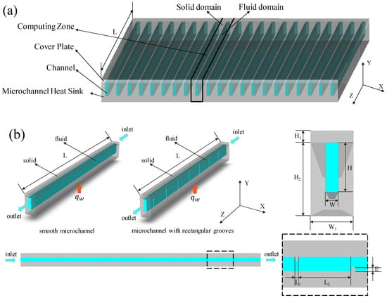
Figure 1.
Geometry model of the microchannel. (a) Integrated model of microchannel heat sink. (b) Schematic diagram of computing zone for microchannel heat sink.
To reduce the computing cost and to focus on the main point of this study, one channel is selected as the computing zone, as shown in Figure 1a, which includes two domains: the solid domain (channel wall) and the fluid domain (channel). Sketches of the computing zone can be seen in Figure 1b. A constant heat flux qw locates at the bottom surface of heat sink. The material of solid components is copper, while the cover plate is made of polycarbonate plastic.
Two smooth microchannels are designed, of which SMC0 (44.8 mm long) is used for model validation compared to experiment, and another SMC (12.84 mm long) is used for comparison with the novel designed rectangular grooved microchannel (RGMC). The width of the computing region (W1) is 715 μm. The total thickness of the copper-based microchannel (H2) is 1221 μm. The thickness of the polycarbonate plastic cover (H1) is 200 μm. The width (W) and height (H) are 215 μm and 821 μm, respectively. The specific structure of the RGMC is shown in Figure 1b. The width of the rectangular groove (L1) is 60 μm, and the depth (E) is 60 μm. The separation between rectangular grooves (L2) is 800 μm. The detailed geometric parameters are summarized in Table 1.

Table 1.
Dimensions of the SMC and RGMC microchannels.
2.2. Mathematical Model
The computing region is divided into the solid and fluid domain. For simulating nanofluid which is a two-phase mixture, previous studies conclude that the mixture model is outstanding due to higher accuracy and low computing cost. Therefore, the mixture model was used to simulate nanofluid in this study.
The mixture model assumes that there is a satisfactory coupling between the nanoparticles and the base fluid, with particles closely following the flow. Supposing that there is an interpenetration between the two phases, this means that both phases have their own velocity vector field, with volume fractions of particles in each control volume.
The following assumptions are made:
- The heat transfer and flow are in a steady state and are fully developed;
- The nanofluid is incompressible;
- The thermophysical properties are constant;
- The radiative and natural convection heat transfer between the external surfaces of the microchannel and the ambient are neglected;
- The viscous heating of nanofluid is considered.
Then, based on the mixture model, the governing equations of nanofluids in microchannels are presented as follows [34]:
(1) Fluid domain
Continuity equation:
where Vm is mass-averaged velocity; subscript m represents mass-averaged hereafter.
Momentum equation:
Energy equation:
where is the viscous dissipation:
Volume fraction equation:
where ρnf is the nanofluid density:
where Vdr,k is the drift velocity of nanoparticles:
The slip velocity is defined to be the relative velocity of nanoparticle to the base fluid:
Drift velocity is described as follows:
In the above equation, fdrag is the drag function, which is:
where is the Reynolds number of the particle and acceleration () is calculated by:
where dp is the diameter of the nanoparticle, and g is the gravitational acceleration.
(2) Solid domain
The energy equation of the solid domain is:
ks is the thermal conductivity of the solid phase.
2.3. Thermophysical Properties of Nanofluids
Nanofluid is a suspended turbid liquid composed of nanoparticles (less than 100 nm) with base liquid, which has high heat transfer efficiency. The Al2O3/water nanofluid is considered in this work. The Al2O3 nanoparticles has a diameter of 36 nm. The thermophysical properties of pure water and the nanoparticle are summarized in Table 2 [35].
Table 2.
Thermophysical properties of water and nanoparticle.
The density of nanofluids is calculated using mixing theory [36],
where and are the density of base fluid and the nanoparticles, respectively. is the volume fraction of nanoparticles. Similarly, the specific heat is:
where and are the specific heat of base fluid and the nanoparticles, respectively.
Compared to the models in literature such as Koo and Kleinstreuer [37] and Chon et al. [38], the thermal conductivity calculated in a single-phase model is very high. Therefore, in order to calculate the effective thermal conductivity of nanofluids, the Hamilton–Crosser model is considered [39]. In the Hamilton–Crosser model, thermal conductivity depends on the shape of particles as well as volume fraction, while the enhanced heat conduction effect caused by the random movement of particles in the base fluid is not included. Considering that particles in this study are spherical particles, it is defined as follows:
where kbf and kp represent the thermal conductivity of the base fluid and the nanoparticle, respectively.
The viscosity of the Al2O3/water mixture is defined by the Einstein model [40]:
where represents the viscosity of base fluid.
2.4. Boundary Conditions
The Reynolds number in this study varies from 150 to 750, which is a common regime [31,39,40]. At the bottom of the microchannel heat sink, the constant heat flux boundary condition is adopted. The solid–fluid interface is the coupling boundary. The rest of the walls are regarded as adiabatic, as shown in Figure 1b. The thermal and hydro-dynamic boundary conditions are as follows:
- Inlet: Tin = 303.16 K; u = uin, v = 0, w = 0.
- Outlet: p = 1 atm.
- Interface between fluid and solid: Ts = Tf, ; u = 0, v = 0, w = 0.
- The bottom surface: (for model reliability verification), (for this study);
- At other wall surfaces: ;
Ts is the wall temperature and Tf is the nanofluid temperature near the wall.
2.5. Numerical Method
The computation is conducted based on the commercial CFD software FLUENT 2021 [41]. A pressure-based solver is adopted. For the coupling between the velocity and pressure, the SIMPLE algorithm is used. The discrete volume fraction is solved using the QUICK algorithm. Applying the Second-Order Upwind scheme solves the differential equations. The calculation is considered to be converged when the iteration residual is less than 10−6.
2.5.1. Mesh Sensitivity
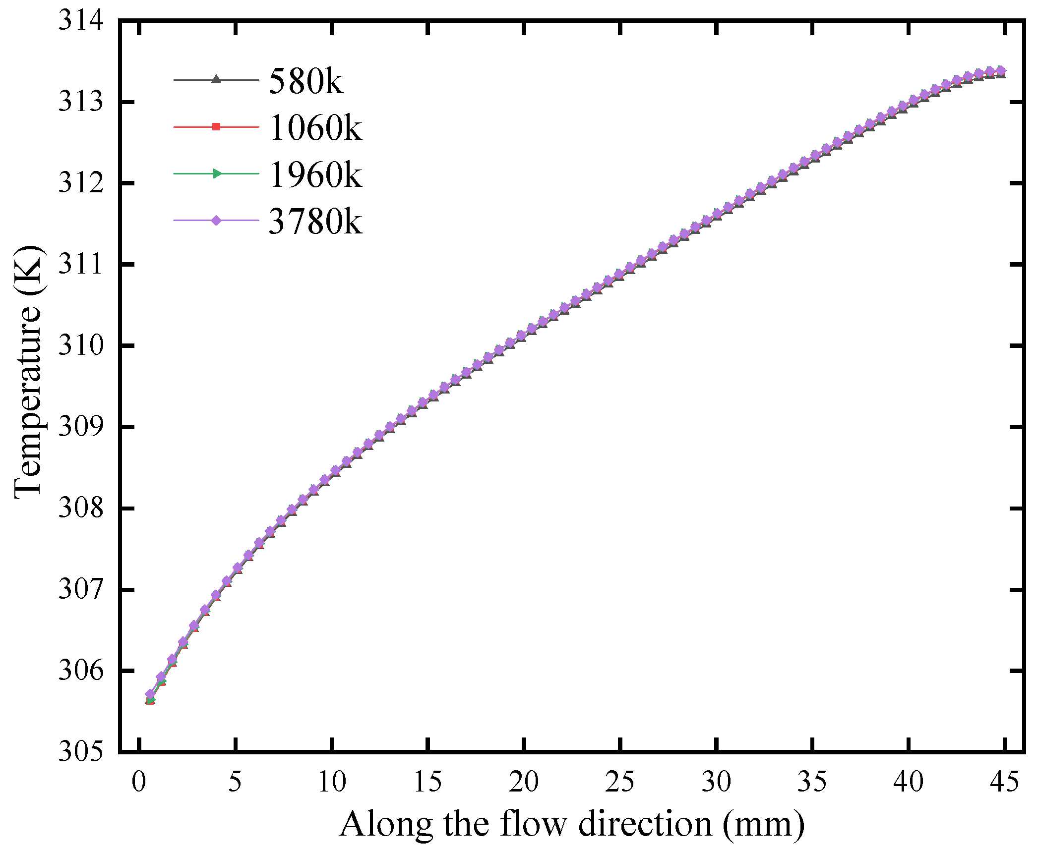
The computing domain is divided into three independent regions involving nanofluid, solid walls and the cover plate. The hexahedral mesh is generated Using ANSYS ICEM 2021. For Case 0, four different numbers of grids (580 k, 1060 k, 1960 k and 3780 k) are used in the grid independence test. The temperature variation curves by using four different numbers of grids which are shown along the bottom centerline in Figure 2. The difference of the results calculated by the latter three grids is less than 1%, so 1060 k grid numbers are selected for calculation.
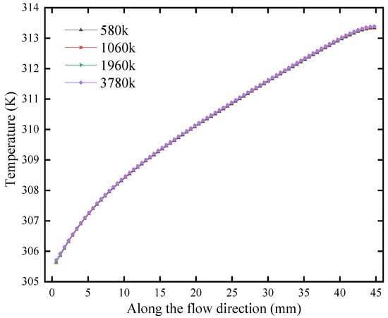
Figure 2.
Simulation results using different number of grids.
2.5.2. Model Validation
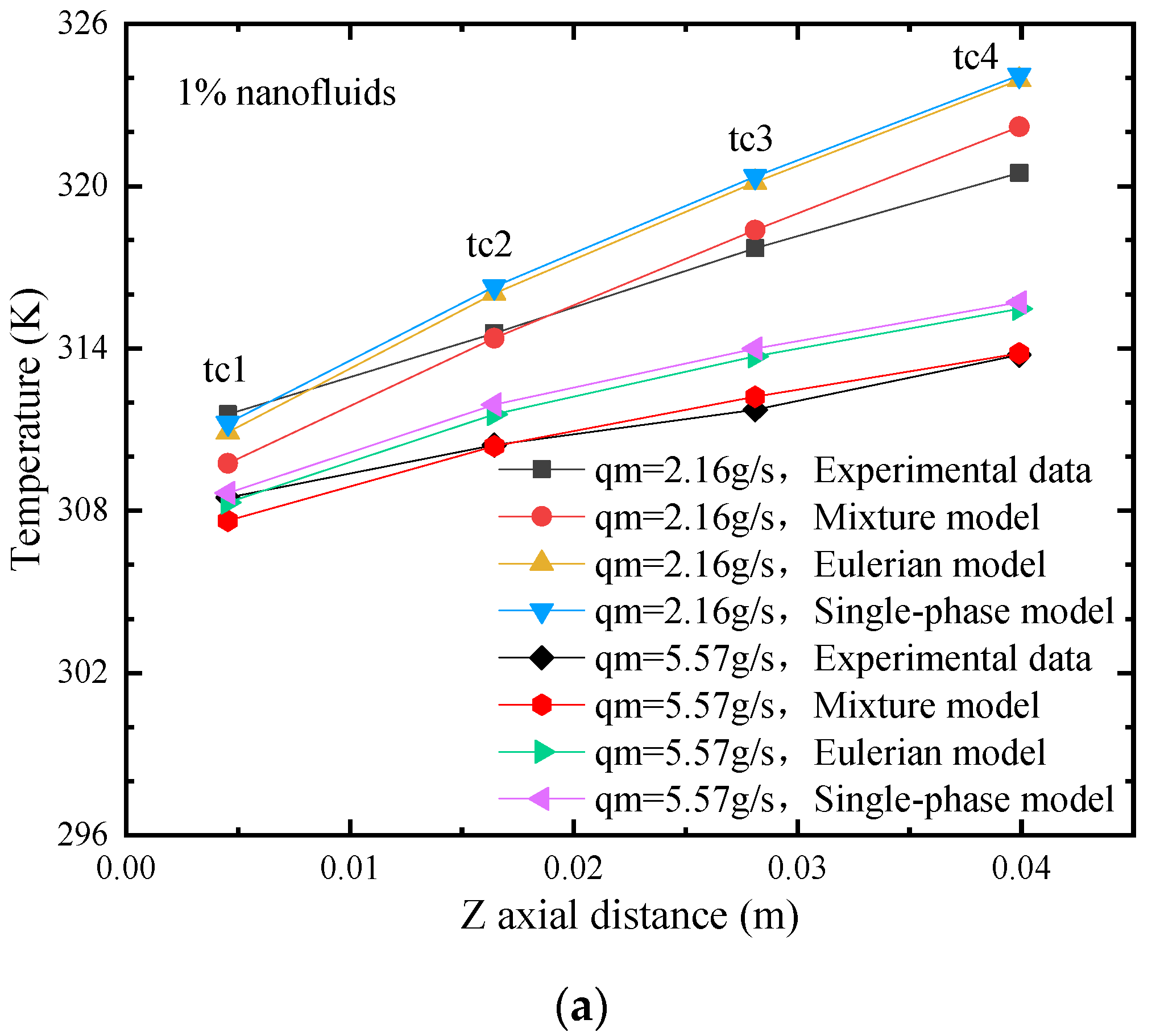
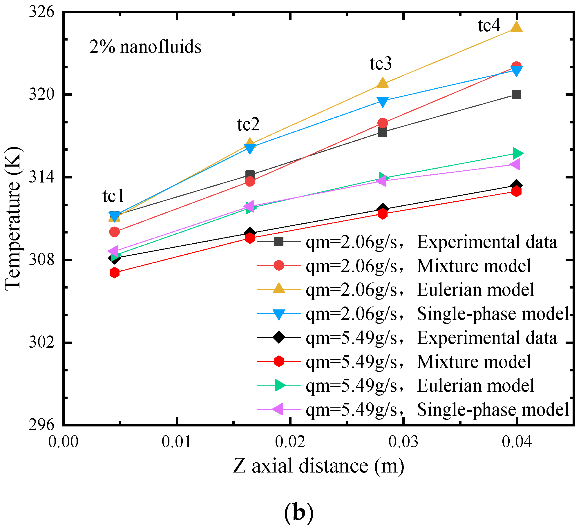
The numerical method is verified by comparing it to the experiment in the literature [33]. Figure 3 gives the results of SMC0 using Al2O3 nanofluids with different volume fractions. Three different models were used for comparison. The results show that compared to the other models, the results from the mixture model agree better with the experiment, which exhibits higher accuracy as the mass flow rate increases. The average error between using the mixture model and the experiment is only 0.35 K for 1% fraction, when the mass flow rate is 5.57 g/s. Similarly, for the mass flow rate of 5.49 g/s and a volume fraction of 2%, the average error is 0.54K. The mixture model takes into account the interfacial transfer characteristics as well as the diffusion and pulsation effects between the two phases, which contributes to the better accuracy.
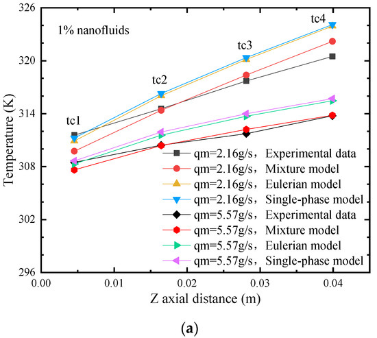
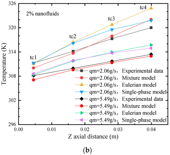
Figure 3.
Simulated and experimentally measured wall temperature along the flow direction with different mass flow rates. (a) 1% volume fraction. (b) 2% volume fraction.
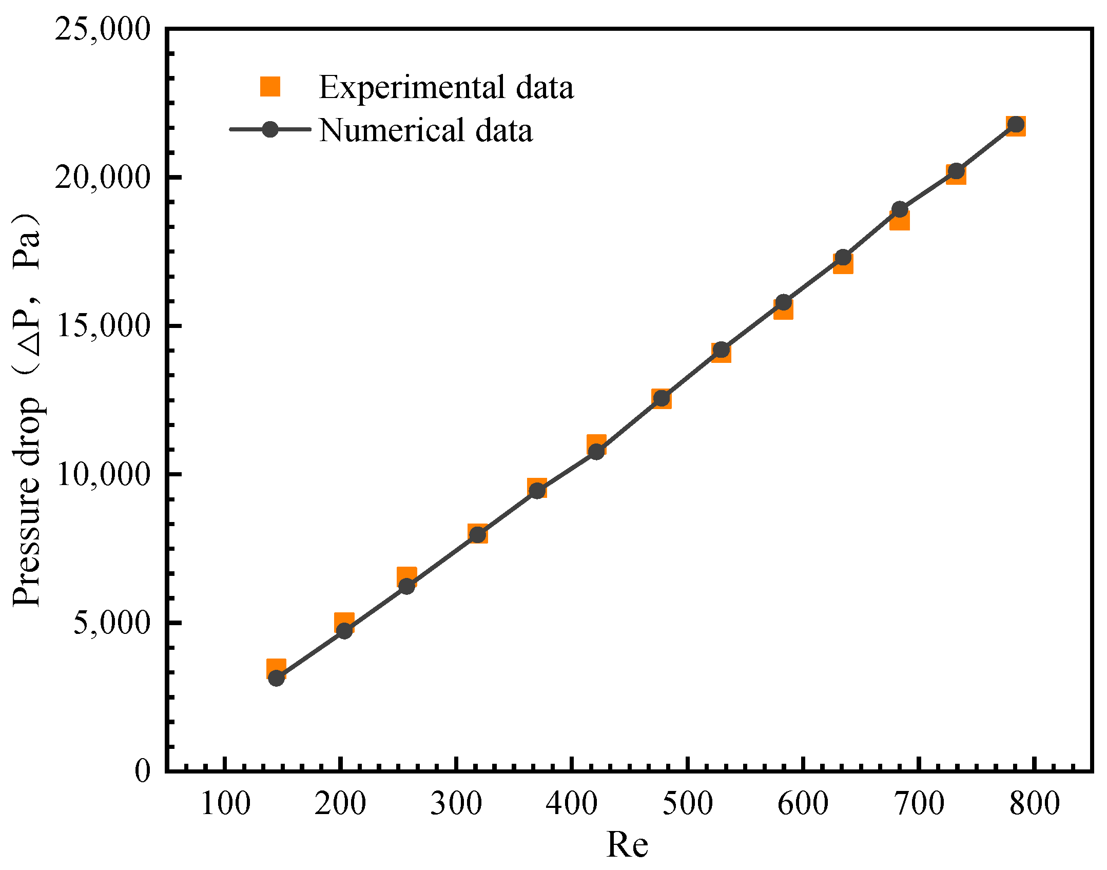
Figure 4 shows the pressure drop predicted by the mixture model for the volume fraction of 2%. Comparing the experimental and numerical results, it can be found that the maximum error is only 2.03%. Therefore, the flow characteristics simulated based on mixture model also agree very well with the experiments.

Figure 4.
Comparison of pressure drop between simulation and experiment by Lee et al. [33].
2.5.3. Study Cases
Based on the mixture model, the proposed rectangular grooved microchannel (RGMC) is compared with the smooth microchannel (SMC). The geometric parameters are given in Table 1. Pure water and Al2O3/water nanofluids with different volume fraction are considered to investigate the thermal performance of nanofluids both in SMC and RGMC. Additionally, different wall conditions will make turbulence characteristics sensitive to flow velocity; thus, the range of inlet velocity is set to 0.25–1.5 m/s, of which the corresponding range of the Reynolds number is about 150–750. Table 3 summarizes the variable range settings.
Table 3.
Range of variables in the study cases.
3. Results and Analysis
3.1. Heat Transfer Characteristics Analysis
In practical application, the most concerned indicator evaluating the thermal state of electronic device is the surface maximum temperature (Tmax). Correspondingly for the microchannel heat sink, Tmax occurs at the bottom surface.
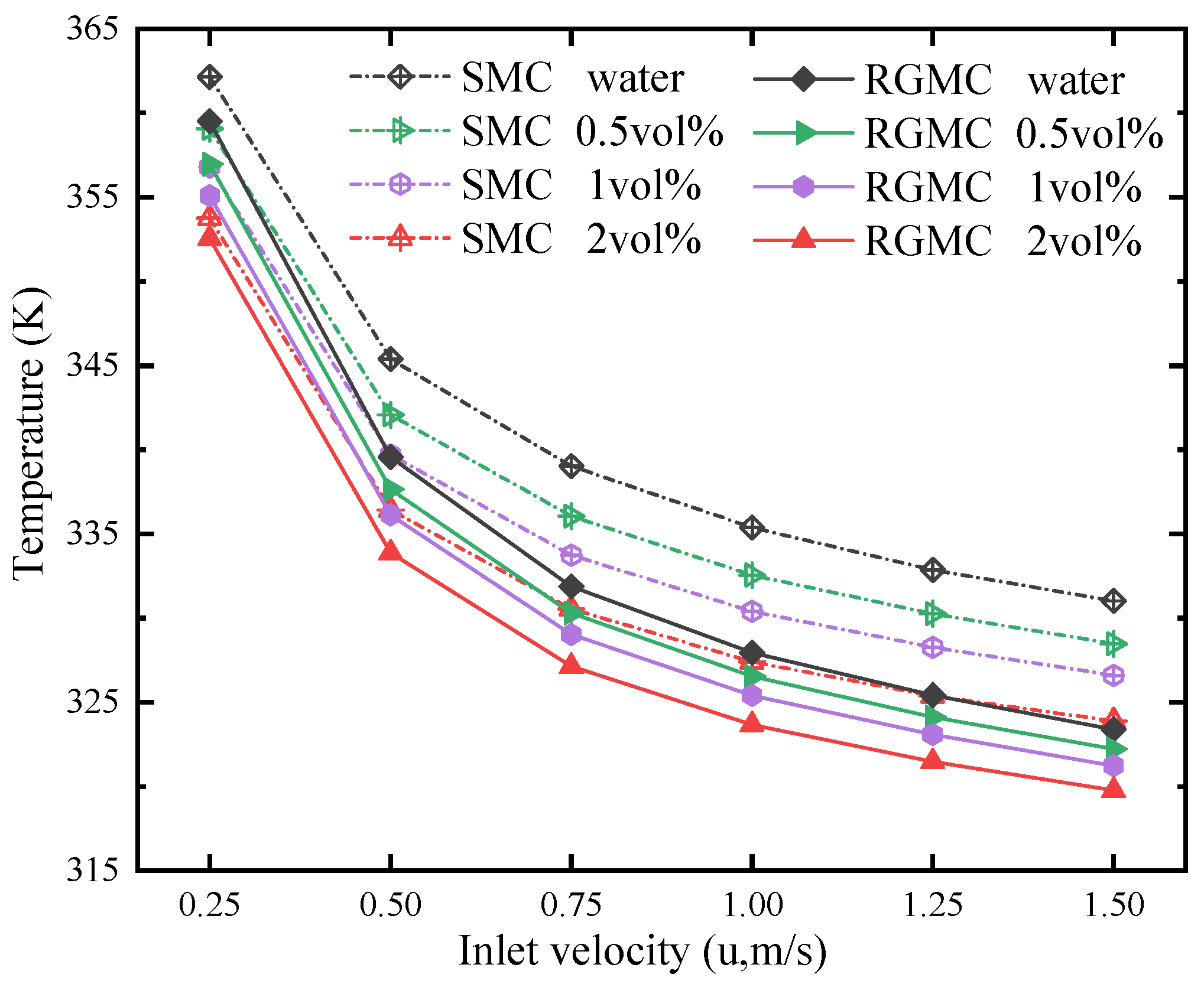
As shown in Figure 5, the maximum temperature (Tmax) of RGMC is significantly lower compared with that of SMC, between which the maximum difference is 7.64 K when both use water at 1.5 m/s. These effects become more significant at higher inlet velocity. Compared to the conventional SMC with water, RGMC with water reduces the maximum temperature from 332 K down to 323 K, while a combination of using 2 vol% Al2O3/water nanofluid in RGMC further reduces it down to 320 K at 1.5 m/s, which is considerable. Besides, at inlet velocity of 1.5 m/s, Tmax for RGMC is 5 K lower than SMC with 2 vol% Al2O3/water nanofluid. On one hand, the thermal conductivity of nanofluid is higher than that of pure water. On the other hand, disturbance occurs due to the grooves, which enhances the mixing of hot and cold fluid.
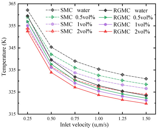
Figure 5.
Tmax variation at different inlet velocities and volume fractions.
Figure 6 shows temperature contours inside microchannels. In the fluid domain, which is the dark gray part, two planes (the blue part) are taken as shown in Figure 6a. Plane 1 is a vertical sectional plane at Z = 0.0095 m and Plane 2 is a horizontal sectional plane at Y = 0.00081 m. All contours are captured on the two planes. The temperature contours in Figure 6b are captured over Plane 1 of RGMC at 0.25 m/s under different volume fractions. For the case of pure water, the maximum temperature difference of the fluid is about 27.9 K. Comparatively, it is reduced to 18 K by using 2 vol% nanofluid. The results show that the uniformity of fluid temperature distribution in the microchannel becomes better with the increase in the nanofluid volume fraction. This is attributed to the higher thermal conductivity of nanofluids with higher volume fraction, which improves the heat transfer through the thermal boundary layers. The comparative temperature distributions on Plane 2 for the case at 1.25 m/s and the volume fraction of 0.5% are shown in Figure 6c. Compared with SMC, the fluid temperature near the wall of RGMC is significantly reduced from 326.3 K to 321.2 K. The asymmetric temperature distribution is due to the arrangement of rectangular grooves. Thus, the rectangular grooves can further improve convective heat transfer performance.
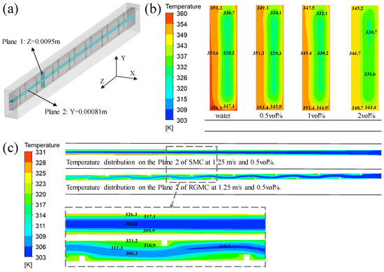
Figure 6.
(a) Two planes in the microchannel fluid domain. (b) The temperature distribution on the Plane 1 of RGMC at 0.25 m/s with different volume fractions. (c) The temperature distribution on the Plane 2 of different microchannel at 1.25 m/s with volume fraction 0.5%.
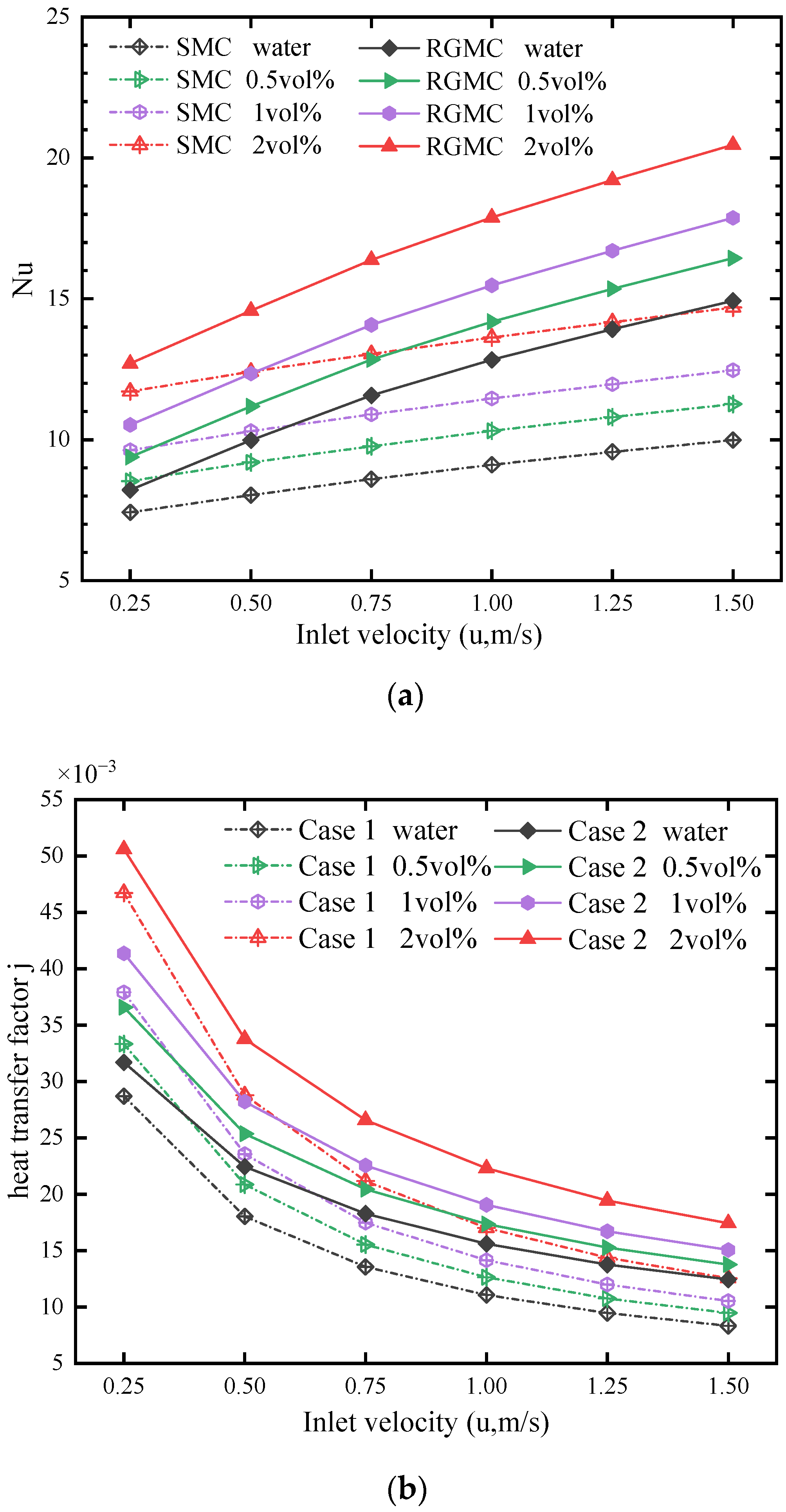
To evaluate the overall thermal performance, the Nusselt number and heat transfer factor are further discussed. The heat transfer factor is described by [42]:
Figure 7a gives the relation of the average Nusselt number with volume fractions of nanofluids at different inlet velocities. It shows that the average Nusselt number increases with the volume fraction, which indicates that using nanofluids improves thermal performance. The average Nusselt number of the grooved microchannel is much higher than that of the smooth one. With increasing inlet velocity, the difference of the Nusselt number between SMC and RGMC increases. At 1.5 m/s, the Nu of SMC with pure water is 10, while that of using 2 vol% nanofluid is 14.8, which increases by 48% compared to the former. Meanwhile, Nu of RGMC with pure water is 15, which is very close to that of SMC with 2 vol% nanofluid. Comparatively, Nu of RGMC with 2 vol% nanofluid is 20.5, which is 38.5% larger than that of SMC with the same nanofluid, and 36.7% larger than that of RGMC with pure water. This means combining RGMC and nanofluid enhances thermal performance considerably more than using any single one of them, which further indicates that the enhancement is comparable to increasing fluid thermal conductivity and disturbance. Figure 7b shows that the heat transfer factor of both the SMC and RGMC decreases with velocity. Increasing the volume fraction of nanofluid increases the heat transfer factor, which is more obvious at lower inlet velocity. At 0.25 m/s, j of SMC with pure water is about 28 × 10−3, while that using 2 vol% nanofluid is 47 × 10−3, which is 67.8% larger than the former. At higher inlet velocity, using RGMC increases j more obviously. At 1.5 m/s, j of SMC with 2 vol% nanofluid is 12.6, while that of RGMC with the same nanofluid is 17.5, which is about 39% larger than the former. This is because at lower inlet velocity, the fluid conductivity determines the thermal performance more than fluid disturbance. At higher inlet velocity, the fluid disturbance is enhanced, which becomes dominant and improves heat transfer.
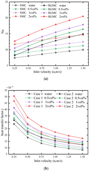
Figure 7.
Heat transfer properties of two microchannels with different volume fraction nanofluid and inlet velocity. (a) Average Nusselt number. (b) The heat transfer factor j.
3.2. Effect of Grooves on Flow Disturbance
The enhanced flow disturbance caused by the rectangular grooves of RGMC is the main cause of the heat transfer enhancement. Figure 8 shows streamline (b) and velocity (c) distribution of the two microchannels in the X-Z Plane (Y = 0.00081 m) at volume fraction 1%. As seen in Figure 8b, the streamlines of SMC are almost parallel to the channel wall in the laminar flow regime, which means the radial heat transfer depends only on the heat conduction of nanofluid. Comparatively, the rectangular grooves of RGMC promote the disturbance near the wall, which interrupts the flow boundary layer and develops second flow. These can significantly thin the thermal boundary layer and enhance the radial convection. As shown in Figure 8c, the velocity of SMC is symmetrically distributed along the center line, while the maximum velocity of RGMC is close to the component of the channel wall without grooves. As the inlet velocity increases, the maximum velocity difference along radial of RGMC becomes much larger than that of SMC. For example, at inlet velocity of 1.5 m/s, the maximum velocity difference for SMC reaches 2.1 m/s, while that of RGMC reaches 3.1 m/s. The stagnation zone is observed near the grooves, which extends with the increasing inlet velocity.
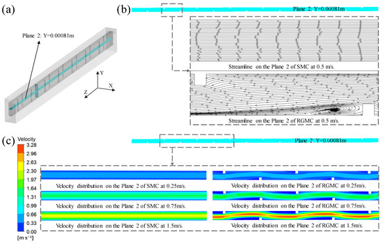
Figure 8.
The streamline and velocity distribution of two microchannels with volume fraction 1%. (a) Two planes in the microchannel fluid domain. (b) The streamline on the Plane 2 of two microchannels. (c) The velocity distribution on the Plane 2 of two microchannels.
3.3. Integrated Effect of Rectangular Groove on Temperature and Flow Fields
Due to the complex disturbance phenomenon of nanofluid in the microchannel with rectangular grooves, the field synergy theory is used to analyze the mechanism. There are several synergy indicators used to evaluate field synergy characteristics. Therein, the heat transfer performance is analyzed using the following equation.
where β is the synergy angle between the local velocity and the temperature gradient. Smaller β indicates the better synergistic relationship between the flow and heat transfer.
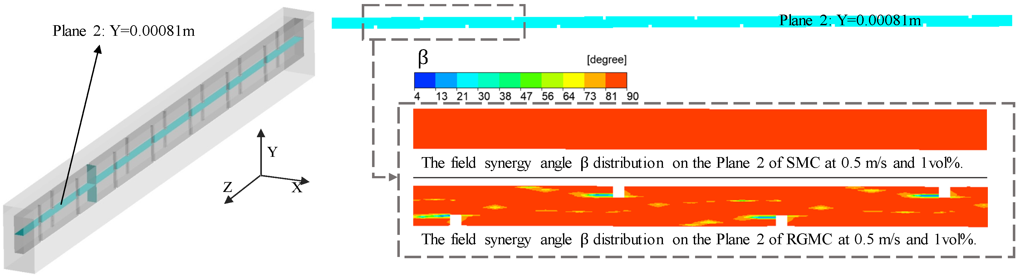
Figure 9 shows the distribution of β values on Plane 2 of SMC and RGMC. For SMC, the β values are around 85, while for the RGMC, the β values near the groove region are significantly reduced to around 40, even to below 10. This indicates better convective heat transfer performance. As seen in Figure 8b,c, this decrease in synergy angle of heat transfer β and enhancement in heat transfer is due to the disturbance near the groove. Moreover, the region near the center line also shows a lower β around 40–50, indicating the influence of the groove on the main flow except in the boundary layer region.

Figure 9.
Distribution of field synergy angles .
In addition, the average field synergy angle βα of fluid is calculated to evaluate the synergic effect between flow and heat transfer by the following formula:
where is the field synergy angle of any piece of area element, Vi is the volume of each discrete region.
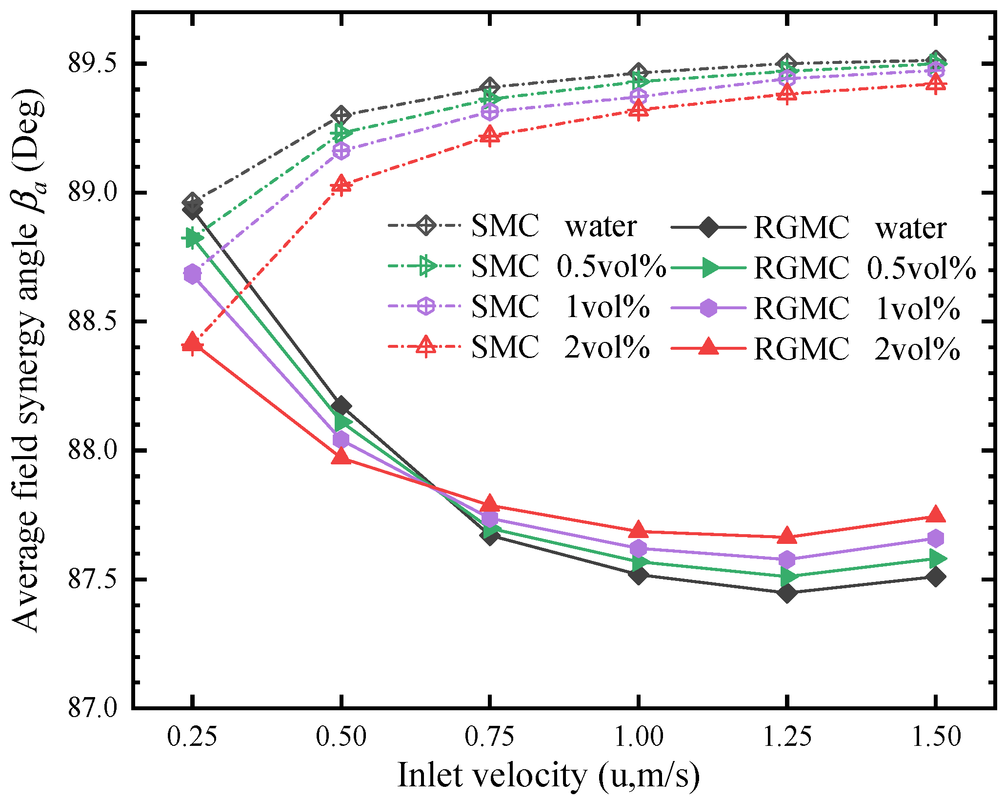
Figure 10 shows the variation of βα with inlet velocity under different volume fractions both of SMC and RGMC. Smaller βα represents better synergy between fluid flow and heat transfer, which enhances thermal performance. βα of RGMC are obviously smaller than those of SMC under all the conditions, except for at the lowest inlet velocity 0.25 m/s, where βα are very close between SMC and RGMC, with values from 88.4 to 89 Deg. The difference of βα between SMC and RGMC generally increases with the inlet velocity. At 1.5 m/s, βα of SMC with pure water is 89.6 Deg, while that of RGMC with pure water 87.5 Deg, which is 2.1 Deg lower than the former, and βα of SMC with 2 vol% nanofluid is 89.4 Deg, which is 1.66 Deg higher than the βα value of 87.74 Deg for RGMC. This indicates the RGMC has a much greater influence on the synergy effect at higher inlet velocity. The reason is that the higher inlet velocity results to higher non-uniformity of velocity, as shown in Figure 8c, which enhances the synergy effect. Meanwhile, increasing the volume fraction of nanofluid decreases βα more obviously at lower inlet velocity. At 0.25 m/s, βα of SMC with pure water is 88.95 Deg, while that with 2 vol% nanofluid is 88.4 Deg, which is 0.55 Deg lower than the former. The trends of βα are very consistent with the thermal performance discussed previously, which indicates the improvement in synergy between fluid flow and heat transfer attributes to the enhanced thermal performance. Increasing the volume fraction of nanofluid improves the synergic effect mainly at lower inlet velocity, while at higher inlet velocity, using grooves to make fluid disturbance improves the synergic effect more significantly.
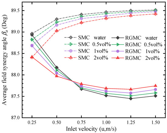
Figure 10.
Variation of the average heat transfer field synergy angle βα.
3.4. Flow Characteristics Analysis
The improved thermal performance of the microchannel is usually at the expense of higher pressure drop, which requires more pumping power. To evaluate the flow performance of the grooved microchannel heat sink using nano-fluids as coolant, the Darcy friction factor f is analyzed, which is defined as:
where Dh is the hydraulic diameter, u is the inlet velocity and L is the channel length.
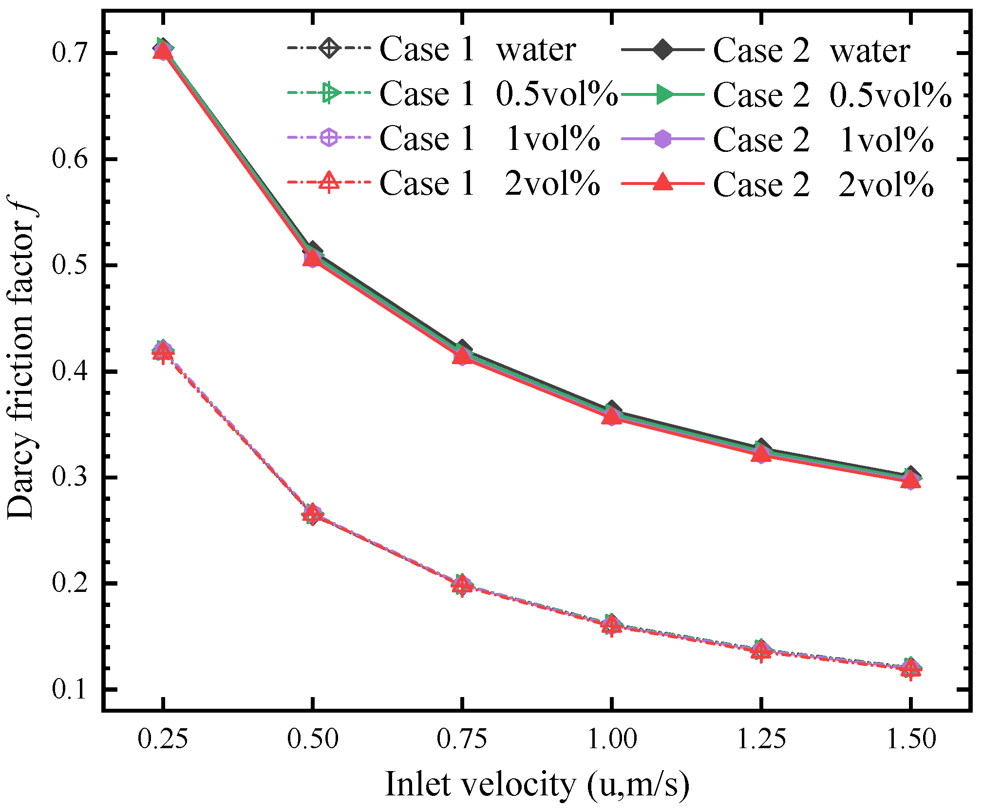
Figure 11 shows the comparison of f between the SMC and RGMC under different volume fractions. It is found that f of RGMC is always about 0.3 larger than that of SMC as the inlet velocity increases, while the influence of the volume fraction negligible.
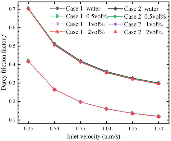
Figure 11.
Darcy friction factor f at different inlet velocities and volume fractions.
4. Conclusions
In the view of enhancing heat transfer of microchannel heat sink, the combining effect between using nanofluid and groove structure is researched. Accordingly, this study proposes a novel rectangular grooved microchannel (RGMC) with Al2O3/water nanofluid as the coolant. The thermal performance of the proposed microchannel is investigated using the numerical method and compared with a conventional smooth microchannel (SMC). Following analysis of the heat transfer characteristics, the main conclusions are as follows:
- The thermal performance is significantly improved by combining nanofluid and grooves rather than using only one of them. At 1.5 m/s, Nu of RGMC with 2 vol% nanofluid is 20.5, which 38.5% larger than that of SMC with the same nanofluid, and 36.7% larger than that of RGMC with pure water. Analyzing the heat transfer factor further shows that nanofluid enhances heat transfer more significantly at lower inlet velocity, while grooves enhance heat transfer more significantly at higher inlet velocity.
- Compared to SMC, the enhanced disturbance in RGMC can thin the thermal boundary layer and enhance the radial convection. The disturbance leads to more obvious flow irregularity. At 1.5 m/s, the maximum velocity difference of SMC is 2.1 m/s, while that of RGMC is 3.1 m/s, which is about 47.6% larger than the former.
- The synergy angle β near the center line of RGMC is much lower than that of SMC, which represents better thermal performance. At 1.5 m/s, the average field synergy angle βα of RGMC with pure water is 2.1 Deg lower than that of SMC. At 0.25 m/s, βα of SMC with 2 vol% nanofluid is 0.55 Deg lower than that using pure water. Increasing volume fraction of nanofluid improves the synergic effect mainly at lower inlet velocity, while at higher inlet velocity, using grooves to make fluid disturbance improves the synergic effect more significantly.
- The flow resistance can be increased by using the rectangular grooves. It is found that friction factor f of RGMC is always about 0.3 larger than that of SMC.
The results and conclusions obtained in this study will provide useful guidance for improving the thermal performance of the microchannel heat exchanger, which has been widely used in building cooling systems.
Author Contributions
Conceptualization, N.M. and X.Z.; methodology, X.Z. and H.Y.; formal analysis, X.Z. and H.Y.; investigation, X.Z.; writing—original draft preparation, X.Z.; writing—review and editing, N.M. and T.H.; supervision, T.H. and N.M.; project administration, N.M.; funding acquisition, N.M. All authors have read and agreed to the published version of the manuscript.
Funding
This research was funded by National Natural Science Foundation of China (NSFC Grant No. 52276092), Grant-in-Aid for JSPS Fellows (21F20056) and Shandong Provincial Natural Science Foundation, China (No. ZR2020ME170).
Data Availability Statement
Not applicable.
Conflicts of Interest
The authors declare no conflict of interest.
Nomenclature
| a | Acceleration, m/s2 |
| Cp | Specific heat capacity, J/(kg·K) |
| d | Diameter, μm |
| D | Hydraulic diameter, μm |
| E | Depth of rectangular groove, μm |
| Fc | Field synergy number |
| g | Gravitational acceleration, m/s2 |
| H | Height of microchannel, μm |
| j | Heat transfer factor |
| Knf | Knudsen number |
| L | Length of microchannel heat sink, mm |
| Nu | Nusselt number |
| p | Pressure, Pa |
| Pr | Prandtl number |
| q | Heat flux, W/cm2 |
| Re | Reynolds number |
| T | Temperature, K |
| u | Inlet velocity, m/s |
| V | Velocity, m/s; Control volume, m3, used in FEM |
| W | Width of microchannel, μm |
| α | Field synergy angle between velocity vector and velocity gradient |
| β | Field synergy angle between velocity vector and temperature gradient |
| δ | Thermal boundary layer thickness, μm |
| φ | Nano particle concentration |
| ρ | Mass density of fluid, kg/m3 |
| µ | Kinematic viscosity, Pa·s |
| Subscripts | |
| Bf | Base fluid |
| Dr | Drift |
| F | Fluid domain |
| In | Inlet |
| K | Summation index |
| M | Mass-averaged |
| Max | Maximal value |
| Nf | Nanofluid |
| Out | Outlet |
| P | Particle |
| Pf | Nanoparticle relative to base fluid |
| S | Solid domain |
| T | Thermal |
| x, y, z | Cartesian coordinates |
| 0, 1, 2 | Case number |
References
- Kandlikar, S.G. High Flux Heat Removal with Microchannels—A Roadmap of Challenges and Opportunities. Heat Transf. Eng. 2005, 26, 5–14. [Google Scholar] [CrossRef]
- Tuckerman, D.B.; Pease, R.F.W. High-Performance Heat Sinking for VLSI. IEEE Electron Device Lett. 1981, 2, 126–129. [Google Scholar] [CrossRef]
- Guo, Z.Y.; Li, Z.X. Size Effect on Single-Phase Channel Flow and Heat Transfer at Microscale. Int. J. Heat Fluid Flow 2003, 24, 284–298. [Google Scholar] [CrossRef]
- Gad-el-Hak, M. Comments on “Critical View on New Results in Micro-Fluid Mechanics”. Int. J. Heat Mass Transf. 2003, 46, 3941–3945. [Google Scholar] [CrossRef]
- Kim, D.K.; Kim, S.J. Averaging Approach for Microchannel Heat Sinks Subject to the Uniform Wall Temperature Condition. Int. J. Heat Mass Transf. 2006, 49, 695–706. [Google Scholar] [CrossRef]
- Lee, P.S.; Garimella, S.V.; Liu, D. Investigation of Heat Transfer in Rectangular Microchannels. Int. J. Heat Mass Transf. 2005, 48, 1688–1704. [Google Scholar] [CrossRef]
- Adams, T.M.; Dowling, M.F.; Abdel-Khalik, S.I.; Jeter, S.M. Applicability of Traditional Turbulent Single-Phase Forced Convection Correlations to Non-Circular Microchannels. Int. J. Heat Mass Transf. 1999, 42, 4411–4415. [Google Scholar] [CrossRef]
- Shang, X.; Li, Q.; Cao, Q.; Li, Z.; Shao, W.; Cui, Z. Mathematical Modeling and Multi-Objective Optimization on the Rectangular Micro-Channel Heat Sink. SSRN Electron. J. 2022, 184, 107926. [Google Scholar] [CrossRef]
- Choi, S.U.S. Enhancing Thermal Conductivity of Fluids with Nanoparticles. Am. Soc. Mech. Eng. Fluids Eng. Div. FED 1995, 231, 99–105. [Google Scholar]
- Alawi, O.A.; Sidik, N.A.C.; Xian, H.W.; Kean, T.H.; Kazi, S.N. Thermal Conductivity and Viscosity Models of Metallic Oxides Nanofluids. Int. J. Heat Mass Transf. 2018, 116, 1314–1325. [Google Scholar] [CrossRef]
- Thansekhar, M.R.; Anbumeenakshi, C. Experimental Investigation of Thermal Performance of Microchannel Heat Sink with Nanofluids Al2O3/Water and SiO2/Water. Exp. Tech. 2017, 41, 399–406. [Google Scholar] [CrossRef]
- Li, C.; Huang, J.; Shang, Y.; Huang, H. Study on the Flow and Heat Dissipation of Water-Based Alumina Nanofluids in Microchannels. Case Stud. Therm. Eng. 2020, 22, 100746. [Google Scholar] [CrossRef]
- Nguyen, C.T.; Roy, G.; Gauthier, C.; Galanis, N. Heat Transfer Enhancement Using Al2O3-Water Nanofluid for an Electronic Liquid Cooling System. Appl. Therm. Eng. 2007, 27, 1501–1506. [Google Scholar] [CrossRef]
- Varun Kumar, R.S.; Alhadhrami, A.; Punith Gowda, R.J.; Naveen Kumar, R.; Prasannakumara, B.C. Exploration of Arrhenius Activation Energy on Hybrid Nanofluid Flow over a Curved Stretchable Surface. ZAMM Z. Angew. Math. Mech. 2021, 101, 1–14. [Google Scholar] [CrossRef]
- Punith Gowda, R.J.; Naveen Kumar, R.; Jyothi, A.M.; Prasannakumara, B.C.; Sarris, I.E. Impact of Binary Chemical Reaction and Activation Energy on Heat and Mass Transfer of Marangoni Driven Boundary Layer Flow of a Non-Newtonian Nanofluid. Processes 2021, 9, 702. [Google Scholar] [CrossRef]
- Gowda, R.J.P.; Kumar, R.N.; Rauf, A.; Prasannakumara, B.C.; Shehzad, S.A. Magnetized Flow of Sutterby Nanofluid through Cattaneo-Christov Theory of Heat Diffusion and Stefan Blowing Condition. Appl. Nanosci. 2021. [Google Scholar] [CrossRef]
- Kumar, R.S.V.; Gowda, R.J.P.; Kumar, R.N.; Radhika, M.; Prasannakumara, B.C. Two-phase flow of dusty fluid with suspended hybrid nanoparticles over a stretching cylinder with modified Fourier heat flux. SN Appl. Sci. 2021, 3, 384. [Google Scholar]
- Punith Gowda, R.J.; Naveen Kumar, R.; Prasannakumara, B.C. Two-Phase Darcy-Forchheimer Flow of Dusty Hybrid Nanofluid with Viscous Dissipation Over a Cylinder. Int. J. Appl. Comput. Math. 2021, 7, 1–18. [Google Scholar] [CrossRef]
- Heris, S.Z.; Esfahany, M.N.; Etemad, G. Numerical Investigation of Nanofluid Laminar Convective Heat Transfer through a Circular Tube. Numer. Heat Transf. Part A Appl. 2007, 52, 1043–1058. [Google Scholar] [CrossRef]
- Akbari, M.; Galanis, N.; Behzadmehr, A. Comparative Analysis of Single and Two-Phase Models for CFD Studies of Nanofluid Heat Transfer. Int. J. Therm. Sci. 2011, 50, 1343–1354. [Google Scholar] [CrossRef]
- Haghshenas Fard, M.; Esfahany, M.N.; Talaie, M.R. Numerical Study of Convective Heat Transfer of Nanofluids in a Circular Tube Two-Phase Model versus Single-Phase Model. Int. Commun. Heat Mass Transf. 2010, 37, 91–97. [Google Scholar] [CrossRef]
- Moraveji, M.K.; Ardehali, R.M. CFD Modeling (Comparing Single and Two-Phase Approaches) on Thermal Performance of Al2o3/Water Nanofluid in Mini-Channel Heat Sink. Int. Commun. Heat Mass Transf. 2013, 44, 157–164. [Google Scholar] [CrossRef]
- Kumar, R.N.; Gowda, R.J.P.; Alam, M.M.; Ahmad, I.; Mahrous, Y.M.; Gorji, M.R.; Prasannakumara, B.C. Inspection of Convective Heat Transfer and KKL Correlation for Simulation of Nanofluid Flow over a Curved Stretching Sheet. Int. Commun. Heat Mass Transf. 2021, 126, 105445. [Google Scholar] [CrossRef]
- Naveen Kumar, R.; Suresha, S.; Gowda, R.J.P.; Megalamani, S.B.; Prasannakumara, B.C. Exploring the Impact of Magnetic Dipole on the Radiative Nanofluid Flow over a Stretching Sheet by Means of KKL Model. Pramana-J. Phys. 2021, 95. [Google Scholar] [CrossRef]
- Xia, G.D.; Jiang, J.; Wang, J.; Zhai, Y.L.; Ma, D.D. Effects of Different Geometric Structures on Fluid Flow and Heat Transfer Performance in Microchannel Heat Sinks. Int. J. Heat Mass Transf. 2015, 80, 439–447. [Google Scholar] [CrossRef]
- Li, F.; Zhu, W.; He, H. Field Synergy Analysis on Flow and Heat Transfer Characteristics of Nanofluid in Microchannel with Non-Uniform Cavities Configuration. Int. J. Heat Mass Transf. 2019, 144, 118617. [Google Scholar] [CrossRef]
- Chen, Z.; Feng, Z.; Zhang, Q.; Zhang, J.; Guo, F. Effects of Regular Triangular Prisms on Thermal and Hydraulic Characteristics in a Minichannel Heat Sink. Int. J. Heat Mass Transf. 2022, 188, 122583. [Google Scholar] [CrossRef]
- Naqiuddin, N.H.; Saw, L.H.; Yew, M.C.; Yusof, F.; Poon, H.M.; Cai, Z.; Thiam, H.S. Numerical Investigation for Optimizing Segmented Micro-Channel Heat Sink by Taguchi-Grey Method. Appl. Energy 2018, 222, 437–450. [Google Scholar] [CrossRef]
- Chai, L.; Xia, G.D.; Wang, H.S. Numerical Study of Laminar Flow and Heat Transfer in Microchannel Heat Sink with Offset Ribs on Sidewalls. Appl. Therm. Eng. 2016, 92, 32–41. [Google Scholar] [CrossRef]
- Hong, F.; Cheng, P. Three Dimensional Numerical Analyses and Optimization of Offset Strip-Fin Microchannel Heat Sinks. Int. Commun. Heat Mass Transf. 2009, 36, 651–656. [Google Scholar] [CrossRef]
- Promvonge, P.; Sripattanapipat, S.; Kwankaomeng, S. Laminar Periodic Flow and Heat Transfer in Square Channel with 45° Inline Baffles on Two Opposite Walls. Int. J. Therm. Sci. 2010, 49, 963–975. [Google Scholar] [CrossRef]
- Xie, X.L.; Tao, W.Q.; He, Y.L. Numerical Study of Turbulent Heat Transfer and Pressure Drop Characteristics in a Water-Cooled Minichannel Heat Sink. J. Electron. Packag. Trans. ASME 2007, 129, 247–255. [Google Scholar] [CrossRef]
- Lee, J.; Mudawar, I. Assessment of the Effectiveness of Nanofluids for Single-Phase and Two-Phase Heat Transfer in Micro-Channels. Int. J. Heat Mass Transf. 2007, 50, 452–463. [Google Scholar] [CrossRef]
- Mokhtari Moghari, R.; Akbarinia, A.; Shariat, M.; Talebi, F.; Laur, R. Two Phase Mixed Convection Al2O3-Water Nanofluid Flow in an Annulus. Int. J. Multiph. Flow 2011, 37, 585–595. [Google Scholar] [CrossRef]
- Shi, X.; Li, S.; Wei, Y.; Gao, J. Numerical Investigation of Laminar Convective Heat Transfer and Pressure Drop of Water-Based Al2O3 Nanofluids in a Microchannel. Int. Commun. Heat Mass Transf. 2018, 90, 111–120. [Google Scholar] [CrossRef]
- Zhao, J.J.; Duan, Y.Y.; Wang, X.D.; Wang, B.X. Effect of Nanofluids on Thin Film Evaporation in Microchannels. J. Nanoparticle Res. 2011, 13, 5033–5047. [Google Scholar] [CrossRef]
- Koo, J.; Kleinstreuer, C. A New Thermal Conductivity Model for Nanofluids. J. Nanoparticle Res. 2004, 6, 577–588. [Google Scholar] [CrossRef]
- Chon, C.H.; Kihm, K.D.; Lee, S.P.; Choi, S.U.S. Empirical Correlation Finding the Role of Temperature and Particle Size for Nanofluid (Al2O3) Thermal Conductivity Enhancement. Appl. Phys. Lett. 2005, 87, 1–3. [Google Scholar] [CrossRef]
- Jiang, F.; Sousa, A.C.M. Effective Thermal Conductivity of Heterogeneous Multi-Component Materials: An SPH Implementation. Heat Mass Transf. Stoffuebertragung 2007, 43, 479–491. [Google Scholar] [CrossRef]
- Lisy, V.; Tothova, J. On the (Hydrodynamic) Memory in the Theory of Brownian Motion. arXiv 2004, arXiv:cond-mat/0410222. [Google Scholar]
- Yu, H.; Zhuang, J.; Li, T.; Li, W.; He, T.; Mao, N. Influence of Transient Heat Flux on Boiling Flow Pattern in a Straight Microchannel Applied in Concentrator Photovoltaic Systems. Int. J. Heat Mass Transf. 2022, 190, 122792. [Google Scholar] [CrossRef]
- Sekulic, D.P. Compact Heat Exchangers. In Handbook of Thermal Science and Engineering; Springer: Cham, Switzerland, 2017. [Google Scholar] [CrossRef]


Publisher’s Note: MDPI stays neutral with regard to jurisdictional claims in published maps and institutional affiliations. |
© 2022 by the authors. Licensee MDPI, Basel, Switzerland. This article is an open access article distributed under the terms and conditions of the Creative Commons Attribution (CC BY) license (https://creativecommons.org/licenses/by/4.0/).