Article

Dual Three-Phase Permanent Magnet Synchronous Machines Vector Control Based on Triple Rotating Reference Frame

1
The Sixty-Third Research Institute, National University of Defense Technology, Nanjing 210007, China
2
College of Automation Engineering, Nanjing University of Aeronautics and Astronautics, Nanjing 211106, China
*
Author to whom correspondence should be addressed.
Energies 2022, 15(19), 7286; https://doi.org/10.3390/en15197286
Submission received: 30 July 2022 / Revised: 22 September 2022 / Accepted: 23 September 2022 / Published: 4 October 2022
(This article belongs to the Special Issue Advanced Permanent Magnet Machines and Drives)

Abstract

:
This paper presents a triple rotating coordinate transformed vector control method for dual three-phase permanent magnet (PM) machines. In the proposed scheme, the control variables are converted to three sets of αβ components directly, which are 120° electric degrees different from each other. It omits the complicated six-dimensional transformed matrix and reduces the computation greatly. The relationship with vector space (VSD) control was mathematically analyzed. By ensuring the consistency of control variables in the three stationary reference frames, the suggested method can not only achieve the same fundamental control performance as VSD but compensate for the imbalance current caused by the harmonics in the back electromotive force. In addition, the proposed method belongs to multi redundancy control in theory, which is maybe a good solution for fault-tolerant operation. Finally, a prototype dual three-phase PM machine was tested. The experimental results are in good agreement with the theoretical analysis.

1. Introduction

The ability to penetrate seawater has long been a major problem in wireless communication [1]. Though low-frequency electromagnetic waves have great potentiality in the underwater covert communication field, the most widely studied low-frequency transmitting antenna belongs to electrically small antennas (ESA) with the features of bulky size, low radiation efficiency, high transmitting power, and energy consumption. It becomes an important bottleneck to the further development of low-frequency electromagnetic communication [2].
Mechanical Antenna (MA) was initially developed to achieve the miniaturization and low power consumption of low-frequency transmitting systems by the US Defense Advanced Research Projects Agency (DARPA) [3]. MA directly generates a strong static electric or magnetic field with the mechanical movement of special, exciting materials, eliminating the matching tuning network and its corresponding additional losses. It is expected to break through the physical scale limit of traditional low-frequency ESA [4]. Depending on different exciting materials and mechanical movement modes, MA can be broadly divided into four classes: vibrating-electret based MA (VEBMA), vibrating-magnet based MA (VMBMA), rotating-electret based MA (REBMA), and rotating-magnet based MA (RMBMA). Among them, RMBMA attracts domestic and foreign attention that benefits from the mature application of rare earth permanent magnetic materials and servo control [5,6,7]. Typical RMBMA architecture consists of a permanent spinning magnet and a rotating servo drive system, as shown in Figure 1. Obviously, the transmission characteristics of RMBMA are closely related to the performance of PMSM. For example, the transmission capacity will be proportional to Tem/J. Hence, increasing the output torque can improve MA efficiency.
Multiphase electric machines have numerous advantages over traditional three-phase machines, such as torque enhancement, high efficiency, and low torque ripple. They are obtained in wide applications; one of the most common multiphase machine structures is the dual three-phase machine [8,9,10]. It consists of two isolated three-phase winding sets shifted by 30° electric degrees. The special structure determines the diversity of its control methods. An effective control scheme is an essential part of dual three-phase PMSM drives, which are closely related to the performance and the whole application. However, control of dual three-phase PMSM is more challenging than other machines due to the coupling and asymmetry between two windings [11].
The vector space decomposition (VSD) method is the most widely used multiphase modeling and control approach [12,13]. However, the original VSD control suffers from imbalanced currents between two winding sets. Some improvements were suggested to solve imbalance currents [14,15]. While the solutions are overcomplicated, they have not achieved the desired effect in practice. Double d-q current control is another alternative approach for this particular winding type, which is capable of balancing currents. However, it is generally known that this alternative approach has the disadvantage of cross-coupling that induces current harmonics. Additionally, it was criticized for reducing winding utilization in fault-tolerant control [16,17,18,19].
The previous review of control strategies for dual three-phase PMSMs indicates that further improvements and better control solutions are needed for balance current, harmonic current suppression, simplicity, and high winding availability for fault-tolerant operation. Therefore, this paper aimed to develop a control scheme for dual three-phase PMSM based on a triple rotating reference frame. A simplified model to analyze the triple dq transformation was established. The comparison between VSD and triple dq transformation was analytically derived. The novelty of the proposed method was to perform the current control in a new reference frame, which solves the problems of balanced current sharing and current harmonics. It can also provide a practical means for improving the performance of dual three-phase PMSMs with redundant fault-tolerant control.

2. Mathematical Model of Dual Three-phase Machines Based on Triple Stationary Reference Frame

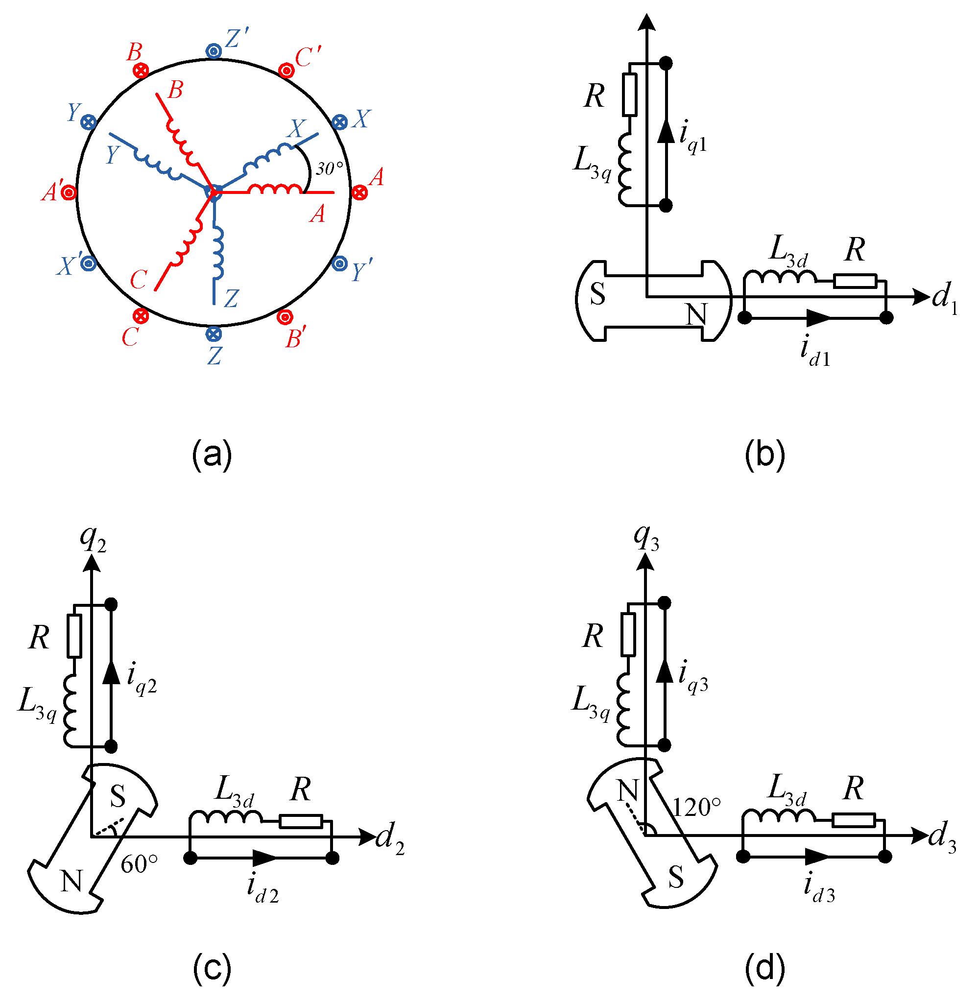
Due to the special structure, the dual three-phase machine can be regarded as three sets of orthogonal two-phase winding, i.e., A&Z, B&X, and C&Y, as shown in Figure 2a, even if with two isolated neutral points. Hence, the variables in the original six-dimensional system can be mapped into three virtual stationary coordinates, shifted 120° from each other. The three stationary coordinates are designated as α1-β1, α2-β2, and α3-β3.
The variables in each αβ frame can be converted to dq components directly by the modified Park transformation:
P 3 d q θ e = cos θ e sin θ e sin θ e cos θ e
Thus, the total transformation can be expressed as:
f d 1 f q 1 f d 2 f q 2 f d 3 f q 3 T = T 3 d q f A f B f C f X f Y f Z T
T 3 d q = P 3 d q θ 1 P 3 d q θ 2 P 3 d q θ 3
where θ1 = θe, θ2 = θe − 120°, and θ1 = θe + 120°; Symbol f is the machine variable, which can represent voltage, current, or flux.
The voltage, flux, and electrical torque equations in the original six-dimensional coordinate system can be mapped into a triple stationary reference frame by both sides multiplied T3dq. By simplifying and omitting higher harmonic inductance components, the voltage equations in the new reference frame can be rewritten as follows:
u d 1 = R i d 1 + ψ ˙ d 1 ω e ψ q 1 u q 1 = R i q 1 + ψ ˙ q 1 + ω e ψ d 1 u d 2 = R i d 2 + ψ ˙ d 2 ω e ψ q 2 u q 2 = R i q 2 + ψ ˙ q 2 + ω e ψ d 2 u d 3 = R i d 3 + ψ ˙ d 3 ω e ψ q 3 u q 3 = R i q 3 + ψ ˙ q 3 + ω e ψ d 3
Additionally, the flux equations:
ψ d 1 = L a a d + L a a l i d 1 + L a a d i d 2 + i d 3 + ψ f d ψ q 1 = L a a q + L a a l i q 1 + L a a q i q 2 + i q 3 ψ d 2 = L a a d + L a a l i d 2 + L a a d i d 1 + i d 3 + ψ f d ψ q 2 = L a a q + L a a l i q 2 + L a a q i q 1 + i q 3 ψ d 3 = L a a d + L a a l i d 3 + L a a d i d 1 + i d 2 + ψ f d ψ q 3 = L a a q + L a a l i q 3 + L a a q i q 1 + i q 2
Based on the electrical machinery theory with Virtual Displacement, the electromagnetic torque Te can be represented as the derivative of magnetic co-energy Wc with respect to mechanical position θm:
T e = W c θ m = p n 1 2 I s T L s θ e I s + I s T ψ s θ e
The electromagnetic torque in the new reference frame is obtained by substituting (3)–(5) into (6):
T e = p n L a a d L a a q ( i d 1 + i d 2 + i d 3 ) ( i q 1 + i q 2 + i q 3 ) + ψ f d ( i q 1 + i q 2 + i q 3 )
From the flux Equation (5), it can be seen that there are complex cross couplings among the three d-q reference frames. It is therefore desirable to thoroughly understand the variables in the new model by relating them with variables in the conventional double d-q model, which is able to interpret physically. This can easily be performed by comparing the transformation matrices between the two models.
The Clark–Park transformation of the conventional double d-q model is given as:
f D 1 f Q 1 T = T D Q 1 f A f B f C T f D 2 f Q 2 T = T D Q 2 f X f Y f Z T
With
T D Q 1 = 2 3 cos θ e sin θ e cos θ e 120 sin θ e 120 cos θ e + 120 sin θ e + 120 T
T D Q 2 = 2 3 cos θ e 30 sin θ e 30 cos θ e 150 sin θ e 150 cos θ e + 90 sin θ e + 90 T
Then, the variables in the two models can be associated with the original six-dimensional space:
f A f B f C f X f Y f Z T = T d q 3 1 f d 1 f q 1 f d 2 f q 2 f d 3 f q 3 T
f A f B f C T = T D Q 1 1 f D 1 f Q 1 T f X f Y f Z T = T D Q 1 2 f D 2 f Q 2 T
By substituting (3), (8), and (9) into (10) and (11), the relationship can be obtained as
f D 1 = f d 1 = f d 2 = f d 3 f Q 1 = f q 1 = f q 2 = f q 3 f D 2 = f d 1 = f d 2 = f d 3 f Q 2 = f q 1 = f q 2 = f q 3
It indicates that the variables in three d-q reference frames are always balanced, even if there is no careful regulation for current control or distribution. In addition, the same conclusion can be drawn by observing Figure 2a. The three rectangular coordinate systems consist of phase windings from two different sets. Each axis is only related to one phase winding, α-axes being coincident with phases of A, B, and C, and β-axes being opposite to phases of X, Y, and Z. Variables in the αβ reference frame can be represented by their equivalence in the d-q reference frame by Park transformation, such as the q-axis components are consistent with amplitudes of αβ-axis components. Hence, the components in the three d-q reference frames should be symmetric.
By comparing (12) with (5), the flux can be rewritten as
ψ d 1 = L d i d 1 + ψ f d ψ q 1 = L q i q 1 ψ d 2 = L d i d 2 + ψ f d ψ q 2 = L q i q 2 ψ d 3 = L d i d 3 + ψ f d ψ q 3 = L q i q 3
where Ld = 3Laad + Laal and Lq = 3Laaq + Laal. It can be observed that the three d-q reference frames are totally decoupled with respect to each other, which yields a very simple form for the machine equations, as shown in Figure 2b–d.
Therefore, the voltage equations are rewritten as:
u d 1 = R i d 1 + L d d i d 1 d t ω e L q i q 1 u q 1 = R i q 1 + L q d i q 1 d t + ω e L d i d 1 + ω e ψ f d u d 2 = R i d 2 + L d d i d 2 d t ω e L q i q 2 u q 2 = R i q 2 + L q d i q 2 d t + ω e L d i d 2 + ω e ψ f d u d 3 = R i d 3 + L d d i d 3 d t ω e L q i q 3 u q 3 = R i q 3 + L q d i q 3 d t + ω e L d i d 3 + ω e ψ f d
The electromagnetic torque can be rewritten as:
T e = p n i q 1 L d L q i d 1 + ψ f d + i q 2 L d L q i d 2 + ψ f d + i q 3 L d L q i d 3 + ψ f d
It can be seen that the total output torque is the sum of torque generated by the three sets of two orthogonal windings. Thus, the dual three-phase machine can be regarded as three separate sets of orthogonal two-phase winding. It is assumed that the machine is surfaced mounted, L a a d L a a q , Te can be simplified as
T e = p n ψ f d i q 1 + i q 2 + i q 3 = 3 p n ψ f d I T
where IT is designated as torque current to be referred to torque capacity.

3. Interpretation of Phase Currents Using VSD and Triple Stationary Transformation Modeling Approaches

In the early research of multiphase machines, VSD is widely regarded as the most effective motor vector control approach [20]. It is, therefore, desirable to provide a better theoretical interpretation of the proposed method by relating it with the VSD control model. The VSD current transformed matrix is expressed as:
i α i β i z 1 i z 2 = 1 3 1 1 2 1 2 3 2 3 2 0 0 3 2 3 2 1 2 1 2 1 1 1 2 1 2 3 2 3 2 0 0 3 2 3 2 1 2 1 2 1 i A i B i C i X i Y i Z
It is obvious that each phase current component involves five phase currents, which presents great complexity compared with the triple stationary transformation.
By substituting (17) into (2), the VSD variables can be mapped to a triple stationary reference frame:
i α = 1 3 ( i α 1 1 2 i α 2 1 2 i α 3 3 2 i β 2 1 2 i β 3 ) i β = 1 3 ( 3 2 i α 2 3 2 i α 3 + i β 1 1 2 i β 2 1 2 i β 3 ) i z 1 = 1 3 ( i α 1 1 2 i α 2 1 2 i α 3 + 3 2 i β 2 3 2 i β 3 ) i z 2 = 1 3 ( 3 2 i α 2 + 3 2 i α 3 + i β 1 1 2 i β 2 1 2 i β 3 )
In order to comprehend the relation intuitively and thoroughly, these variables are converted to dq reference frame:
i d = 1 3 ( i d 1 + i d 2 + i d 3 ) i q = 1 3 ( i q 1 + i q 2 + i q 3 ) i z 1 = 1 3 i d 1 1 6 i d 2 1 6 i d 3 3 6 i q 2 + 3 6 i q 3 cos θ + 1 3 i q 1 + 1 6 i q 2 + 1 6 i q 3 3 6 i d 2 + 3 6 i d 3 sin θ i z 2 = 1 3 i q 1 1 6 i q 2 1 6 i q 3 + 3 6 i d 2 3 6 i d 3 cos θ + 1 3 i d 1 1 6 i d 2 1 6 i d 3 3 6 i q 2 + 3 6 i q 3 sin θ
The dq current components in VSD are proportional to the sum of the d1, d2, d3, and q1, q2, and q3 components in the triple stationary reference frame. On the other hand, z1z2 current harmonic components are associated not only with the triple stationery transformed variables but also with the rotor position. It can be shown that if the sum of d1, d2, d3 and q1, q2, q3 components are three times that in VSD, then the triple stationary control could have the same fundamental control performance as the VSD control without the stability issues. For restraining the harmonic components, iz1 and iz2 need to be zero, which is equivalent as:
1 3 i d 1 1 6 i d 2 1 6 i d 3 3 6 i q 2 + 3 6 i q 3 = 0 1 3 i q 1 1 6 i q 2 1 6 i q 3 + 3 6 i d 2 3 6 i d 3 = 0
Considering the sum current of the neutral point is zero, we have
i A + i B + i C = 0 i X + i Y + i Z = 0
Converted to the d-q axis by Park transformation, the neutral currents can be rewritten as:
( i d 1 1 2 i d 2 1 2 i d 3 + 3 2 i q 2 3 2 i q 3 ) cos θ ( i q 1 1 2 i q 2 1 2 i q 3 3 2 i d 2 + 3 2 i d 3 ) sin θ = 0
Thus, the relationship between currents in the d1q1, d2q2, and d3q3 axes can be written as:
i d 1 1 2 i d 2 1 2 i d 3 + 3 2 i q 2 3 2 i q 3 = 0 i q 1 1 2 i q 2 1 2 i q 3 3 2 i d 2 + 3 2 i d 3 = 0
By solving Equations (11) and (14), the following can be obtained:
i d 1 = i d 2 = i d 3 i q 1 = i q 2 = i q 3
Therefore, it can be concluded that as long as the components in the three stationary reference frames are balanced, the control performance is the same as the VSD, and the harmonics can be removed. The suggested control scheme guarantees balanced current sharing between the winding sets.

4. Control Scheme of Triple Stationary Reference Frame

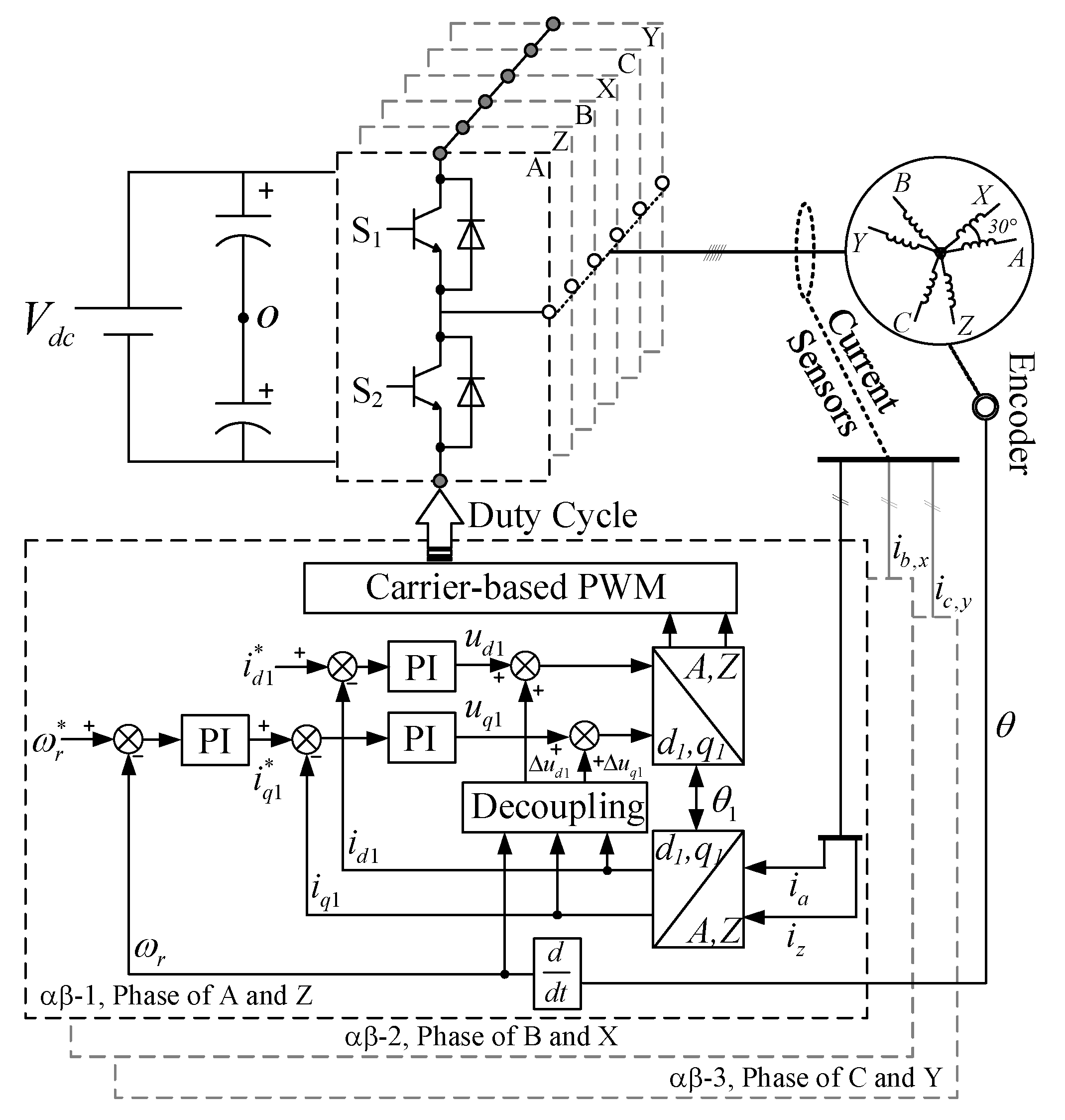
The suggested control scheme is illustrated in Figure 3. These three α-β reference frames are independent of each other. It converts the feedback currents to three sets of dq components via Park transformation. As mentioned, the d1, d2, d3 and q1, q2, q3 components are dc variables. The cross-coupling between d- and q-axis can be eliminated by the decoupling voltage terms feed-forward compensation for the output of the current controllers:
Δ u d 1 = ω e L q i q 1 Δ u q 1 = ω e L d i d 1 + ψ f d Δ u d 2 = ω e L q i q 2 Δ u q 2 = ω e L d i d 2 + ψ f d Δ u d 3 = ω e L q i q 3 Δ u q 3 = ω e L d i d 3 + ψ f d
Hence, the dq-currents can be effectively regulated without static errors by simple PI controllers. For surface-mounted PM machines, the reference currents of d1,2,3-axes set to zero are equivalent to maximum torque per ampere (MTPA), and the output of the speed regulator is as the common reference currents of q1,2,3-axes. It is obvious that the current PI controllers output phase voltages directly. The conventional stationary coordinate transformations between current PI controllers and phase voltages are avoided, which reduces the computation complexity. For synthesizing the required reference voltage vectors in the three d-q reference frames by a VSI, a carried-based PWM strategy was adopted since six different voltage vector components (ud1, uq1, ud2, uq2, ud3, uq3) are modulated in three decoupled parts simultaneously. Hence, each αβ reference frame can be seen as a control unit, which contains a speed regulator, current controllers, PWM, and two-phase inverter, respectively. It realizes the triple-redundancy control of dual three-phase machines.
Compared with conventional double-redundancy control, the proposed scheme has many advantageous properties. More redundancies mean better post-fault control performance. Hence, the most obvious one is the ease of implementation of high-performance fault-tolerant control. Furthermore, both neutrals can be preserved under open-phase faults. The current constraints can especially be released by changing the neutral connection. It provides the possibility of improving the post-fault control performance, which conventional double d-q control has lacked.

5. Experimental Results

5.1. Experimental Setup

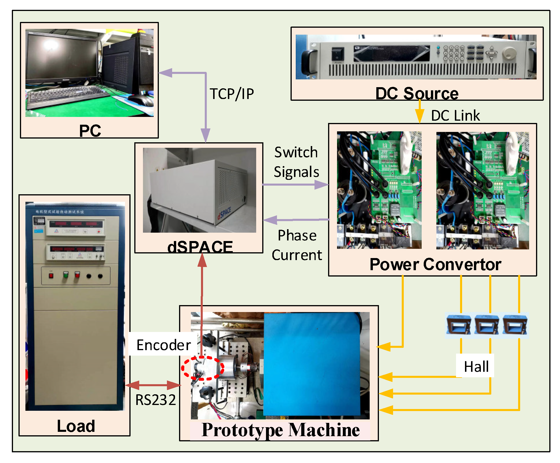
In order to verify the effectiveness of the proposed fault-tolerant control, an experiment platform was developed, which consists of two three-phase VSIs with a common dc link, a dual three-phase PM machine, and a dynamometer acting as the system load. Table 1 presents the parameters of the dual three-phase PM machine. Carrier-based PWM strategies are employed to generate PWM duties for each set. The VSIs operate at a switching frequency of 10 kHz. The setup includes an encoder for the rotor angle and speed feedback. The hardware platform based on dSPACE-1007 is shown in Figure 4.

5.2. Dynamic Performance Observation

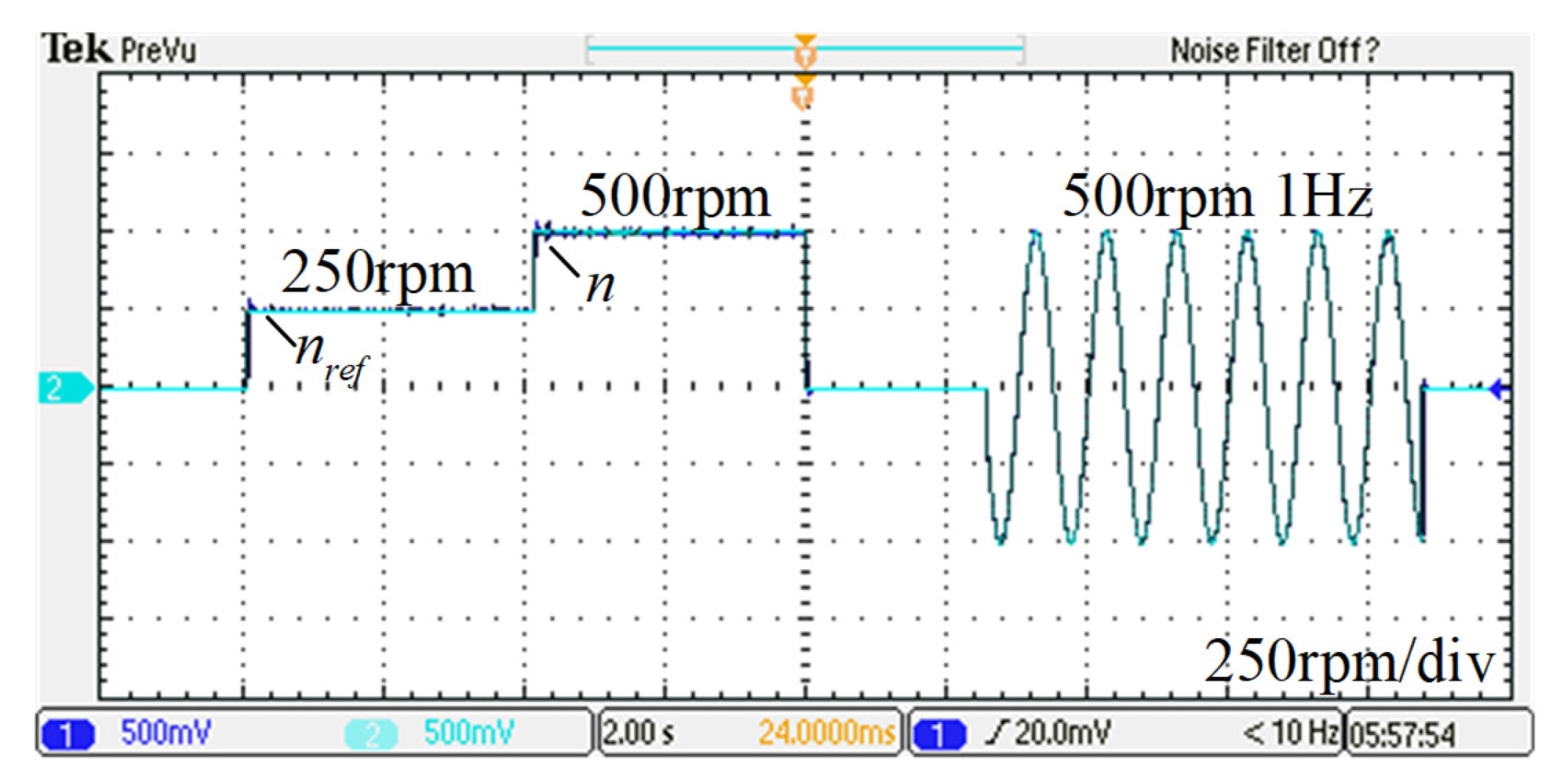
The dynamic preference was tested by step response of given speed. During this test, the reference speed was changed from 0 to 250 r/min, rising to 500 r/min, then falling to 0. At last, the prototype runs the continuous speed transient state (500 r/min, 1 Hz) without load. Figure 5 shows the experimental results. Obviously, the proposed method achieves high-speed tracking accuracy, and even the distinction cannot be seen in Figure 5.
In order to showcase the rise time of speed step response, the given speed was increased from 0 to 500 r/min directly, without load. The speed response curve and q-axis currents are shown in Figure 6. The rise time was 0.028 s, and the currents changed rapidly and consistently. This control strategy presents good dynamic performance.

5.3. Compensation of Imbalance Currents

Previous studies show that asymmetric phase resistance and back EMF harmonics may induce currents in the z1z2 sub-plane, which results in imbalanced currents between two winding sets and additional copper loss [21]. However, the conventional VSD is incompetent to eliminate currents in the z1z2 sub-plane. The prototype possesses nonsinusoidal back EMFs, which are suited to verify the balance control.
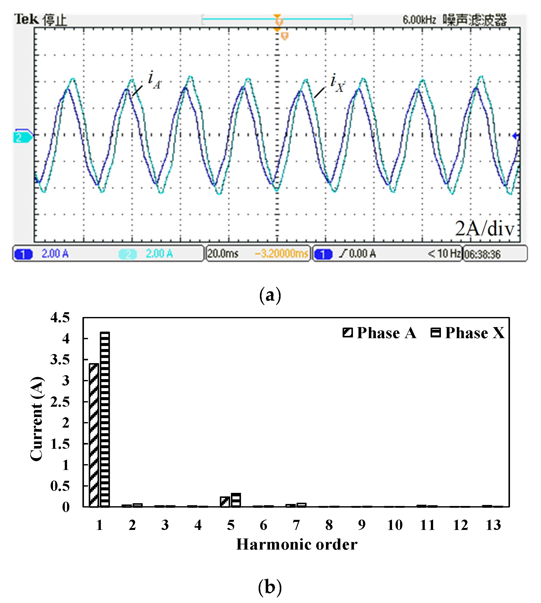
During this test, the machine runs with a rated speed (500 r/min) and rated load (3.5 N.m). The conventional VSD experimental results are shown in Figure 7a. The currents between two winding sets present asymmetry. One peak current is 3.4A, while the other is about 4.1A. The phase currents are not purely sinusoidal, as shown in Figure 7b; there is a fifth harmonic in the spectrum. It is evident that the conventional VSD is not capable of regulating currents in the z1z2 sub-plane effectively.
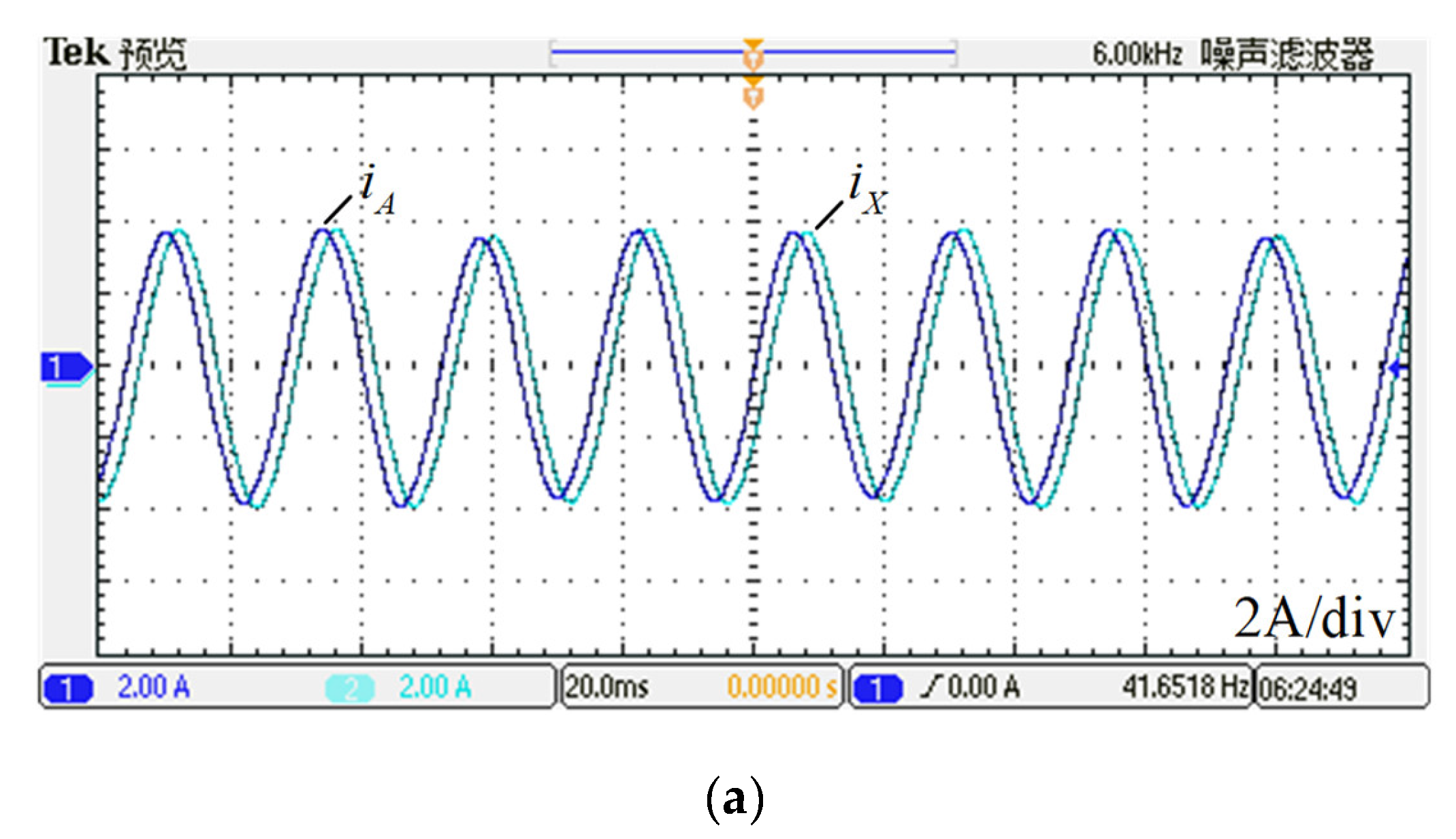
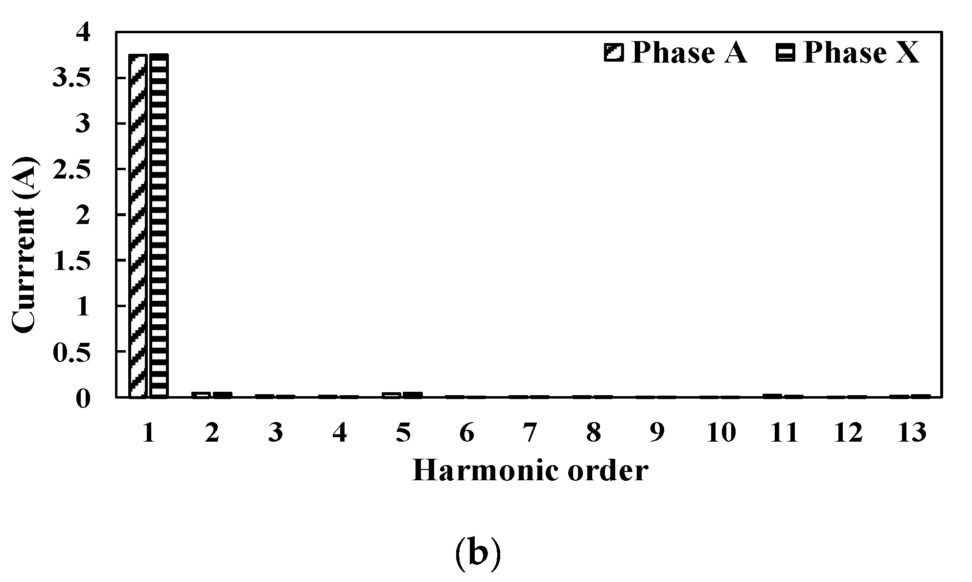
As a comparison, Figure 8a,b also shows the phase currents where the prototype was operated with the suggested control method in this paper. The phase peak currents of A and Z are both 3.7A. There are no current harmonics in the spectrum. It was concluded that the imbalance currents could be corrected with the triple stationary frame control scheme.

6. Conclusions

This paper proposes a vector control method for dual three-phase PM machines based on a triple stationary reference frame. The novel coordinate transformation and mathematical model were discussed. The fast dynamic response and imbalance of current inhibition were demonstrated by experiments. Compared with previous studies, the proposed method adopted three Park transformations to obtain the feedback of currents directly, omitting the complicated six dimensions transformed matrix. The vector control algorithm was simplified without sacrificing performance. The imbalanced currents caused by harmonic EMFs were suppressed effectively. Additionally, this suggested scheme theoretically achieves triple-redundancy control for dual three-phase machines. Although there is a lack of experimental verification, it is still a good solution for fault tolerance. Therefore, the proposed control scheme is suitable for high-speed machine applications, especially for the RMBMA system.

Author Contributions

Writing—original draft, J.-Y.Z.; Writing—review & editing, Q.Z. and K.W. All authors have read and agreed to the published version of the manuscript.

Funding

This work was supported in part by the National Natural Science Foundation of China (Project 61971431).

Conflicts of Interest

The authors declare no conflict of interest.

Nomenclature

uVoltageLaaqQ-axis self-inductance
iCurrentTeTorque
ψFluxpnPole pairs
RResistanceθeRotor position
Wcmagnetic co energyθmMechanical position
Lsinductance matrixωeElectric angular frequency
LaalLeakage inductanceIsCurrent matrix
LaadD-axis self-inductanceψsFlux matrix

References

  1. Barani, N.; Sarabandi, K. Mechanical Antennas: Emerging Solution for Very-Low Frequency (VLF) Communication. In Proceedings of the 2018 IEEE International Symposium on Antennas and Propagation & USNC/URSI National Radio Science Meeting, Boston, MA, USA, 8–13 July 2018; pp. 95–96. [Google Scholar] [CrossRef]
  2. Bickford, J.A.; Duwel, A.E.; Weinberg, M.S.; McNabb, R.S.; Freeman, D.K.; Ward, P.A. Performance of Electrically Small Conventional and Mechanical Antennas. IEEE Trans. Antennas Propag. 2019, 67, 2209–2223. [Google Scholar] [CrossRef]
  3. Gong, S.; Liu, Y.; Liu, Y. A Rotating-magnet based mechanical antenna (RMBMA) for ELF-ULF wireless communication. Prog. Electromagn. Res. M 2018, 72, 125–133. [Google Scholar] [CrossRef] [Green Version]
  4. Prasad, M.N.S.; Huang, Y.K.; Wang, E. Going beyond Chu Harrington limit: ULF radiation with a spinning magnet array. In Proceedings of the 2017 XXXIInd General Assembly and Scientific Symposium of the International Union of Radio Science (URSI GASS), Montreal, QC, Canada, 19–26 August 2017. [Google Scholar]
  5. Selvin, S.; Prasad, M.S.; Huang, Y.; Wang, E. Spinning magnet antenna for VLF transmitting. In Proceedings of the 2017 IEEE International Symposium on Antennas and Propagation & USNC/URSI National Radio Science Meeting, San Diego, CA, USA, 9–14 July 2017. [Google Scholar]
  6. Prasad, M.S.; Selvin, S.; Tok, R.U.; Huang, Y.; Wang, Y. Directly modulated spinning magnet arrays for ULF communications. In Proceedings of the 2018 IEEE Radio and Wireless Symposium (RWS), Anaheim, CA, USA, 15–18 January 2018; pp. 171–173. [Google Scholar]
  7. Fawole, O.C.; Tabib-Azar, M. An electromechanically modulated permanent magnet antenna for wireless communication in Harsh electromagnetic environments. IEEE Trans. Antennas Propag. 2017, 65, 6927–6936. [Google Scholar] [CrossRef]
  8. Lyra, R.O.C.; Lipo, T.A. Torque density improvement in a six-phase induction motor with third harmonic current in-jection. IEEE Trans. Ind. Appl. 2022, 38, 1351–1360. [Google Scholar] [CrossRef] [Green Version]
  9. Hu, Y.S.; Zhu, Z.Q.; Odavic, M. Torque capability enhancement of dual three-phase pmsm drive with fifth and seventh current harmonics injection. IEEE Trans. Ind. Appl. 2017, 53, 4526–4535. [Google Scholar] [CrossRef]
  10. Wang, K.; Zhang, J.Y.; Gu, Z.Y.; Sun, H.Y.; Zhu, Z.Q. Torque Improvement of Dual Three-Phase Permanent Magnet Machine Using Zero Sequence Components. IEEE Trans. Magn. 2017, 53, 8109004. [Google Scholar] [CrossRef]
  11. Levi, E. Multiphase Electric Machines for Variable-Speed Applications. IEEE Trans. Ind. Electron. 2008, 55, 1893–1909. [Google Scholar] [CrossRef]
  12. Eldeeb, H.M.; Abdel-Khalik, A.S.; Hackl, C.M. Dynamic Modeling of Dual Three-Phase IPMSM Drives with Different Neutral Configurations. IEEE Trans. Ind. Electron. 2019, 66, 141–151. [Google Scholar] [CrossRef]
  13. Karttunen, J.; Kallio, S.; Peltoniemi, P.; Silventoinen, P.; Pyrhonen, O. Decoupled Vector Control Scheme for Dual Three-Phase Permanent Magnet Synchronous Machines. IEEE Trans. Ind. Electron. 2014, 61, 2185–2196. [Google Scholar] [CrossRef]
  14. Che, H.S.; Levi, E.; Jones, M.; Hew, W.-P.; Rahim, N.A. Current Control Methods for an Asymmetrical Six-Phase Induction Motor Drive. IEEE Trans. Power Electron. 2014, 29, 407–417. [Google Scholar] [CrossRef] [Green Version]
  15. Bojoi, I.R.; Tenconi, A.; Griva, G.; Profumo, F. Vector control of dual-three phase induction motor drives using two current sensors. IEEE Trans. Ind. Appl. 2006, 42, 1284–1292. [Google Scholar] [CrossRef]
  16. Singh, G.; Nam, K.; Lim, S. A Simple Indirect Field-Oriented Control Scheme for Multiphase Induction Machine. IEEE Trans. Ind. Electron. 2005, 52, 1177–1184. [Google Scholar] [CrossRef]
  17. Duran, M.; Kouro, S.; Wu, B.; Levi, E.; Barrero, F.; Alepuz, S. Six-phase PMSG wind energy conversion system based on medium-voltage multilevel converter. In Proceedings of the 2011 14th European Conference on Power Electronics and Applications, Birmingham, UK, 30 August–1 September 2011; pp. 1–10. [Google Scholar]
  18. He, Y.; Wang, Y.; Wu, J.; Feng, Y.; Liu, J. A simple current sharing scheme for dual three-phase permanent-magnet synchronous motor drives. In Proceedings of the 2010 Twenty-Fifth Annual IEEE Applied Power Electronics Conference and Exposition (APEC), Palm Springs, CA, USA, 21–25 February 2010; pp. 1093–1096. [Google Scholar] [CrossRef]
  19. Wang, X.; Wang, Z.; Gu, M.; Xiao, D.; He, J.; Emadi, A. Diagnosis-Free Self-Healing Scheme for Open-Circuit Faults in Dual Three-Phase PMSM Drives. IEEE Trans. Power Electron. 2020, 35, 12053–12071. [Google Scholar] [CrossRef]
  20. Barrero, F.; Duran, M.J. Recent advances in the design, modeling, and control of multiphase machines—Part I. IEEE Trans. Ind. Electron. 2016, 63, 449–458. [Google Scholar] [CrossRef]
  21. Hu, Y.; Zhu, Z.-Q.; Liu, K. Current Control for Dual Three-Phase Permanent Magnet Synchronous Motors Accounting for Current Unbalance and Harmonics. IEEE J. Emerg. Sel. Top. Power Electron. 2014, 2, 272–284. [Google Scholar] [CrossRef]
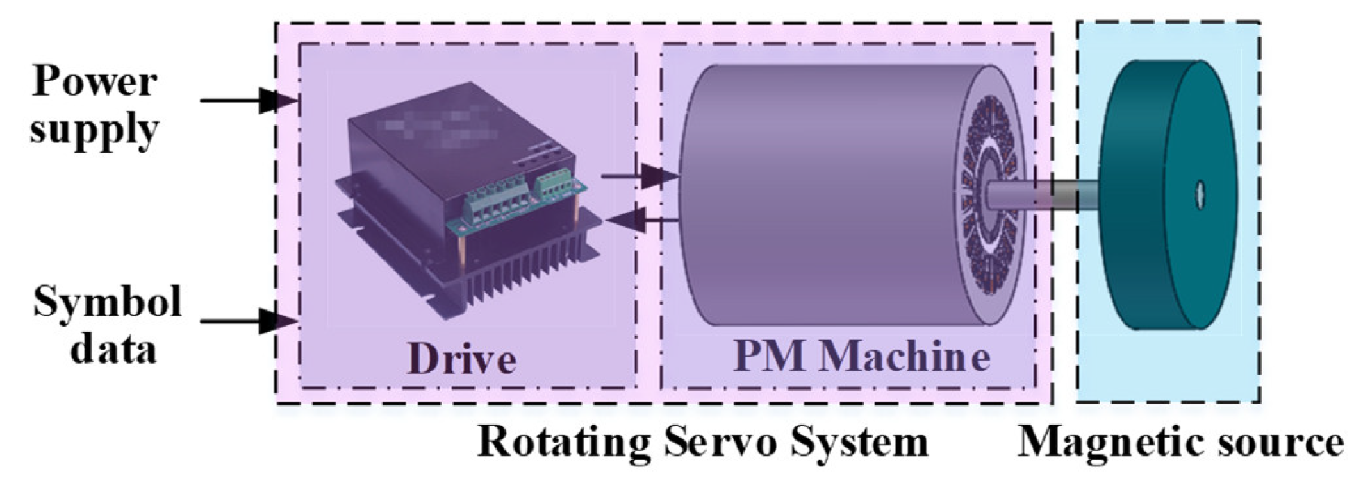
Figure 1. Typical RMBMA architecture.
Energies 15 07286 g001
Figure 2. Decoupled three d-q coordinates, (a) dual three-phase windings, (b) d1-q1 reference frame; (c) d2-q2 reference frame; (d) d3-q3 reference frame.
Energies 15 07286 g002
Figure 3. Control scheme of triple stationary frame.
Energies 15 07286 g003
Figure 4. Experiment setup for dual three-phase PMSM drive testing.
Energies 15 07286 g004
Figure 5. Continuous speed transient state: Channel 1: actual speed, Channel 2: reference speed (250 rpm/div), Horizontal: Time (2 s/div).
Energies 15 07286 g005
Figure 6. Step response of given speed, (a) speed: Channel 1: actual speed, Channel 2: reference speed (250 rpm/div), Horizontal: Time (0.02 s/div); (b) q-axis currents: Channel 1: q1, Channel 2: q2, Channel 3: q3, (5A/div), Horizontal: Time (0.02 s/div). (PS: “预览” means preview, “噪声滤波器” means Noise Filter).
Energies 15 07286 g006
Figure 7. Experimental results with conventional VSD, (a) currents: Channel 1: phase of A, Channel 2: phase of X (2A/div), Horizontal: Time (0.02 s/div); (b) corresponding harmonics analysis. (PS: “停止” means stop, “噪声滤波器” means Noise Filter).
Energies 15 07286 g007
Figure 8. Experimental results with triple stationary control, (a) currents: Channel 1: phase of A, Channel 2: phase of X (2A/div), Horizontal: Time (0.02 s/div); (b) corresponding harmonics analysis. (PS: “预览” means preview, “噪声滤波器” means Noise Filter).
Energies 15 07286 g008aEnergies 15 07286 g008b
Table 1. Parameters of dual three-phase PM machine.
ParameterValue
Resistance (Ω)0.48
Leakage inductance (mH)0.262
d-axis self-inductance (mH)0.28
q-axis self-inductance (mH)0.28
PM flux linkage (Wb)0.07
Pole pairs5
DC link voltage (V)50
Publisher’s Note: MDPI stays neutral with regard to jurisdictional claims in published maps and institutional affiliations.