1. Introduction
Current environmental concerns in the energy generation sector have led to the rapid deployment of distributed energy sources, mainly in the form of alternative generation systems based on renewable resources. The increasing numbers in distributed generation have created paradigms in the control, coordination, management, and operation areas of such assets. This has motivated research interest towards microgrid systems as entities within distribution systems capable of coordinating the distributed generation with management and regulation capabilities. Since microgrids can be seen as a single entity within the electrical network, the quality control and management paradigms behind the distributed generation of electrical energy are simplified. In this sense, the how, when, and where the energy is consumed or generated, and the protection challenges that follow the physical and digital layers that compose its architecture can be handled in a simpler manner [
1].
The right integration of solutions to the individual paradigms that fall into the many research categories that follow the microgrid topic can help to achieve a functional and reliable implementation of a microgrid system. Currently, microgrids are deployed in two formats, grid-connected and autonomous or island systems. The former functions as a complimentary service that contributes to the overall power demand while locally feeding a set of connected loads, the latter format being an independent system capable of self-managing and self-balancing the power generation and consumption rates to fully cover for electricity demand of isolated or energy-deprived communities while regulating electrical variables such as the microgrid voltage and frequency [
2].
Microgrids are systems that require extensive studies and tests before their deployment to avoid any shortcomings in their performance due to unexpected scenarios that can even result in system faults that compromise the integrity of the generation and consumption assets connected to the distribution system [
1]. These unexpected scenarios can be described as anomalies in the expected operating conditions of microgrid systems, such anomalies can be a miss prediction of weather conditions, overload conditions due to a higher power demand, and unexpected changes in the operation mode of the microgrid, causing difficulties in the decision-making process of Energy Management Systems (EMS) and in low-level power converter devices to correctly assess the derived problematics.
These scenarios can trigger faults at any of the three operation levels of microgrids according to the hierarchical control architecture described in the literature [
3,
4]. Faults that occur at the tertiary level commonly deal with the management of resources and interrupted communication channels between the central controller and the governed assets. Faults at the secondary level affect the power-sharing capabilities among the generation units, causing a mismatch of delivered active and reactive power by the governed generation units and leading to harsh circulating reactive power by all of the generation agents and inducing instability in the distribution system [
5]. Lastly, faults at the primary level are mainly found in power converter systems such as DC to DC, AC to DC, and DC to AC converters; these types of faults are technically more challenging since these can occur at the component and system levels where its identification or amendment can become costly and in a difficult process, especially in multi-level converter topologies. Component level faults deal with corrupt switching devices or other sub-components in the systems such as the associated diodes and DC link capacitors; component faults are mainly attributed to over-current and over-heating conditions that hinder the performance and have a negative impact on the expected lifespan of the semiconductors within the power converter system.
Open circuit faults can be classified in single phase, two-phase, or three phase. The basic type is the “single phase”, and the rest of the open circuit faults are derived from it. This mainly occurs because one of the wires of the transmission line gets open (this can happen due to joint failure or broken conductor) and precludes the current from flowing through the wires. The effects that an open circuit fault can have are: (i) unbalanced load current; (ii) abnormal voltage and current behavior; (iii) danger to individuals surrounding the grid; and (iv) complete system shutdowns [
6].
System shutdowns compromise the integrity of the microgrid and its assets; for that reason, the topics of fault detection and identification have gained popularity in the past decades. Mainly three categories for fault detection in switching power converters can be obtained from the literature: sub-component, system-based, and model-based. Sub-component techniques are known for being embedded in the power converter system and monitoring the gate signal of the switching devices for over-current and overheating conditions. The second category can be further divided into waveform analysis and algorithmic techniques [
6]. System fault detection through waveform techniques operates by analyzing the voltage and current waveforms and comparing them against nominal system indicators to determine the fault type and location; however, this type of fault detection technique is known for being sensitive to unbalanced load conditions and large load switching scenarios, causing false tripping signals.
On the other hand, algorithmic strategies are implemented along with classifier algorithms such as neural networks, fuzzy logic, logistic regression, and decision trees, where their performance depends on the training procedure and the data obtained to train the classifiers. The latter model-based technique compares system measurement to estimated values according to a defined simulated model implemented in an offline system, the accuracy of model-based techniques depends highly on the simulated digital model and employed simulation tool to match the fast dynamics of the power systems, where an inaccurate or an inconsistent dynamic representation of the system would result in an erroneous fault diagnostic [
7]. Thankfully, in recent years, the validation of microgrid and power systems technologies has been heavily supported by Real-Time (RT) simulation technologies that ensure the dynamic consistency of the proposed systems. According to Ibarra et al. [
8], RT systems offer a safe path toward the simulation, test, and validation of complex and dangerous systems against novel hardware or software proposals, minimizing risks for the user and physical systems when dealing with high voltage or high current power systems. In addition, RT is an attractive tool for the expansion of cost-compelling technologies and solutions by closing the gap between the initial concept and its implementation or rejection.
As an example in the application of RT simulation in the power and energy sector, Lu et al. [
9] proposes a low-cost RT Hardware-in-the-loop (HIL) system to test and validate the performance of power electronic controllers in applications that include a DC-DC boost converter and single-phase inverter systems; overall, the proposed RT system proposed by Lu et al. [
9] achieves a good resolution to ensure the dynamic consistency of most power electronic devices. In a different power systems application, Ref. [
10] uses an HIL setup to validate their proposal on a decentralized islanding detection algorithm for microgrid systems, the proposed HIL platform ensures the dynamic consistency of a microgrid equivalent model while the proposed decentralized island detection algorithm is embedded in a separate RT platform and running at its own step time. In general, the proposed RT validation setup ensures the dynamic consistency of the islanding detection proposal and the simulated microgrid equivalent model.
In the power systems fault detection landscape, the work presented by Poon et al. [
11] uses an RT validation approach in their proposal of model-based fault detection and identification algorithm for switching power converters, such algorithm is based on a state estimator to identify faults related to components and system sensors, the fault identification process is carried out by comparing the measured voltage from the system against an estimated voltage. Overall, the state estimator proposal is validated through an HIL setup, demonstrating its capability to identify component level faults according to the programmed model of the power converter model, providing a generic approach toward fault identification. Particularly, the proposed model-based method identifies open circuit faults in inverter-based systems within 3.45 ms.
In a different approach, the work reported by Estima and Marques Cardoso [
12] successfully identifies open circuit faults in an inverter based system, the proposed system-based technique takes into consideration the average absolute values of the measured current to create a threshold that can identify the occurrence of open circuit faults with in 1.13 ms, additionally, Estima and Marques Cardoso [
12] also integrates an HIL strategy to validate their proposal. Nonetheless, despite being validated in an HIL setup, such implementations are intended to be embedded within the control system of the power converters which can fall short of the required computational power to guarantee the dynamic consistency of the configured power converter model and fail as a fault identification distributed approach. Real-time simulation has been used to give a better approach when HIL is integrated because it is possible to obtain a real time simulation running with the same dynamic response in real time as the experimental system. Thus, several hardware elements could be evaluated in the same system. On the other hand, conventional simulation and co-simulation have been shown to provide a good response when comparing offline against the experimental system. In addition, conventional simulation is the first step to evaluating HIL in real-time simulation. As a result, both conventional and real time simulation could provide excellent results when offline simulations are evaluated.
Despite the efforts of having a proposal validated through RT simulation, model-based fault identification methods still require accurate models and platforms with the capacity to accurately replicate the real-life dynamics of these complex systems. To overcome such limitations, new digital representation technologies have emerged across the literature, where now the digital representation of a system is referred to as a Digital Twin (DT) [
13,
14]. Conventionally, the DT process is carried out in a digital simulation environment with real data as the input of the system; in this environment, the modeling, prediction, testing, and validation of a given scenario and problem are obtained rapidly to effectively send any correcting actions to the real system through a feedback channel. Nonetheless, little is known about the development of DTs and how the design process can affect the outcome of this digital counterpart. In such understanding, the work presented by Solman et al. [
15] reviews the different actors that are included in the planning and deployment of DTs, the work concludes with a list of five key areas to take into consideration when planning a DT related to problematics in the energy generation sector: (i) energy generation system design, (ii) data to be used, (iii) define constraints of public engagement, (iv) simplification and selection of data according to energy-related challenges, and (v) select attributes to be digitized.
Within the energy landscape, DTs have emerged as a technological solution to energy management and operation paradigms. In the work presented by Jafari et al. [
16], it is stated that DTs aid building owners and operators in predictive failure and fault diagnosis, execute what-if scenarios to analyze the system response to parametric or operational parameters, and carry out planning and resource analysis for performance optimization; overall, such work proposes a novel DT architecture for improved building energy management that results in a more sustainable system thanks to the intercommunication between business models, analytic engines, with the digital counterpart. A similar study is conducted by Onile et al. [
17], where DT is explored as a tool for improving the smart management of energy generation according to demand side management strategies related to consumer behavior to predict and improve energy-related services. However, it is important to understand that this digital validation process is not always the best alternative in systems with a high degree of complexity, mainly because the conventional simulation environment can be a reason to have unmatched dynamics of the interfaced agents and result in unfeasible solutions.
An unfeasible solution could potentially lead to a failure of the real system even with the application of DTs in power systems. Therefore, this work proposes a framework for fault identification in a power system that encloses the DT in an interfaced distributed generation unit within an RT environment to avoid erroneous DT results due to inconsistent dynamics. In the proposed framework, fault identification is achieved by merging the operation of an algorithmic and model-based identification strategy. A Self-Organizing-Map (SOM) Neural Network is implemented and trained to detect and identify power system faults, while a DT model of the interfaced power converter is assembled for comparison between a real system and its digital replica. The proposed framework is validated in a case study for three-phase and single-phase open circuit faults in a three-phase inverter-based system.The main contribution of our work can be summarized as a fault identification framework for a three-phase inverter system, where the principles of DTs, RT simulation, and ML are combined to generate a simulation environment that can cope with the fast dynamics of power systems and generate an adequate platform for implementing online fault detection based on an ML clustering technique, resulting in a reliable fault identification tool that works in parallel with an experimental system.
The remainder of this work is structured as follows;
Section 2 shows the DT concept in the microgrid scheme;
Section 3 elaborates more on RT simulation as a validation strategy for microgrid technologies;
Section 4 gives a brief introduction to the application of Machine Learning in the microgrid scope;
Section 5 gives the description on the proposed fault identification framework;
Section 6 provides details on the case study used to validate this work’s proposal;
Section 7 gives the experimental results and
Section 8 opens the discussion and future trends of DT technologies in the power system landscape. Lastly,
Section 9 gives the conclusions of this work.
2. Digital-Twin Concept in the Microgrid Scheme
In the electric sector, as in different industries, many decision-making actions are taken thanks to the acquired result from a digital model. Commonly, the data fed into the digital model are obtained via extensive pre-studies that analyze the past behavior of consumers, utilities, industries, or environments. For the microgrid, these data points are represented by the fluctuation analysis of the energy market, time-of-use tariff profiles, historical weather information, just to mention a few. These data are later used to formulate a model that can help in the decision-making task of managing the microgrid system more efficiently.
Nonetheless, this approach relies heavily on the recorded data during past events. This means that the recorded data are directly correlated to the system for which it was obtained. This statement indicates that any parametric changes in the real system can affect the predicted outcome of the model. For that matter, emerging technologies such as the DT make use of running system data to predict the behavior of the real system. The DT approach minimizes the dependency on past modeling and prediction methods. Allow a tailored management experience according to the ongoing scenarios.
Essentially, the objective of a DT is to develop a digital reproduction of a physical system. DTs are capable of mimicking the dynamics and functionality of their physical counterparts. NASA defines the DT as a multiphysics, multiscale, probabilistic simulation of a physical system that makes use of accurate physical models, sensor data, and performance history to resemble the outcome of its real equivalent [
18].
According to the literature review, a DT can be constituted from three to five main areas. For example, the work presented in [
19] defines the DT as a constitution of five elements: (i) physical system, (ii) virtual environment, (iii) provided service, (iv) acquired data, and (v) communication link between the real and the virtual environment. On the other hand, Wang et al. [
20] clarify that, by following the NASA definition, the DT concept can be formed in only three dimensions, the physical product, the virtual model, and the bi-directional communication link in between the two. In the end, the convolution of these key areas helps to define a monitoring scheme capable of providing valuable data regarding a real system; this contributes to the early detection of anomalies and complexities, while improving the forecast of operational conditions.
In another study presented in [
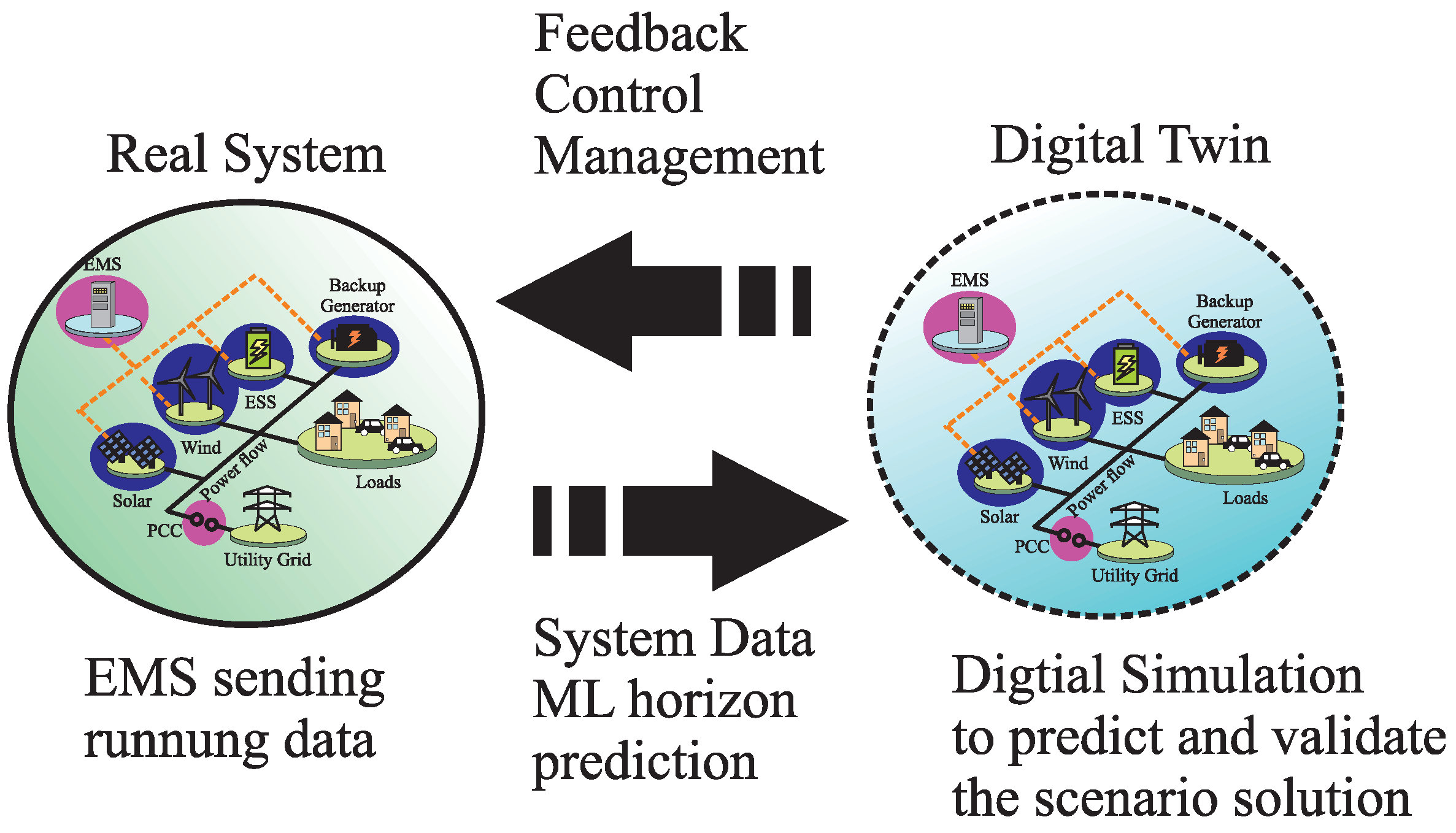
21], it is stated that the DT can have several definitions depending on the industry of application. The DT can be segregated in: (i) conventional; (ii) prototype; (iii) instance; and (iv) environment. Regardless of these partitions, the essential objective of the DT remains the same, only changing in the area of application, the DT prototype definition is suited for application in the energy industry. The DT prototype concept is defined as a digital representation of a real artifact, where all the information required to mimic the real implementation is self-contained in the virtual system. By following this definition, the microgrid can be comprehended as the real artifact, all the information of the many components is self-contained within the model and only the running data are fed into the DT to predict the microgrid’s behavior.
Figure 1 shows a scheme of how the DT definition can be applied to the microgrid.
In the first partition of the microgrid’s DT scheme, the active participation of the real system is defined by the collection and sent data, these actions are achieved by an established AMI and the microgrid’s EMS, capturing raw sensor data and allowing a seamless flow of information from the many assets to the microgrid’s main operator. The sent data contain information regarding the state of the many participating agents, including their consumption and generation readings. Subsequently, the running data are used to create and update the system’s model through AI techniques.
AI has been a key factor driving the current development of DT technologies. With the integration of the virtualization process and AI, the structure, context, and dynamics of a real system allow not just the monitoring of past and present operations, but also enable prediction capabilities about future events, leading to self-healing models that adapt to their real twins [
22]. Once the data-driven analytics stage is complete, the output data are then simulated in a physics-based model of the real system. In this stage, computational simulation is commonly the main platform for which a given scenario is validated. This leads to the final stage, where the validated outcome is fed back into the real system, closing the communication loop between the real implementation and its digital counterpart.
Overall, the application of DT technologies to the microgrid’s operation opens the door for a tailored management experience in key opportunity areas that help in the performance and sustainability of the small-scale distributed electrical network: the optimization of its performance, prediction of preventive and corrective maintenance, planning the expansion development in generation and consumption capacity, and optimization of urban sustainability [
22]. Indeed, all of these features are enabled through DT technology. However, due to the dynamic complexity and constant expansion of power systems, traditional validation methods such as computational simulation can hinder DT performance. For that matter, other validation tools can be adopted to improve the validation stage of the DT scheme in complex systems such as the microgrid.
3. Real-Time Simulation as a Validation Structure
Traditionally, the validation process within the DT concept is carried out in an online digital simulation environment. Although this validation strategy can be sufficient for other processes in the manufacturing manufacturing area, the challenge that comes with the complex dynamics of power systems requires more effective validation strategies. RT simulation has been gaining popularity as a validation tool to overcome the dynamic complexity of power systems and offering a high degree of fidelity as studied by Sekine et al. [
23] in 1994.
A central characteristic of RT simulation is the capability of offering a resembling approximation to the real system dynamics by virtue of guaranteeing the dynamic consistency of the simulated model. Dynamic consistency is an attribute formed by the task to be done and the time-step (Ts) of the simulation, essentially, to achieve the dynamic consistency, the tasks to be done need to start at a deterministic Ts and finish before the next Ts begins [
24]. However, in traditional simulation environments, where the TS and the task to be done do not follow this deterministic behaviour. In example, discrete simulation operates with a fixed TS; however, the task of the simulation can start and/or end at any giving time of the simulation, meaning that these can be completed after or before the next fixed Ts. Similarly, continuous simulation adapts the Ts according to the task at hand; this results in a simulation that does not have a deterministic Ts, therefore the dynamic consistency of the simulated model can not be guaranteed. A comparison of these simulation environments is illustrated in
Figure 2.
As mentioned in a previews section, RT simulation is a tool used in many engineering fields, where many industries and research groups take good advantage of this simulation technology by testing and simulating control, software, and high-power level management strategies without compromising the integrity of the personnel and/or real equipment. In addition, RT opens the door to new validation strategies such as Co-simulation, HIL, Hardware-Under-test (HUT), and Power-Hardware-in-the-Loop (PHIL) simulation methods, each with its unique characteristics and favored areas of application.
To begin, the co-simulation strategy aids to reduce the complexity of simulations that require the contribution of multiple systems for the resolution of a given model. This strategy divides core parts of given problematic and combines multiple simulation platforms to generate a holistic test environment. Essentially, the system of interest is segregated into a finite number of core modules, then each module is simulated in single but interconnected, simulation environments. As an example, Zhang et al. [
25] presents a co-simulation environment that validates the right interaction of multiple power systems before the actual implementation; such proposal divides the entire system in three modules, a hybrid power grid, a 500 KV transformer, and the electromagnetic transients and finite analysis calculation-model. In such arrangement, the validation of such systems is achieved without the direct interaction with real and industrial equipment.
As a different approach, HIL adopts embedded systems to test and validate novel control or software proposals. In an HIL strategy, the end product is downloaded to an embedded system and interfaced via bidirectional communication channels with the RT simulation environment where the plant or physical system is being simulated. In doing so, the embedded system is assured to act over the real-dynamics of their intended target, thus the validation of its operation is achieved before it actual implementation. According to Bélanger and Venne [
24], HIL allows for more repeatable testing results; since the dynamics of the simulated system remain the same across the entire simulation, unlike in physical systems, the dynamic response could change. HIL strategy helps to accelerate the integration and verification stages within the development process of an idea, something that is hardly achieved by offline simulation [
24].
Lastly, PHIL is defined by Omar Faruque et al. [
26] as any HIL setup where power transfer is done to or from a hardware unit, this is achieved by the implementation of power amplifiers or sensors. For other authors, a PHIL strategy requires a power amplifier stage and a sensing stage, to properly close the loop between the hardware and simulation interface [
8]. PHIL is used more in power systems since this strategy includes a power exchange layer between tested hardware and the RT simulation environment. This strategy is preferred to test and validate novel control or management proposal in high-power systems, as it offers a safe simulation space for the users and the equipment. Overall, these strategies contribute to the early detection of faults and reduce the need for extensive testing.
In this work, command signals are sent to the inverter, and a model is running in real time simulation, so the real time model and the power electronics stage are interacting in real time. This is considered an HIL. For instance, sending command signals to the inverter through a DSP is not considered an HIL since no real-time digital model is running into the real time simulation. In addition, real time simulation solves the model according to the real time dynamics of the experimental system to be connected with the hardware. Thus, the model running in the real time simulation can maintain the same dynamic response so that repeatable testing can be conducted. In the experimental system, parameters and initial conditions could change, so repeatable testing is difficult to accomplish. In any case, the HIL strategy fulfills the requirement of having an RT simulation that can emulate and validate such test cases with high fidelity. This presents simulation models that can be monitored as DT. In this work, RT simulation creates an adequate environment for the generation of DT of complex power systems.
4. Machine Learning in the Microgrid Landscape
We are now at a stage where technology is able to take advantage of the advances made in artificial intelligence algorithms which allow faster convergence, manipulating massive amounts of data, and solving increasingly more complex problems. One of the methods of artificial intelligence employed on the microgrid is Machine Learning. According to Dangeti [
27], Machine Learning (ML) is defined as the branch of computer science that utilizes experience to learn from and use its knowledge to make future decisions. The goal of ML is to generalize a detectable pattern or to create an unknown rule from given examples.
ML has been used several times at the academic and enterprise level given that it has shown its usefulness by extracting meaningful data from raw environmental interaction. One of the keys to using ML is selecting an appropriate algorithm for the task at hand (classification, detection, prediction, optimization, etc.); this affects the ability to predict and accurately divide into groups the data fed to the system.
Figure 3 shows different categories for training machine learning systems and some of the most commonly used algorithms.
Each algorithm has its own application scope and can not be used to solve every problem;
Table 1 and
Table 2 show some of the advantages and disadvantages of said algorithms.
For the specific case study of this work (microgrids), some examples of the use of ML are reported by Almutairy and Alluhaidan [
28] and Ali et al. [
29]. In the former case [
28], a fault diagnosis framework becomes feasible with the inclusion of ML. In such an article, a DC microgrid is introduced as a case study where an AC grid is also connected through a rectifier; in addition, photovoltaic panels, battery storage, and loads are all connected to the main DC bus. An artificial Neural Network (ANN) is trained with data for the line changing current by analyzing the current slope angle, thus determining if a short circuit occurred. The ANN is trained to recognize the angle at which a fault is produced (near 90
. This ANN is then connected to a circuit breaker to isolate the segment of the Microgrid producing the fault, avoiding further damage to the grid.
In the latter example of ML application [
29], it is demonstrated that microgrid problematics such as islanding events identification can also be addressed through the use of machine learning as proposed by Ali et al. [
29]. Islanding detection is vital on the microgrid for efficiency rising and according to
IEEE 1547 standard; this scenario should be detected within 2 s. This study shows an ANN trained offline with data gathered by multiple simulations of islanding scenarios in
MATLAB Simulink. ML is used in this scenario given that the threshold has a sweet spot that this algorithm was able to learn, if this threshold is not accurately spotted, it can produce a non-detection zone for islanding scenarios. The goal of achieving islanding detection using ML was achieved within 100 ms and without any nondetection zones.
Self Organizing Map (SOM) has multiple applications as shown in [
30] for profiling and forecasting at the microgrid level and [
31] for load forecasting. SOM is a powerful clustering algorithm, where surrounding neighborhood data can belong to one neighboring cluster or a close one. It was introduced by Kohonen [
32] inspired by biological processes. It models the plasticity of the connections in the brain, where the neural connections either get strengthened or disappear while learning.
In an SOM or Kohonen network, for a map that has I units, each unit compares its weight vector to the input vector
. Through an iterative process, each weight gets altered every epoch, and these changes are dependent on the similarities between the neighborhoods (how close the input pattern is to the map pattern) [
33]. This is measured by calculating the Euclidean distance from x to all weight vectors. The neuron with values closer to the input vector ones is called the Best Matching Unit (BMU). As listed in the Advantage for Self Organizing Map in
Table 2, real-time implementation is possible with this algorithm. As the BMU is found, the update process for the weights vectors gets started, and the BMU is re-arranged in a way that gets closer to the input vector. In the following sections, it will be shown how it can be implemented for fault detection on a DT scheme for the microgrid application.
7. Experimental Results and Discussion
The proposed fault identification framework is validated in an experimental setup. The previously described system and hardware setup are tested against four different types of open circuits since these do not cause serious damage to the equipment and comply with the safety laboratory protocols. In addition, each phase is tested individually, in order to guarantee a decoupled identification of the trained clustering neural network as also tested by Poon et al. [
11]. The first test consists of the identification of a three-phase open circuit fault; this test is performed by manually disconnecting the three phases from the HIL data acquisition interface. In doing so, a triggering signal is generated in the oscilloscope, where the output of each SOM can also be observed. Each SOM is tested separately; first,
Figure 14 shows the result of the small SOM, highlighting the successful detection of a three-phase open circuit fault in a total time of 13 ms of its occurrence. In the same test with the bigger SOM, the detection time demonstrated being faster with a detection time of 200
s; the results for the bigger SOM are shown in
Figure 15.
The following test consists of identifying single-phase open circuit faults. This is done by manually disconnecting each phase at separate times; each disconnection causes a trigger event that activates the reading of the oscilloscope. Once again, each test is done separately for each SOM;
Figure 16 shows the results of successful identification of an open-circuit fault in phase A for the small SOM, while
Figure 17 shows the results for the same test scenario for the bigger SOM; the results for each test are 13 ms for the small SOM and 70
s for the bigger SOM.
In the same test condition, phases’ open-circuit faults are tested for phase B. In each case, the bigger SOM resulted in a faster detection time for open-circuit faults. The results for phase B are shown in
Figure 18 and
Figure 19 for the small and bigger SOM, respectively. The detection times are obtained as 1.6 ms for the small SOM and 80
s for the bigger SOM.
Lastly, open-circuit faults’ tests for phase C is carried out by following the same disconnection procedure for each SOM. Coincident with the above results, the smaller SOM had a higher fault identification time, with obtained detection times of 1.4 ms and 100
s for the small and bigger SOM, respectively. The experimental results for phase C are shown in
Figure 20 and
Figure 21 for the small and bigger SOM, respectively.
Compared with the different fault identification methods found during the literature review, the proposed fault identification framework offers a simple, noninvasive, and fast identification approach for single and three-phase open circuit faults. When compared to the work proposed by Poon et al. [
11], the proposed RT fault identification framework does not separate the detection and the identification stages; on the contrary, these stages happen at the same time, resulting in a faster detection time despite the size of the SOM, with identification scores two times faster for single-phase open circuit faults. On the other hand, when the proposed method is compared against the system-based method proposed by Estima and Marques Cardoso [
12], only the bigger SOM results in an identification time score from 11 to 16 times faster for single-phase open circuit faults. In addition, the proposed method in this work also has the advantage of identifying three-phase open circuit faults since this fault scenario is not tested by the authors in [
11] and Estima and Marques Cardoso [
12]. The fault identification time scores is shown in
Table 7 for better comparison.
As an advantage of our proposal, the fault identification time does not depend on how fast the fault signature evolves as in model-based or system-based methods; it depends on the SOM training efficiency to distinguish the different fault signatures and size of the SOM as showed by the experimental results. In addition, the proposal of this work does not require complex programming or an extensive mathematical analysis as required in other model-based techniques. It also has no requirement for external hardware, making this a noninvasive approach. Furthermore, the application of RT simulation as the environment for model validation and fault identification increases the reliability of the system and did not require additional processing time for the bigger SOM. Essentially, RT becomes a part of the operation of the fault identification process and it is not just used as a validation tool. A summary of the experimental results is shown in
Table 7.
8. Trends of Digital Twin in the Microgrid Landscape
As the application of DT, technologies have gained popularity among a wide variety of sectors within different industries such as manufacturing processes and energy management systems, its application in the operation sector of energy systems still remains an open research field with open challenges in the modeling, execution, and validation areas. For instance, the challenge of having a holistic model able to contemplate the total life-cycle of a given component of the microgrid by considering operation scenarios and operating conditions that help in the planning of production, operation, maintenance, and end-of-life stages of power system components. The resolution of such a challenge could conduct more sustainable and cost-effective systems. Certainly, one of the future research trends would be the connection of all three stages in the life-cycle of a given microgrid asset, diving more into the operation technologies realm and not just sticking to the management and high-level control strategies as reviewed in the literature.
With the incremental complexity of microgrids and power systems, the application of ML as an auxiliary engine has been on the rise in recent years. ML is commonly paired with DTs with the objective of having a smarter system that increases the automation level of certain tasks and even provides solutions to immediate problems. In addition, ML is also used to learn more about how this system performs during specific conditions and contributes to the prediction capabilities of DT technologies. Nonetheless, the handling of data are still a major topic within the DT technology scheme. This is being solved by the many data-analytic methods behind the Data Science area, an area which has been described as crucial in the further development of DTs [
22]. Further research regarding the analytics of the obtained data is required to allow a seamless flow of information, especially since the integration of intelligent measurement devices has been increasing over the last few years. Assuredly, this has an impact on the amount of data that needs to be processed; therefore, it is imperative that further research includes the integration of DT technologies and the Data Science area.
On another topic, the validation tools used for DTs have not been excessively studied in the literature, since DTs are mostly used in the manufacturing area, conventional validation tools have been shown to be an effective tool for this task; therefore, the exploration of new solution has not been entirely addressed. However, as described in this work, these validation tools may not be accurate enough in the power system area due to dynamic complexity. Therefore, there is a present need to improve the validation process when applying the DT technologies to the area of power systems.
By improving the validation stage, the planning and deployment of microgrids can be achieved in a more seamless manner, by including a specific design characteristic in the obtained model, one could simulate how the microgrid dynamic would respond to the new design characteristic and find early fault conditions. For example, the microgrid operator would be able to verify the response of the microgrid if a new cluster of AGUs is integrated within its generation network, corroborating whether this action would compromise or benefit the system. In another example, due to recent increments in the Electric Vehicles market, electric networks need to be modified to cope with the nonlinear dynamic of installing charging stations across the network, causing extra strain on the power grid. This paradigm can be dealt with at a competent validation stage in the DT of the electrical network, by knowing how the grid would respond to the nonlinearities before these are installed. Essentially, the provided singularities of combining DTs with a reliable validation tool such as RT simulation can lead to improved planning, prevention, and fast fault identification of microgrid systems; it would be the responsibility of future researchers to find better solutions and applications where these tools can be used as a complement of each other to improve on how microgrid technologies are studied and developed.


