Article

Unified Power Control of Permanent Magnet Synchronous Generator Based Wind Power System with Ancillary Support during Grid Faults

by
Vijayapriya Ramachandran
1,
Angalaeswari Sendraya Perumal
2,
Natrayan Lakshmaiya
3,
Prabhu Paramasivam
4 and
Seshathiri Dhanasekaran
5,*
1
Department of Energy and Power Electronics, School of Electrical Engineering (SELECT), Vellore Institute of Technology, Vellore 632014, Tamil Nadu, India
2
School of Electrical Engineering (SELECT), Vellore Institute of Technology, Chennai 600127, Tamil Nadu, India
3
Department of Mechanical Engineering, Saveetha School of Engineering, SIMATS, Chennai 602105, Tamil Nadu, India
4
Department of Mechanical Engineering, College of Engineering and Technology, Mettu University, Metu P.O. Box 318, Ethiopia
5
Department of Computer Science, UiT The Arctic University of Norway, 9037 Tromsø, Norway
*
Author to whom correspondence should be addressed.
Energies 2022, 15(19), 7385; https://doi.org/10.3390/en15197385
Submission received: 5 September 2022 / Revised: 23 September 2022 / Accepted: 1 October 2022 / Published: 8 October 2022

Abstract

:
A unified active power control scheme is devised for the grid-integrated permanent magnet synchronous generator-based wind power system (WPS) to follow the Indian electricity grid code requirements. The objective of this paper is to propose control schemes to ensure the continuous integration of WPS into the grid even during a higher percentage of voltage dip. In this context, primarily a constructive reactive power reference is formulated to raise and equalize the point of common coupling (PCC) potential during symmetrical and asymmetrical faults, respectively. A simple active power reference is also proposed to inject a consistent percentage of generated power even during faults without violating system ratings. Eventually, the efficacy of the proposed scheme is demonstrated in terms of PCC voltage enhancement, DC-link potential, grid real, and reactive power oscillation minimization using the PSCAD/ EMTDC software.

1. Introduction

Wind energy is constantly integrated into the power grid with an increased pace of investment as the cost of the technologies falls and efficiency continues to ascent. The energy source connected to the grid operates as a distributed generation system (DGS). To smartly integrate such DGS to the grid, operators stipulate basic requirements such as the continuous operation of the wind power systems (WPS) within the specified point of standard coupling (PCC) voltage, i.e., fault ride through (FRT), grid current total harmonic distortion (THD) level and ancillary services [1,2]. Considering the FRT requirements and power quality enhancement, most literature aims to develop novel control schemes to comply with the grid code requirements. For instance, considering the Indian electricity grid code (IEGC) scenario, the most pivotal requirement is that the WPS connected at a voltage level of 66 kV and above shall remain connected to the grid when the voltage at the PCC on any or all phases dips as per the FRT profile.
The different grid faults may be a single phase-to-ground, two-phase with the ground and two-phase without ground [3]. Short-circuit and earth faults are the leading causes of voltage sag in the grid. As the voltage in the 50 Hz system is a phasor quantity with magnitude and phase angle, a short circuit in the system causes a drop in voltage magnitude and a change in the phase angle. Generally, the voltage sag magnitude during fault is defined concerning source impedance, fault feeder impedance, electrical distance to the fault and impedance angle. As a result, a unique relation between voltage sag magnitude and phase-angle jump exists for a given impedance angle. A typical impedance angle value for transmission, distribution, and offshore wind farms with submarine/underground cables is defined as 0°, −20°, and −60°, respectively [4]. The corresponding phase angle jump can be predicted for any voltage sag conditions specified in IEGC. For example, for the distributed system, for 90%, 70%, and 50% of voltage sag magnitudes, the phase angle jump is predicted as −5.70, −9.50, and −12.50, respectively. A system with a static synchronous compensator and the pitch-angle controller is implemented in [5,6,7,8,9] to address the different grid faults and ensure WPS’s continuous operation.
Reactive power regulation is the most pivotal ancillary service which supports the PCC potential during grid faults. Simple and effective vector control technology of voltage source converter (VSC) leads the way for independent regulation of real and reactive power of the grid integrated WPS. A typical back–back VSC, specifically the machine side converter (MSC) and the grid side converter (GSC), is employed to integrate the variable speed wind-driven generator (WG) into the grid [10]. Presently, permanent magnet synchronous generator (PMSG) build WPS is advancing compared to other variable speed WGs for its inherent characteristics of enhanced grid-friendly operation, higher efficiency and power density [11]. Generally, DGS injects the entire generated real power into the grid during regular grid operations [12]. Upon grid disturbances, the VSCs are expected to propel the DGS to remain connected to the grid by maintaining the DC-link potential within its safe operating limits without involving additional hardware requirements [13]. However, the classical DC-link potential and speed regulation on GSC and MSC may not retain the DC-link voltage constant as the WG endure to capture the active power. At the same time, the grid cannot absorb the full power during the fault.
A multivariable controller Is designed in [14] to regulate the active power under a three-phase ground fault. With this conventional control strategy, a higher-order sliding mode control [14], an optimal direct-current vector control [15], and a novel transient control [16] scheme is developed for the integrated regulation of DC-link potential and real grid power. The reactive power support with maximum actual power injection into the grid is simulated with the grid voltage of 0.955 p.u. and 0.8 p.u. under low wind velocity [15]. Considering DC-link voltage control as the highest priority, the GSC cannot provide potential reactive power support to the grid due to maximum active power extraction under lower wind speed with higher voltage drop and vice versa. Additionally, such control can hardly be adaptive to the unsymmetrical voltage drop, which is more common in the power network [16]. To neutralise the DC-link oscillations, a dual inner current control strategy with the updated current limits is realized in [17].
As the classic control strategy is inadequate to provide a wide range of FRT requirements, research has evolved to deploy DC-link potential regulation on the MSC rather than on the GSC during the fault period. The simulation results are shown for zero [18] and reduced real power [19] injection into the grid with the required reactive power imposed by the E-ON utility. The scheme guarantees safer operating limits of DC-link potential by outlaying two different control laws for both the VSCs. Moreover, the improvement in PCC voltage is validated through converter overloading consideration.
To improve the control action, the MSC and GSC are enduringly chosen to regulate the DC-link potential and real power, respectively [20,21,22]. In [20], the control strategy is employed to inject zero real power with maximum reactive power support to the grid under the higher percentage of asymmetrical voltage drop (0–50%). The GSC controller is designed to process only the positive sequence real and reactive power references to equalize the grid current. However, the PCC voltage is not equalized due to the positive sequence current control. On the contrary, in [21,22,23,24,25], the maximum possible real power is injected into the grid with and without reactive power support, respectively. Accordingly, an active power limitation scheme is designed in [21] to maintain the peak current of the GSC within the safe operating limits. A dual vector current control scheme is employed in [17,22] to minimize the grid’s oscillation in the DC-link potential, real and reactive power. Despite effective control technology, the design involves implementing four proportional integrals (PIs) inner current controllers to process the positive and negative sequence current components.
Literature addressed various control techniques to aid the FRT requirements. However, concerning the most pivotal requirement, i.e., reactive power support, improvement in PCC voltage is not brought out and it is not considered for further amendment of active power injection into the grid. Conclusively, FRT control strategies discussed above operate the GSC within the rated current value by limiting the reactive or real grid power and not at its full capacity. Besides the current limit amendment, the DC-link potential exceeds its limit in the case of a double line to ground fault. Considering the drawbacks of the conventional control scheme, a control strategy is proposed in this paper to ensure that the WPS is connected to the grid even under a severe voltage sag of 85%. This can be achieved by injecting active power proportionate to the retained voltage. Additionally, the generating station maximizes reactive current supply until the time the voltage starts recovers or for 0.3 s, whichever time is lower as per IEGC.
This paper is organized into five sections: Section 2 analyses various grid faults and formulates the problem statement. Section 3 details the modified control structure of MSC and GSC. Section 4 proposes the real and reactive power reference scheme to aid the FRT requirements. This section further details the power oscillation suppression scheme. Section 5 compares the performance analysis of the proposed control scheme with the conventional one using the PSCAD/EMDTC tool. Finally, Section 6 concludes the paper.

2. Problem Formulation

To comply with the grid code requirements, the characteristics of various grid disturbances, namely symmetrical and unsymmetrical voltage sag, phase-jump, and harmonics on the WPS, must be brought out primitively. The system under consideration is shown in Figure 1. The consequence of grid disturbances with only positive sequence components (PSC) and with both PSC and negative sequence components (NSC) are discussed below.

2.1. Symmetrical Voltage Sag

The positive synchronous frame (PSF) PCC voltages during symmetrical voltage drop with a phase magnitude of xVm as per the space vector representation shown in Figure 2 can be expressed as
v p d = 0 v p q = x V m
where Vm represents PCC phase peak voltage. From the Equation (1) it is clear that symmetrical voltage sag reduces PSC and keeps NSC zero; overall, the PCC voltage gets reduced.

2.2. Grid Imperfections with Both PSC and NSC

Grid disturbance with the voltage sag magnitude of xVm and yVm in ‘a’ and ‘b’ phases, respectively, gives the PSF voltages as
v p d = V m 2 1 3 y + 1 2 x sin 2 θ g 1 3 y 1 cos 2 θ g v p q = V m 2 1 3 2 x + 2 y + 2 + + 1 3 y 2 sin 2 θ g 1 3 2 x y 1 cos 2 θ g
where ‘+’ and ‘−’ represent the PSC and NSC of the PCC voltage in the d-q frame, respectively. Hence, unsymmetrical voltage sag reduces the PSC of vp; additionally, the NSC provokes two times grid frequency oscillations in the d-q frame voltages. Additionally, the PCC voltage with utility harmonics and phase-jump causes grid frequency oscillations six times and two times, respectively [16]. Hence, in general, PCC voltage in d-q frame during various grid disturbances can be expressed as
v p d = v p d + + v p d ; v p q = v p q + + v p q
Likewise, the GSC current ii in PSF can be given as
i p d = i p d + + i p d ; i p q = i p q + + i p q
From (1) to (4), it is inferred that grid imperfections reduce the PCC voltage and impose oscillations in DC-link potential, grid real and reactive power. Hence, grid disturbances with NSC degrade the system component’s lifespan owing to high ripple components in the DC-link parameters. As per IEGC requirements, the system must be operated under power limiting mode (PLM) instead of maximum power point tracking (MPPT) mode to ensure the connection of WPS with the grid during a fault [21]. Accordingly, the power balance at each conversion stage must be assured. Furthermore, neutralization of oscillations and ancillary services like reactive power support and pitch angle control also be endorsed, especially under PLM.

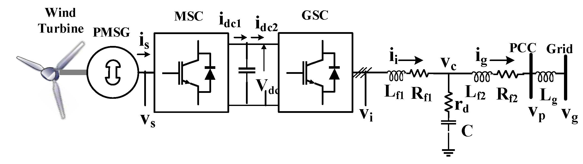
3. System Modelling and Proposed Controller Design

The MSC and the GSC of the WPS shown in Figure 1 are controlled for real power and DC-link potential regulation, respectively. To ensure the rotor speed is within its safe limit, a modified control scheme is proposed on MSC without enhancing the pitch angle control mechanism. Further to overwhelm the impacts of unsymmetrical fault, a simple power oscillation suppression scheme is offered on GSC with the existing vector control without involving in the complex computation of negative sequence current components and, in turn, the dual inner current control loops. The converter’s controller modelling is described in the following sub-sections.

3.1. Modified MSC Controller
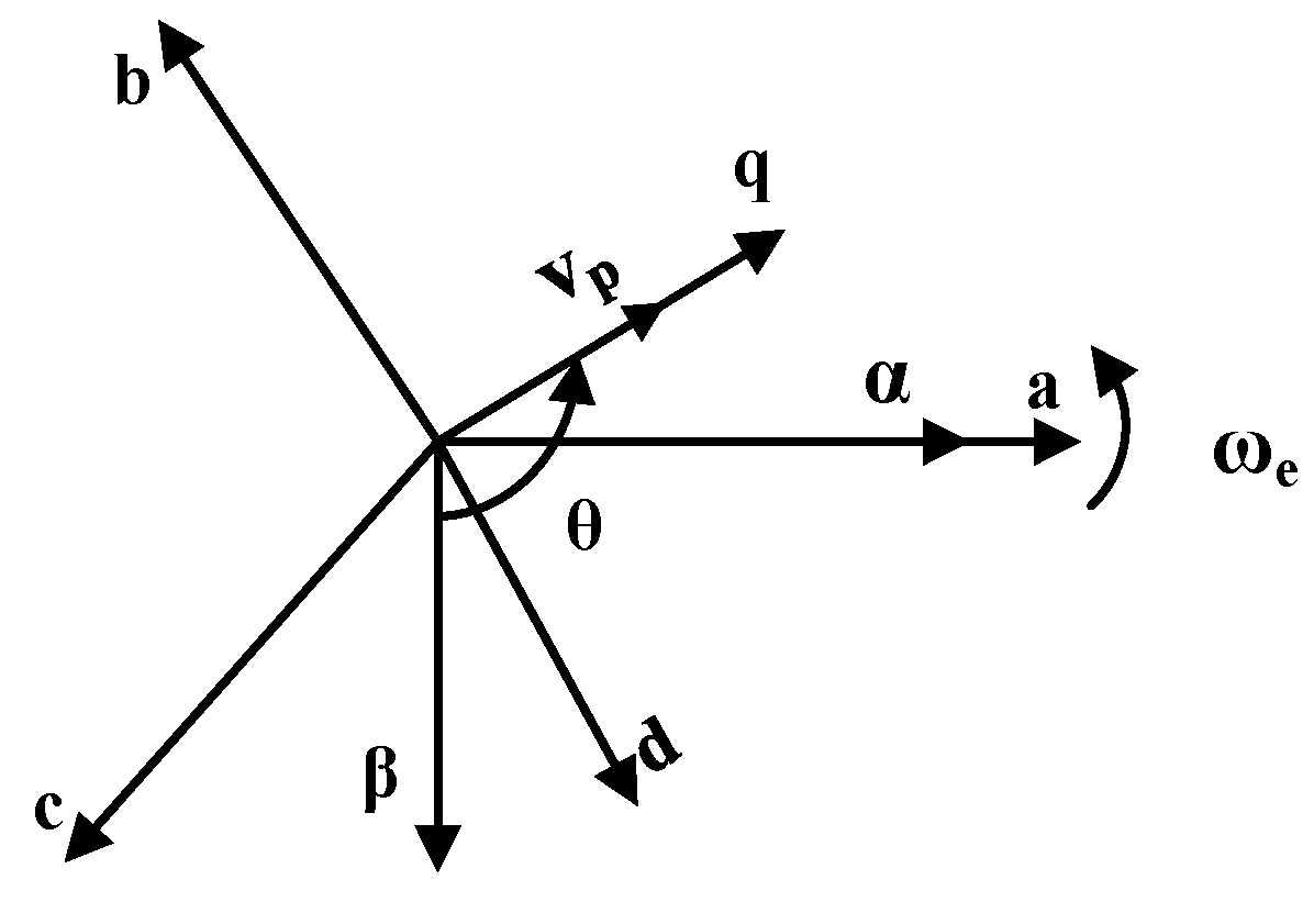
Assuming the alignment of rotor magnet along d-axis [17], the PMSG stator voltage, vs. is given as
v s d = R s i s d + L s d d i s d d t ψ q ω e s v s q = R s i s q + L s q d i s q d t + ψ P M ω e s + ψ d ω e s
where Rs, Ls, and Ψ, respectively, represent the stator resistance, current, inductance and flux linkage. ωes is the rotor angular speed in rad/s. The modified MSC controller design to emulate the pitch angle control mechanism is shown in Figure 3. Initially, the stator active current reference i*sq is derived concerning the active power reference (P*s) generation scheme, as proposed in Section 4. Upon grid fault, specifically under PLM, the reduced active power corresponds to two speeds, as depicted in Figure 3. Due to inertia, the generator settles at the speed of ω2, which may be higher than the rated speed ωR. A pitch angle control mechanism is generally employed to ensure that MSC regulates the same active power at speed ω1 rather than ω2. However, the control mechanism is quite tricky as a result of the nonlinear aerodynamic characteristics of the wind turbine. A simple and robust control scheme is proposed in this paper to regulate the reduced real power by controlling the speed of the generator. The active current reference from the outer speed regulation loop is activated when the PMSG speed is greater than the rated speed, and subsequently, the power evacuated reduces. As the speed control loop always operates at a much lower speed and continual speed transients are not involved, the strategy yields a better dynamic response. The control scheme with only a speed regulation loop with higher compensator gain value results in a deprived transient’s response for the step-change in wind velocity. The significance of the proposed MSC controller is further detailed in Section 4.

3.2. GSC Modelling

The dynamic model of the GSC with the filter impedance in the d-q frame is given as
x ˙ = A x + B u
where A, B, x and u can be correspondingly expressed as
A = R f 1 L f 1 ω e 1 L f 1 0 0 0 ω e R f 1 L f 1 0 1 L f 1 0 0 1 C 0 0 ω e 1 C 0 0 1 C ω e 0 0 1 C 0 0 1 L f 2 0 R f 2 L f 2 ω e 0 0 0 1 L f 2 ω e R f 2 L f 2 B = 1 L f 1 0 0 0 0 1 L f 1 0 0 0 0 0 0 0 0 0 0 0 0 1 L f 2 0 0 0 0 1 L f 2 x = i i d i i q v c d v c q i g d i g q ; u = v i d v i q v p d v p q
where the inductance Lf and resistance Rf with the subscript 1 and 2 represent the GSC filter impedance; ii and ig represent the GSC and grid current, respectively; vp, vc and vi, respectively, represent the PCC, AC capacitance and GSC voltage. The transformation is performed per the space vector representation of the PCC voltage shown in Figure 2. Moving averages filter (MAF) based phase-locked loop (PLL) is used to obtain the angular position θ and frequency ωe of the PCC voltage by aligning the phase voltage in q-axis [18]. The steady-state real and reactive power at the PCC under regular grid operation can be expressed as
P p = 1.5 v p q i i q + v p d i i d
Q p = 1.5 v p q i i d v p d i i q
As per the space vector representation, the steady-state d-axis voltage at the PCC is zero, and hence, the grid real and reactive power is controlled by q and d-axis GSC current, respectively.

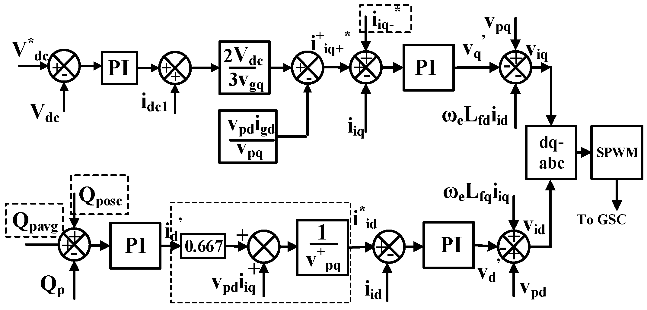
3.3. GSC Controller Design

The DC-link voltage and reactive power control are implemented on the GSC, as shown in Figure 4. Here, AC capacitor C is designed to filter the high-frequency harmonics and not as a reactive power source. Accordingly, the inner current control loop in the d-q frame is obtained by assuming ii = ig and rewriting (6) as
L f d d i i d d t + R f i i d = ω e L f d i i q + v p d v i d L f q d i i q d t + R f i i q = ω e L f q i i d + v p q v i q
where Lf = Lf1 + Lf2 and Rf = Rf1 + Rf2.
As GSC current control is adopted, the inner current control loop is framed as
s L f + R f i i d q = v d q = K p i + K i i s i i d q * i i d q
where Kpi and Kii represent the proportional and integral gain of the inner current controllers. The PI controllers output value can be expressed as
v d q = ± ω e L f i i d q + v p d q v i d q
As the GSC controller voltage is required to generate the sinusoidal pulse width modulation, the voltages vid and viq are derived to be
v i d = ω e L f i i q + v p d v d v i q = ω e L f i i d + v p q v q
As d-axis grid current is controlled for reactive power, the correlation between the inner current references i*id and outer compensator output, as given in (12) is formulated.
i d = Q p * Q p K p Q + K i Q s
where KpQ and KiQ represent the proportional and integral gain of the outer reactive power controller and using (7b) the inner current reference i*id is derived to be
i i d * = 1 v p q i d 0.667 + v p d i i q
Similarly, the active current reference i*iq is generated from the outer DC-link potential regulation loop [9], as illustrated in Figure 4. The current reference design helps to set the limits of the PI regulator at lower values rather than directly deriving the current reference from the output of the outer PI controller [20].

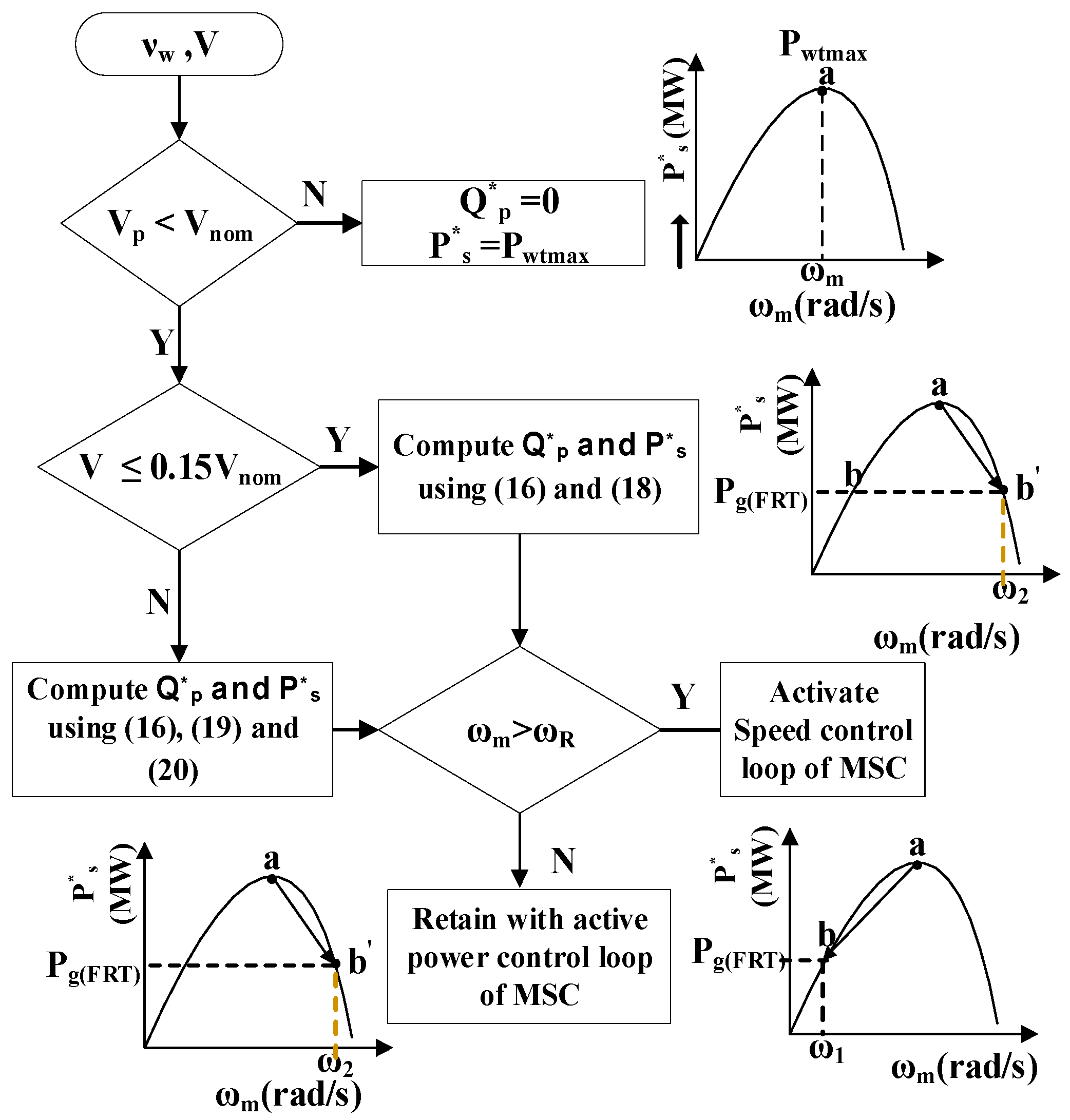
4. Proposed Reference Power Generation Scheme

A unique reference power generation scheme is proposed in this paper to address various grid disturbances and to guarantee the FRT requirements and the interconnected system stability. The reactive power reference must be a PSC with a symmetrical voltage drop to raise the PCC voltage. While with the unsymmetrical voltage drop and phase-jump and harmonics, the reactive power reference must contain both PSC and NSC to neutralize the oscillations and equalize the PCC voltage [25]. The same will hold for active power reference too. An average and oscillation power reference generation scheme is described in the following subsections to comply with the grid connectivity of IEGC [1].
A unified power reference scheme is proposed in this section to raise and balance the PCC voltage corresponding to symmetrical and unsymmetrical grid faults by operating the GSC at the constant current control mode (rated current). As the PCC voltage enhancement beyond a specific value is insignificant due to lower grid impedance [22], a reduced reactive power reference scheme is proposed based on the significant improvement in the PCC voltage instead of maximum power reference. Accordingly, to match the maximum power capability, the surplus power is set as an active power reference.

4.1. Symmetrical Voltage Sag

An average power reference is formulated based on the percentage of symmetrical voltage sag. Under regular grid operation, maximum real and zero reactive power is injected into the grid [26]. The power references under this scenario are given by
P s * = P w t ( max ) = 1 2 ρ π r 2 C p max ν 3 Q p * = 0
As stated in [21], if P*s are retained at maximum power under a grid fault, the grid current increases beyond its limit to import the same real power to the grid. Schemes are developed with different current references for different percentages of voltage sag [20]. It is inferred that the control scheme operates the GSC under a constant peak current control strategy under a higher (100–50%) percentage of voltage sag. However, for the lower (15% and below) and intermediate stages (50–15%) of voltage sag, the GSC is not operated at its total capacity, i.e., at its rated current. Moreover, the percentage improvement in PCC voltage and the corresponding amendment in grid active/reactive power have not been conveyed in the cases considered.
Furthermore, the defined active and reactive current profile may be appropriate for specific wind speeds and may not be unique for different wind speeds. As the input wind speed is not constant, available active power varies, in turn, the active current reference. Hence, for lower wind speed by retaining the respective maximum active current, excess reactive power can be delivered to the grid compared to higher wind speed. This paper proposes the power limitation scheme, so the GSC operates under rated current control mode during grid faults. Both real and reactive powers injection during the voltage sag illustrates the contribution of maximum possible reactive power for the variation in the grid voltage. It can be reduced to a significant percentage with an equivalent active power injection and vice versa under higher and lower voltage sag.

4.1.1. Maximum Power Limits

The power reference scheme accounts for the key consideration of maximum reactive and active power injection under higher and lower voltage drops. The grid voltage Vg can be estimated by measuring the PCC voltage and knowing the grid inductance and injected current [27]. With the formulated grid voltage vector, it is easy to calculate the amount of reactive power required to increase the PCC voltages to the corresponding reference values. Hence, the improvement in PCC voltage Vpi is initially determined considering the GSC rated current Ii(rated) and the grid impedance Zg as
If   V p i V p n   then   V p i = I i ( r a t e d ) Z g + V g   else   V p i = V p n
If the computed Vpi is greater than the nominal PCC voltage Vpn, then Vpi should be limited to Vpn to avoid disconnection owing to overvoltage. Correspondingly, the individual maximum reactive and active power reference is formulated as given in (16) where vpiq+ and iiq+(MPPT) represents the phase peak magnitude of improved PCC voltage and GSC maximum active current before the grid disturbance, respectively.
Q p * = Q p a v g P s * = 1.5 ( v p i q + i i q + M P P T )
Qpavg, in turn, is described as
Q p a v g = 1.5 ( v p i q + i i d + )
By referring to the computed maximum power limits, the active and reactive power reference scheme is proposed for the MSC and GSC, respectively.

4.1.2. Constant Current Control

According to the FRT requirements of IEGC [1], the power references are derived as given in (16) to operate the GSC under constant current control mode. Hence, for the percentage of voltage drop, the currents iid and iiq are updated as given below.
Under severe fault conditions of 85% voltage sag, considering the minimal speed of operation instead of zero speed, it is proposed to inject a considerable percentage of active power. In this regard, out of the maximum possible current limit, 95% of ii is set as reactive and remaining as active as given below:
i i d + = 0.95 i i ( R a t e d ) i i q + = i i ( R a t e d ) 2 i i d + 2
Furthermore, 5% of reactive power enhances the PCC voltage to a meagre value depending on the GSC filter and grid impedance. However, 5% of active power reference delivers a significant percentage of generated power to the grid. Irrespective of the wind speed (i.e., cut-in to rated speed), the aforementioned current formulae are used under this scenario.
Upon lower voltage drop, i.e., with 85% PCC voltage, the active and reactive currents are formulated in (19) and (20), respectively.
If   i i q + < 0.95 i i R a t e d   then   i i q + = i i q + M P P T elseif   0 . 95 i i R a t e d < i i q + < i i R a t e d   then   i i q + = 0.95 i i q + M P P T
i f   i i q + < 0.95 i i R a t e d   t h e n   i i d + = i i R a t e d 2 i i q + 2 e l s e i f   0 . 95 i i R a t e d < i i q + < i i R a t e d   t h e n   i i d + = i i R a t e d 2 i i q + 2
The strategy allows significant PCC voltage and active power injection improvement even under higher wind speeds. By substituting (18)–(20) in (16), the power references (P*s, Q*p) at 85% and 15% voltage sag are obtained. The overall power reference scheme during different scenarios subjected to wind velocity and grid voltage is depicted in Figure 5.

4.1.3. Rotor Speed Regulation

The power regulation during voltage sag, i.e., MPPT to PL mode, may result in rotor speed greater than the rated speed, the speed limits check and the countermeasures are also incorporated in the proposed scheme. For instance, under higher voltage sag, the reduced power corresponds to two speeds ω1 and ω2. To ensure a safer operating value, the system operates at speed ω1, if ω2 is greater than the rated speed ωR. Since grid imperfections with both PSC and NSC introduce oscillations in the system parameters, the control scheme must also be updated with oscillation neutralization as discussed in the following subsection.

4.2. Grid Imperfections with Both PSC and NSC

Likewise, in symmetrical sag, the constant current control strategy could not be implemented under unsymmetrical sag since the voltage in each phase rises equally, and the phase voltage with nominal value suffers overvoltage and leads to disconnection. Moreover, to balance the PCC voltage, the power references must be updated with both PSC and NSC rather than only PSC [25]. Moreover, the power and current reference must also be updated with the corresponding NSC. Hence, unbalanced voltage sags require a different control strategy than balanced sag; however, the speed regulation concept remains the same. In this view, the control strategy is proposed in this paper for enhanced control of PMSG, specifically under asymmetrical voltage sag, phase-jump, and harmonics. As a foremost step, the PSC of Vpi is formulated, and the computed value is used to determine the significant percentage of active and reactive power, as given in (16). The active and reactive currents are formulated as given in (21) and (22), representing the PSC to avoid overvoltage in the phase with the nominal value.
If   i i q + < 0.95 i i R a t e d   then   i i q + = i i q + ( M P P T ) elseif   0 . 95 i i R a t e d < i i q + < i i R a t e d   then   i i q + = 0 . 95 i i q + ( M P P T )  
If   i i q + 2 + i i d + 2 i i R a t e d   then   i i d + = V p i q V g q Z g elseif   0 . 95 i i R a t e d < i i q + < i i R a t e d   then   i i d + = i i R a t e d 2 i i q + 2
The active and reactive grid power NSC components are derived by expressing (7) in PSC and NSC of Vp and ii as
P p = P p + + P p ;   Q p = Q p + + Q p
where P p + = 1.5 v p d + + i i d + + + v p q + + i i q + +
Q p + = 1.5 v p q + + i i d + + v p d + + i i q + +
P p = 1.5 v p d + i i d + + v p q + i i q + + v p d + i i d + + + v p q + i i q + + + v p d + + i i d + + v p q + + i i q +
Q p = 1.5 v p q + i i d + v p d + i i q + + v p q + i i d + + v p d + i i q + + + v p q + + i i d + v p d + + i i q +
Eventually, the outer grid reactive power and inner active current reference is formulated with average PSC and NSC as
Q p * = Q p a v g + Q p
i i q * = i i q + + * + P p 0.667 v p q + i i q + +
Contrary to dual current control, a simple strategy is proposed to process the PSC and NSC using a single current loop. This is accomplished by adding the estimated NSC of Qposc and iiq- with Qpavg and iiq+, respectively, as shown in Figure 4.

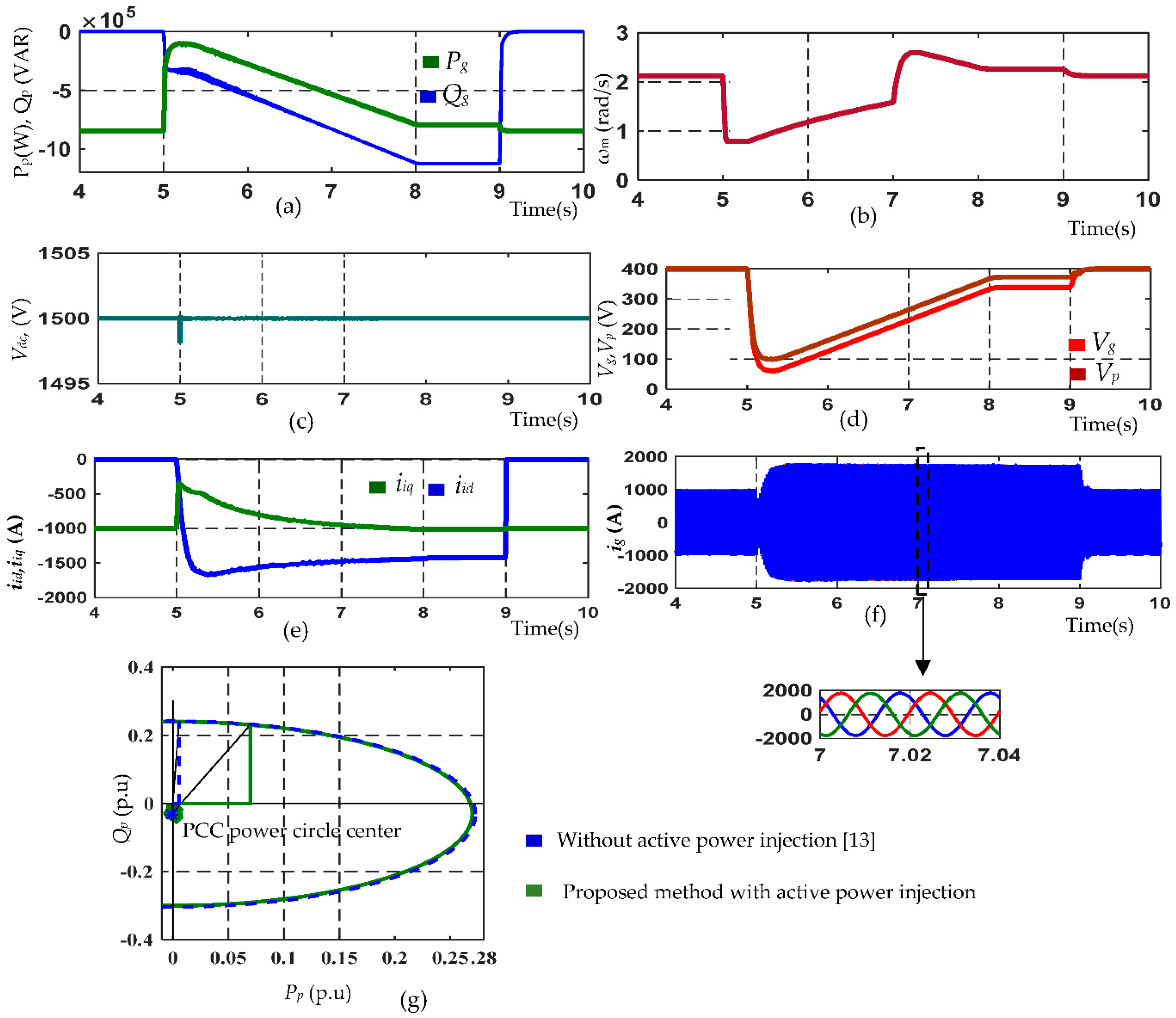
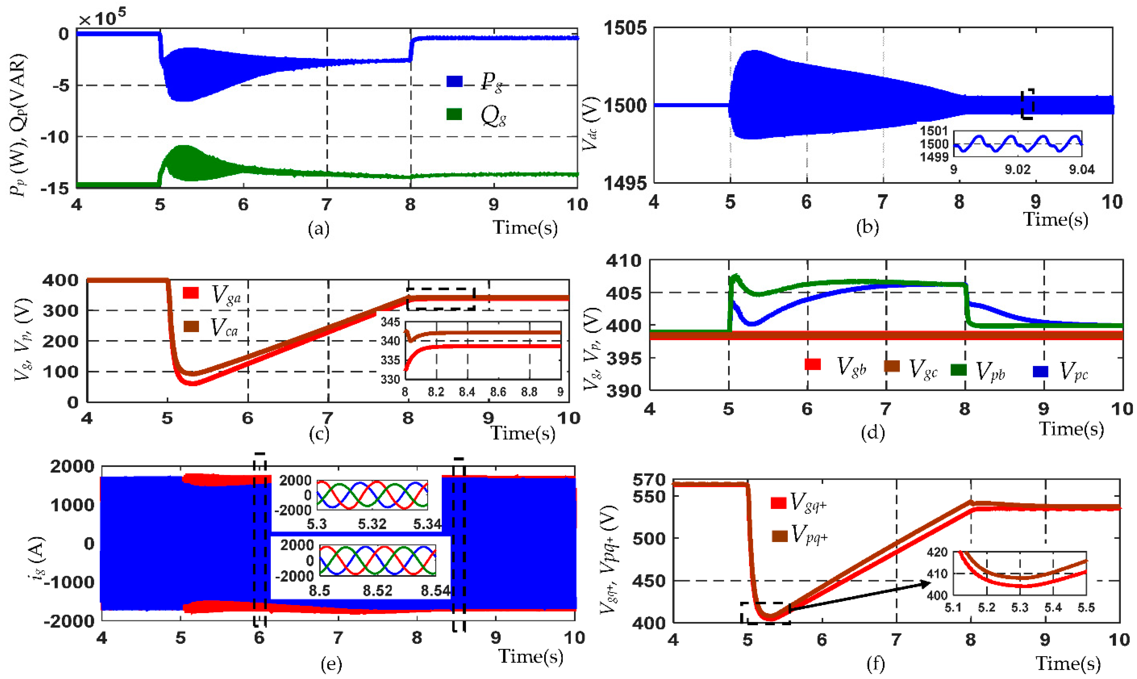
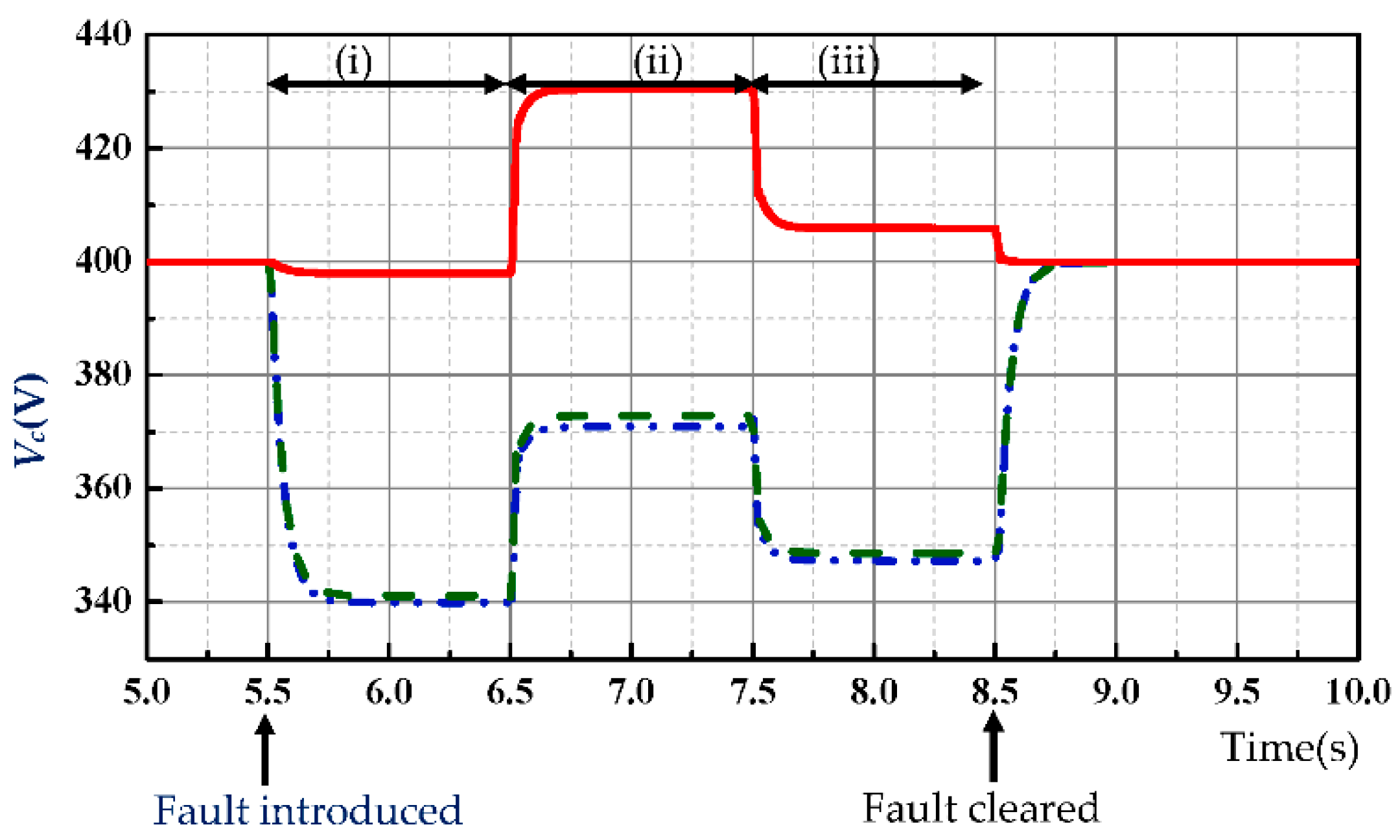
5. Simulation Validation

Analytical modelling is carried out in PSCAD/ EMTDC to verify the efficacy of the proposed control scheme for a 1.5 MW PMSG build WPS. The WPS specifications given considered for this work [16]. The effectiveness of the control scheme is validated under grid disturbances like three-phase, single-phase and two-phase faults commonly occurring at WG grid interconnection points [28]. IEGC is followed to support the FRT requirements with the proposed real and reactive power reference computation scheme. The PI controller’s gain values are formulated, as demonstrated in [29,30] with a damping ratio ϵ= 0.707.
Case 1: In this case, IEGC voltage profile is considered for testing the performance of the proposed control scheme during high to low voltage sag (symmetrical) transition for the wind velocity of 10 m/s. The fault is initiated at t = 5 s, and the voltage profile is followed till t = 8 s, from t = 8 s to t = 9 s 85% of the nominal voltage is retained and from t = 9 s onwards 100% of the grid voltage is maintained. Before a fault, i.e., from t = 0 s to t = 5 s, the real and reactive power references are set to maximum generated and zero, respectively. The PCC voltage is enhanced during the fault by injecting Q*p as illustrated in Figure 6a. Under 85% voltage sag, the reactive current reference is changed from zero to 0.95iidDC, which raises the PCC phase voltage from 59.7 V to 98.7 V by retaining the GSC current within the safe operating limits as depicted in Figure 6d,f. Figure 6b further confirms that the generator speed is settled within its limit by regulating the active power from the outer speed control loop during this scenario. Additionally, the DC-link potential is retained within its limit, as given in Figure 6c by the proposed power generation scheme. Figure 6g compares the enhancement in PCC voltage with maximum reactive power support and zero active power injection [20,31,32,33,34] and the proposed method of reactive power support with a consistent percentage of real power into the grid provided the GSC is operated under constant current control mode. It can be inferred that the maximum reactive power support and proposed scheme enhance the PCC voltage from 59.7 V to 100.2 V and 98.7 V, respectively. This scenario validates the proposed control scheme described in Section 4.1.
Case 2: Single-phase to ground fault is accounted in this case with a scenario discussed in case 1 with the wind velocity of 12 m/s. The proposed control scheme sets the PSC and NSC of power as the real and reactive power references. The performance improvement in the system parameters with the proposed control scheme is depicted in Figure 7. The real and reactive power injection at 15% voltage sag is shown in Figure 7a. During this scenario, the PCC voltage Vpa is improved to 342 V from 338 V, and Vpb and Vpc are maintained around the nominal value of 398.37 V as shown in Figure 7c,d, respectively. However, under 85% voltage sag, the PCC voltages Vpa is improved to 100.7 V from 59.7 V, whereas Vpb and Vpc are almost maintained constant as pre-fault values. Owing to the power oscillation reference scheme, the percentage oscillations in DC-link potential, real and reactive power under 15% sag is noted to be 0.04%, 0.6% and 0.46%, respectively. Additionally, a sinusoidal and symmetrical GSC current is obtained, as shown in Figure 7e. The overall improvement in PSC of Vpq is depicted in Figure 7f.
Case 3: In this case, two-phase to ground fault is considered to comply with the grid code requirements of IEGC. The effectiveness of the proposed scheme in raising and balancing the PCC voltage is illustrated in Figure 8 for the wind speed of 10 m/s. A ‘b-c’ ground fault with the voltage sag of 15% is created at t = 5.5 s, and from t = 5.5 s to 6.5 s reactive power support is not provided, and hence the PCC voltage is not enhanced. From t = 6.5 s to 7.5 s reactive power support according to the symmetrical power reference scheme is provided, which increases the non-fault phase voltage beyond the nominal value. However, the balanced power reference scheme, which is activated at t = 7.5 s to 8.5 s maintains the non-fault phase voltage closer to the nominal value and increases the faulted phase voltages. This scenario also validates the proposed scheme with different power references for symmetrical and unsymmetrical faults. The numerical illustration of the same is tabulated in Table 1 with the corresponding GSC current value. Furthermore, the proposed scheme minimizes the oscillations in DC-link potential, grid real and reactive power, and the percentage of oscillations are noted to be 0.066%, 1.68%, and 0.95%, respectively. The performance of the proposed scheme in raising and balancing the PCC voltage is also illustrated for different wind velocities, as depicted in Figure 9a. Despite this, symmetrical sinusoidal GSC current is obtained even during the fault, depicted as current circular loci, as shown in Figure 9b.

6. Conclusions

The effectiveness of the reactive power reference scheme is validated in raising and balancing the PCC voltage under symmetrical and asymmetrical faults, respectively. The corresponding real power reference further ensures a consistent percentage of active power injection into the grid without violating the system ratings. Overall, with the proposed power reference scheme, the PCC voltage is raised to 24.28% under the worst-case scenario of 85% symmetrical voltage sag. Likewise, the PCC voltage under two-phase to ground fault correspondingly at 85% and 15% sag is improved to 46.1% and 90.2% from 43.12% and 92.17%, respectively. The percentage of oscillation reduction in DC-link potential, grid real and reactive power under single-phase and two-phase to-ground faults further confirms the scheme’s efficacy.

Author Contributions

Conceptualization, V.R.; Data curation, V.R. and S.D.; Formal analysis, V.R. and S.D.; Investigation, V.R.; Methodology, V.R.; Project administration, A.S.P.; Resources, A.S.P. and P.P.; Software, A.S.P. and P.P.; Supervision, A.S.P. and N.L.; Validation, N.L.; Visualization, N.L., P.P. and S.D.; Writing—original draft, N.L.; Writing—review and editing, S.D. All authors have read and agreed to the published version of the manuscript.

Funding

This research received no external funding.

Data Availability Statement

The data presented in this study are available on request from the corresponding author.

Acknowledgments

The authors would like to thank Vellore Institute of Technology and University of Tromso for their support.

Conflicts of Interest

The authors declare no conflict of interest.

References

  1. Central Electricity Regulatory Commission. Indian Electricity Grid Code Regulations (Fourth Amendment); Ministry of Power Government of India: New Delhi, India, 2016. [Google Scholar]
  2. Central Electricity Authority (Grid Standards). Indian Electricity Grid Code Regulations 2010. The Gazette of India, 26 June 2010. [Google Scholar]
  3. Adriana, M.; Pedro, P.; João, F.M. A Survey on Power Grid Faults and Their Origins: A Contribution to Improving Power Grid Resilience. Energies 2019, 12, 4667. [Google Scholar]
  4. Bollen, M.H.J.; Olguin, G.; Martins, M. Voltage dips at the terminals of wind power installations. Wind. Energy 2005, 8, 307–318. [Google Scholar] [CrossRef]
  5. Kanasottu, A.N.; Chandra, P.G.; Eugene, F. Complying the LVRT grid code requirement of a fixed speed wind energy system using unified voltage and pitch angle control strategy. Wind. Eng. 2022. [Google Scholar] [CrossRef]
  6. Kishor, V.B.; Dipak, P.P.; Sunildatta, S.K. Grid Integration of Wind Energy Generation System and Grid Code Requirements. In Deregulated Electricity Market: The Smart Grid Perspectives, 1st ed.; CRC Press: Boca Raton, FL, USA, 2022. [Google Scholar]
  7. Amir, A.; Lorenzo, Z.; Nicolaos, A. Cutululis. Fault ride through capability of grid forming wind turbines: A comparison of three control schemes. IET Renew. Power Gener. 2022, 16, 1866–1881. [Google Scholar]
  8. Meng, Y.; Wu, K.; Jia, F.; Yan, S.; Yang, Y.; Wang, X. Grid integration and fault ride-through of fractional frequency offshore wind power system based on Y-connected modular multilevel converter. IET Gener. Transm. Distrib. 2022, 16, 2977–2988. [Google Scholar] [CrossRef]
  9. Wang, X.; Wu, H.; Wang, X.; Dall, L.; Kwon, J.B. Transient Stability Analysis of Grid-Following VSCs Considering Voltage-Dependent Current Injection during Fault Ride-Through. IEEE Trans. Energy Convers. (Early Access) 2022, 1–13. [Google Scholar] [CrossRef]
  10. Jlassi, I.; Cardoso, A.J.M. Fault-Tolerant Back-to-Back Converter for Direct-Drive PMSG Wind Turbines Using Direct Torque and Power Control Techniques. IEEE Trans. Power Elect. 2019, 34, 11215–11227. [Google Scholar]
  11. Ahmed, H.; Bhattacharya, A. PMSG-based VS-WECS for constant active power delivery to standalone load using direct matrix converter-based SST with BESS. IET Gener. Transm. Distrib. 2019, 13, 1757–1767. [Google Scholar] [CrossRef]
  12. Muyeen, S.M.; Murata, R.T.T.; Tamura, J. A Variable Speed Wind Turbine Control Strategy to Meet Wind Farm Grid Code Requirements. IEEE Trans. Power Syst. 2010, 25, 331–340. [Google Scholar] [CrossRef]
  13. Chen, C.; Liu, H.; Wu, L.; Shen, C.; Ju, Y. LVRT Test data analysis of converter interfaced wind turbines. IET J. Eng. 2019, 16, 1550–1553. [Google Scholar] [CrossRef]
  14. Li, P.; Song, Y.-D.; Li, D.-Y.; Cai, W.-C.; Zhang, K. Control and Monitoring for Grid-Friendly Wind Turbines: Research Overview and Suggested Approach. IEEE Trans. Power Electron. 2015, 30, 1979–1986. [Google Scholar] [CrossRef]
  15. Valenciaga, F.; Fernandez, R.D. Multiple-input–multiple-output High-order Sliding Mode Control for a Permanent Magnet Synchronous Generator Wind-Based System with Grid Support Capabilities. IET Renew. Power Gener. 2015, 9, 925–934. [Google Scholar] [CrossRef]
  16. Li, S.; Haskew, T.A.; Swatloski, R.P.; Gathings, W. Optimal and Direct-Current Vector Control of Direct-Driven PMSG Wind Turbines. IEEE Trans. Power Electron. 2012, 27, 2325–2336. [Google Scholar] [CrossRef]
  17. Vijayapriya, R.; Raja, P.; Selvan, M.P. A Modified Active Power Control Scheme for Enhanced Operation of PMSG Based WGs. IEEE Trans. Sust. Energy 2018, 9, 630–638. [Google Scholar]
  18. Jahanpour-Dehkordi, M.; Vaez-Zadeh, S.; Mohammadi, J. Development of a Combined Control System to Improve the Performance of a PMSG-Based Wind Energy Conversion System Under Normal and Grid Fault Conditions. IEEE Trans. Energy Conver. 2019, 34, 1287–1295. [Google Scholar] [CrossRef]
  19. Alepuz, S.; Calle, A.; Busquets-Monge, S.; Kouro, S.; Wu, B. Use of Stored Energy in PMSG Rotor Inertia for Low Voltage Ride-Through in Back-to-Back NPC Converter Based Wind Power Systems. IEEE Trans. Ind. Electron. 2013, 60, 1787–1796. [Google Scholar] [CrossRef]
  20. Yassin, H.M.; Hanafy, H.H.; Hallouda, M.M. Enhancement Low-Voltage Ride Through Capability of Permanent Magnet Synchronous Generator-Based Wind Turbines using Interval Type-2 Fuzzy Control. IET Renew. Power Gener. 2016, 10, 339–348. [Google Scholar] [CrossRef]
  21. Geng, H.; Yang, G.; Xu, D.; Wu, B. Unified Power Control for PMSG based WECS Operating under different Grid Conditions. IEEE Trans. Energy Convers. 2011, 26, 822–830. [Google Scholar] [CrossRef]
  22. Nasiri, M.; Mohammadi, R. Peak Current Limitation for Grid Side Inverter by Limited Active Power in PMSG-Based Wind Turbines During Different Grid Faults. IEEE Trans. Sust. Energy 2014, 5, 1010–1017. [Google Scholar] [CrossRef]
  23. Kim, K.H.; Jeung, Y.C.; Lee, D.C. LVRT Scheme of PMSG Wind Power Systems Based on Feedback Linearization. IEEE Trans. Power Electron. 2012, 27, 2376–2384. [Google Scholar] [CrossRef]
  24. Kim, C.; Kim, W. Enhanced Low-Voltage Ride-Through Coordinated Control for PMSG Wind Turbines and Energy Storage Systems Considering Pitch and Inertia Response. IEEE Access 2020, 8, 212558–212567. [Google Scholar] [CrossRef]
  25. Hossain, M.I.; Abido, M.A. Positive-Negative Sequence Current Controller for LVRT Improvement of Wind Farms Integrated MMC-HVDC Network. IEEE Access 2020, 8, 93314–193339. [Google Scholar] [CrossRef]
  26. Thapa, K.B.; Jayasawal, K. Pitch Control Scheme for Rapid Active Power Control of a PMSG-Based Wind Power Plant. IEEE Tran. Indus. App. 2020, 56, 6756–6766. [Google Scholar] [CrossRef]
  27. Koiwa, K.; Li, Y.; Liu, K.Z.; Zanma, T.; Tamura, J. Full Converter Control for Variable-Speed Wind Turbines Without Integral Controller or PLL. IEEE Trans. Indus. Elect. 2020, 67, 9418–9428. [Google Scholar] [CrossRef]
  28. Boldea, I. The Electric Generators Handbook: Variable Speed Generators, 2nd ed.; CRC Press: Boca Raton, FL, USA, 2016. [Google Scholar]
  29. Vijayapriya, R.; Raja, P.; Selvan, M.P. Systematized Active Power Control of PMSG-based Wind-driven Generators. IEEE Syst. J. 2020, 14, 708–717. [Google Scholar]
  30. Vijayapriya, R.; Raja, P.; Selvan, M.P. A direct analytical predetermination of PMSG based WPS steady-state values under different operating conditions. Wind. Eng. 2022, 46. [Google Scholar] [CrossRef]
  31. Robles, E.; Ceballos, S.; Pou, J.; Martın, J.L.; Zaragoza, J.; Ibanez, P. Variable-Frequency Grid-Sequence Detector Based on a Quasi-Ideal Low-Pass Filter Stage and a Phase-Locked Loop. IEEE Trans. Power Electron. 2010, 25, 2552–2563. [Google Scholar] [CrossRef] [Green Version]
  32. Camacho, A.; Castilla, M.; Miret, J.; Vasquez, J.C.; Alarcón-Gallo, E. Flexible Voltage Support Control for Three-Phase Distributed Generation Inverters Under Grid Fault. IEEE Trans. Indus. Electron. 2013, 60, 1429–1441. [Google Scholar] [CrossRef]
  33. Liu, G.; Hu, J.; Tian, G.; Xu, L. Shengtie Wang, Study on high voltage ride through control strategy of PMSG-based wind turbine generation system with SCESU. J. Eng. 2019, 17, 4257–4260. [Google Scholar] [CrossRef]
  34. Miret, J.; Camacho, A.; Castilla, M.; de Vicuña, L.G.; Matas, J. Control Scheme with Voltage Support Capability for Distributed Generation Inverters Under Voltage Sags. IEEE Trans. Power Electron. 2013, 28, 5252–5262. [Google Scholar] [CrossRef]
Figure 1. System under consideration.
Energies 15 07385 g001
Figure 2. Space vector representation of PCC voltage.
Energies 15 07385 g002
Figure 3. Modified MSC controller. ɷm—rotor speed; ɷR—rated speed; ɷ1 is the speed at P1 which is lesser than ɷR; ɷ2 is the speed at the same power P1 which is greater than ɷR.
Energies 15 07385 g003
Figure 4. Proposed GSC controller.
Energies 15 07385 g004
Figure 5. Proposed power reference scheme under symmetrical sag.
Energies 15 07385 g005
Figure 6. Performance analysis during symmetrical fault: (a) grid active (W) and reactive power (VAR); (b) PMSG speed, rad/s; (c) DC-link voltage (V), (d) PCC phase voltage (RMS), (V); (e) grid current in d-q frame, (A); (f) grid current in abc axis, A. Where the dashed square represents the zoomed-in view for the period from 7 ms to 7.04 ms; and (g) PCC end Power circle during 85% voltage sag.
Energies 15 07385 g006
Figure 7. Performance analysis during single-phase to ground fault (dashed square represents the zoomed-in view): (a) grid active (W) and reactive power (VAR); (b) DC-link voltage (V); (c) grid phase voltages (RMS), (V); (d) PCC phase voltages (RMS), (V); (e) GSC current, (A); (f) PSC of Vg and Vp (V).
Energies 15 07385 g007
Figure 8. PCC voltage enhancement during two-phase to ground fault: (i) without reactive power support; (ii) with reactive power support as described in Section 4.1; (iii) with reactive power support as defined in Section 4.2.
Energies 15 07385 g008
Figure 9. (a) grid and PCC voltage loci in the stationary reference frame, (V); (b) grid current loci in the stationary reference frame, (A).
Energies 15 07385 g009
Table 1. Performance evaluation under two-phase to ground fault.
VariablesPhase/
Components
Before Faultduring Fault
without Reactive Power Supportwith Reactive Power Support
as per Section 4.1as per Section 4.2
Vc (V)a-phase399.88339.92370.93347.29
b-phase399.88341.08372.86348.63
c-phase399.88397.9430.38405.8
PSC399.88359.6391.3367.2
Ii (A)a-phase706.2782.311155745.4
b-phase706.2806.51235.09772.89
c-phase706.2770.031134723.38
Publisher’s Note: MDPI stays neutral with regard to jurisdictional claims in published maps and institutional affiliations.

