Article

Improved-Efficacy EM-Based Antenna Miniaturization by Multi-Fidelity Simulations and Objective Function Adaptation

by
Marzieh Mahrokh
1,* and
Slawomir Koziel
1,2
1
Engineering Optimization and Modeling Center, Reykjavik University, 102 Reykjavik, Iceland
2
Faculty of Electronics, Telecommunications and Informatics, Gdańsk University of Technology, 80-233 Gdańsk, Poland
*
Author to whom correspondence should be addressed.
Energies 2022, 15(2), 403; https://doi.org/10.3390/en15020403
Submission received: 22 November 2021 / Revised: 30 December 2021 / Accepted: 5 January 2022 / Published: 6 January 2022
(This article belongs to the Special Issue RF/Microwave Circuit Design and Characterization Techniques)

Abstract

:
The growing demand for the integration of surface mount design (SMD) antennas into miniaturized electronic devices has imposed increasing limitations on the structure dimensions. Examples include embedded antennas in applications such as on-board devices, picosatellites, 5G communications, or implantable and wearable devices. The demands for size reduction while ensuring a satisfactory level of electrical and field performance can be managed through constrained numerical optimization. The reliability of optimization-based size reduction requires utilization of full-wave electromagnetic (EM) analysis, which entails significant computational costs. This can be alleviated by incorporating surrogate modeling techniques, adjoint sensitivities, or the employment of sparse sensitivity updates. An alternative is the incorporation of multi-fidelity simulation models, normally limited to two levels, low and high resolution. This paper proposes a novel algorithm for accelerated antenna miniaturization, featuring a continuous adjustment of the simulation model fidelity in the course of the optimization process. The model resolution is determined by factors related to violation of the design constraints as well as the convergence status of the algorithm. The algorithm utilizes the lowest-fidelity model for the early stages of the optimization process; it is gradually refined towards the highest-fidelity model upon approaching convergence, and the constraint violations improve towards the preset tolerance threshold. At the same time, a penalty function approach with adaptively adjusted coefficients is applied to enable the precise control of constraints, and to increase the achievable miniaturization rates. The presented procedure has been validated using five microstrip antennas, including three broadband, and two circularly polarized structures. The obtained results corroborate the relevance of the implemented mechanisms from the point of view of improving the average computational efficiency of the optimization process by 43% as compared to the single-fidelity adaptive penalty function approach. Furthermore, the presented methodology demonstrates a performance that is equivalent or even superior to its single-fidelity counterpart in terms of an average constraint violation of 0.01 dB (compared to 0.03 dB for the reference), and an average size reduction of 25% as compared to 25.6%.

1. Introduction

The emerging trends in integrated wireless communication technology require the integration of surface mount design (SMD) antennas with other on-chip system components. This, in turn, imposes miniaturization requirements in applications such internet of things (IoT), portable and implantable devices [1,2], or 5G communication systems. Several antenna size-reduction techniques involving topological alterations of the basic geometries have been proposed, including the use of corrugations in the radiator and the ground plane [3,4], the introduction of meandering slits and fractals [5], or incorporation of slots and slits [6].
The abovementioned techniques offer degrees of freedom to facilitate reaching a compromise between the compact size and the electromagnetic (EM) performance. Notwithstanding, as antenna topology evolves into more complex geometries due to topological modifications of the structure, manual or trial-and-error efforts fall short of identifying the optimum design. This shortcoming is more pronounced when multiple objectives need to be handled.
Fulfilling the stringent demands concerning the electrical and field performance of the system, along with miniaturization of the comprising structures, can be handled through constrained numerical optimization. Depending on the antenna type, specifications, and the available design database, this can be accomplished using local [7,8], quasi-global [9], or global search routines [10,11,12]. Maintaining the reliability of optimization-based antenna miniaturization requires an accurate computational model, which is most often based on full-wave EM analysis. The bottleneck is high computational cost of EM models. Numerous evaluations are required by the optimization routines, especially for complex geometries, thus this cost may become prohibitive, even in the less challenging case of local optimization, e.g., those realized using pattern search [13], or gradient-based [14,15] algorithms.
Addressing the aforementioned issues of optimization-based antenna size reduction necessitates the development of CPU-efficient numerical techniques. Based on a comprehensive analysis of the available literature, the methods used to mitigate the computational burden of EM-driven design can be categorized into two groups. The first is strictly oriented toward algorithmic improvements that primarily target faster evaluation of antenna response gradients. These include utilization of adjoint sensitivities [16,17,18,19,20,21], or the employment of sparse sensitivity updates [22]. The second group involves the utilization of surrogate modeling techniques including both data-driven [23] and physics-based models [24].
Data-driven surrogates either replace the high-cost EM simulations altogether upon initial construction, or gradually develop and train a statistical model of the system using sequential sampling techniques throughout the optimization process [25]. Examples of the modeling techniques include kriging [26], artificial neural networks [27], support vector regression [28], or fuzzy systems [29]. Unfortunately, the application of data-driven surrogates is impeded by a typically considerable nonlinearity of high-frequency system responses (sharp resonances [30]), and additionally, by the curse of dimensionality.
Physics-based surrogates typically embed problem-specific knowledge of the system at hand in an underlying low-fidelity model (equivalent networks [31], coarse-discretization EM simulations [32]). A few popular modeling techniques include feature-based optimization [33], response correction methods [34], or space mapping [35].
While global optimization routines are important in application areas such as synthesis of array antennas [36], beam-shaping and beam-steering [37], local optimization routines are employed in the majority of scenarios such as design closure (final parameter tuning), or optimization-based antenna miniaturization. This is due to the availability of reasonably good initial designs, obtained as a result of the early stages of topological developments in the antenna design process. As previously mentioned, gradient-based search routines can be greatly expedited using adjoint sensitivities. However, the availability of this technology in commercial software packages is limited. Variable-fidelity techniques including response correction methods [38,39], or space mapping [40,41], and variations thereof [42,43], can also be employed to improve the cost efficiency. Notwithstanding, the efficacy of these techniques relies on the meticulous selection of the model-fidelity and response-type dependent correction techniques [44]. Other alternatives include the employment of restricted sensitivity updates [45], incorporation of updating formulas (e.g., Broyden [9]), also in conjunction with response feature techniques [46]. These methods offer up to forty [46] or even sixty percent acceleration [47] without minor degradation of the design quality compared to that of the reference algorithms. Further benefits in terms of accelerating EM-based optimization processes can be obtained through the incorporation of multi-fidelity simulation models. They can be either incorporated into the above-mentioned sensitivity-based speedup mechanisms to boost the acceleration, or applied in the different context of expediting antenna miniaturization procedures while maintaining precise constraint control and the efficacy of the miniaturization process, which is the main focus of this paper. Nevertheless, proper management of the model fidelity is far from trivial [48].
Another issue is the efficacy of the optimization-based antenna size reduction in terms of achievable miniaturization rates. Efficient miniaturization requires explicit treatment of the antenna size as the primary objective. At the same time, satisfaction of the design constraints necessitates their appropriate handling, which is realized implicitly by means of the penalty function approach [49]. The formulation of the penalty function includes setting up the values of penalty coefficients that determine the contributions of the constraint violations to the main objective. Optimum determination thereof is a challenging task. Excessively high or low values may result in low efficacy in terms of miniaturization rates or constraint violation control. Further details of the formulation will be discussed in Section 2.1. A workaround is the adaptive adjustment of the penalty factors [50,51], which meticulously identifies the optimum setup based on the level of the constraint violations throughout the optimization process. This approach is adopted in this work as the constraint control mechanism. This paper proposes a novel procedure for accelerated miniaturization of antenna structures, incorporating variable-fidelity EM models with a continuous adjustment of the model fidelity throughout the optimization process. The model resolution is controlled by factors related to violation of the design constraints as well as the convergence status of the algorithm. The procedure utilizes the lowest-fidelity model in the early stages of the optimization process, which permits a cost-efficient exploration of the design space. The reliability is ensured by a gradual refinement of the model resolution towards the highest-fidelity model as the constraint violations are reduced beyond the preset tolerance threshold, and the optimization process approaches convergence. These mechanisms are supplemented by a penalty function approach with adaptive penalty coefficient adjustment to enable the precise control of constraints, and to achieve better miniaturization rates. The presented procedure addresses parameter tuning of the existing designs with fixed topologies, meaning the adjustment of geometry variables (antenna sizing) without changing the basic topology. The entire antenna design process, especially the development of antenna geometry, is outside the scope of this work. Our methodology was validated through miniaturization of five microstrip antennas, including two circular polarization (CP) ones, and three broadband structures. An average computational speedup of over forty percent was achieved across the benchmark set as compared to the reference algorithm, while ensuring the precise control of the constraints and improved miniaturization rates.
The originality and the technical contributions of this paper include (i) the development of a multi-fidelity model management scheme based on the design constraint violations and the convergence status of the optimization process, which permits a reliable low-cost optimization-based miniaturization of antenna structures, (ii) integration of the local gradient-based search with the multi-fidelity model management scheme as well as a penalty function approach with an adaptive penalty coefficient adjustment, and (iii) demonstration of a significant speedup in the miniaturization process that can be attained using the presented framework along with precise control over the constraint violations. The main feature that distinguishes this work from previous attempts to utilize multi-fidelity models, especially in the context of EM-driven miniaturization, is a continuous adjustment of the model fidelity based on both the convergence status and constraint violation levels. Operating over a continuous spectrum of model resolution avoids the experience-based model fidelity setup. The main advantages of this approach include a considerable speedup of the miniaturization process along with precise constraint control, along with improved quality of miniaturization as compared to the single-fidelity adaptive penalty function approach. According to the authors’ knowledge, the presented methodology is the first rigorous approach to simulation-based size reduction that integrates model resolution and constraint management schemes into a single algorithmic framework. The remaining part of the paper is organized as follows. Section 2 discusses the details of EM-based antenna miniaturization and the underlying mechanisms, which include the penalty function approach (Section 2.1), trust-region algorithm (Section 2.2), adaptive penalty coefficient approach (Section 2.3), variable-fidelity model management (Section 2.4), and finally, the proposed constraint–convergence-based procedure is discussed in Section 2.5 and Section 2.6. Section 3 provides the numerical validation of the proposed optimization frameworks, including a description of the benchmark antenna structures, the experimental setup, results and their discussion. Section 4 concludes the paper.

2. Accelerated Antenna Miniaturization by Model Fidelity and Constraint Management

This section introduces the proposed procedure for accelerated miniaturization of antenna structures, involving multi-fidelity simulation models and penalty functions with adaptive coefficient adjustment. The methodology presented here is based on two earlier works: accelerating EM-driven design through multi-fidelity model simulations [52] and the adaptive penalty function approach [50]. The incorporation thereof leads to results that were unattainable by any other method currently available. Utilization of the multi-fidelity models is widespread in high-frequency CAD (as elaborated on in Section 1). However, it has never been used in the context of constrained size reduction. In other words, we exploit this specific algorithmic tool and incorporate it into our algorithm to achieve further computational benefits. Additionally, the multi-fidelity scheme is adopted for our particular setup where the fidelity level is controlled based on the factors related to the feasibility status as well as the convergence status of the algorithm. The adjustment of the model fidelity based on the feasibility status is a novel concept and is used for the first time. This particular setup is different than the one in the prior work.
The optimization engine is a trust-region-based algorithm. A continuous adjustment of the EM analysis fidelity is realized by altering the model resolution based on factors related to the constraint violations and the convergence status of the algorithm. Utilization of the lowest-fidelity model in the initial stages of the optimization process enables a fast exploration of the parameter space. Reliability is ensured by gradually refining the model resolution towards the final stages of the optimization process. This section starts by recalling a formulation of the EM-based antenna miniaturization task using fixed penalty coefficients (Section 2.1). Antenna miniaturization with adaptive penalty coefficients is outlined in Section 2.2. Section 2.3 discusses the standard trust-region gradient-based procedure as the main optimization engine. Section 2.4 elaborates on multi-fidelity EM models, whereas Section 2.5 and Section 2.6 formulate the operating flow for the complete size reduction procedure.

2.1. EM-Based Antenna Miniaturization with Penalty Functions

We will use R(x) to designate the response of the EM simulation model of the antenna structure of interest. Here, x denotes a vector of geometry parameters to be adjusted throughout the optimization process. The miniaturization problem at hand is to minimize the antenna size A(x), subject to constraints related to the electrical and field performance. The constraints are defined as
sj(x) ≤ Sj, j = 1, …, k
where sj(x) is a scalar function representing a given figure of interest (e.g., maximum in-band reflection over a frequency range of interest), whereas Sj is a user-defined acceptance threshold.
Evaluation of sj(x) is computationally expensive as it requires EM simulation of the antenna. The penalty function approach [49] facilitates constraint handling by turning the problem into an unconstrained one. This is achieved by supplementing the objective function UA (here, corresponding to antenna size minimization) with a linear combination of penalty functions cj (j = 1, …, k) quantifying constraint violations. We have
U A ( R ( x ) ) = A ( x ) + β 1 c 1 ( x ) 2 + + β k c k ( x ) 2
In this work, relative penalty functions are employed
cj(x) = max{ζj/Sj, 0}
ζj = sj(x) − Sj
stands for absolute violations. Note that (3) ensures that the contribution of cj is non-zero only if violation of the jth constraint occurs. The corresponding penalty coefficient ¦Âj determines the proportion of the aforementioned contribution to (2).
The size reduction task is formulated as
x * = arg min x X U A ( R ( x ) )
The solution to problem (5) is subject to constraints (1). The parameter space X is determined by the lower and upper bounds for geometry parameters (entries of vector x).

2.2. Trust-Region Gradient-Based Algorithm

The optimization framework proposed in this paper builds on the standard trust-region (TR) gradient-based algorithm [53]. It solves problem (4) iteratively by generating approximations x(i), i = 0, 1, …, to the optimum solution x* through constrained optimization of a first-order Taylor approximation model L(i) of the antenna responses R(x). We have
x ( i + 1 ) = arg min x ; x ( i ) δ x x ( i ) + δ U A ( L ( i ) ( x ) ) ,   i = 0 ,   1 ,    
Note that the solution of (5) is constrained to the interval [x(i+1)δ(i), x(i+1) + δ(i)], referred to as the trust region. This arrangement accounts for different ranges of the geometry parameters. The new design x(i+1) is only accepted if UA(R(x(i+1))) < UA(R(x(i))), i.e., the objective function is improved. Otherwise, the TR size vector δ(i) is reduced [53] and the current iteration is repeated. The procedure is terminated if ||δ(i)|| is reduced below a preset limit δTR, or if ||x(i+1)x(i)|| ≤ δarg (convergence in argument).

2.3. EM-Based Antenna Miniaturization and Adaptive Penalty Coefficients

As discussed in Section 2.1, the penalty function approach offers a convenient way of handling constraints. At the same time, the efficacy of the optimization process relies upon a proper adjustment of the penalty factors βj. A workaround is the adaptive adjustment of the penalty factors [49,50], which eliminates the costly stage of trial-and-error-based penalty term setup. Additionally, adaptive adjustment allows for the precise control of the constraints, which leads to improved size-reduction rates [49]. This technique is incorporated into the optimization framework proposed in this work. The formulation of adaptive penalty factor adjustment is based upon the concepts of constraint violation as in (3), as well as sufficient constraint violation improvement defined as
Δj = j
where ζj is the absolute constraint violation, cf. (3), whereas 0 ≤ M ≤ 1 is the improvement factor; here, it is set to 0.5 as recommended in [49].
The adjustment of the penalty factor βj is governed by the following rules:
  • if x(i+1) produced in the ith iteration of (5) is infeasible from the point of view of the jth constraint but constraint violation is improved by at least Δj w.r.t x(i), ¦Âj is kept intact;
  • if x(i+1) is feasible w.r.t. the jth constraint, βj is reduced;
  • if x(i+1) is infeasible w.r.t the jth constraint and there is either insufficient improvement or no improvement in the constraint violation, βj is increased.
The quantification details concerning penalty factor decrease/increase can be found in [49].

2.4. Multi-Fidelity EM Simulation Models

Section 2.3 addressed the issue of efficient handling of design constraints, which is of primary importance for ensuring the reliability aspects of the optimization process. Another issue is its computational cost. In this paper, in order to expedite size reduction while retaining generality, we employed variable resolution EM simulations. Reducing the fidelity level of the structure results in a faster analysis at the expense of certain accuracy loss. Because they share the same underlying physics, coarse discretization models are normally well correlated with their high-fidelity counterparts, which has been widely explored in the literature to speed up optimization processes [32]. An alternative is utilization of simplified-physics representations, e.g., equivalent networks [31] or even analytical models. Yet, to specifically address antennas, reducing the resolution of EM analysis is the only universal option [32]. Regardless of the low-fidelity model origin, only two resolution levels are typically used [54]. The low-fidelity model is typically refined by using an appropriate response-type dependent correction technique [44], and it is employed as a substitute to the high-fidelity model. Popular approaches of this class include response correction methods [34] or space mapping [35]. Low-fidelity models can also offer a cost-efficient initial exploration of the design space within variable-fidelity modeling techniques (co-kriging [55]) or machine learning frameworks [56]. Notwithstanding, the reliability and the efficacy of these techniques rely on the meticulous selection of the model-fidelity [44].
Figure 1 illustrates the geometry of a circular polarization antenna along with its reflection and axial ratio responses for various fidelity levels. The dimensions of the antenna are as given in Table 1. The model resolution is adjusted using a lines per wavelength (LPW) parameter in the mesh properties setup, thus controlling the discretization density of the structure in the Time Domain Solver of CST Microwave Studio. The LPW parameter is adjusted according to the strategy described in Section 2.4, and the evaluation time corresponding to each LPW is accounted for while computing the overall CPU cost of the optimization process. The required range of LPWs is defined in the code as discrete values. They are communicated to CST through a MATLAB-CST socket one at a time. The socket actually connects the code to the CST environment. Figure 1b shows a relationship between model fidelity and the simulation time.
Note that relaxing the accuracy criteria to the lowest usable level reduces the antenna evaluation time by a factor of about three. Although the accuracy is compromised when reducing model resolution, the lower-fidelity model still preserves the overall response shape. Therefore, it can be successfully used for initial design space exploration in the antenna miniaturization process.
The lowest practical LPW denoted by Fmin can be established by inspecting the antenna responses for various fidelity levels. Similarly, the highest LPW (denoted by Fmax) corresponds to the high-fidelity model, which renders the system characteristics with sufficient accuracy. In this work, the objective is to accelerate the size reduction process by continuous control of the model fidelity within the range Fmin ≤ F ≤ Fmax. The following section provides a description of a set of prerequisites based on which the model-fidelity adjustment scheme was developed.

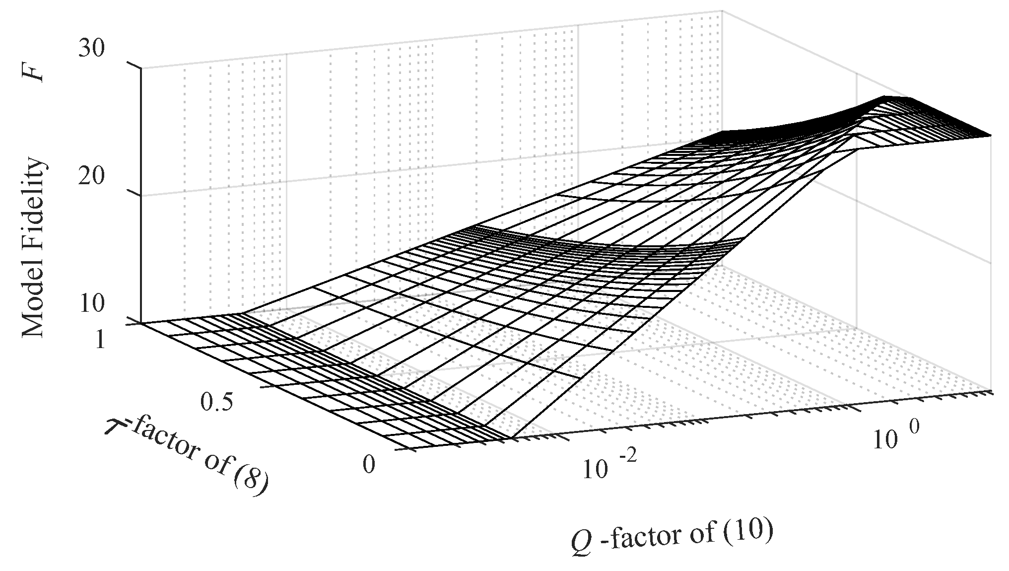
2.5. Constraint–Convergence-Based Model Management

The model management scheme employed in this work seeks to control the fidelity level of the EM simulation model throughout the optimization process. The trust-region procedure of Section 2.2 is employed as the main optimization engine. The fidelity level, represented here using a parameter F, is adjusted within the range Fmin ≤ F ≤ Fmax as defined in Section 2.4. The decision concerning the value of F is based upon a set of prerequisites as follows (see also Figure 2):
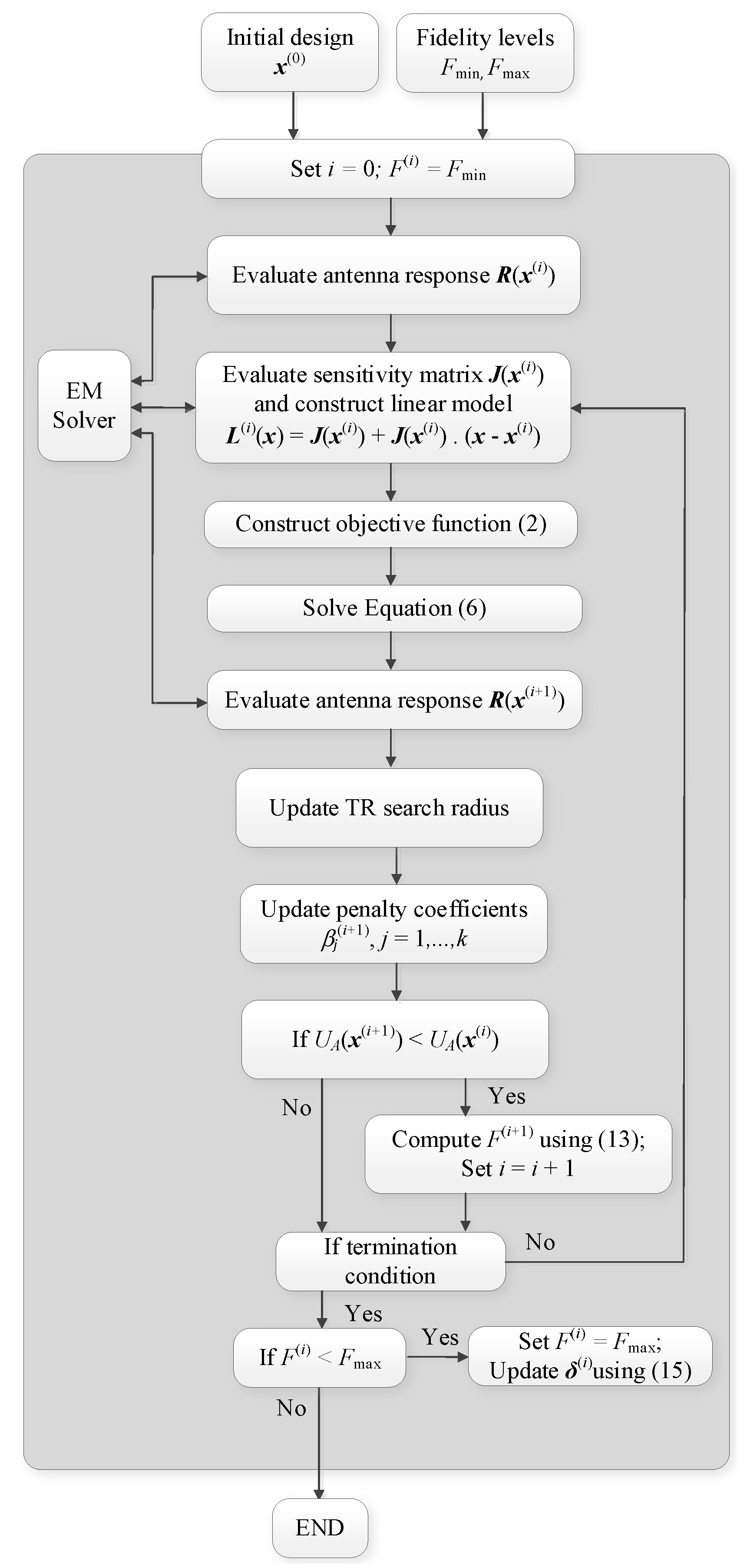
  • Fidelity level is set to the lowest value Fmin in the early stages of the optimization process (away from convergence). The decision is made regardless of the feasibility status of the solution. This permits a cost-efficient initial search within the design space;
  • Fidelity is set to the highest value Fmax upon convergence. This allows to ensure reliability of the final solution;
  • Fidelity selection in the transition phase, either from infeasible to feasible, or approaching convergence, is based upon both the feasibility status of the solution (to be formulated later), and the convergence status of the procedure;
  • The fidelity is selected from a continuous range of F-values, which improves the stability of the procedure. In particular, it allows for a smooth transition between model fidelities throughout the optimization process.
The feasibility status is quantified using an exponential function eτ(i), with τ(i) being the aggregated constraint violation at the ith iteration, defined as
τ(i) = max{j = 1, …, k: τj(i)},
where
τj(i) = ζjcj
The normalization factors τcj are selected to have τj(i) equal to unity when constraint violation reaches a user-defined threshold, which is constraint-specific. In our numerical experiments, this threshold is set to 2 dB for reflection-related constraint and 1 dB for axial-ratio-related one, cf. Section 3.
The convergence status is quantified based on two convergence criteria, namely, the distance between consecutive vectors ||x(i+1)x(i)|| ≤ δarg, and the difference between consecutive objective function values |UA(R(x(i+1))) – UA(R(x(i)))| ≤ δobj, where δarg and δobj are the respective termination thresholds. We define
Q ( i ) ( δ a r g , δ o b j ) = max { C a r g , C o b j }
where Carg and Cobj represent relative convergence factors, computed as
C a r g = δ a r g | | x ( i + 1 ) x ( i ) | |
and
C o b j = δ o b j | U A ( R ( x ( i + 1 ) ) ) U A ( R ( x ( i ) ) ) |
The model fidelity adjustment rules have been implemented in the form of the updating formula
F ( i + 1 ) = { F min   if   Q ( i ) ( δ a r g , δ o b j ) δ t h max { F ( i ) , F min + ( F max F min ) e τ ( i ) Q L ( i ) } otherwise
where F(i) is model fidelity at the ith iteration of the optimization process, and δth is a threshold for initiating an increase in model fidelity. In (13), QL(i) is the aggregated convergence status defined as
Q L ( i ) = [ 1 log ( Q ( i ) ( δ a r g , δ o b j ) ) log δ t h ]
Note that QL(i) changes between zero (for Q(i) equal to δth) and one (upon algorithm convergence, i.e., when Q(i) reaches a unity), which enables model fidelity adjustment between Fmin and Fmax. Notwithstanding, formulation (14) does not account for an unexpected termination of the algorithm without reaching the high-fidelity discretization level. This may occur due to a reduction in the TR search radius below the termination thresholds. A workaround is an additional termination mechanism as suggested in [51]. Therein, the TR search radius δ(i) is forcefully increased upon the convergence of the algorithm to
δ ( i + 1 ) = M δ δ ( i ) δ a r g | | δ ( i ) | |
whereas the fidelity level is set to the highest value, F(i+1) = Fmax. This allows for finalizing the search process at the high-fidelity level, thereby ensuring reliability.
Figure 3 visualizes the dependence between the simulation model fidelity and the convergence status Q, as well as the aggregated constraint violation τ. The said dependence is monotonic with respect to both control factors, except from the early stages of the algorithm and when close to convergence.

2.6. Proposed Miniaturization Procedure

The proposed expedited miniaturization algorithm combines the constraint–convergence-based model adjustment process of Section 2.5 and the adaptive penalty factor adjustment of Section 2.3.
The control parameters include:
  • δarg, δobj, δTR—termination thresholds (cf. Section 2.2 and Section 2.5);
  • δth—a threshold used to initiate an increase in the model fidelity (cf. Section 2.5);
  • M—sufficient constraint violation improvement factor (cf. Section 3.3);
  • Mδ—a multiplication factor used to increase the TR search radius in (15) (upon convergence);
  • τcj—constraint violation normalization factors in (8).
The termination thresholds are set to δarg = δobj = δTR = 10−3, which corresponds to a typically expected optimization process resolution, whereas the TR search region multiplication factor is selected as Mδ = 10, as suggested in [51]. The values for other control parameters are as mentioned in the previous sections. Additionally, for any given antenna structure under design, a grid convergence study is conducted to determine the values of the lowest-fidelity model Fmin, and the high-fidelity model Fmax.
As mentioned earlier, the threshold value δth is used discriminate whether the optimization process is away from the convergence or in the transition phase to convergence, which corresponds to an increase in model fidelity.
Figure 4 provides a pseudocode of the algorithm. Steps 1 and 2 set the required values for the control parameters of the algorithm to initialize the miniaturization process. In Step 3, antenna response R(x(i)) is acquired at the current fidelity level F(i). Step 4 uses finite differentiation to evaluate antenna sensitivity matrix J(x(i)) at F(i). In Step 5, a linear approximation model of antenna responses L(i)(x) at the current design vector x(i) is identified, whereas in Step 6, the objective function UA(L(i)(x)) is constructed based on the linear approximation of antenna responses. The candidate design is found in Step 7 by minimizing UA(L(i)(x)). The antenna responses and the objective function at the new design x(i+1), R(x(i+1)) and UA(x(i+1)) are evaluated in Steps 8 and 9, respectively. The TR search radius is updated in Step 10 (cf. [53]), whereas adaptive adjustment of the penalty coefficients is conducted in Step 11 [51]. Steps 12 determines whether to accept or reject x(i+1). If it is accepted, the new model-fidelity F(i+1) is computed using (13). Subsequently, the termination conditions are checked in Step 13. If the algorithm converges while the model fidelity has not reached its maximum value, we set F(i) = Fmax, and the TR search radius is increased using (15). For additional explanation, Figure 5 provides a block-diagram illustration of the algorithm operation.
The algorithm is implemented in the MATLAB programming environment. The antenna models are simulated in the time-domain solver of CST Microwave Studio. A Visual-Basic-based MATLAB-CST socket is used to connect the algorithm to CST. The new design vector produced by the algorithm is submitted to CST through this socket. The antenna model is updated accordingly, and the responses are evaluated by the CST solver. Subsequently, the aforementioned responses are post-processed in MATLAB. This procedure continues until the convergence of the algorithm.

3. Verification Examples

This section provides numerical results of the proposed procedure conducted on five verification case studies. These include five benchmark structures optimized for minimum size. The benchmark structures include three broadband antennas with a single constraint defined as maximum in-band reflection coefficient. The other two structures are CP antennas with two constraints, maximum in-band reflection coefficient, and axial ratio response. The optimization results of the proposed miniaturization procedure with constraint-convergence-based model management scheme is compared to those of the benchmark algorithm incorporating a single-fidelity adaptive penalty-factor procedure.
The remaining part of this section is organized as follows. Section 3.1 provides a description of the benchmark antenna structures. Section 3.2 includes the experimental setup of the algorithm. Numerical results and their discussion are discussed in Section 3.3 and Section 3.4, respectively.

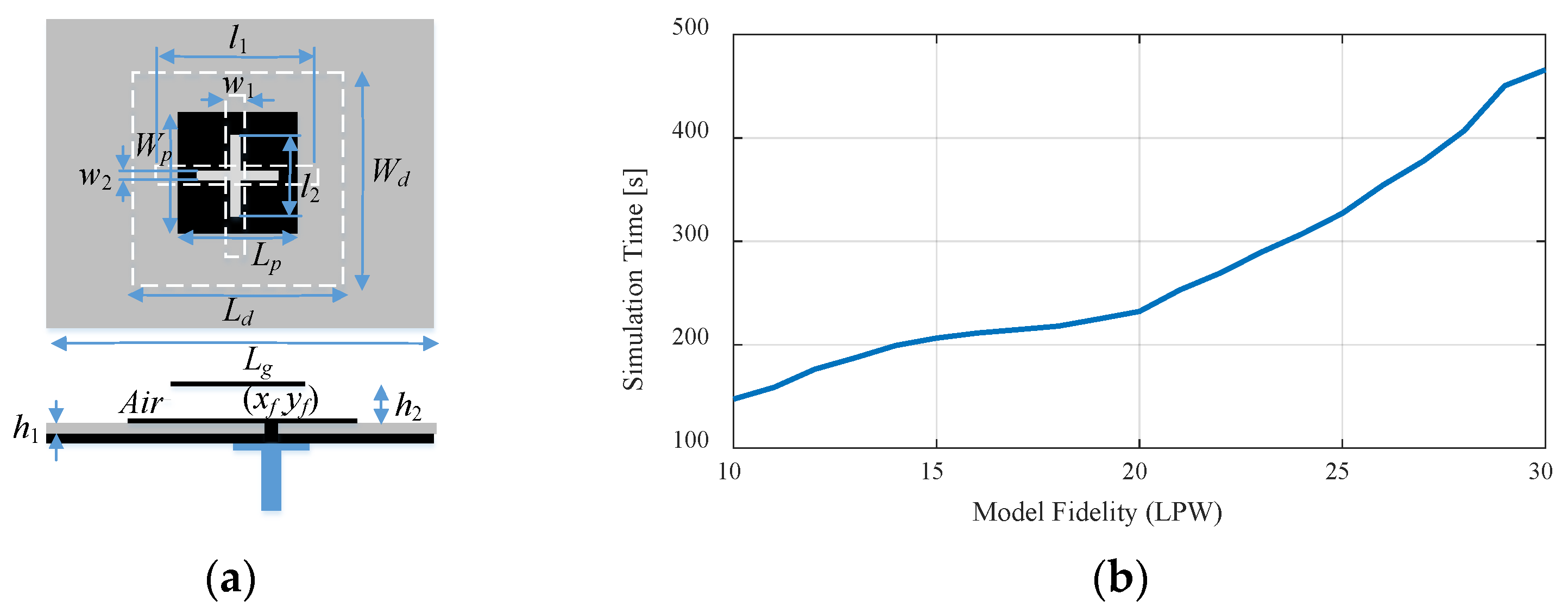
3.1. Benchmark Antenna Structures

Figure 6 shows the verification antenna structures considered in this work. These include:
  • A monopole antenna with L-shaped ground plane stub [57], Antenna I;
  • A monopole antenna with a radiator slot and modified ground plane [58], Antenna II;
  • A monopole antenna with two radiator slots and elliptical ground plane slit [59], Antenna III;
  • A stacked circular polarization antenna with circular and annular slots [60], Antenna IV;
  • A stacked circular polarization antenna with a cross-shaped radiator slot [61], Antenna V.
The relevant data for all structures is shown in Table 1. This includes the target operating bandwidths as well as design constraints. The reflection constraints are set to |S11| ≤ –10 dB for all considered examples, which is a standard threshold commonly used in antenna design tasks. However, the presented method is generic and allows for setting up any limit as required by the user (cf. Sj in Equation (1)). Table 2 provides information about the simulation times associated with the lowest-fidelity model Fmin, and the high-fidelity model Fmax for Antennas I–V. As mentioned before, these levels were decided upon through grid convergence studies (cf. Section 2.6).

3.2. Experimental Setup

The performance of the proposed procedure was evaluated by carrying out size reduction under the constraints listed in Table 1. The starting points were selected to be feasible for all antennas. This demonstrates that in all cases, there is a margin for size reduction as minimum-size designs are always allocated at the feasible region boundary.
As the primary contribution of this work is the incorporation of variable-fidelity models, the benchmark procedure is the algorithm employing the adaptively adjusted penalty coefficient scheme using a single (high-fidelity) EM model. The performance figures of interest include the antenna size, the levels of constraint violations, and the CPU cost of the optimization process. The latter is expressed in (i) absolute CPU time in hours, (ii) relative cost expressed in terms of the number of equivalent high-fidelity model evaluations, and (iii) relative computational savings enabled by the proposed algorithm as compared to the benchmark algorithm.

3.3. Result

Table 3 provides a comparison of the performance of the proposed and the benchmark procedure. As mentioned before, the performance figures include antenna size, constraint violation levels, and the computational cost of the optimization process. Figure 7, Figure 8, Figure 9, Figure 10 and Figure 11 show—for Antennas I through V—the reflection responses at the initial and the optimized designs, along with the evolution of the model fidelity in the course of the algorithm run.

3.4. Discussion

The numerical results lead to several conclusions concerning the efficacy of the proposed miniaturization algorithm incorporating the variable-fidelity EM model management scheme, and the adaptive penalty function approach. These can be briefly characterized as follows:
  • The proposed variable-fidelity procedure allows for a considerable acceleration of the miniaturization process as compared to the single-fidelity adaptive penalty function approach, by about 28 to 53 percent and by 43 percent on average.
  • The designs rendered by the proposed procedure are of a quality comparable to that produced by the single-fidelity procedure, both in terms of constraint satisfaction and achievable size reduction rates. For Antennas I–V, all constraint violations are kept at the same level of 0.0 dB, whereas the achieved antenna footprint area is smaller by 9 mm2, larger by 8 mm2, larger by 1 mm2, degraded by 25 mm2, and smaller by about 5 mm2, respectively. In practical terms, these differences can be considered minor.
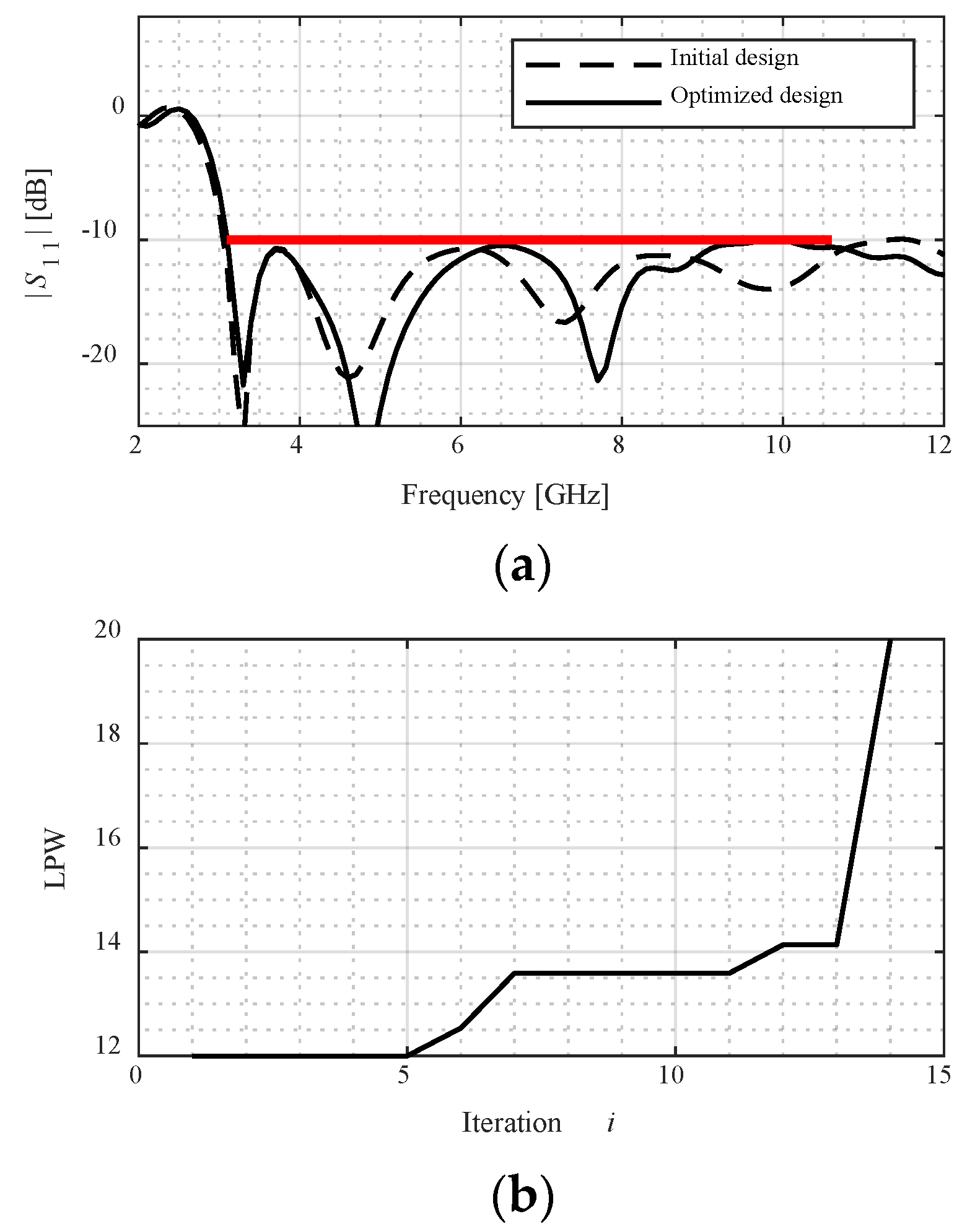
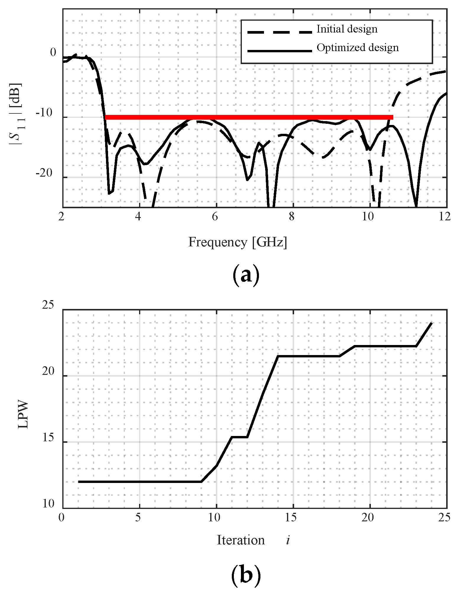
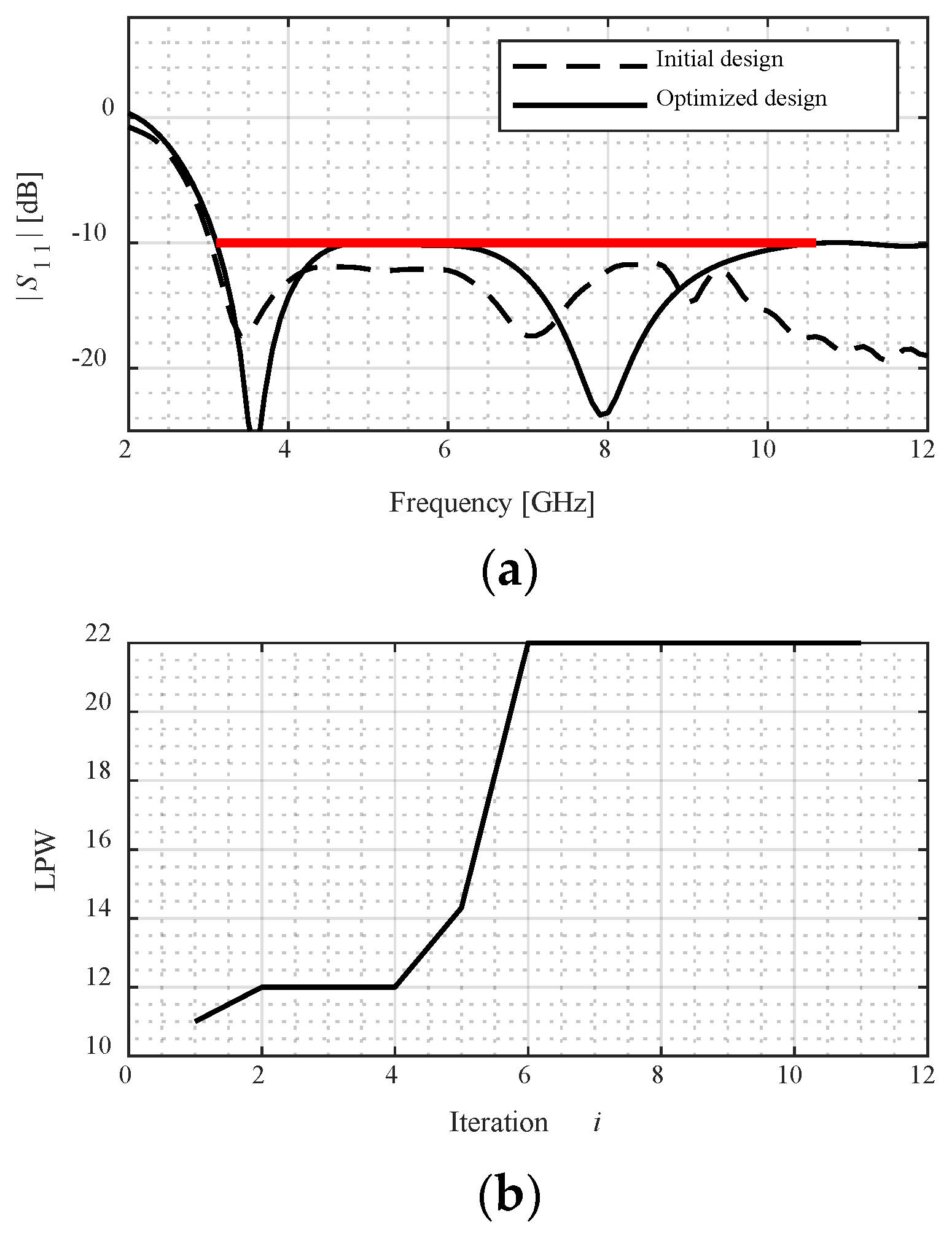
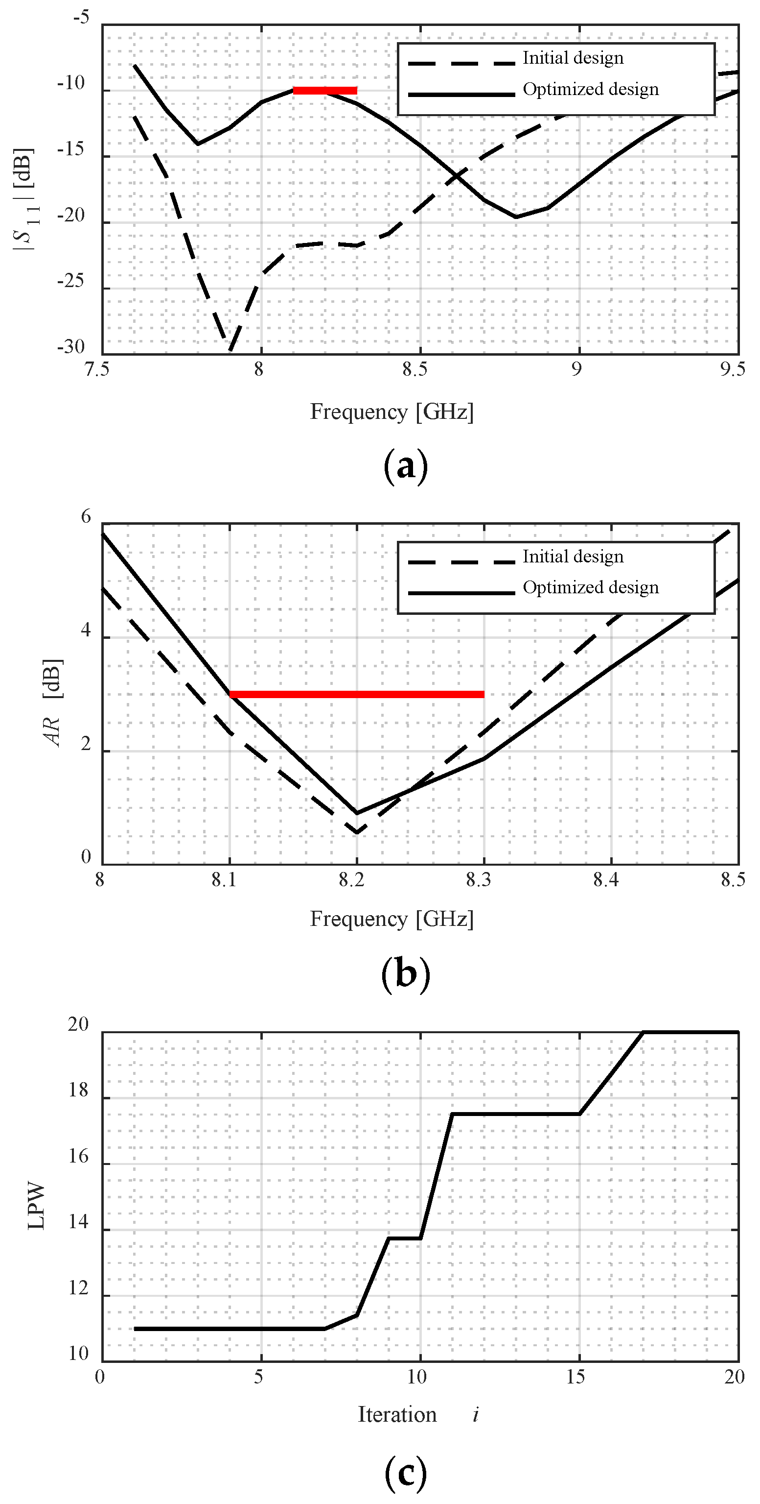
  • The reliability of the miniaturization process is ensured by conducting the final iterations of the optimization process at the level of a high-fidelity model, which gives an accurate account of antenna characteristics. This can be observed in the plots showing the evolution of the model fidelity, as included in Figure 7, Figure 8, Figure 9, Figure 10 and Figure 11. As can be observed in Figure 7, the initial design is allocated in the feasible region to demonstrate the margin for size reduction. It can be seen that the design moves towards the boundary of the feasible region as the final allocation of the optimized design, at which the reflection constraint is active. Figure 7b shows the evolution of the model fidelity across the iterations of the optimization process. It is set to the lowest value in the first few iterations, as the algorithm is away from convergence. There is a gradual increase in the model fidelity between iterations 5 and 13, corresponding to the transition phase either from infeasible to feasible, or due to approaching convergence. This increase is based on the feasibility and the convergence status of the optimization process as formulated in (13). The model fidelity is set to the highest level at the last iteration of the optimization process, when approaching convergence.
In brief, the proposed variable-fidelity miniaturization procedure demonstrably yields significant CPU time savings, while producing designs that are of comparable quality to those obtained with the single-fidelity adaptive penalty function approach. Further acceleration can be realized by the incorporation of sparse sensitivity updates [22], which will be a part of our future work.

4. Conclusions

This paper proposes a novel procedure for expedited EM-driven miniaturization of antenna structures. Our methodology incorporates a constraint-violation and convergence-based model management, combined with the adaptive penalty function procedure. The model fidelity is continuously adjusted using the control factors related to violation of the design constraints as well as the convergence status of the algorithm. The proposed procedure enables a cost-efficient exploration of the design space by utilizing the lowest-fidelity level at the early stages of the optimization process. The model-fidelity is gradually refined towards the highest-fidelity level in the final stages of the optimization process. Comprehensive numerical verification involving five microstrip antenna structures demonstrated the advantages of the presented approach, primarily a considerable speedup of the optimization process. The average computational savings are as high as 43 percent with respect to the benchmark algorithm. At the same time, no quality degradation was observed. Our future work will focus on the development and incorporation of further acceleration mechanisms, including sparse sensitivity updates, as well as dimensionality reduction methods.

Author Contributions

Conceptualization, M.M. and S.K.; methodology, M.M. and S.K.; software, M.M.; validation, M.M.; formal analysis, S.K.; investigation, M.M.; resources, S.K.; data curation, M.M.; writing—original draft preparation, M.M. and S.K.; writing—review and editing, M.M. and S.K.; visualization, M.M.; supervision, S.K.; project administration, S.K.; funding acquisition, S.K. All authors have read and agreed to the published version of the manuscript.

Funding

This work was supported in part by the Icelandic Centre for Research (RANNIS) Grant 217771, and by National Science Centre of Poland Grant 2020/37/B/ST7/01448.

Institutional Review Board Statement

Not applicable.

Informed Consent Statement

Not applicable.

Acknowledgments

The authors thank Dassault Systemes, France, for making CST Microwave Studio available.

Conflicts of Interest

The authors declare no conflict of interest. The funders had no role in the design of the study; in the collection, analyses, or interpretation of data; in the writing of the manuscript, or in the decision to publish the results.

References

  1. Le, T.T.; Yun, T.-Y. Miniaturization of a dual band wearable antenna for dual-band WBAN applications. IEEE Trans. Antennas Propag. 2020, 19, 1452–1456. [Google Scholar] [CrossRef]
  2. Agneessens, S.; Rogier, H. Compact half diamond dual-band textile HMSIW on-body antenna. IEEE Trans. Antennas Propag. 2014, 62, 2374–2381. [Google Scholar] [CrossRef] [Green Version]
  3. Abbosh, A.M. Miniaturized microstrip-fed tapered-slot antenna with altrawideband performance. IEEE Antennas Wirel. Propag. Lett. 2009, 8, 690–692. [Google Scholar] [CrossRef] [Green Version]
  4. Abbosh, A.M. Miniaturization of planar ultrawideband antenna via corrugation. IEEE Antennas Wirel. Propag. Lett. 2008, 7, 685–688. [Google Scholar] [CrossRef]
  5. Arif, A.; Zubair, M.; Ali, M.; Khan, M.U.; Mehmood, M.Q. A compact, low-profile fractal antenna for wearable on-bode WBAN applications. IEEE Antennas Wirel. Propag. Lett. 2019, 18, 981–985. [Google Scholar] [CrossRef]
  6. Yand, Y.; Zhao, Z.; Ding, X.; Nie, Z.; Liu, Q. Compact UWB slot antenna utilizing travelling-wave mode based on slitline transitions. IEEE Trans. Antennas Propag. 2019, 67, 140–150. [Google Scholar]
  7. Dong, J.; Qin, W.; Wang, M. Fast multi-objective optimization of multi-parameter antenna structures based on improved BPNN surrogate model. IEEE Access 2019, 7, 77692–77701. [Google Scholar] [CrossRef]
  8. Lee, K.; Sung, H.; Park, E.; Lee, I. Joint optimization for one and two-way MIMO AF multiple relay systems. IEEE Trans. Wirel. Commun. 2010, 9, 3671–3681. [Google Scholar] [CrossRef]
  9. Tomasson, J.A.; Koziel, S.; Pietrenko Dabrowska, A. Quasi-global optimization of antenna structures using principal components and affine subspace-spanned surrogates. IEEE Access 2020, 8, 50078–50084. [Google Scholar] [CrossRef]
  10. Al-Azza, A.A.; Al-Jodah, A.A. Spider monkey optimization: A novel technique for antenna optimization. IEEE Antennas Wirel. Propag. Lett. 2016, 15, 1016–1019. [Google Scholar] [CrossRef]
  11. Lalbakhsh, A.; Afzal, M.U.; Esselle, K.P. Multiobjective particle swarm optimization to design a time-delay equalizer metasurface for an electromagnetic band-gap resonator antenna. IEEE Antennas Wirel. Propag. Lett. 2017, 16, 912–915. [Google Scholar] [CrossRef]
  12. Goudos, S.K.; Siakavara, K.; Samaras, T.; Vafiadis, E.E.; Sahalos, J.N. Self-adaptive differential evolution applied to real-valued antenna and microwave design problems. IEEE Trans. Antennas Propag. 2011, 59, 1286–1298. [Google Scholar] [CrossRef]
  13. Koziel, S. Computationally efficient multi-fidelity multi-grid design optimization of microwave structures. Appl. Comp. Electromagn. Soc. J. 2010, 25, 578–586. [Google Scholar]
  14. Ohira, M.; Miura, A.; Taromaru, M.; Ueba, M. Efficient gain optimization techniques for azimuth beam/null steering of inverted-F multiport parasitic array radiator (MuPAR) antenna. IEEE Trans. Ant. Propag. 2012, 60, 1352–1361. [Google Scholar] [CrossRef]
  15. Wang, J.; Yang, X.S.; Wang, B.Z. Efficient gradient-based optimization of pixel antenna with large-scale connections. IET Microw. Ant. Propag. 2018, 12, 385–389. [Google Scholar] [CrossRef]
  16. Kalantari, L.S.; Bakr, M.H. Wideband cloaking of objects with arbitrary shapes exploiting adjoint sensitivities. IEEE Trans. Antennas Propag. 2016, 64, 1963–1968. [Google Scholar] [CrossRef]
  17. Paronneau, O. Optimal Shape Design for Elliptic Systems; Springer: Berlin/Heidelberg, Germany, 1982; Volume 3, pp. 42–66. [Google Scholar]
  18. Jameson, A. Aerodynamic design via control theory. J. Sci. Comput. 1988, 3, 233–260. [Google Scholar] [CrossRef] [Green Version]
  19. El Sabbagh, M.A.; Bakr, M.H.; Nilolova, N.K. Sensitivity analysis of the scattering parameters of microwave filters using the adjoint network method. Int. J. RF Microw. CAE 2006, 16, 569–606. [Google Scholar] [CrossRef]
  20. Papadimitriou, D.; Giannakoglou, K. Aerodynamic shape optimization using first and second order adjoint and direct approaches. Arch. Comput. Methods Eng. 2008, 15, 447–488. [Google Scholar] [CrossRef]
  21. Toivann, J.I.; Mäkinen, R.A.E.; Järvenpää, S.; Ylä-Oijala, P.; Rahola, J. Electromagnetic sensitivity analysis and shape optimization using method of moments and automatic differentiation. IEEE Trans. Antennas Propag. 2009, 57, 168–175. [Google Scholar] [CrossRef]
  22. Director, S.; Rohrer, R. The generalized adjoint network and network sensitivities. IEEE Trans. Circuit Theory 1969, 16, 318–323. [Google Scholar] [CrossRef]
  23. Easum, J.A.; Nagar, J.; Werner, P.L.; Werner, D.H. Efficient multi-objective antenna optimization with tolerance analysis through the use of surrogate models. IEEE Trans. Ant. Propag. 2018, 66, 6706–6715. [Google Scholar] [CrossRef]
  24. Sarkar, T.K.; Chen, H.; Palma, M.S.; Zhu, M. Lessons learned using a physics based macro model for analysis of radio wave propagation in wireless transmission. IEEE Trans. Antennas Propag. 2019, 67, 2150–2157. [Google Scholar] [CrossRef]
  25. Alzahed, A.M.; Mikki, S.M.; Antar, Y.M.M. Nonlinear mutual coupling compensation operator design using a novel electromagnetic machine learning paradigm. IEEE Ant. Wirel. Propag. Lett 2019, 18, 861–865. [Google Scholar] [CrossRef]
  26. Hassan, A.K.S.O.; Etman, A.S.; Soliman, E.A. Optimization of a novel nano antenna with two radiation modes using kriging surrogate models. IEEE Photonics J. 2018, 10, 4800807. [Google Scholar] [CrossRef]
  27. Rawat, A.; Yadav, R.N.; Shrivastava, S.C. Neural network applications in smart antenna arrays: A review. AEU Int. J. Elec. Commun. 2012, 66, 903–912. [Google Scholar] [CrossRef]
  28. Cai, J.; King, J.; Yu, C.; Liu, J.; Sun, L. Support vector regression-based behavioral modeling technique for RF power transistors. IEEE Microw. Wirel. Compon. Lett. 2018, 28, 428–430. [Google Scholar] [CrossRef]
  29. Van Der Herten, J.; Couckuyt, I.; Deschrijver, D.; Dhaene, T. A fuzzy hybrid sequential design strategy for global surrogate modeling of high-dimensional computer experiments. SIAM J. Sci. Comput. 2015, 32, A1020–A1039. [Google Scholar]
  30. Rayas-Sánchez, J.E.; Chávez-Hurtado, J.L.; Brito-Brito, Z. Optimization of full-wave EM models by low-order low-dimension polynomial surrogate functionals. Int. J. Numer. Model. Electron. Netw. Devices Fields 2015, 30, e2094. [Google Scholar] [CrossRef]
  31. Bandler, J.W.; Cheng, Q.S.; Dakroury, S.A.; Mohamed, A.S.; Bakr, M.H.; Madsen, K.; Sondergaard, J. Space mapping: The state of the art. IEEE Trans. Microw. Theory Tech. 2004, 52, 337–361. [Google Scholar] [CrossRef]
  32. Robinson, T.D.; Eldred, M.S.; Willcox, K.E.; Haimes, R. Surrogate-based optimization using multifidelity models with variable parameterization and corrected space mapping. AIAA J. 2008, 46, 2814–2822. [Google Scholar] [CrossRef] [Green Version]
  33. Echeverria, D.; Hemker, P.W. Space mapping and defect correction. Comput. Methods Appl. Math. 2005, 5, 107–136. [Google Scholar] [CrossRef]
  34. Manchec, A.; Quendo, C.; Favennec, J.-F.; Rius, E.; Person, C. Synthesis of capacitive-coupled dual-behavior resonator (CCDBR) filters. IEEE Trans. Microw. Theory Tech. 2006, 54, 2346–2355. [Google Scholar] [CrossRef]
  35. Feng, F.; Zhang, J.; Zhang, W.; Zhao, Z.; Jin, J.; Zhang, Q.J. Coarse-and fine-mesh space mapping for EM optimization incorporating mesh deformation. IEEE Microw. Wirel. Compon. Lett. 2019, 29, 510–512. [Google Scholar] [CrossRef]
  36. Zhou, R.; Sun, J.; Wei, S.; Wang, J. Synthesis of conformal array antenna for hypersonic platform SAR using modified particle swarm optimization. IET Radar Sonar Navigat. 2017, 11, 1235–1242. [Google Scholar] [CrossRef]
  37. Greda, L.A.; Winterstein, A.; Lemes, D.L.; Heckler, M.V.T. Beamsteering and beamshaping using a linear antenna array based on particle swarm optimization. IEEE Access 2019, 7, 11562–141573. [Google Scholar] [CrossRef]
  38. Aoad, M.; Simsek, M.; Aydin, Z. Development of knowledge based response correction for a reconfigurable N-shaped microstrip antenna design. In Proceedings of the 2015 IEEE MTT-S International Conference on Numerical Electromagnetic and Multiphysics Modeling and Optimization (NEMO), Ottawa, ON, Canada, 11–14 August 2015; pp. 1–3. [Google Scholar]
  39. Koziel, S.; Ogurtsov, S.; Cheng, Q.S.; Bandler, J.W. Rapid EM-based microwave design optimization exploiting shape-preserving response prediction and adjoint sensitivities. IET Microw. Ant. Propag. 2014, 8, 775–781. [Google Scholar] [CrossRef]
  40. Rayas-Sánchez, J.E. Power in simplicity with ASM: Tracing the aggressive space mapping algorithm over two decades of development and engineering applications. IEEE Microw. Mag 2016, 17, 64–76. [Google Scholar] [CrossRef]
  41. Cervantes-González, J.C.; Rayas-Sánchez, J.E.; López, C.A.; Camacho-Pérez, J.R.; Brito-Brito, Z.; Chávez-Hurtado, J.L. Space mapping optimization of handset antennas considering EM effects of mobile phone components and human body. Int. J. RF Microw. CAE 2016, 26, 121–128. [Google Scholar] [CrossRef]
  42. De Villiers, D.I.L.; Couckuyt, I.; Dhaene, T. Multi-objective optimization of reflector antennas using Kriging and probability of improvement. In Proceedings of the 2017 IEEE International Symposium on Antennas and Propagation & USNC/URSI National Radio Science Meeting, San Diego, CA, USA, 9–14 July 2017; pp. 985–986. [Google Scholar]
  43. Bandler, J.W.; Cheng, Q.S.; Georgieva, N.; Ismail, M.A. Implicit space mapping EM-based modeling and design exploiting preassigned parameters. In Proceedings of the 2002 IEEE MTT-S International Microwave Symposium Digest (Cat. No.02CH37278), Seattle, WA, USA, 2–7 June 2002; pp. 713–716. [Google Scholar]
  44. Aoad, A.; Simsek, M.; Aydin, Z. Knowledge based response correction method for design of reconfigurable N-shaped microstrip patch antenna using inverse ANNs. Int. J. Numer. Model Electron. Netw. Devices Fields 2015, 30, e2129. [Google Scholar] [CrossRef]
  45. Diehl, M.; Walther, A.; Georg Bock, H.; Kostina, E. An adjoint-based SQP algorithm with quasi-Newton Jacobin updates for iequality constrained optimization. Opt. Methods Softw. 2009, 25, 531–552. [Google Scholar] [CrossRef]
  46. Koziel, S.; Pietrenko-Dabrowska, A. Expedited feature-based quasi-global optimization of multi-band antenna input characteristics with jacobian variability tracking. IEEE Access 2020, 8, 83907–83915. [Google Scholar] [CrossRef]
  47. Koziel, S.; Pietrenko-Dabrowska, A. Reduced-cost electromagnetic-driven optimization of antenna structures by means of trust-region gradient-search with sparse Jacobian updates. IET Microw. Ant. Propag. 2019, 13, 1646–1652. [Google Scholar] [CrossRef]
  48. Koziel, S.; Ogurtsov, S. Multi-level design optimization of microwave structures with automated model fidelity adjustment. In Proceedings of the 2013 IEEE MTT-S International Microwave Symposium Digest (MTT), Seattle, WA, USA, 2–7 June 2013. [Google Scholar]
  49. Koziel, S. Objective relaxation algorithm for reliable simulation-driven size reduction of antenna structure. IEEE Ant. Wirel. Propag. Lett. 2017, 16, 1949–1952. [Google Scholar] [CrossRef]
  50. Mahrokh, M.; Koziel, S. Optimization-based antenna miniaturization using adaptively adjusted penalty factors. Electronics 2021, 10, 1751. [Google Scholar] [CrossRef]
  51. Mahrokh, M.; Koziel, S. Explicit size-reduction of circularly polarized antennas through constrained optimization with penalty factor adjustment. IEEE Access 2021, 9, 132390–132396. [Google Scholar] [CrossRef]
  52. Koziel, S.; Pietrenko-Dabrowska, A. Accelerated gradient-based optimization of antenna structures using multi-fidelity simulations and convergence-based model management scheme. IEEE Trans. Ant. Propag. 2021, 69, 8778–8789. [Google Scholar] [CrossRef]
  53. Conn, A.R.; Gould, N.I.M.; Toint, P.L. Trust Region Methods; MPS-SIAM Series on Optimization; SIAM: Philadelphia, PA, USA, 2000. [Google Scholar]
  54. Koziel, S.; Ogurtsov, S. Model management for cost-efficient surrogate-based optimization of antennas using variable-fidelity electromagnetic simulations. IET Microw. Ant. Propag. 2012, 6, 1643–1650. [Google Scholar] [CrossRef]
  55. Sendrea, R.E.; Zekios, C.L.; Georgakopoulos, S.V. A multi-fidelity surrogate optimization method based on analytical models. In Proceedings of the 2021 IEEE MTT-S International Microwave Symposium (IMS), Atlanta, GA, USA, 7–25 June 2021; pp. 70–73. [Google Scholar]
  56. Xiao, L.; Shao, W.; Ding, X.; Wang, B. Dynamic adjustment kernel extreme learning machine for microwave component design. IEEE Trans. Microw. Theory Tech. 2018, 66, 4452–4461. [Google Scholar] [CrossRef]
  57. Koziel, S.; Bekasiewicz, A. Comprehensive comparison of compact UWB antenna performance by means of multi-objective optimization. IEEE Trans. Ant. Propag. 2017, 65, 3427–3436. [Google Scholar] [CrossRef]
  58. Alsath, M.G.N.; Kanagasabai, M. Compact UWB monopole antenna for automotive communications. IEEE Trans. Antennas Propag. 2015, 63, 4204–4208. [Google Scholar] [CrossRef]
  59. Haq, M.A.; Koziel, S. Simulation-based optimization for rigorous assessment of ground plane modifications in compact UWB antenna design. Int. J. RF Microw. Comput. Aided Eng. 2018, 28, e21204. [Google Scholar] [CrossRef]
  60. Kumar, B.P.; Kumar, C.; Guha, D. A new design approach to improve the circular polarization characteristics of a microstrip antenna. In Proceedings of the 2018 IEEE Indian Conference on Antennas and Propogation (InCAP), Hyderabad, India, 16–19 December 2018; pp. 1–2. [Google Scholar]
  61. Malekabadi, S.A.; Attari, A.R.; Mirsalehi, M.M. Compact broadband circular polarized microstrip antenna with wideband axial-ratio bandwidth. In Proceedings of the 2008 International Symposium on Telecommunications, Tehran, Iran, 27–28 August 2008; pp. 106–109. [Google Scholar]
Figure 1. Circularly-polarized patch antenna; EM responses for various simulation model fidelities: (a) antenna structure, (b) the increasing trend of the simulation time as proceeding towards higher fidelities, (c) reflection responses for various fidelity levels, (d) axial ratio responses for various fidelity levels.
Energies 15 00403 g001aEnergies 15 00403 g001b
Figure 2. Conceptual illustration of the constraint–convergence-based model-fidelity adjustment. The six possible situations concerning feasibility status and convergence status, as well as their corresponding actions are shown.
Energies 15 00403 g002
Figure 3. The dependence between the model fidelity and the convergence status Q, as well as aggregated constraint violation τ, cf. (13) and (14). Except from the initial stages of the optimization process and when approaching convergence, this dependence is a monotonic function of both control factors. The surface plot is created for exemplary model resolution levels Fmin = 10, Fmax = 30, assuming δth = 5 × 10⁻³.
Energies 15 00403 g003
Figure 4. Operation of the proposed optimization algorithm incorporating adaptive adjustment of penalty coefficients.
Energies 15 00403 g004
Figure 5. Operational flow of the proposed miniaturization procedure incorporating constraint–convergence-based model-fidelity adjustment scheme.
Energies 15 00403 g005
Figure 6. Topologies of the benchmark antennas: (a) Antenna I, (b) Antenna II, (c) Antenna III, (d) Antenna IV, (e) Antenna V.
Energies 15 00403 g006
Figure 7. Numerical results obtained for Antenna I using the proposed algorithm incorporating multi-fidelity model management and adaptive penalty coefficients: (a) reflection responses, (b) evolution of the model fidelity. The horizontal line represents the design specifications.
Energies 15 00403 g007
Figure 8. Numerical results obtained for Antenna II using the proposed algorithm incorporating multi-fidelity model management and adaptive penalty coefficients: (a) reflection responses, (b) evolution of the model fidelity. The horizontal line represents the design specifications.
Energies 15 00403 g008
Figure 9. Numerical results obtained for Antenna III using the proposed algorithm incorporating multi-fidelity model management and adaptive penalty coefficients: (a) reflection responses, (b) evolution of the model fidelity. The horizontal line represents the design specifications.
Energies 15 00403 g009
Figure 10. Numerical results obtained for Antenna IV using the proposed algorithm incorporating multi-fidelity model management and adaptive penalty coefficients: (a) reflection responses, (b) axial ratio responses, (c) evolution of the model fidelity. The horizontal lines represent the design specifications.
Energies 15 00403 g010
Figure 11. Numerical results obtained for Antenna V using the proposed algorithm incorporating multi-fidelity model management and adaptive penalty coefficients: (a) reflection responses, (b) axial ratio responses, (c) evolution of the model fidelity. The horizontal lines represent the design specifications.
Energies 15 00403 g011aEnergies 15 00403 g011b
Table 1. Benchmark antenna structures.
Antenna I [57]Antenna II [58]Antenna III [59]Antenna IV [60]Antenna V [61]
Substrate IRF-35
(εr = 3.5 h = 0.762 mm)
RF-35
(εr = 3.5 h = 0.762 mm)
FR4
(εr = 4.3 h = 1.55 mm)
Arlon AD250
(εr = 2.5 h = 3.8 mm)
Arlon
(εr = 2.2 h = 1.575 mm)
Substrate IIAir (εr = 1.08,
h = 2 mm)
Air (εr = 1,
h = 3.8 mm)
Designable parameters (mm)x = [L0 g a l1 l2 w1 o]Tx = [L0 dR R rrel dL dw Lg L1 R1 dr crel]Tx = [Lg L0 Ls Ws d dL ds dWs dW a b]Tx = [r g Lg d ρ Ls α x1]x = [xf yf l1 l2 Wp Wd Lp Ld w2 w1 Lg]
Other parameters (dB)w0 = 2o + a, wf = 1.7 w0 = 1.7W0 = 3
Target operating bandwidth3.1 GHz to 10.6 GHz3.1 GHz to 10.6 GHz3.1 GHz to 10.6 GHz8.1 GHz to 8.3 GHz5.36 GHz to 5.9 GHz
Design constraints|S11| ≤ −10 dB|S11| ≤ −10 dB|S11| ≤ −10 dB|S11| ≤ −10 dB,
AR ≤ 3 dB
|S11| ≤ −10 dB,
AR ≤ 3 dB
Initial design (mm)x = [20.23 18.62 9.23 6.67 5.64 3.84 2.29]x = [8.74 0.66 4.59 0.75 4.75 1.84 10.00 5.94 3.67 0.49 0.79]x = [8.53 12.35 9.68 0.33 3.90 1.72 1.04 1.48 1.95 0.37 0.57]x = [1.58 0.48 21.7 12.46 3.40 9.40 52.40 1.52]x = [4.16 3.09 8.26 12.08 17.23 12.93 17.70 15.96 1.15 0.89 26.04]
Table 2. Antenna simulation time vs. model fidelity.
Benchmark Antenna StructureModel Fidelity
[Fmin Fmax]
Simulation Time
[TFmin TFmax]
[s]
Antenna I[1130][145 466]
Antenna II[12 20][49 124]
Antenna III[10 24][31 164]
Antenna IV[11 20][38 219]
Antenna V[11 22][82 236]
Table 3. Numerical results for Antennas I–V.
Performance FiguresAntenna IAntenna IIAntenna IIIAntenna IVAntenna V
Adaptive βThis Work 4Adaptive βThis WorkAdaptive βThis WorkAdaptive βThis WorkAdaptive βThis Work
Area A (mm2)293284207215176177590615372.7368
Constraint violation ζS11 1 (dB)0.080.040.0200.0600000.02
Constraint violation ζAR 2 (dB)______0.070.0100
CPU TimeAbsolute (h)6.54.76.83.212.37.213.96.68.84.7
Relative to Rf 3144104150702.41191085113572
Saving
(%)
_28_53_33_53_47
1 Reflection coefficient constraint violation. 2 Axial ratio constraint violation. 3 High fidelity model. 4 Adaptive penalty function approach incorporating variable-fidelity model management.
Publisher’s Note: MDPI stays neutral with regard to jurisdictional claims in published maps and institutional affiliations.

