Article

Effect of Different Plenum-Chamber Coefficients on the Frosting of Air-Cooler

1
Tianjin Key Laboratory of Refrigeration Technology, Tianjin University of Commerce, Tianjin 300134, China
2
CNRS (Centre National de la Recherche Scientifique), LMT (Laboratoire de Mécanique et Technologie—Labo. Méca. Tech.), Université Paris-Saclay, ENS (Ecole National Supérieure) Paris-Saclay, 91190 Gif-sur-Yvette, France
3
Institute of Physics, Polish Academy of Sciences, Al. Lotników 32/46, 02-668 Warsaw, Poland
*
Author to whom correspondence should be addressed.
Energies 2022, 15(2), 422; https://doi.org/10.3390/en15020422
Submission received: 20 November 2021 / Revised: 1 January 2022 / Accepted: 4 January 2022 / Published: 7 January 2022
(This article belongs to the Section I: Energy Fundamentals and Conversion)

Abstract

:
The performance of the air-cooler in refrigeration systems plays a key role in their energy efficiency. Here, the plenum-chamber coefficient was defined to investigate a possible way of enhancing the refrigeration coefficient that reflects the efficiency of the system. To investigate the influence of the plenum-chamber coefficient on the frosting and the cooling system of the air-cooler, three plenum-chamber coefficients (0.74, 0.97, 1.2) were studied under two different relative humidities. The temperature decreasing curve of the environmental chamber, the velocity distribution of the air-cooler, and the frost accumulation under and on the air-cooler were analyzed. We find that the homogeneity of the velocity distribution of the air-cooler and the frost accumulation increase with a growing plenum-chamber coefficient, while the frost accumulation on the fin will first increase and then decrease with the increase in the plenum-chamber coefficient. In general, frosting is more present when the plenum-chamber coefficient is 0.97.

1. Introduction

The performance of the air-cooler plays a key role in improving the energy efficiency of a refrigeration system with frost on the air-cooler being the main reason for a deteriorating efficiency [1]. Given that the thermal conductivity of the frost layer is only 0.12–0.14 W/(m·K), and its thermal resistance is 94–443 times higher than that of aluminum and copper metals, heat exchange between the cold surface and the wet air is expected to be hindered by the frost, thus reducing the overall heat transfer ability of the air-cooler [2]. Moreover, the continuous accumulation of the frost on the air-cooler system for a long time will block the air passage and increase the flow resistance, which will, in turn, significantly affect the convective heat transfer coefficient and reduce the heat exchange efficiency of the air-cooler and the coefficient of performance (COP) of the entire system [3,4,5,6]. Therefore, frost formation on the air-cooler is an important process that requires a more detailed investigation to ensure better performance of the refrigeration system.
Frost deposition is inevitable once moist air is exposed to a cold surface. This happens because the temperature of the surface is below the water triple point and the air dew point [7,8]. Still, there are many factors that affect the frosting process, such as air velocity [9,10], air temperature [11,12], humidity [13], cold wall temperature [14], and the shape of the cold surface [15,16,17]. To understand how all these factors contribute to the frosting process, various theoretical and modelling approaches applied on cold surfaces have been employed. For example, Kim et al. [18] used a computational-fluid-dynamics (CFD) model to describe the frosting process on a cold plate at the macroscopic level. In this case, the numerical simulations were able to elucidate the frost growth details of the system. In another example, Wu et al. [19] proposed a phase-change mass-transfer model to predict the frost growth and densification. In this case, results have indicated that frost was initially formed around the cooling block and then gradually extended in all other directions. Wu et al. have found that the growth rate of the average frost thickness decreases over time, while Negrelli et al. [20] simulated frost growth using fractal theory. In the latter study, the effective thermal conductivity has been determined by means of a finite-volume method. Furthermore, Brèque and Nemer [21] have presented equations for various frost models that are based on different hypotheses and are fitted to the experimental data. Finally, Benítez and Sherif [22] used the orthogonal collocation method to solve equations that describe the frost formation process when a cold flat plate is exposed to a humid air stream. The results obtained by this model have been found to closely agree with the available experimental data.
In the center of attention of current studies on frosting have thus far been simpler structures such as flat plates, cylinders, and wavy plates. However, in actual refrigeration system applications, the structure of air-coolers is more complex. Moreover, the combined effect of air speed, temperature, humidity, and other factors renders the existing theoretical frost growth curve unsuitable for describing the actual frost formation process of air coolers. To address these issues, we have investigated the formation and growth characteristics of frost on evaporation tubes and fins of an air-cooler with varying structure and adding a plenum-chamber outside the air-cooler. The thickness and growth rate of the frost layer were measured by changing the relative humidity and the distance from the fan to the fin. In addition, empirical correlations for predicting the growth of the frost layer on the evaporation tube and the fin of air-cooler under different plenum-chamber coefficients were developed as a function of the Reynolds’ number (based on the hydraulic diameter), Fourier number, dimensionless temperature, and humidity ratio.

2. Materials and Methods

2.1. Experimental Facility

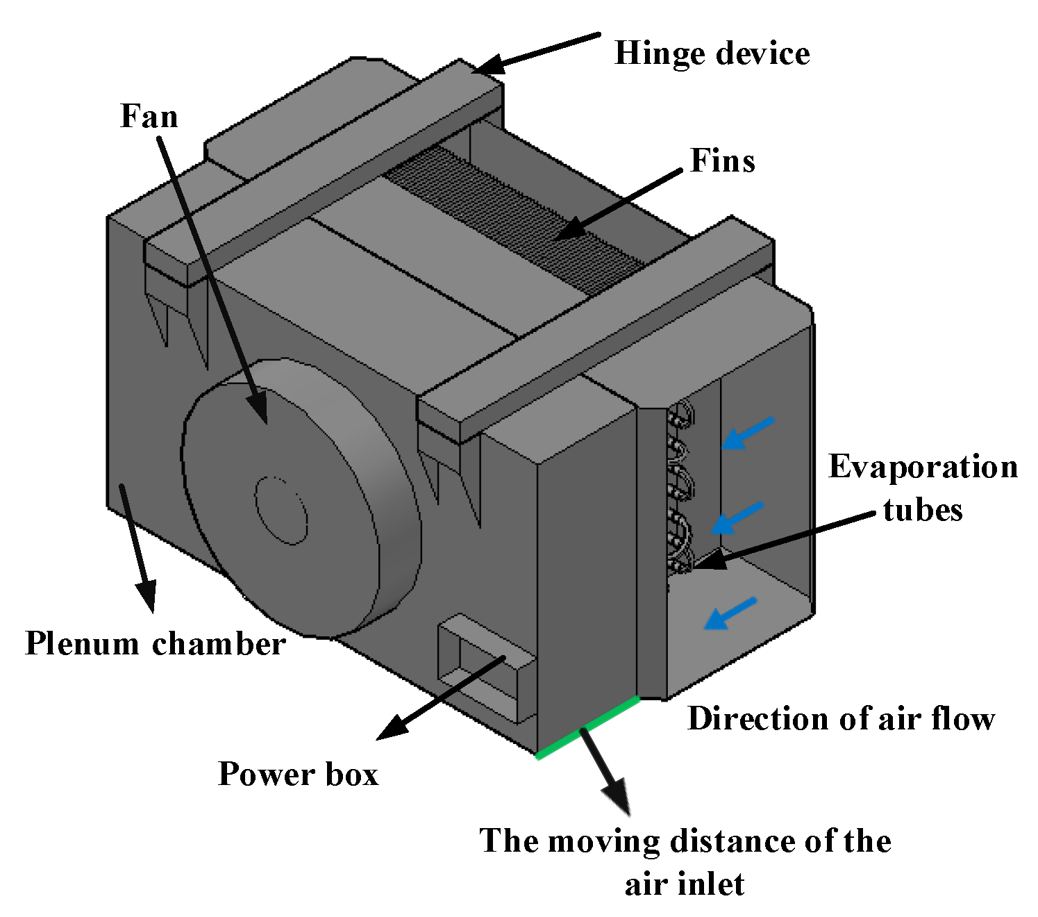
Figure 1 illustrates a schematic diagram of the experimental setup. The experimental device includes the test system, refrigeration system, monitoring system, control system, and data collection system. The test object is a customized air-cooler, which is placed in a 3840 × 2880 × 2480 (mm) cold storage with a thickness of 100 mm, a heat transfer area of 53.15 m2, a heat insulation material of polyurethane, and a thermal conductivity λ of 0.022 W/(m·K).
The refrigeration system consists of a compressor, a condenser, a reservoir, a drying filter, and an expansion valve. The refrigerant used in the experiment is R404A. The compressor is a TFH2480Z compressor from Tecumseh, France. The outer size of the condenser is 440 × 90 × 400 (mm), and the heat exchange area of the condenser is about 5.98 m2. The size of the reservoir is 280 mm in height and 130 mm in diameter, and the drying filter is EK-053. The TES02 expansion valve produced by the Denver company was used in the experiment.
The monitoring system consists of the D606 camera produced by 360 Technology Co., Ltd. (Beijing, China), which has a maximum support of 1920 × 1080 pixels, while its operating environment temperature is 269.15–313.15 K. Meanwhile, it can be monitored in real time by a computer.
The control system and data acquisition system consist of the temperature and pressure data collector, thermocouple, pressure sensor, anemometer, humidifier, hygrometer, and power meter. The MX100 serves as a real-time data acquisition-system with one end connected to a 220 V supply voltage and the other end linked to a thermocouple and a pressure sensor. The thermocouple and pressure sensor convert the temperature and pressure signals into electrical signals and then display them on the MX-100. Table 1 documents the specifications of the control devices and measuring devices used in our experiment.
Figure 2 illustrates the structure diagram of the air-cooler. The outer size of the air-cooler is 520 mm in depth, 140 mm in width, and 500 mm in height. The total area of the heat exchange on the outer surface of the air-cooler is 6.52 m2, including 56 evaporation tubes and 51 fins. The evaporation tubes are interlaced and divided into 4 rows, with each row having 14 fins. The tube spacing is 40 mm, while the fin spacing is 10 mm. The supporting fan is YSWF74L34P4-350SLF, with a rated power of 150 W, a rated speed of 1400 r/min, and an air volume of 3110 m3/h. In the experiment, the size of the air inlet surface of the air-cooler is 52 cm × 50 cm, the diameter of the fan is 350 mm, and the total thickness of the fins of the evaporation pipe is 140 mm. An important difference between our air cooler and a conventional air-cooler is the customized air outlet side, which is added with a plenum-chamber. Moreover, in our study, we define the plenum-chamber coefficient, Φ, which is the ratio of the distance between the fan and the fin over the diameter of the air outlet.
Φ = L D
The plenum-chamber is linked to the air-cooler through the hinge device on the upper side. The position of the plenum-chamber can be adjusted from the initial 260 mm up to the limit of 420 mm. Here, we selected three different values, namely 260 mm, 340 mm, and 420 mm for research. Based on these values, we can calculate the corresponding plenum-chamber coefficients, which are 0.74, 0.97, and 1.2, respectively.
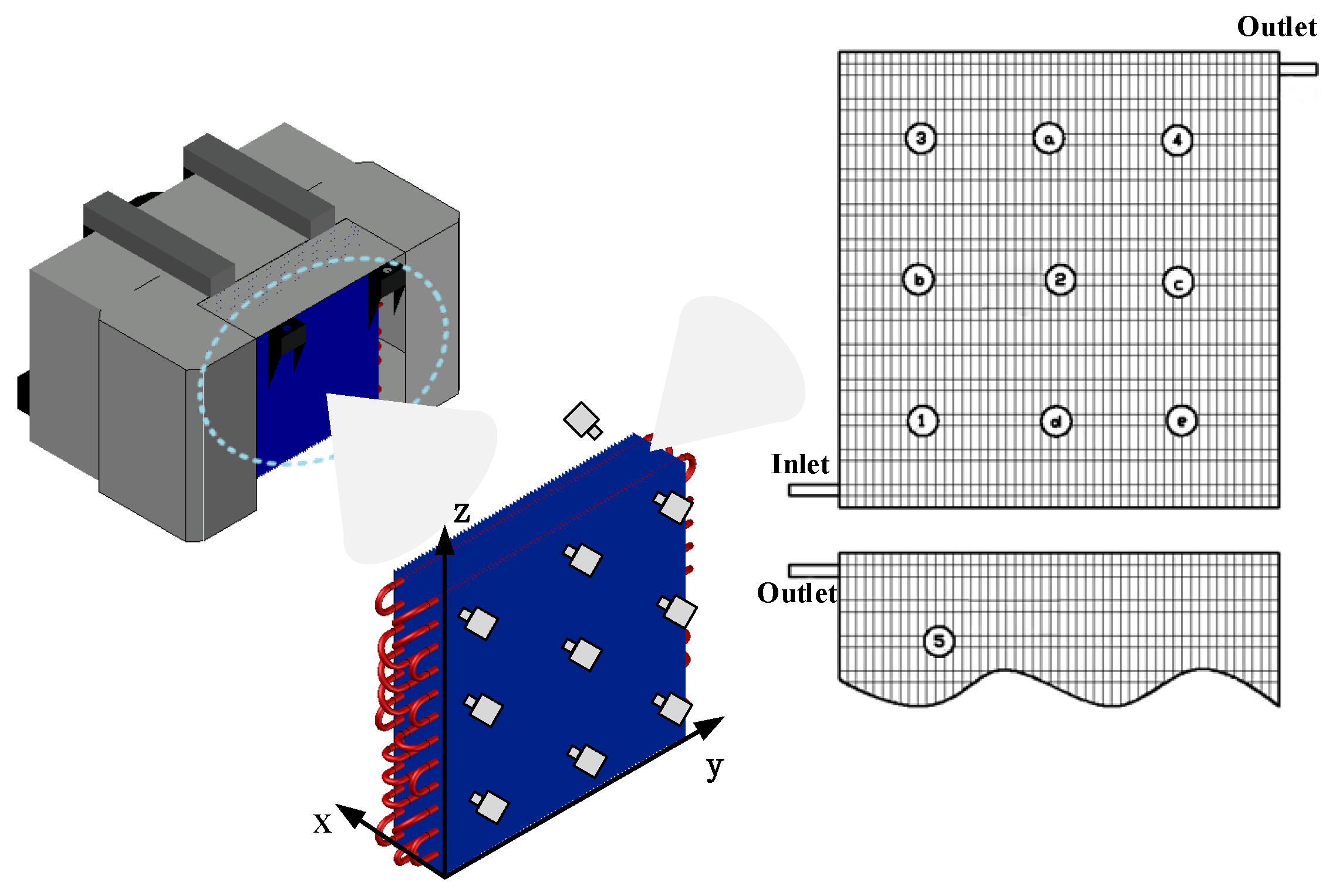
In the test part, nine positions on the inlet side and one position on the outlet side were selected as measurement points. The specific arrangement (front view) of the points is shown in Figure 3. With the lower left corner of the inlet as the reference point, we define the inlet direction as the positive one and use mm as the unit of length. Then, from left to right and from bottom to top, the coordinates of the ten measurement points are (0, 100, 100), (0, 260, 100), (0, 420, 100), (0, 100, 250), (0, 260, 250), (0, 420, 250), (0, 100, 400), (0, 260, 400) (0, 420, 400), and (140, 420, 400). Measurement points 4 and 5 are located on the inlet- and the outlet-side of the air-cooler, respectively, and have equal values on the Y and Z axes.
For the air velocity measurement, the probe is placed on nine different measurement points on the inlet side. Moreover, the air velocity is converted into an electrical signal by the air velocity probe and, in this way, is displayed on the anemometer. Five points are selected to analyze the thickness of the frost layer marked as No. 1–5. The cameras are fixed at the edge of the air-cooler at 5 mm, and the fins and evaporation tubes at five measurement points are regularly photographed. The frost thickness is obtained by comparing the thickness between the fins and the evaporation tubes after frosting at different moments.

2.2. Experimental Procedures

The experimental procedures are as follows:
(1)
According to the schematic diagram of the experiment, the compressor, air-cooled condenser, reservoir, drying filter, expansion valve, air-cooler, and other components used in the experiment are connected, and the pressure measuring point is welded at the same time.
(2)
The cold section of the system is treated with heat preservation.
(3)
A vacuum pump is used to vacuum the suction port of the compressor for 2 h, carry out the pressure holding treatment, observe the pressure change, and correct the indication of the pressure sensor on the computer end.
(4)
The measuring points are placed at the targeted temperature and humidity. We connect the data acquisition instrument, adjust the settings to the required mode, and wait for the experiment to evolve.

2.3. The Conditions of Experiment

The driving force for frost formation is the mass concentration of water vapor, which depends on the temperature of the moist air and the frost. In addition, the air flow rate influences the frost mass [23]. By keeping the initial temperature of the cold storage at about 295.15 K, we adjust the humidifier to create the relative humidity of the cold storage under two different working conditions: high humidity (relative humidity 88%) and low humidity (relative humidity 65%). For these two different cases, we compare the frosting characteristics of the air-cooler at three plenum-chamber coefficients.
In order to meet the demand of high humidity, we run the system continuously for 18 h and turn on the humidifier. The rated humidification capacity is 1.8 kg/h, which keeps the water content of the cold storage always consistent during the operation of the system. The numbers of three different experiments are 1, 2, and 3, respectively. Moreover, we meet the requirements of different experiments at low humidity by closing the humidifier and reducing the initial relative humidity. The numbers of three different experiments are 4, 5, and 6, respectively. The specific parameters are reported in Table 2.
The average moisture content can be calculated by Formula (2). The average moisture content under two different humidities were 12.10 and 10.82, respectively, and the six groups of experimental deviations were within the reasonable error range.
w a ¯ = ( w a 1 + w a 2 + w a 3 ) / 3
where w a ¯ is the average moisture content, and wa1, wa2, and wa3 are the corresponding moisture contents under each group of experiments, respectively.

3. Results

3.1. The Influence of Different Plenum-Chamber Coefficients on Air Flow Rate

Firstly, this paper explores the influence of different plenum-chamber coefficients on air velocity. The initial temperature of the experiment is set at 295.15 K, the relative humidity is adjusted, and the initial moisture content in the cold storage is within 5% of the average value to ensure the accuracy. Under this condition, the only component of the system that operates in our experiment is the fan. Table 3 documents the air flow rate at each measuring point on the inlet side under different plenum-chamber coefficients.
v ¯ = v 1 + v 2 + + v 9
S 2 = ( v i v ¯ ) 2 9
The sample variance of the wind speed is S2 Equation (4), where vi is the wind speed at different measurement points (i takes 1–9), and v ¯ is the average wind speed.
Figure 4 shows the velocity distribution cloud map of each measuring point on the inlet surface with different plenum-chamber coefficients. The S2 in each of the three experiments is 0.051, 0.034, and 0.023, which means that the uniformity of the wind velocity field increases with the increase in the plenum-chamber coefficient. At the same time, v ¯ is 3.03 m/s, 2.85 m/s, and 2.66 m/s, respectively, while its average velocity is decreasing. This is mainly due to the increase in the plenum-chamber coefficients, which reflect the increase in the distance from the fan to the fins. In turn, this results in the increase in the resistance of the air along the way and the decrease in the average speed. Meanwhile, the air speed at the center point is lower, because the air inlet is relatively close to the center, which affects the flow of the air inlet in the center area.

3.2. The Influence of Different Plenum-Chamber Coefficients on the System under High Humidity

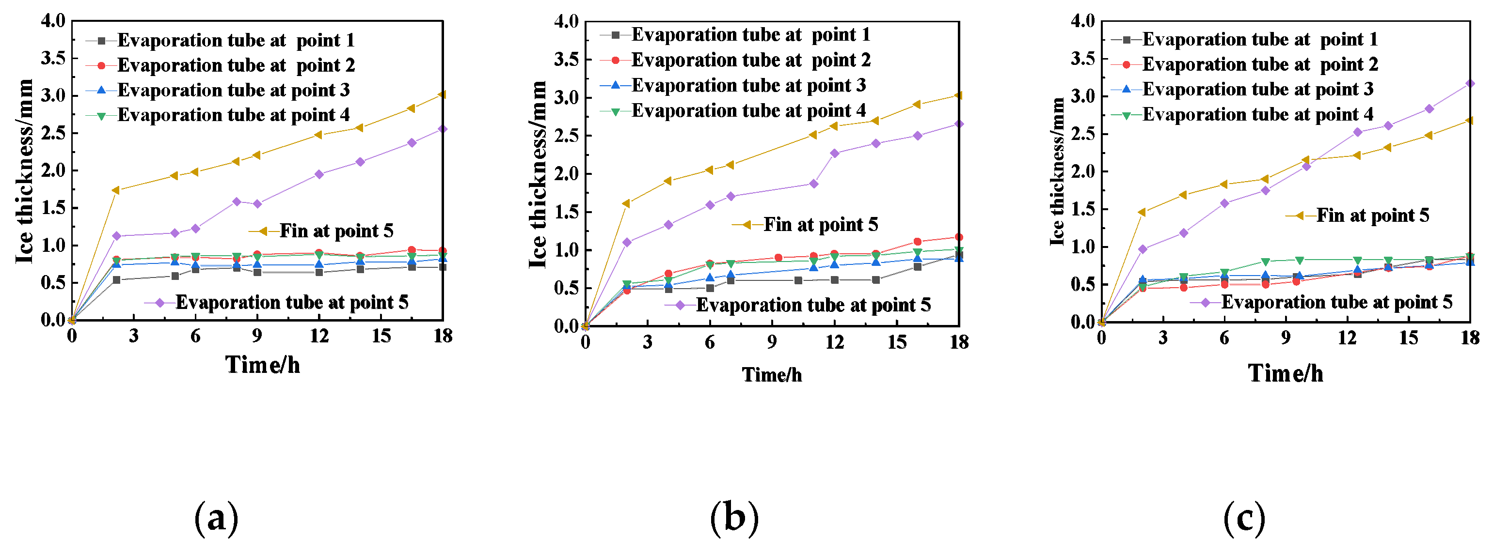
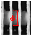
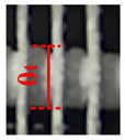
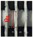
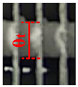
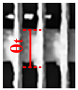
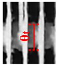
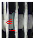
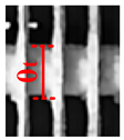
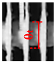
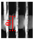
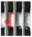
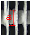
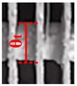
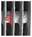
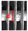
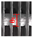
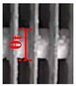
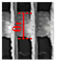
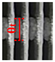
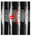
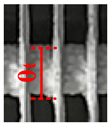
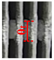
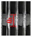
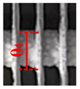
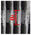
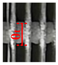
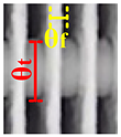
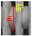
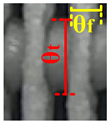
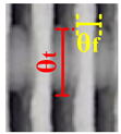
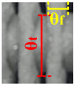
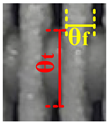
Table 4 shows the growth of frost on the evaporation tubes and the fins at five measuring points under different plenum-chamber coefficients. We observe that the thickness of the evaporation tube and the fin at the observation point changes in comparison with the initial thickness, which is the result of frost on the surfaces. Moreover, the results of Figure 5 actually indicate that the growth rate of frost on the evaporation tubes and fins in the period 0–2 h is significantly faster than that in the following moments. Moreover, the frost growth rate was more strongly dependent on the relative humidity during the initial frost growth period. Additionally, the high temperature and high relative humidity in the initial stage of the cold storage result in high moisture content in the air and rapid frosting. When the temperature in the cold storage decreases (although the relative humidity is still large), the moisture content is very limited, and the temperature difference between the wet air and the cold surface gradually decreases. Finally, when the frost thickness increases, the thermal resistance and blockage ratio also increase, which results in a significantly slower rate of frosting.
During the same period, the frost growth pattern of measuring point 5 was different from that of the first four points in terms of frost thickness. In comparison with the slow increase in frost at the first four measuring points after 2 h, the frost layer growth of evaporator tubes and fins at the measuring point 5 still showed a linear growth. On the one hand, the temperature at the outlet side is lower than that at the inlet side. On the other hand, the wet air is cooled by the evaporation pipe on the air inlet side and then by the evaporation pipe on the air outlet side. According to the enthalpy humidity diagram of air, the greater the temperature difference, the greater the amount of water vapor contained in the air. The relative humidity at the outlet side is greater than that at the inlet side. Therefore, the frosting rate at measuring point 5 is higher than that at the first four points, and the accumulated frost mass is rather due to the more active heat and mass transfer.
We also find that when the plenum-chamber coefficient is 1.2, the growth rate of the frost layer on the evaporating tube at the measurement point 5 is the fastest, but the frost thickness on the fins is the smallest, and the growth rate is the lowest. This is because, at this time, the plenum-chamber coefficient is the largest, resulting in the minimum impact of air speed. The temperature of the evaporation tube is lower than that of the fin, showing a larger temperature difference, and the evaporation tube is easier to frost than the fin. When the plenum-chamber coefficient is 0.97, the frost layer on the fin is the thickest among the cases, but the frost layer on the evaporator tube is between those with plenum-chamber coefficient 0.97 and 1.2. When the plenum-chamber coefficient is 0.74, the frost thickness on the evaporator tube is the least, but the frost thickness on the fins is between those with the plenum-chamber coefficient 0.97 and 1.2. This because a reduction in the plenum-chamber coefficient to 0.74 and 0.97 leads to a higher air speed, which causes more water vapor to be carried out to the measuring point 5. At this time, the frost layer of the fin is thicker than that of the evaporation tube.

3.3. The Influence of Different Plenum-Chamber Coefficients on the System under Low Humidity

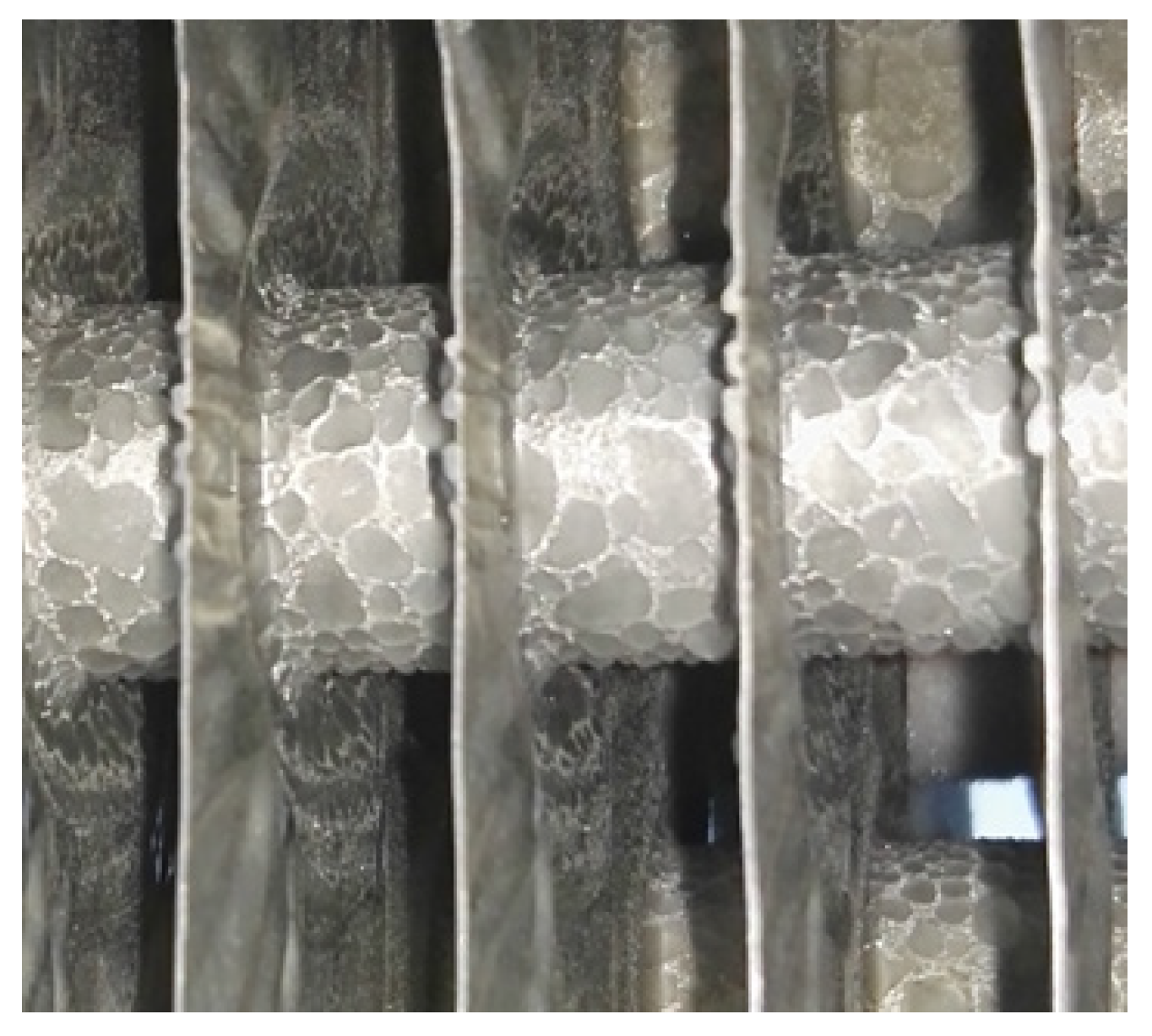
Figure 6 shows the freezing phenomenon of the evaporation pipe in the front of the air-cooler. Since there is no humidifier, even if the machine is turned on continuously for 18 h, the frost at the four measuring points on the air inlet side is limited, with only some scattered ice cubes appearing. In comparison with the first four points, the frost layer of measuring point 5 is more significant under high humidity. Therefore, for systems with low humidity, we need to pay more attention to measuring point 5 at the outlet.
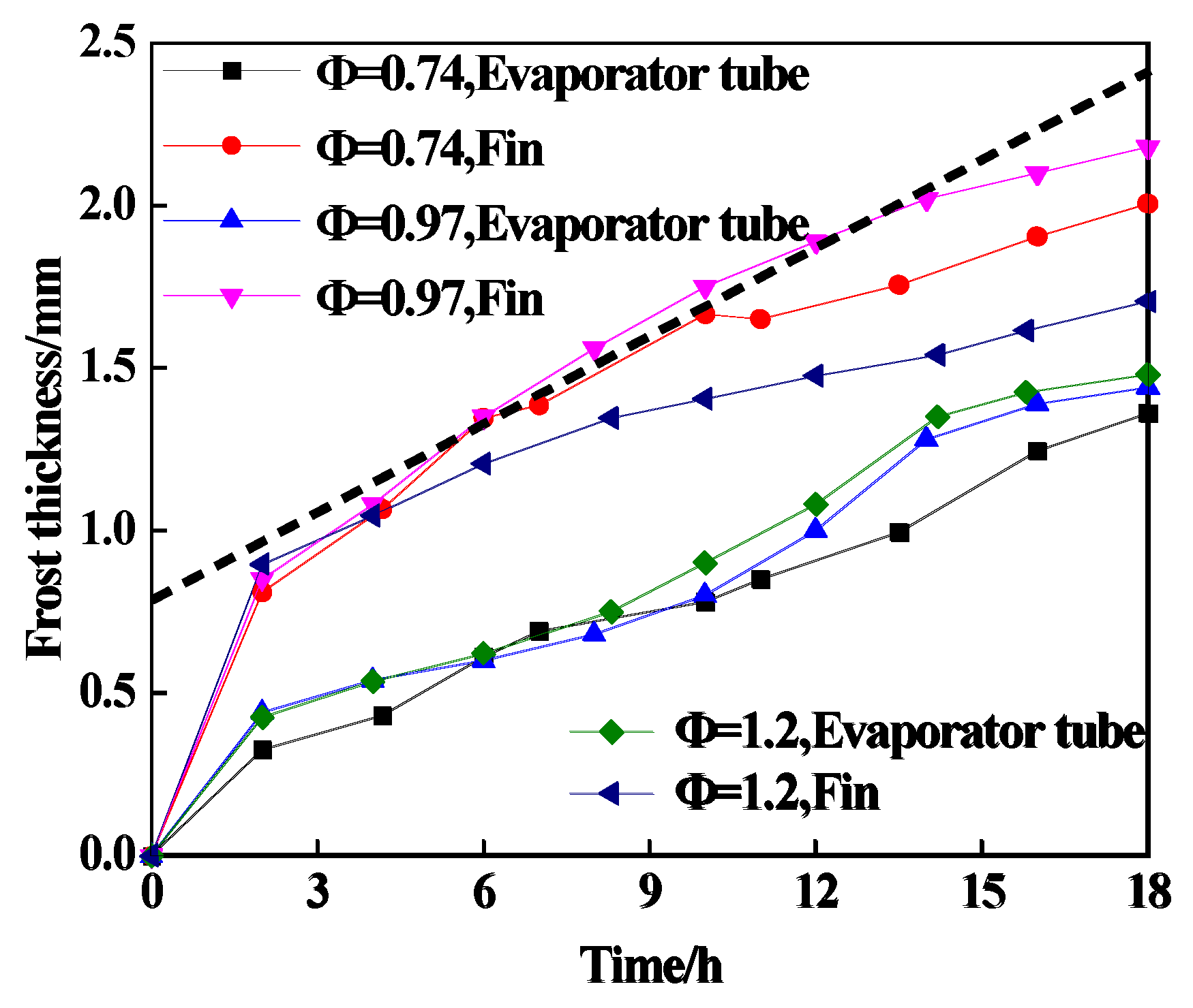
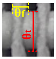
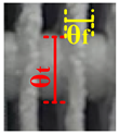
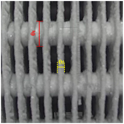
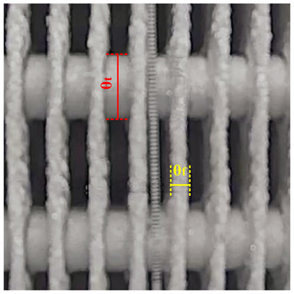
Combining Table 5 and Figure 7, we find that the amount of frost on the evaporating tube at measuring point 5 under different plenum-chamber coefficients is less than that of the fins. When Φ = 0.97, the maximum frosting thickness of the fins at the measuring point 5 is 2.18 mm, but the difference in frosting thickness is still large compared to the case of high humidity conditions, reaching 0.85 mm. The main reason is attributed to the humidification without the use of humidifier, since the humidity gradually decreases as the system continues to operate. Similarly to the high humidity conditions, the frost thickness increased rapidly in the first two hours, followed by a relatively slow growth rate in the following 16 h. Regardless of whether the humidity is high or low, when Φ = 0.97, the frost quantity becomes the most significant, because the air speed conditions at this time are most suitable for frosting.

4. Derivation of Dimensionless Analytic Fitting Curves

Due to the limitations of the experimental results, only the frosting of the evaporator tubes and fins at the measuring point 5 are analyzed, and the curve is fitted. When the air passes over the fins and the evaporation tube, the Reynolds numbers are quite different, so we discuss them separately.

4.1. Dimensionless Relation for Frosting on Air-Cooler Fins

For the fin, the frost layer within 0–2 h has its own special initial conditions. Hence, according to the experimental results, only the part of 2–18 h will be analyzed in the final verification. At present, modeling and dimensionless analysis are mostly used to study the frosting amount of a single fin of an air-cooler [24]. The empirical formula related to the amount of frost and the density and thickness of the frost layer reads:
M f r = f ( ρ f r , a v e , y f r , a v e )
The dimensionless correlation formula of the amount of frosting is determined using Equation (6):
M * = f ( T * , w a , Re L , f i n , F o L , ξ f i n * κ f i n * )
M * = M f r M L ;   T * = T a T t p T a T W ;   Re L , f i n = ( u a cos θ f i n ) L f i n v ;   ξ f i n * = ξ f i n ξ f i n , r ;   κ f i n * = κ f i n κ f i n , r
where Ta is the wet air temperature; Ttp is the triple point temperature; Tw is the cold surface temperature; ξfin is the fin thickness; ξfin,r is the reference value of the fin thickness; is the thermal conductivity; κfin,r is the reference value of the thermal conductivity; wa is the moisture content; ReL,fin is the Reynolds number; FoL is the Fourier number; ξ f i n * · κ f i n * is the product of the dimensionless fin thickness and the thermal conductivity; T* is the dimensionless temperature; M* is the dimensionless mass; ML is the mass of the full volume of the frost layer; and Mfr is the frosting quality. The product of these four terms can be viewed as a fixed value due to the same equipment and the same fin. There is a distance of about 110 mm from the passage through which the air enters the fin at the measuring point 5, while the distance between the fins is 10 mm. Therefore, the fin and the air flow direction can be considered the same, that is, cos θ f i n = 1 . As a result, Equation (5) can be simplified into the following equation:
M * = f ( T * , w a , Re L , f i n , F o L )
In Equation (8), wa is the moisture content. Its value can be obtained by looking up the table of the inlet temperature and the relative humidity. FoL is the Fourier number, representing time, which is significantly related to its own thermal conductivity and shape. For the fin of the air-cooler, the frost layer can be approximated as a cube, so the ratio of the volume to the surface area in the Fourier number can be approximated by the thickness of the frost layer θ. As time progresses, the frost layer blocks part of the air passage, which causes the air speed in the passage to change. Hence, the Reynolds number is different at different times. Because the air speed of the instrument cannot be measured from the inside, it can be only approximated using a simulation. T* is the dimensionless temperature, which can be calculated according to the definition, and the triple point temperature Ttp in the expression can be approximately regarded as 273.15 K, and the wall temperature is also obtained from the simulation. During the experiment, due to the influence of various internal and external factors, some points on the measured curve will produce large errors. In this case, we need to avoid such points with large errors when choosing points. During the frosting period of measuring point 5, the temperature in the cold storage varied from 263.15 K to 277.15 K, the cold surface temperature was from 260.65 K to 270.15 K, and the relative humidity was 60–88%, and the change was small in most of the time. According to the empirical formula, a relatively accurate curve can be obtained under the experimental conditions. The following 10 points are selected for data processing, as documented in Table 6.
Since the frost quality is related to the frost thickness and the density, the frost densities of points with different numbers in the table are different. The frost density can be calculated from the experimental air speed according to Equation (9) proposed by MARK A. Dietenberger [25]. Additionally, the thermal conductivity can be acquired according to the frost density variation range of 155.9 kg/m3–215.3 kg/m3 with reference to Equation (10), proposed by Y.-X. Tao et al. [26].
ρ f r = 340 | T w | 0.445 + 25 v a
λ f r = 1.202 × 10 3 ρ f r 0.963
In the frost layer growth process, the density will also change. Therefore, we select the average density in the table state parameters in the calculation, that is, the average density is 190.2 kg/m3, and the average thermal conductivity is 0.188 W/(m·K). In the calculation of Reynolds number ReL,fin, according to the measured position, the length Lfin is 0.13 m, the air density is 1.342 kg/m3, and the viscosity 1.67 × 10⁻⁵ Pa·s. In the calculation of the Fourier number FoL, the value of the average thermal conductivity and the average density is substituted, and the specific heat capacity C is taken as 2100 J/(kg·K).
According to these conditions, the parameter values of each variable in different working conditions are listed in Table 7.
The dimensionless equation of frost layer growth is:
M f i n * = m F o L a × ( T * ) b × Re L , f i n c × w a d
We choose the appropriate values of m, a, b, c, and d, and make the selected points as well as the points on the curve as close as possible. Then, the fitting curves of the five groups of data are as follows:
M f i n * = 1.333 × 10 10 F o L 0.3764 × ( T * ) 0.1011 × Re L , f i n 2.059 × w a 1.968
M f i n * = 1.82 × 10 7 F o L 2.345 × ( T * ) 10.1768 × Re L , f i n 6.6566 × w a 39.5362
The predictions using the present fitting curves are consistent with the experimental data, with deviations of ±5.6%.

4.2. Dimensionless Relation for Frosting on Air-Cooler Tubes

Assuming that the evaporator tube and the fin have the same moisture content, the dimensionless relation of frost layer frosting on the evaporator tube is obtained by a similar method. Frost changes the geometric structure of the air passages, causing the air speed value related to the Reynolds number to change significantly. Therefore, it is necessary to combine the inlet air speed with the thickness of the frost layer in order to calculate the average speed in front of the evaporation tube. Similarly, V/A in the Fourier number is replaced by the thickness. Then, we plug the data into the equation, with the values of each dimensionless number under different working conditions shown in Table 8.
The dimensionless equation of frost layer growth is:
M t u b e * = m F o L a × ( T * ) b × Re L , f i n c × w a d
Then, we can choose the appropriate values of m, a, b, c, and d and make the selected points and points on the curve as close to the curve as possible. Then, the fitting curves of the five groups of data are described by the following mathematical expression:
M t u b e * = 10 0.1989 F o L 1.0244 × ( T * ) 0.7378 × Re L , f i n 0.8322 × w a 1.7432
The deviations of the predictions and the measured data of the parameters falls within ±11.8%.

5. Conclusions

(1)
The uniformity of the air speed field is enhanced with the increase in the plenum-chamber coefficient, but its average velocity decreases.
(2)
After 2 h, the frost layer growth of evaporator tubes, and fins at measuring point 5 showed a linear growth.
(3)
Under the high humidity condition, the thickness of the frost layer on the evaporator tube increases with the increase in the plenum-chamber coefficients, and the frost layer thickness on the fins first increases and then decreases with the increase in the plenum-chamber coefficients.
(4)
Under the low humidity condition (Φ = 0.97), the maximum frosting thickness of the fin at the five measuring points is 2.18 mm, but the frosting thickness is still very different from that of the high humidity condition. This suggests that humidity is an important factor in frost formation
(5)
The fitting curves of the fin are, respectively:
M f i n * = 1.333 × 10 10 F o L 0.3764 × ( T * ) 0.1011 × Re L , f i n 2.059 × w a 1.968
M f i n * = 1.82 × 10 7 F o L 2.345 × ( T * ) 10.1768 × Re L , f i n 6.6566 × w a 39.5362
(6)
The fitting curve of the evaporation tube is:
M t u b e * = 10 0.1989 F o L 1.0244 × ( T * ) 0.7378 × Re L , f i n 0.8322 × w a 1.7432

Author Contributions

Conceptualization and funding acquisition, B.L.; investigation, data curation, formal analysis, writing—original draft preparation and writing—review and editing, S.S.; validation, P.E.T.; software, Y.L.; methodology, A.C.; supervision, R.B. All authors have read and agreed to the published version of the manuscript.

Funding

This research has received funding from the Tianjin Committee of Agriculture and Rural Affairs (Grant No. 201901290).

Conflicts of Interest

The authors declare no conflict of interest.

References

  1. Deng, D.; Xu, L.; Xu, S. Experimental investigation on the performance of air cooler under frosting conditions. Appl. Therm. Eng. 2003, 23, 905–912. [Google Scholar] [CrossRef]
  2. Bayrak, E.; Çağlayan, A.; Konukman, A.E.S. Experimental investigation of the effect of air velocity on a unit cooler under frosting condition: A case study. Heat Mass Transf. 2017, 53, 3119–3128. [Google Scholar] [CrossRef] [Green Version]
  3. Liu, Z.; Wang, H.; Zhang, X.; Meng, S.; Ma, C. An experimental study on minimizing frost deposition on a cold surface under natural convection conditions by use of a novel anti-frosting paint. Part I. Anti-frosting performance and comparison with the uncoated metallic surface. Int. J. Refrig. 2006, 29, 229–236. [Google Scholar] [CrossRef]
  4. Song, M.; Dang, C. Review on the measurement and calculation of frost characteristics. Int. J. Heat Mass Transf. 2018, 124, 586–614. [Google Scholar] [CrossRef]
  5. Nasr, M.R.; Fauchoux, M.; Besant, R.W.; Simonson, C.J. A review of frosting in air-to-air energy exchangers. Renew. Sustain. Energy Rev. 2014, 30, 538–554. [Google Scholar] [CrossRef]
  6. Chu, F.; Wu, X.; Wang, L. Meltwater evolution during defrosting on superhydrophobic surfaces. ACS Appl. Mater. Interfaces 2018, 10, 1415–1421. [Google Scholar] [CrossRef]
  7. Lee, Y.B.; Ro, S.T. Frost formation on a vertical plate in simultaneously developing flow. Exp. Therm. Fluid Sci. 2002, 26, 939–945. [Google Scholar] [CrossRef]
  8. Lai, T.; Ding, P.; Dong, X.; Zhang, B.; Chen, X.; Hou, Y. Experimental study on the frosting characteristics of round tube in confined circular flow path at low temperature. Appl. Therm. Eng. 2020, 171, 115075. [Google Scholar] [CrossRef]
  9. Cheng, C.; Wu, K. Observations of early-stage frost formation on a cold plate in atmospheric air flow. J. Heat Transf. 2003, 125, 95–102. [Google Scholar] [CrossRef]
  10. Ye, H.-Y.; Park, J.-S.; Lee, K.-S. Frost retardation on fin-tube heat exchangers using mass transfer characteristics with respect to air velocity. Int. J. Heat Mass Transf. 2014, 79, 689–693. [Google Scholar] [CrossRef]
  11. Yan, W.-M.; Li, H.-Y.; Wu, Y.-J.; Lin, J.-Y.; Chang, W.-R. Performance of finned tube heat exchangers operating under frosting conditions. Int. J. Heat Mass Transf. 2003, 46, 871–877. [Google Scholar] [CrossRef]
  12. Seker, D.; Karatas, H.; Egrican, N. Frost formation on fin-and-tube heat exchangers. Part II—Experimental investigation of frost formation on fin-and-tube heat exchangers. Int. J. Refrig. 2004, 27, 375–377. [Google Scholar] [CrossRef]
  13. Liu, Z.; Dong, Y.; Li, Y. An experimental study of frost formation on cryogenic surfaces under natural convection conditions. Int. J. Heat Mass Transf. 2016, 97, 569–577. [Google Scholar] [CrossRef]
  14. Wu, X.; Chu, F.; Ma, Q.; Zhu, B. Frost formation and frost meltwater drainage characteristics on aluminum surfaces with grooved structures. Appl. Therm. Eng. 2017, 118, 448–454. [Google Scholar] [CrossRef]
  15. Ren, L.; Jiao, W.; Tian, G.; Tian, X.; Liu, S. Frosting characteristics and prediction of thickness of frost layer on a finned tube in regasification process of cryogenic liquids. Int. J. Refrig. 2021, 129, 52–59. [Google Scholar] [CrossRef]
  16. Rahman, M.A.; Jacobi, A.M. Condensation, frost formation, and frost melt-water retention characteristics on microgrooved brass surfaces under natural convection. Heat Transf. Eng. 2013, 34, 1147–1155. [Google Scholar] [CrossRef]
  17. Chen, C.; Shiu, C. Frost formation and frost crystal growth on a cold plate in atmospheric air flow. Int. J. Heat Mass Transf. 2002, 45, 4289–4303. [Google Scholar] [CrossRef]
  18. Kim, D.; Kim, C.; Lee, K. Frosting model for predicting macroscopic and local frost behaviors on a cold plate. Int. J. Heat Mass Transf. 2015, 82, 135–142. [Google Scholar] [CrossRef]
  19. Wu, X.; Ma, Q.; Chu, F.; Hu, S. Phase change mass transfer model for frost growth and densification. Int. J. Heat Mass Transf. 2016, 96, 11–19. [Google Scholar] [CrossRef]
  20. Negrelli, S.; Cardoso, R.P.; Hermes, C.J.L. A finite-volume diffusion-limited aggregation model for predicting the effective thermal conductivity of frost. Int. J. Heat Mass Transf. 2016, 101, 1263–1272. [Google Scholar] [CrossRef]
  21. Brèque, F.; Nemer, M. Frosting modeling on a cold flat plate: Comparison of the different assumptions and impacts on frost growth predictions. Int. J. Refrig. 2016, 69, 340–360. [Google Scholar] [CrossRef]
  22. Benítez, T.; Sherif, S.A. Modeling spatial and temporal frost formation with distributed properties on a flat plate using the orthogonal collocation method. Int. J. Refrig. 2017, 76, 193–205. [Google Scholar] [CrossRef]
  23. Liu, X.; Yu, J.; Yan, G. An experimental study on the air side heat transfer performance of the perforated fin-tube heat exchangers under the frosting conditions. Appl. Therm. Eng. 2020, 166, 114634. [Google Scholar] [CrossRef]
  24. Ren, L.; Jiao, W.; Tian, X.; Liu, T. Effect of frost layer on heat transfer of cryogenic fluid in a finned tube. Cryogenics 2020, 109, 103115. [Google Scholar] [CrossRef]
  25. Dietenberger, M.A. Generalized correlation of the water frost thermal conductivity. Int. J. Heat Mass Transf. 1983, 26, 607–619. [Google Scholar] [CrossRef]
  26. Tao, Y.-X.; Besant, R.W.; Rezkallah, K.S. A mathematical model for predicting the densification and growth of frost on a flat plate. Int. J. Heat Mass Transf. 1993, 36, 353–363. [Google Scholar] [CrossRef]
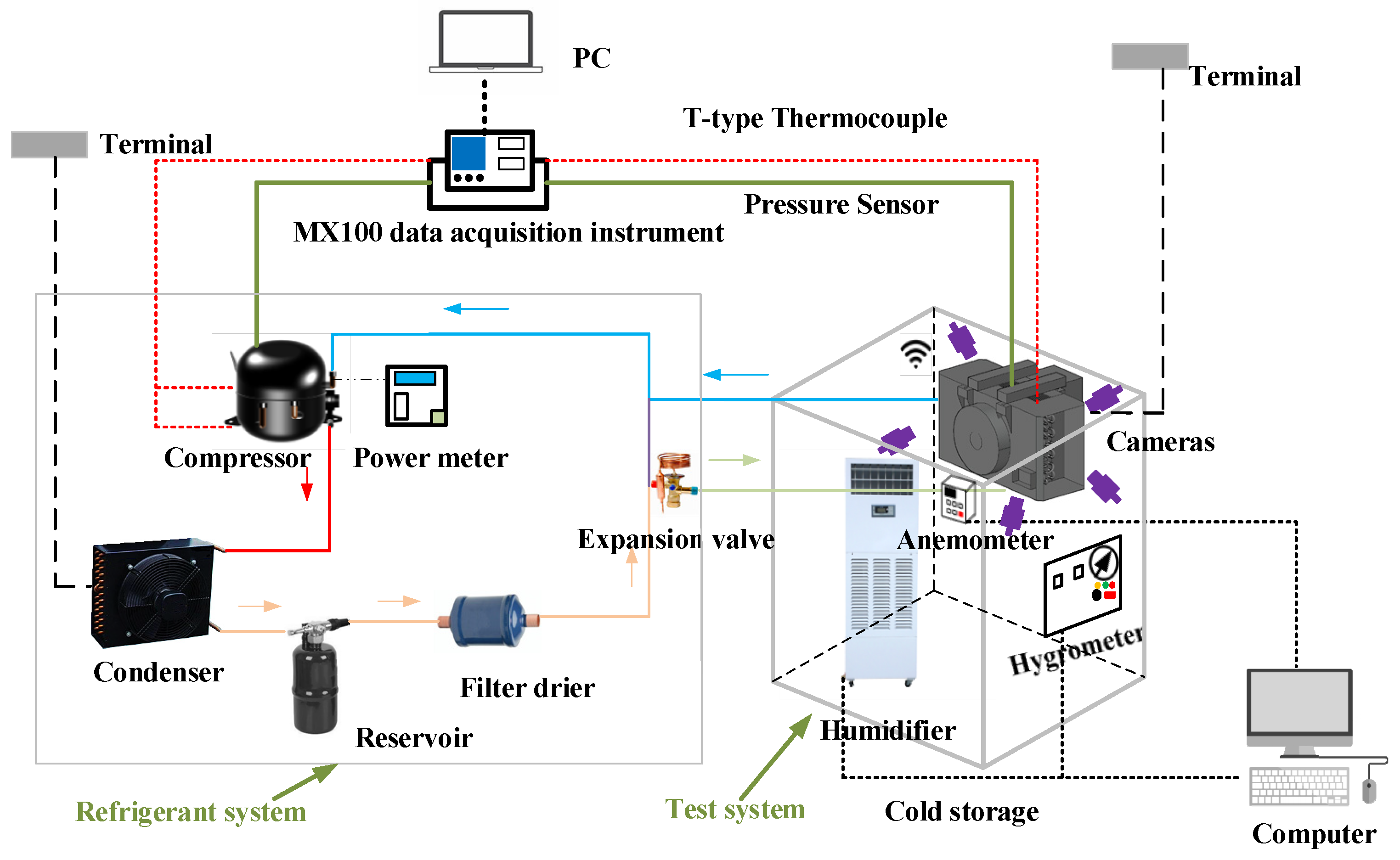
Figure 1. Schematic diagram of the experimental setup.
Energies 15 00422 g001
Figure 2. Concrete structure diagram of the air-cooler.
Energies 15 00422 g002
Figure 3. Schematic diagram of five experimental measuring points.
Energies 15 00422 g003
Figure 4. Velocity distribution of air inlet under different plenum-chamber coefficients: (a) velocity distribution of air inlet at Φ = 0.74; (b) velocity distribution of air inlet at Φ = 0.97; (c) velocity distribution of air inlet at Φ = 1.2.
Energies 15 00422 g004
Figure 5. Frost curves of points to be measured under different plenum-chamber coefficients, which are 0.74 (a), 0.97 (b), and 1.2 (c), respectively.
Energies 15 00422 g005
Figure 6. The freezing phenomenon of evaporator tube in front of the air-cooler.
Energies 15 00422 g006
Figure 7. Comparison of frost thickness at point 5 under different plenum-chamber coefficients.
Energies 15 00422 g007
Table 1. Specifications of the control and measuring devices.
ParameterDevicesTypeRangeAccuracy
Ambient/cold storage/Inlet and outlet of the compressor/Air inlet and outlet of the air-cooler temperatureThermocoupleT-type Thermocouple73.15 K to 623.15 K±0.75%
Compressor inlet and exhaust pipe pressurePressure SensorEET-1000 MPa to 12 MPa±0.5% FS
Humidity in cold storageHumidifierSJ-01268.15 K to 313.15 K-
Inlet and outlet humidity of the air-coolerHygrometerCF5020Y0 RH to 100% RH±2%
Air speed of air inlet surface of the air-coolerAnemometer6243 Multipoint Anemometer0 m/s to 9.9 m/s±0.01 m/s
Compressor powerPower meterWT310E power meter0 V to 600 V
0 A to 20 A
±0.5%
Table 2. Initial parameters in cold storage under high and low humidity.
No.Plenum-Chamber Coefficient ΦInitial Temperature of Cold Storage (K)Relative Humidity (%)Moisture Content wa (g/kg)
10.74291.658811.75
20.97292.658912.58
31.2292.158711.97
40.74294.756510.65
50.97295.856511.25
61.2294.956510.56
Table 3. Air flow rate at each measuring point of the inlet under different plenum-chamber coefficients.
Plenum-Chamber Coefficient ΦPoint 3Point aPoint 4Point bPoint 2Point cPoint 1Point dPoint e
0.743.052.933.452.852.723.143.262.863.04
0.972.92.783.152.712.582.783.122.792.85
1.22.862.562.692.722.352.562.672.752.77
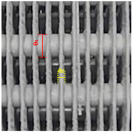
Table 4. Comparison of frost formation at 5 measuring points under different plenum-chamber coefficients, where θt is the frosting thickness of the evaporator tubes (mm) and θf is the frosting thickness of the fins (mm).
6 h12 h18 h
Φ = 0.74Φ = 0.97Φ = 1.2Φ = 0.74Φ = 0.97Φ = 1.2Φ = 0.74Φ = 0.97Φ = 1.2
1 Energies 15 00422 i001 Energies 15 00422 i002 Energies 15 00422 i003 Energies 15 00422 i004 Energies 15 00422 i005 Energies 15 00422 i006 Energies 15 00422 i007 Energies 15 00422 i008 Energies 15 00422 i009
θt = 14.06θt = 13.7θt = 13.82θt = 14θt = 13.91θt = 13.98θt = 14.12θt = 14.58θt = 14.33
2 Energies 15 00422 i010 Energies 15 00422 i011 Energies 15 00422 i012 Energies 15 00422 i013 Energies 15 00422 i014 Energies 15 00422 i015 Energies 15 00422 i016 Energies 15 00422 i017 Energies 15 00422 i018
θt = 14.38θt = 14.34θt = 13.7θt = 14.5θt = 14.6θt = 14.02θt = 14.56θt = 15.04θt = 14.46
3 Energies 15 00422 i019 Energies 15 00422 i020 Energies 15 00422 i021 Energies 15 00422 i022 Energies 15 00422 i023 Energies 15 00422 i024 Energies 15 00422 i025 Energies 15 00422 i026 Energies 15 00422 i027
θt = 14θt = 13.96θt = 13.94θt = 14.16θt = 14.3θt = 14.08θt = 14.34θt = 14.46θt = 14.28
4 Energies 15 00422 i028 Energies 15 00422 i029 Energies 15 00422 i030 Energies 15 00422 i031 Energies 15 00422 i032 Energies 15 00422 i033 Energies 15 00422 i034 Energies 15 00422 i035 Energies 15 00422 i036
θt = 14.42θt = 14.32θt = 14.04θt = 14.46θt = 14.54θt = 14.36θt = 14.44θt = 14.72θt = 14.46
5 Energies 15 00422 i037 Energies 15 00422 i038 Energies 15 00422 i039 Energies 15 00422 i040 Energies 15 00422 i041 Energies 15 00422 i042 Energies 15 00422 i043 Energies 15 00422 i044 Energies 15 00422 i045
θt = 15.15
θf = 4.9
θt = 15.88
θf = 5.31
θt = 15.86
θf = 4.9
θt = 16.6
θf = 5.89
θt = 17.24
θf = 5.46
θt = 17.75
θf = 5.67
θt = 17.81
θf = 6.97
θt = 18.01
θf = 7.27
θt = 19.04
θf = 6.6
Table 5. Pictures of frosting conditions at measuring point 5 after 18 h of system operation, where θt is the frosting thickness of the evaporator tubes (mm) and θf is the frosting thickness of the fins (mm).
Φ = 0.74Φ = 0.97Φ = 1.2
Energies 15 00422 i046 Energies 15 00422 i047 Energies 15 00422 i048
θt = 15.42
θf = 4.97
θt = 15.58
θf = 5.35
θt = 15.66
θf = 4.31
Table 6. Parameters of measured points.
No.Time τ (h)Inlet Air Speed vin (m/s)Wet Air Temperature Ta (K)Relative Humidity (%)Moisture Content wa (g/kg)Fin Temperature Tw (K)Density ρ (kg/m3)M*
122.42269.45852.43265.75200.00.35
211.51.7265.15801.66263.35165.60.50
322.34269.75852.51265.95207.30.33
422.14269.15832.33265.55196.50.30
511.51.48264.95781.59262.55161.30.45
623.25267.05791.88265.05212.40.17
711.52.56264.35781.52262.55189.40.33
822.43267.15761.83265.05202.90.18
911.52.14263.85751.39262.25176.10.28
10102.2264.55791.55262.55173.40.31
Table 7. Parameter values under different operating conditions.
No.FoLT*ReL,finMoisture Content wa (g/kg)M*
1896125,2822.430.35
232014.4417,7601.660.50
310350.8924,4462.510.33
412601.1122,3572.330.30
539503.4215,4621.590.45
640763.0533,9531.880.17
772664.8926,7441.520.33
833142.8625,3861.830.18
999155.8122,3571.390.28
1072524.1022,9831.550.31
Table 8. Parameter values under different operating conditions on evaporation tubes.
No.FoLT*ReL,finMoisture Content wa (g/kg)M*
121380.4624592.430.06
253492.3517271.660.09
322160.6223772.510.06
428550.7321742.330.05
534512.1615041.590.12
626,1181.4933021.880.02
724,3213.0326011.520.04
815,2181.6724691.830.02
918,8823.3221741.390.05
1026,8212.9722351.550.04
Publisher’s Note: MDPI stays neutral with regard to jurisdictional claims in published maps and institutional affiliations.