
Research on Homogeneous Charge Compression Ignition Combustion of Intake Port Exhaust Gas Recirculation Based on Cam Drive Hydraulic Variable Valve Actuation Mechanism


Abstract
:1. Introduction
2. Experimental Setup and Methods
2.1. Experimental Setup
2.2. Experimental Methods
3. Results and Discussions
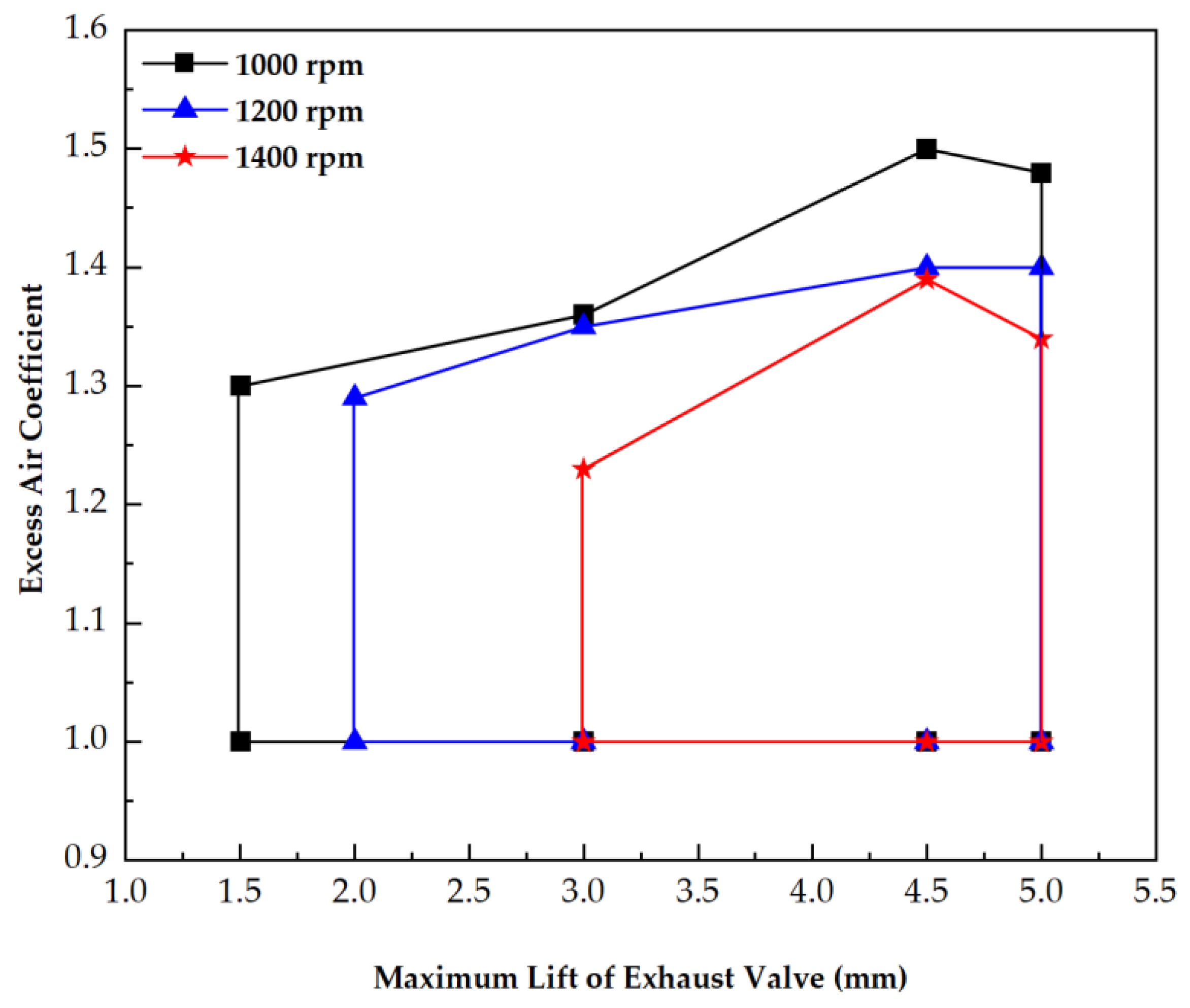
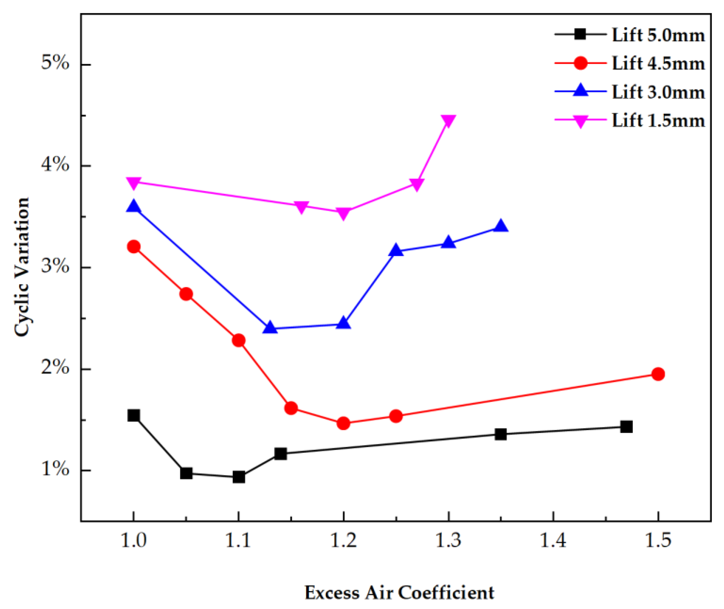
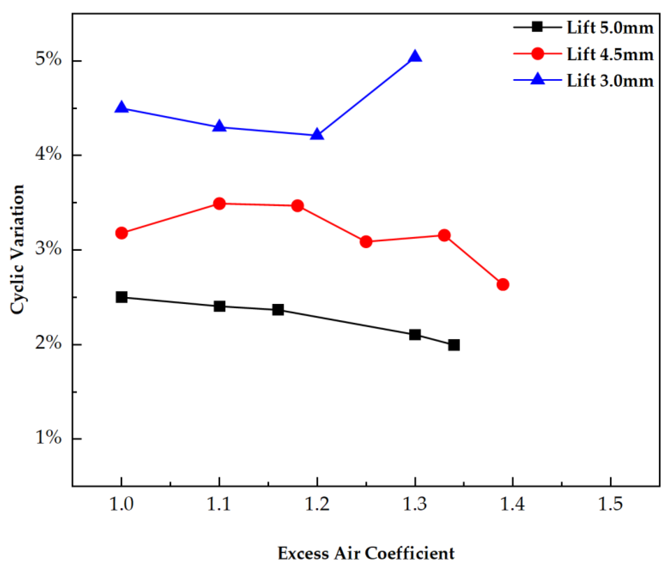
3.1. Steady State Experimental Results
3.2. Switching from SI to HCCI
4. Conclusions
Author Contributions
Funding
Acknowledgments
Conflicts of Interest
Nomenclature
| VVA | variable valve actuation |
| HCCI | homogeneous charge compression ignition |
| EGR | exhaust gas recirculation |
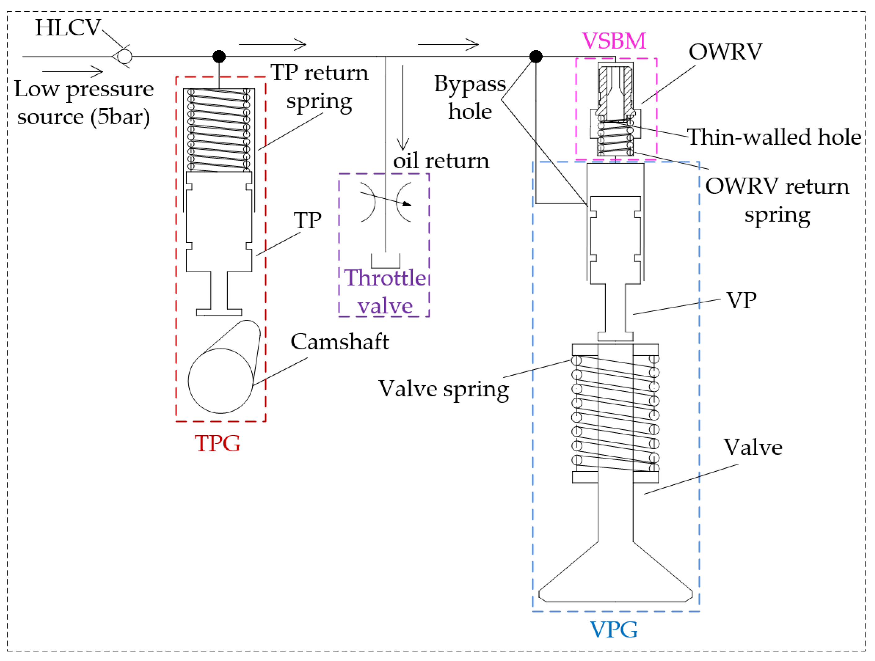
| CDH-VVA | cam driven hydraulic variable valve actuation |
| SI | spark ignition |
| CI | compression ignition |
| TPG | tappet piston group |
| VPG | valve piston group |
| HLCV | high-low check valve |
| TP | tappet piston |
| TPC | tappet piston cavity |
| OWRV | one-way restrictor valve |
| VPC | valve piston cavity |
| VSP | valve spring preload |
| VSBM | valve-seating buffer mechanism |
| ITVRA | intake throttle valve rotation angle |
| ETVRA | exhaust throttle valve rotation angle |
| λ | excess air coefficient |
| IMEP | indicated mean effective pressure |
| MLEV | maximum lift of the exhaust valve |
| CA | crank angle |
| CA10 | crank angle of 10% fuel burned |
| CA50 | crank angle of 50% fuel burned |
| CA90 | crank angle of 90% fuel burned |
| Combustion Duration | crank angle of 10%–90% fuel burned |
| BTDC | before top dead center |
References
- Joshi, A. Review of vehicle engine efficiency and emissions. SAE Int. J. Adv. Curr. Pract. Mobil. 2019, 1, 734–761. [Google Scholar]
- Lyu, M.; Bao, X.F.; Zhu, R.C.; Matthews, R. State-of-the-art outlook for light-duty vehicle emission control stand-ards and technologies in China. Clean Technol. Environ. Policy 2020, 22, 757–771. [Google Scholar] [CrossRef]
- Pan, S.; Wang, J.; Huang, Z. Development of 1.5L Dedicated Hybrid Engine with 42.6% Brake Thermal Efficiency. SAE Int. J. Engines 2021. [Google Scholar] [CrossRef]
- De Bellis, V. Performance optimization of a spark-ignition turbocharged VVA engine under knock limited oper-ation. Appl. Energy 2016, 164, 162–174. [Google Scholar] [CrossRef]
- Teodosio, L.; De Bellis, V.; Bozza, F. Combined Effects of Valve Strategies, Compression Ratio, Water Injection, and Cooled EGR on the Fuel Consumption of a Small Turbocharged VVA Spark-Ignition Engine. SAE Int. J. Engines 2018, 11, 643–656. [Google Scholar] [CrossRef]
- Onishi, S.; Jo, S.H.; Shoda, K.; Jo, P.D.; Kato, S. Active Thermo-Atmosphere Combustion (ATAC)—A New Combustion Process for Internal Combustion Engines. SAE Int. 1979, 88, 1851–1860. [Google Scholar]
- Gentili, R.; Frigo, S.; Tognotti, L.; Habert, P.; Lavy, J. Experimental Study on ATAC (Active Thermo-Atmosphere Combustion) in a Two-Stroke Gasoline Engine. SAE Int. 1997, 106, 638–644. [Google Scholar] [CrossRef]
- Noguchi, M.; Tanaka, Y.; Tanaka, T.; Takeuchi, Y. A Study on Gasoline Engine Combustion by Observation of In-termediate Reactive Products during Combustion. SAE Int. 1979, 88, 2816–2828. [Google Scholar]
- Ishibashi, Y.; Asai, M. Improving the Exhaust Emissions of Two-Stroke Engines by Applying the Activated Radical Combustion. SAE Int. 1996, 105, 982–992. [Google Scholar]
- Gowthaman, S.; Sathiyagnanam, A.P. Analysis the optimum inlet air temperature for controlling homogeneous charge compression ignition (HCCI) engine. AEJ -Alex. Eng. J. 2017, 57, 2209–2214. [Google Scholar] [CrossRef]
- Thring, R.H. Homogeneous-Charge Compression-Ignition (HCCI) Engines; SAE Technical Paper 892068; SAE: Warrendale, PA, USA, 1989. [Google Scholar] [CrossRef]
- Christensen, M.; Johansson, B.; Einewall, P. Homogeneous Charge Compression Ignition (HCCI) Using Isooctane, Ethanol and Natural Gas—A Comparison with Spark Ignition Operation. SAE Int. 1997, 106, 1104–1114. [Google Scholar] [CrossRef]
- Willand, J.; Nieberding, R.-G.; Vent, G.; Enderle, C. The Knocking Syndrome—Its Cure and Its Potential. SAE Int. 1998, 107, 1122–1129. [Google Scholar] [CrossRef]
- Kontarakis, G.; Collings, N.; Ma, T. Demonstration of HCCI Using a Single Cylinder Four-stroke SI Engine with Modified Valve Timing. SAE Int. 2000, 109, 2057–2067. [Google Scholar] [CrossRef]
- Li, J.; Zhao, H.; Ladommatos, N.; Ma, T. Research and Development of Controlled Auto-Ignition (CAI) Combustion in a 4-Stroke Multi-Cylinder Gasoline Engine. SAE Int. 2001, 110, 2114–2122. [Google Scholar] [CrossRef] [Green Version]
- Persson, H.W.; Pfeiffer, R.A.; Hultqvist, A.; Johansson, B.; Ström, H. Cylinder-to-Cylinder and Cycle-to-Cycle Variations at HCCI Operation with Trapped Residuals; SAE Technical Paper 2005-01-0130; SAE: Warrendale, PA, USA, 2005. [Google Scholar] [CrossRef]
- Takazawa, M.; Komura, K.; Kitamura, T. Transient Control Technology of Spark Assisted HCCI; SAE Technical Paper 2015-01-0880; SAE: Warrendale, PA, USA, 2015. [Google Scholar] [CrossRef]
- Cairns, A.; Blaxill, H. The Effects of Combined Internal and External Exhaust Gas Recirculation on Gasoline Controlled Auto-Ignition; SAE Technical Paper 2005-01-0133; SAE: Warrendale, PA, USA, 2005. [Google Scholar] [CrossRef]
- Zhang, Y.; Xie, H.; Zhou, N.; Chen, T.; Zhao, H. Study of SI-HCCI-SI Transition on a Port Fuel Injection Engine Equipped with 4VVAS; SAE Technical Paper 2007-01-0199; SAE: Warrendale, PA, USA, 2007. [Google Scholar] [CrossRef]
- Nier, T.; Kulzer, A.; Karrelmeyer, R. Analysis of the Combustion Mode Switch Between SI and Gasoline HCCI; SAE Technical Paper 2012-01-1105; SAE: Warrendale, PA, USA, 2012. [Google Scholar] [CrossRef]
- Liu, Y.; Li, L.; Lu, H.; Schmitt, S.; Deng, J.; Rao, L. SI/HCCI Mode Switching Optimization in a Gasoline Direct Injection Engine Employing Dual Univalve System. J. Eng. Gas Turbines Power 2019, 141, 031001.1–031001.8. [Google Scholar] [CrossRef]
- Milovanovic, N.; Dave, B.; Gedge, S.; Turner, J.W.G. Cam Profile Switching (CPS) and Phasing Strategy vs Fully Variable Valve Train (FVVT) Strategy for Transitions between Spark Ignition and Controlled Auto Ignition Modes. In Proceedings of the 2005 SAE World Congress, Detroit, MI, USA, 11–14 April 2005; 2005. [Google Scholar] [CrossRef]
- Tian, G.-H.; Wang, Z.; Ge, Q.-Q.; Wang, J.-X.; Shuai, S.-J. Study of SI-HCCI-SI mode switching in a GDI engine. Trans. CSICE 2007, 25, 229–234. [Google Scholar]
- Calam, A.; Aydoğan, B.; Halis, S. The comparison of combustion, engine performance and emission characteristics of ethanol, methanol, fusel oil, butanol, isopropanol and naphtha with n-heptane blends on HCCI engine. Fuel 2020, 266, 117071. [Google Scholar] [CrossRef]
- Verma, S.K.; Gaur, S.; Akram, T.; Samsher Kumar, A. Performance characteristic of HCCI engine for different fuels. Mater. Today: Proc. 2021, 47, 6030–6034. [Google Scholar] [CrossRef]
- Asghari, M.; Saray, R.K.; Neshat, E. Mathematical Modeling of Knocking Combustion and Created Pressure In-homogeneity Inside the Combustion Chamber in HCCI Engines Via Multi Zone Model. Flow Turbul. Combust. 2020, 105, 213–236. [Google Scholar] [CrossRef]
- D’Amato, M.; Viggiano, A.; Magi, V. On the Turbulence-Chemistry Interaction of an HCCI Combustion Engine. Energies 2020, 13, 5876. [Google Scholar] [CrossRef]
- Zhou, Y.; Lawler, B. Validation of Kinetic Mechanisms against Various Ignition Delay Data and the Development of Ignition Delay Correlations for Ethanol, Natural Gas, and Primary Reference Fuel Blends under Homogeneous Charge Compression Ignition Conditions. SAE Int. J. Engines 2021, 15. [Google Scholar] [CrossRef]
- Hikita, T.; Mizuno, S.; Fujii, T.; Yamasaki, Y.; Hayashi, T.; Kaneko, S. Study on Model-Based Control for HCCI Engine. IFAC-PapersOnLine 2018, 51, 290–296. [Google Scholar] [CrossRef]
- Nam, Y.; Kim, J.; Bahk, C.; Jang, I.; Song, H.H.; Lee, N. Modeling, Estimation, and Control of HCCI Engine with In-Cylinder Pressure Sensing. J. Dyn. Syst. Meas. Control. 2018, 140, 061015. [Google Scholar] [CrossRef]
- Zhu, D.; Deng, J.; Wang, S.; Zhang, H.; Wu, Z.; Andert, J.; Li, L. Cycle resolved control for HCCI engine load range ex-pansion by combining ion current and pressure sensor. Proc. Combust. Inst. 2021, 38, 5685–5694. [Google Scholar] [CrossRef]
- Jin, Z.; Hong, W.; You, T.; Su, Y.; Li, X.; Xie, F. Effect of Multi-Factor Coupling on the Movement Characteristics of the Hydraulic Variable Valve Actuation. Energies 2020, 13, 2870. [Google Scholar] [CrossRef]
- Wolters, P.; Salber, W.; Geiger, J.; Duesmann, M.; Dilthey, J. Controlled Auto Ignition Combustion Process with an Electromechanical Valve Train. SAE Int. 2003, 112, 160–168. [Google Scholar] [CrossRef]
- Santoso, H.; Matthews, J.; Cheng, W.K. Managing SI/HCCI Dual-Mode Engine Operation; SAE Technical Paper 2005-01-0162; SAE: Warrendale, PA, USA, 2005. [Google Scholar] [CrossRef]
- Zhao, H.; Peng, Z.; Williams, J.; Ladommatos, N. Understanding the Effects of Recycled Burnt Gases on the Con-trolled Autoignition (CAI) Combustion in Four-Stroke Gasoline Engines. SAE Int. 2001, 110, 2100–2113. [Google Scholar]
- Liu, F.-F.; Wang, Y.-K.; Li, H.; Gao, F.-J.; Huang, W.-J.; Guo, Y.-N. Performances of electro-hydraulic valve train and application. Trans. CSICE 2011, 29, 54–60. [Google Scholar]


| Engine Properties | Specifications |
|---|---|
| Engine type | Single/Horizontal |
| Combustion chamber type | ω |
| Bore/Stroke | 80 mm/80 mm |
| Connecting rod length | 130 mm |
| Displacement | 0.402 L |
| Rated speed | 2600 rpm |
| Rated power | 5.67 kW |
| Compression ratio | 17.5:1 |
| Intake valve number | 1 |
| Exhaust valve number | 1 |
Publisher’s Note: MDPI stays neutral with regard to jurisdictional claims in published maps and institutional affiliations. |
© 2022 by the authors. Licensee MDPI, Basel, Switzerland. This article is an open access article distributed under the terms and conditions of the Creative Commons Attribution (CC BY) license (https://creativecommons.org/licenses/by/4.0/).
Share and Cite
Han, L.; Duan, J.; Qian, D.; Gong, Y.; Wang, Y.; Xie, F.; Su, Y. Research on Homogeneous Charge Compression Ignition Combustion of Intake Port Exhaust Gas Recirculation Based on Cam Drive Hydraulic Variable Valve Actuation Mechanism. Energies 2022, 15, 438. https://doi.org/10.3390/en15020438
Han L, Duan J, Qian D, Gong Y, Wang Y, Xie F, Su Y. Research on Homogeneous Charge Compression Ignition Combustion of Intake Port Exhaust Gas Recirculation Based on Cam Drive Hydraulic Variable Valve Actuation Mechanism. Energies. 2022; 15(2):438. https://doi.org/10.3390/en15020438
Chicago/Turabian StyleHan, Linghai, Jiaquan Duan, Dingchao Qian, Yanfeng Gong, Yaodong Wang, Fangxi Xie, and Yan Su. 2022. "Research on Homogeneous Charge Compression Ignition Combustion of Intake Port Exhaust Gas Recirculation Based on Cam Drive Hydraulic Variable Valve Actuation Mechanism" Energies 15, no. 2: 438. https://doi.org/10.3390/en15020438
APA StyleHan, L., Duan, J., Qian, D., Gong, Y., Wang, Y., Xie, F., & Su, Y. (2022). Research on Homogeneous Charge Compression Ignition Combustion of Intake Port Exhaust Gas Recirculation Based on Cam Drive Hydraulic Variable Valve Actuation Mechanism. Energies, 15(2), 438. https://doi.org/10.3390/en15020438