Abstract
In this study, the effect of suction flow control on a centrifugal compressor at operation and stall flow rates was investigated using computational fluid dynamics (CFD). The compressor geometry was reconstructed from available open source profile data and the CFD analyses have been performed on this geometry using the appropriate mesh. To validate the CFD results, the compressor performance line was acquired and compared with the experimental results obtained at the design rotational speed. Then, suction flow control was employed at various suction slot positions with different suction flow rates to improve the performance of the compressor at operation and stall flow rates. As a result of the suction flow control trials, 0.85% increase in pressure ratio and 0.8% increase in adiabatic efficiency were achieved while the compressor was running at operation flow rate. The performance improvements corresponding to the stall flow rate of the compressor were 2.5% increase in pressure ratio and 2% increase in adiabatic efficiency.
1. Introduction
Increasing the stable operating range of the compressor is one of the designers’ goals as compressors operate at different speeds, altitudes, and temperatures. The operating range of a compressor is limited to stall and surge at low flow rates and choke at high flow rates. There are many methods developed to improve compressor operating range, and flow control is one of them. The ability to change a flow field as desired is of great importance for increasing fluid-based machinery performance. Turbulence, separation behavior, transition, and mixing can be altered with flow control methods. The method used in this study is suction flow control, which can be classified as fluidic type active flow control. In this type of flow control, the fluid with low momentum in the boundary layer is withdrawn from small slots, and the fluid with higher momentum is transferred into the boundary layer.
As investigated in the literature, air injection method has been frequently used in most of the flow control studies as fluidic actuation in centrifugal compressors. Lawless and Fleeter [1] worked on suppressing rotating stall in a low-speed centrifugal compressor with air injection jets located in the endwall of the compressor inlet. This control system succeeded in increasing the stall margin by suppressing the first spatial mode. Nelson et al. [2] were able to reduce surging mass flow by 1 percent and increase operating range by 11 percent on an axicentrifugal turboshaft engine by using air injection actuators near the diffuser throat. Stein et al. [3] numerically investigated a high-speed centrifugal compressor numerically. After the surge phenomena were modelled, air injection trials were carried out from a slot before the leading edge of the impeller. They have been successful in reducing the surge amplitude with the trial of different injection flow rates and injection angles. Spakovszky [4] introduced a new, low-order analytical model for centrifugal compressors and reported backward rotating stall waves for the first time, based on the model air injection actuators placed between impeller and diffuser vanes of NASA CC3 high-speed centrifugal compressor. Using different numbers of injection holes and injection flow rates in the experiments, the surge margin was increased by 25%. To improve the surge margin of the NASA CC3 compressor, Skoch [5,6] tested the effects of air injection angle, injection flow rate, number of injection holes, injection spacing, and injection vs. bleed from the hub and shroud surfaces. As a result of the study, while the surge margin was improved with control methods, a decrease in the total pressure ratio of the compressor has been observed. For the best control method, the surge margin showed an improvement of 9% points. Nie et al. [7] designed a micro-air injector and tested it for axial and centrifugal compressors. Centrifugal compressor experiments were carried out at four different injection locations and two different injection flow rates. In the best result they got, they reduced the minimum flow rate at which the compressor could operate by 10%. Hirano et al. [8,9] carried out experiments to find the optimum circumferential location of air injection from the impeller inlet to extend the operating range of a centrifugal compressor. They found that the optimal position was on the opposite side of the volute tongue. In their proceeding study, the effect of a second injection was examined by fixing the optimum injector point found in the first study. With the addition of the second injection, the operating range has been increased. Taghavi-Zenouz et al. [10] numerically tested different impeller tip injection parameters on a centrifugal compressor, resulting in an optimum configuration that increased the compressor stall margin by 15%. Halawa et al. [11] numerically performed air injection studies at various injection flow rates and injection angles on the NASA CC3 compressor where actuators were placed on the shroud surface between the propeller and the diffuser. As a result of the study, the surge flow rate was decreased from 4 kg/s to 3.8 kg/s for the optimum control configuration. Gao et al. [12] carried out experimental and numerical flow control investigations on a centrifugal compressor. Similar to the previous ones, the air injection actuator was located between the impeller and the diffuser, on the shroud surface. As a result of the study, the surge margin showed an improvement of 9% points. In addition, with the effect of the injection, a decrease was observed in the efficiency and pressure ratio. Marsan et al. [13] carried out one of the most detailed numerical suction control study in the literature. In their studies, suction actuators were defined on the hub surface of the diffuser blade and the simulations were conducted by defining 1% of the surge flow rate as suction from 3 actuators. As a result, the pressure ratio improved by 1%, and the minimum stable operating flow rate was reduced by 3%. This study demonstrated the advantage of the suction flow control method by showing both surge margin and pressure ratio improvements. Mirzaee et al. [14] studied air injection method on a centrifugal compressor to increase stability. They examined different injection parameters ahead of the leading edge of the impeller and reported that this method was able to reduce the leakage flow from the propeller. Yin et al. [15] tested the effect of atomized water injection system on a centrifugal vapor compressor and showed that the stability of the compressor was increased. They pointed out that excessive water injection can cause surge state.
The aim of the current study is to improve the performance of a centrifugal compressor running at operation and stall flow rates employing the suction flow control method. As the literature review reveals, the application of suction flow control to centrifugal compressors is limited. With the work to be done, it is aimed to increase the effectiveness of this method in centrifugal compressors. In this study, the effect of positioning the suction actuators on the diffuser blade as well as the usefulness of the suction flow control method at an operating flow rate, are examined in detail.
2. Problem Definition
In order to examine the effect of suction flow control, CFD simulations with and without flow control were conducted. First, the model was run without flow control, and the flow events occurring in the compressor at different flow rates were examined. According to these investigations, potential actuator locations of the suction flow control in the compressor were identified and flow control studies were carried out.
Compressor Geometry
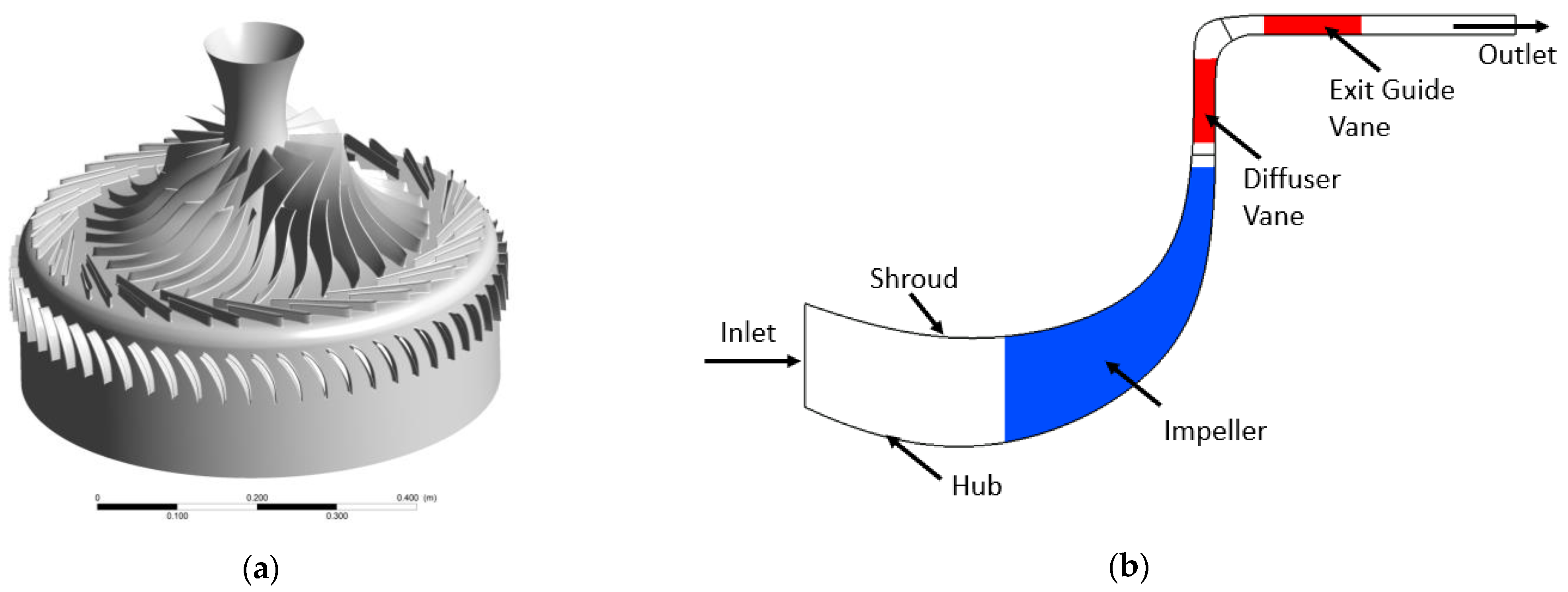
The geometry used for this study is the open-source high efficiency centrifugal compressor (HECC) which is designed and manufactured by United Technologies Research Center (UTRC) and National Aeronautics and Space Administration (NASA) [16]. The CAD geometry of the HECC is reconstructed from given profile points from the report. It comprises three rows of blades, the impeller, the diffuser, and the exit guide vanes. The HECC impeller row and the diffuser row consist of 15 and 20 pairs of blades, respectively and the EGV row has 60 cascade-type blades. The impeller has 0.3 mm clearance to the shroud, and it is included in the CFD model. The blades are connected to the hub and shroud surfaces with a radius of 2 mm, which is also included in the CFD model. The leading and trailing edges of all blades are elliptical. 3D geometry, meridional flow path, and component’s locations are shown in Figure 1.

Figure 1.
HECC geometry: (a) 3D view (Blade passages are duplicated for better figure quality); (b) Meridional section and component of the HECC.
3. Methodology
3.1. CFD Model
The three-dimensional CFD simulations were performed using Ansys CFX (version 2020 R1). ANSYS CFX solves the Reynolds-Averaged-Navier-Stokes (RANS) equations with an implicit element-based finite volume formulation [17]. The transient flow solver was chosen to account for the transient behavior of the flow and the simulations continued until the time required for the propeller to rotate 10 revolutions after the output signal became periodic. As a result, the average value of the last 10 revolutions time was evaluated. Second order accurate discretization scheme was preferred in all simulations. Since the flow was compressible, the ideal gas approach was used for the working fluid which is air. The flow was simulated as fully turbulent, and the k-ω Shear Stress Transport (SST) [18] turbulence model was employed. In many studies in the literature [19,20,21,22,23,24,25,26], k-ω SST turbulence model has been used as it can accurately model the separated flow occurring in centrifugal compressors with low computational cost. The total energy model was activated to solve heat transfer in the compressor. The readers may refer to [17,18] to be informed about the details of the governing equations and the turbulence model.
In the simulations, for the blade rows of the impeller and the diffuser, only one main blade and one splitter blade were considered to significantly reduce the computational efforts. Similarly, only one blade from the stationary EGV blade row was used. Thus, CFD simulations were carried out with a single passage of each blade row. Multiple frames of reference approach was used in the simulations in which the impeller row was modelled with rotating frame of reference, and the diffuser and EGV rows were modelled with stationary frame of reference. The performance indicators of the CFD results were chosen as pressure ratio (π) and adiabatic efficiency (η). The pressure ratio was calculated as the ratio of the total pressures taken from the inlet and outlet surfaces. The adiabatic efficiency was calculated as the ratio of the required isentropic work to the actual required work for compression process.
3.2. Boundary and Operating Conditions
In the CFD calculations, hydrodynamic and thermal boundary conditions are as follows: As the design rotational speed, 21,789 rpm was defined in the impeller region. A total pressure of 1 atmosphere and a total temperature of 15 °C were defined at the compressor inlet. Mass flow boundary condition was used at the outlet, that has been changed to simulate different operation points of the compressor. Since all blade rows contain different number of blades, the pitch ratios between domains are different, so a circumferential averaging type of interface was used between domains. The periodic boundary condition was employed for the lateral surfaces of each domain. All walls of the compressor were considered adiabatic and satisfied no slip boundary condition.
3.3. Grid Independence Tests
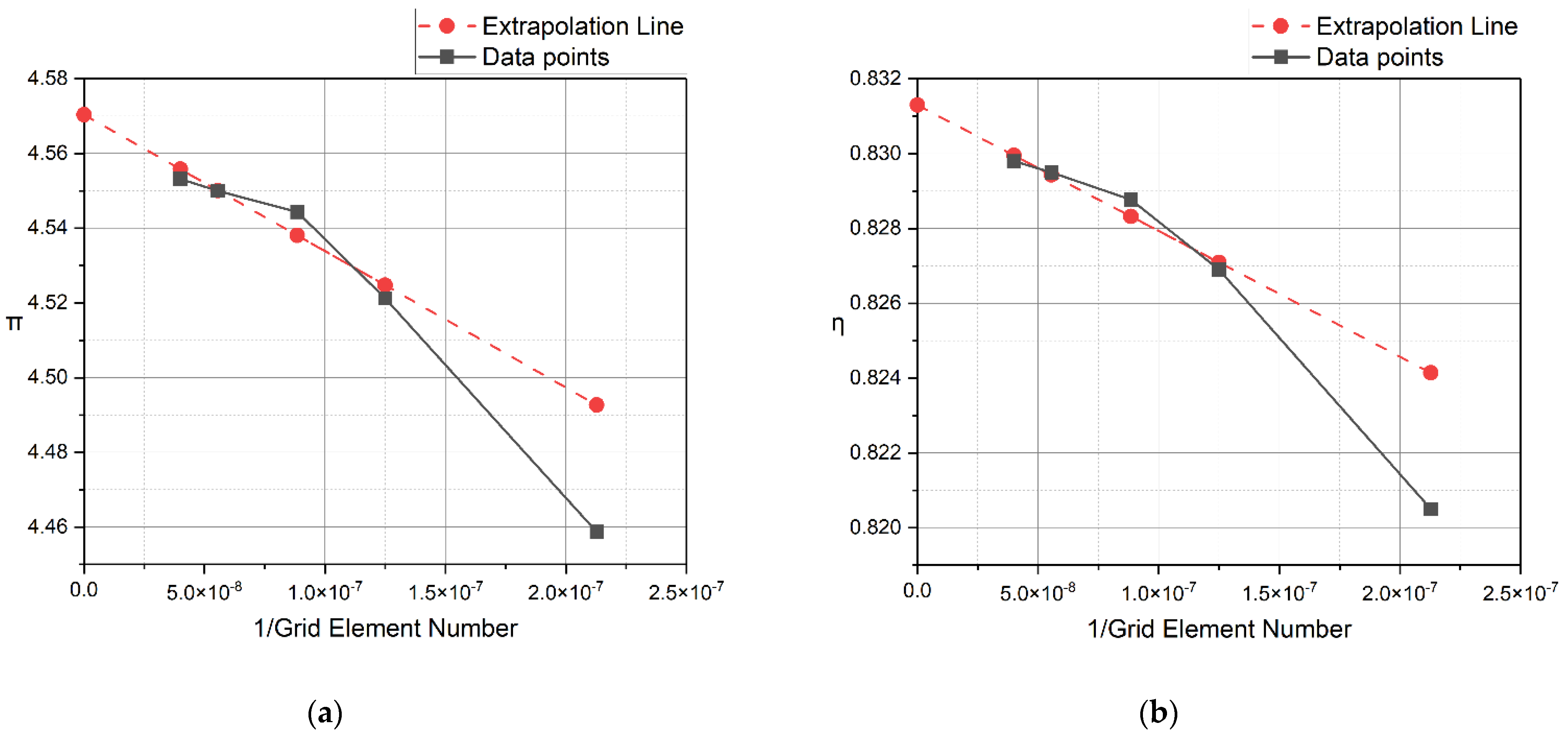
For grid generation, block structured grids with hexahedral elements were used in all regions. The grid independence tests were performed at the design rotational speed of 21,789 rpm and operation flow rate of 5.11 kg/s for five different grids and they are tabulated in Table 1. Relative errors were calculated based on the experimental data in [16]. With the solutions made, the infinite element grid was extracted as a result of extrapolation. Figure 2 shows the compressor output parameters for different grids and the extrapolated line. It was decided to use the 11.3 million element grid for further compressor operation points and suction flow control studies as it can adequately resolve the flow field with a manageable number of cells. The maximum wall y+ value for the selected grid was found below 2 with the minimum orthogonal angle of 21°. Details of the grid topology can be seen in Figure 3.

Table 1.
Grid independence tests.
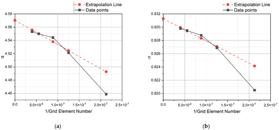
Figure 2.
Grid independence and extrapolation results: (a) pressure ratio, π; (b) adiabatic efficiency, η.
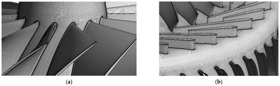
Figure 3.
A view of the grid topology (Blade passages are duplicated for better figure quality): (a) impeller leading edge; (b) diffuser vanes, EGV vanes and 90-degree turn.
The time step calculation was made according to the degree of rotation of the propeller in one time step. To achieve time step independence, simulations were completed for time step values such that the impeller rotates 2, 4, and 8 degrees in one time step. Since simulations with time step values corresponding to 2 and 4 degrees per time step were similar, time step value was selected to be 4 degrees rotation per time step.
4. Results
4.1. Compressor Operating Line: Uncontrolled Case
For the validation of the current CFD results, experimental data from [16] were utilized. Experimental studies have been carried out from choke flow rate to near-stall flow rate in the NASA Small Engine Component Test Facility at NASA Glenn Research Center by UTRC and NASA. The test rig had an uncertainty of ±17 rpm for compressor speed. Uncertainty of the flow measurement system was estimated to be ±0.05 kg/s. The pressure measurement system showed an uncertainty of ±75 Pascal for the inlet and ±400 Pascal for the outlet [16]. The CFD results were produced for different operating points and compared with the experimental data at the design speed of the impeller. Pressure ratios and adiabatic efficiencies were plotted versus the compressor mass flow rates (ṁ) and are shown in Figure 4. For the operation and stall regions, the CFD results agreed well with the experimental data. Since the suction control study focuses on the stall and operation regions, the choke region has not been extensively investigated. In CFD studies, a point lower than the minimum flow rate at which the experimental studies were completed, was also simulated. It was observed that this point was not stable due to the stall effects.
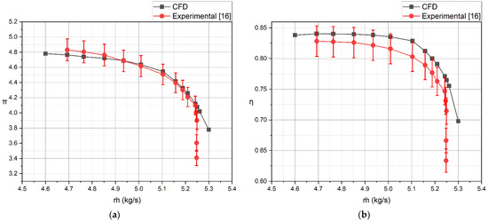
Figure 4.
Comparison of CFD and experimental results (CFD results are within an error band of ±3%): (a) pressure ratio, π; (b) adiabatic efficiency, η.
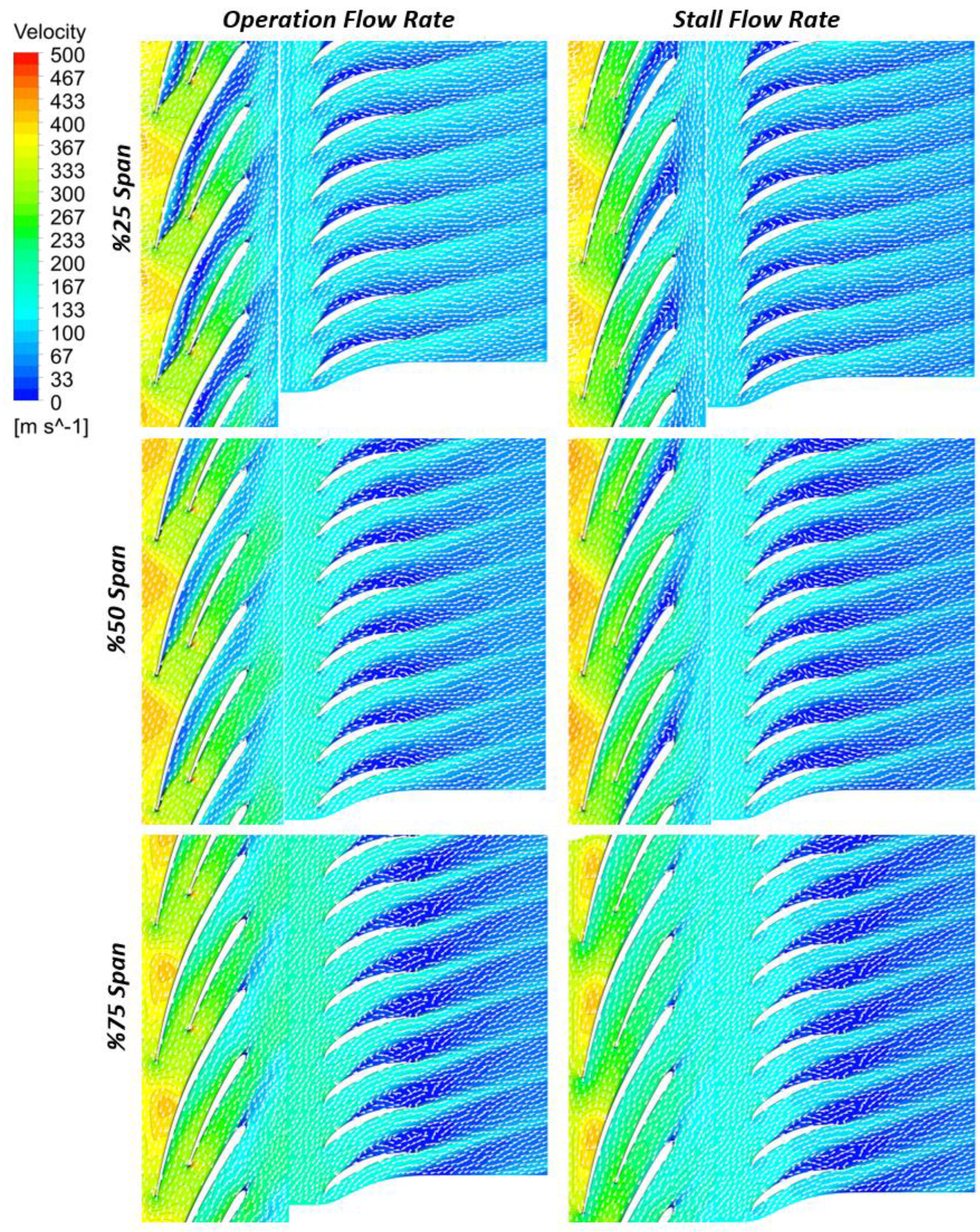
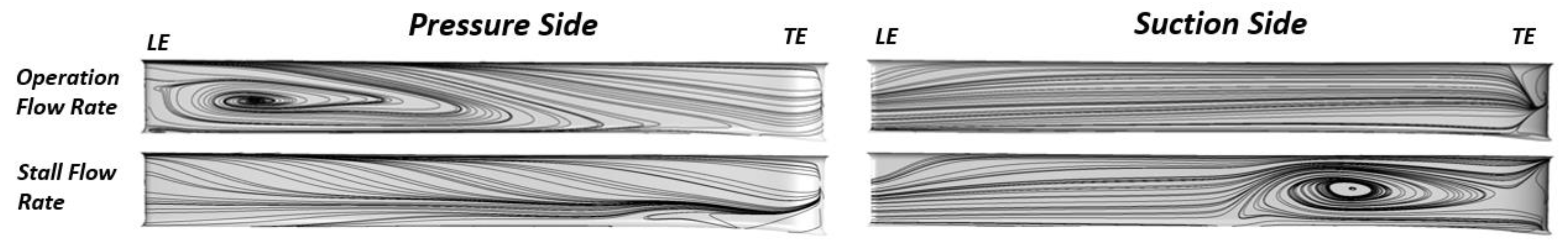
Figure 5 shows the velocity contours and vectors in the diffuser and EGV regions. While the compressor was running at the operation flow rate, a visible flow separation zone formed around the leading edge of the main diffuser blade on the pressure side closer to the hub. On the other hand, as the mass flow rates in the compressor decreased, the flow separation zone formed on the suction side of the diffuser vane near the trailing edge. This phenomenon can be seen in Figure 6, which shows streamlines near the diffuser blades. For the EGV vanes, the flow separation showed the same behavior for the operation and stall flow rates as it formed at the suction surface of the blades.
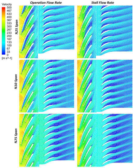
Figure 5.
Flow fields in diffuser and EGV domains for different mass flow rates and spans.
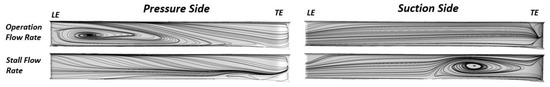
Figure 6.
Surface streamlines indicating flow separation zones on diffuser vane surfaces.
4.2. Suction Control Studies: Controlled Cases
Since the flow separation locations of the two operating points were different, the flow control study was conducted in two parts. In Table 2, the locations of the actuators for suction control actuators are indicated. For the operation mass flow rate, 8 suction control actuators were placed on the pressure side of the diffuser blade, and for the stall mass flow, 3 suction control actuators were used on the suction side of the diffuser blade. All actuators have been defined as circular holes with a diameter of 2 mm. Mass flow boundary condition was applied to each actuator and a parametric optimization was employed to determine the optimal mass flow rates for each actuator. As a strategy, the mass flow rate at the outlet of the compressor was kept constant; for instance, in case of suction by 1% of the working flow, 101% of the flow rate was defined at the compressor inlet. Thus, the components upstream of the suction actuators operated at a slightly higher load.
Table 2.
Suction actuator locations.
4.2.1. Flow Control Studies at Operation Flow Rate (O.F.R.)
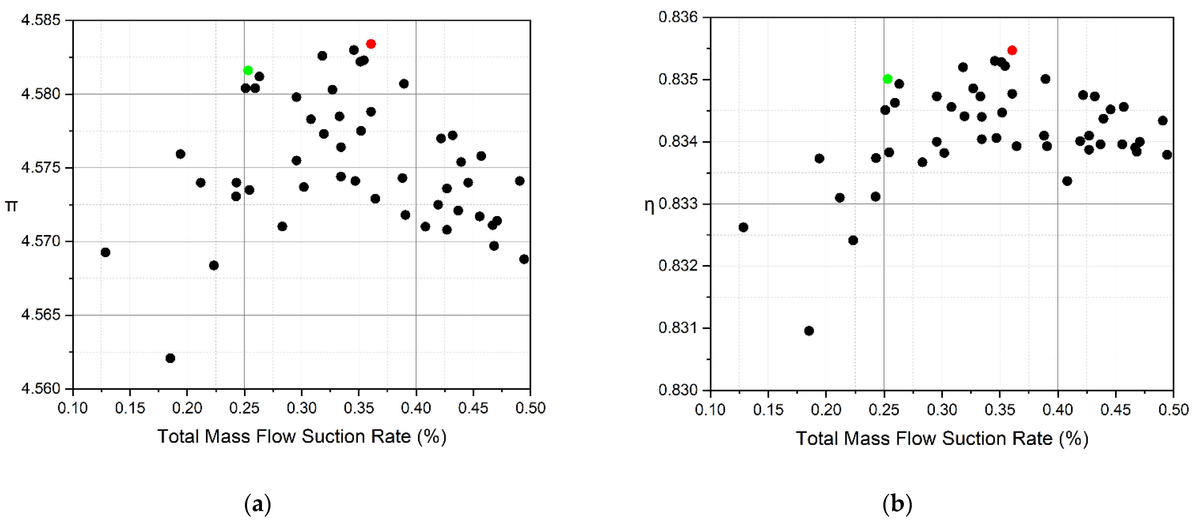
A parametric simulation was conducted to determine the suction parameters, thus a design of experiments (DOE) with 50 simulations was prepared with 8 input parameters. Input parameters were defined as mass flow rates of each different suction actuator and the target functions were determined as the pressure ratio and adiabatic efficiency. Two constraints were imposed when creating the DOE: first, a maximum of 0.2% of the main flow was allowed to exit through an actuator row, and second, a maximum of 0.5% of the main flow was allowed to exit from the sum of all actuators. Figure 7 demonstrates the distributions of these results from 50 simulations. Performance criteria is shown against total mass flow suction rate made from the actuators. The best result obtained from these analyses will be named “O.F.R. Flow Control 1”. A response surface was created from the solutions and the effects of input parameters on target functions have been examined. In the response surface, two actuators at the 2% chord location had the greatest influence on the target functions. Based on this information, a new simulation was carried out, in which only the actuators in 2% chord location were employed. Actuators operating in this simulation had the same values as O.F.R. Control 1. This new analysis was named “O.F.R. Flow Control 2”. The analysis results of O.F.R. Flow Control 1 and O.F.R. Flow Control 2 are tabulated in Table 3. As can be seen from the results, the suction flow control positively affected the performance of the compressor working at an operation flow rate. When all actuators were operating, 0.85% increase in pressure ratio and 0.8% increase in adiabatic efficiency could be achieved. If flow control was desired with fewer actuators, results close to the optimum control state could be achieved only with actuators located at 2% chord location.
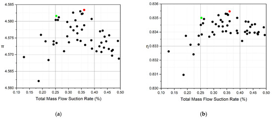
Figure 7.
Results of the DOE study, (Black: Sample Points, Red: O.F.R. Flow Control 1, Green: O.F.R. Flow Control 2): (a) pressure ratio, π; (b) adiabatic efficiency, η.
Table 3.
Numeric results of the suction flow control study for operation flow rate.
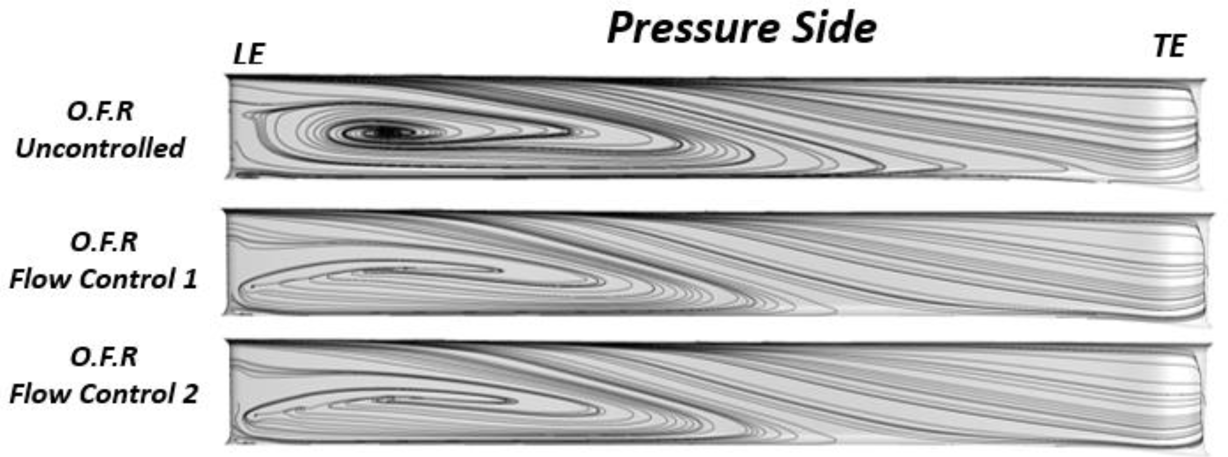
Figure 8 shows the effect of suction actuators with surface streamlines on diffuser blades. As can be seen in this figure, although the suction flow control did not completely eliminate the separation bubble on the blade, it provided a positive effect on the compressor performance by reducing its size.

Figure 8.
Surface streamline comparison of different suction control studies at operation flow rate.
4.2.2. Flow Control Studies at Stall Flow Rate (S.F.R.)
Suction flow control studies at stall mass flow rate have been performed with three suction actuators located on the suction side of the diffuser blade at 50% chord location. The mass flow rate drawn from the main flow was defined evenly through the actuators. In order to find the optimum operating performance at the stall flow rate, six different suction rates ranging from 0.1% to 1% were applied. At a suction flow rate of 0.3%, the output parameters reached their optimum state. Different compressor operating points were also tested with the optimum flow control case. As Figure 9 shows, flow control was found to be advantageous at other operating points compared to the uncontrolled case. At a flow rate of 4.6 kg/s, the suction flow control improved the pressure ratio by 2.5% and the adiabatic efficiency by 2%. With this flow control strategy, the stall margin of the compressor has been increased from 24% to 32%. Stall margin retains the physical significance of the outlet flow but measured inlet flow is also involved in the calculation; its definition can be found in [27].
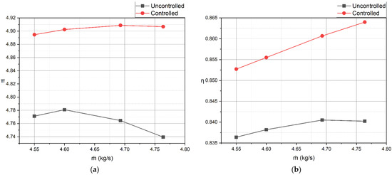
Figure 9.
Results for controlled and uncontrolled cases near stall flow rate: (a) pressure ratio, π; (b) adiabatic efficiency, η.
Figure 10 shows the streamlines formed on the diffuser blade with and without suction control. It can be seen that the resulting flow separation bubble on the suction surface, which is thought to have an effect on performance increase, has been eliminated.
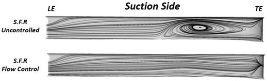
Figure 10.
Surface streamline comparison of controlled and uncontrolled diffuser blade for stall mass flow.
Figure 11 demonstrates the pressure ratio signals for uncontrolled and controlled cases that work at stall flow rate. There was a 40-fold difference in the amplitude of the pressure ratio fluctuation between uncontrolled and controlled cases.
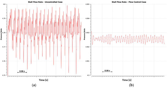
Figure 11.
Pressure ratio signals from uncontrolled and controlled cases working at stall flow rate: (a) uncontrolled case; (b) controlled case.
5. Discussion
In this study, the operating line of the HECC was obtained with the CFD simulations. Upon examination of the flow structures on the diffuser blade, the locations of the actuators to be used in suction flow control at the stall and operation flow rates were found.
The curative effects of the suction flow control method on centrifugal compressors have been shown for both operation and stall flow rates. In literature, the suction flow control method has been shown to be effective for surge flow, in the current study however, it has been revealed that the suction flow control can affect the compressor performance in a wider area at the operation flow rates.
It has been observed that if suction flow control actuators are positioned on blade surfaces instead of hub or shroud surfaces, it will be more effective. It will perform best if the suction actuators are placed just before the flow separation.
Suction flow control helped reattach the flow at standard operation flow rates, resulting in increased compressor performance. But at stall flow rates, the benefit of suction flow control was more significant than at operation flow rates. Performance and operating range of the compressor have been improved by eliminating the separated flow on the suction side of the diffuser blade with a lower suction flow rate.
6. Conclusions
Suction flow control increased the pressure ratio by 0.85% and the adiabatic efficiency by 0.8% compared to the uncontrolled case at the operation flow rates. Compared to the stall flow rate, suction flow control increased the pressure ratio by 2.5% and the adiabatic efficiency by 2%. With the involvement of flow control, the stall margin in the compressor has been increased from 24% to 32%. According to these results, the suction flow control method is a conceivable and promising active flow control strategy to increase the stable operation range and improve the performance of the centrifugal compressors. Future studies will explore the effects of different types of fluid-based actuators including pulsed suction flow control and zero net mass flux type actuators.
Author Contributions
Conceptualization, S.E.A. and S.C.; methodology, S.E.A.; software, S.E.A.; validation, S.E.A.; formal analysis, S.E.A.; investigation, S.E.A.; resources, S.E.A. and S.C.; data curation, S.E.A.; writing—original draft preparation, S.E.A.; writing—review and editing, S.C.; visualization, S.E.A.; supervision, S.C.; project administration, S.C. All authors have read and agreed to the published version of the manuscript.
Funding
This research received no external funding.
Institutional Review Board Statement
Not applicable.
Informed Consent Statement
Not applicable.
Data Availability Statement
Not applicable.
Acknowledgments
The authors of this article would like to thank the company Numesys Inc. (Ansys Channel Partner) for providing the Ansys CFX software and all support during this study.
Conflicts of Interest
The authors declare no conflict of interest.
References
- Lawless, P.B.; Fleeter, S. Active Control of Rotating Stall in a Low-Speed Centrifugal Compressor. J. Propuls. Power 1999, 15, 38–44. [Google Scholar] [CrossRef]
- Nelson, E.B.; Paduano, J.D.; Epstein, A.H. Active Stabilization of Surge in an Axi-Centrifugal Turboshaft Engine. ASME J. Turbomach. 2000, 122, 485–493. [Google Scholar] [CrossRef]
- Stein, A.; Niazi, S.; Sankar, L. Numerical analysis of stall and surge in a high-speed centrifugal compressor. In Proceedings of the AIAA 2000-226, 38th Aerospace Sciences Meeting and Exhibit, Reno, NV, USA, 10–13 January 2000. [Google Scholar] [CrossRef]
- Spakovszky, Z.S. Backward Traveling Rotating Stall Waves in Centrifugal Compressors; ASME Turbo Expo: Amsterdam, The Netherlands, 2002. [Google Scholar]
- Skoch, G.J. Experimental investigation of centrifugal compressor stabilization techniques. J. Turbomach. 2003, 125, 704–713. [Google Scholar] [CrossRef] [Green Version]
- Skoch, G.J. Experimental investigation of diffuser hub injection to improve centrifugal compressor stability. J. Turbomach. 2005, 127, 107–117. [Google Scholar] [CrossRef]
- Nie, C.; Tong, Z.; Geng, S.; Zhu, J.; Huang, W. Experimental investigations of micro air injection to control rotating stall. J. Therm. Sci. 2007, 16, 1–6. [Google Scholar] [CrossRef]
- Hirano, T.; Uchide, T.; Tsujita, H. Control of surge in centrifugal compressor by using a nozzle ınjection system: Universality in optimal position of injection nozzle. Int. J. Rotating Mach. 2012, 2012, 259293. [Google Scholar] [CrossRef]
- Hirano, T.; Takano, M.; Tsujita, H. Effect of double air injection on performance characteristics of centrifugal compressor. J. Therm. Sci. 2015, 24, 10–16. [Google Scholar] [CrossRef]
- Taghavi-Zenouz, R.; Solki, E.; Afshari, H. Performance Enhancement of Centrifugal Compressors Utilizing Impeller Tip Injection. J. Mech. 2016, 32, 453–461. [Google Scholar] [CrossRef]
- Halawa, T.; Gadala, M.S.; AlQaradawi, M.; Badr, O. Optimization of the Efficiency of Stall Control Using Air Injection for Centrifugal Compressors. J. Eng. Gas Turbines Power 2015, 137, 072604. [Google Scholar] [CrossRef]
- Gao, C.; Huang, W.; Zheng, T.; Yang, K.; Yang, H.; Cao, Y. Experimental and Numerical Investigations of Surge Extension on a Centrifugal Compressor with Vaned Diffuser Using Steam Injection. Int. J. Rotating Mach. 2017, 2017, 9159516. [Google Scholar] [CrossRef]
- Marsan, A.; Trébinjac, I.; Moreau, S.; Coste, S. Active Flow Control in a Radial Vaned Diffuser for Surge Margin Improvement: A Multislot Suction Strategy. Int. J. Rotating Mach. 2017, 2017, 4120862. [Google Scholar] [CrossRef]
- Mirzaee, S.; Zheng, X.; Lin, Y. Improvement in the stability of a turbocharger centrifugal compressor by tip leakage control. Proc. Inst. Mech. Eng. Part D J. Automob. Eng. 2016, 231, 700–714. [Google Scholar] [CrossRef]
- Yin, H.; Wu, H.; Li, Y.; Quan, J. Performance analysis of the water-injected centrifugal vapor compressor. Energy 2020, 200, 117538. [Google Scholar] [CrossRef]
- Medic, G.; Sharma, O.P.; Jongwook, J.; Hardin, L.W.; McCormick, D.C.; Cousins, W.T.; Lurie, E.A.; Shabbir, A.; Holley, B.M.; Slooten, R.V. High Efficiency Centrifugal Compressor for Rotorcraft Applications; NASA Contractor Report; United Technologies Research Center: East Hartford, CT, USA, 2014. [Google Scholar]
- Ansys Inc. Ansys CFX-Solver Theory Guide 2020 R1; Ansys Inc.: Canonsburg, PA, USA, 2020. [Google Scholar]
- Menter, F.R. Two-equation eddy-viscosity turbulence models for engineering applications. AIAA J. 1994, 32, 1598–1605. [Google Scholar] [CrossRef] [Green Version]
- Bourgeois, J.A.; Martinuzzi, R.J.; Savory, E.; Zhang, C.; Roberts, D.A. Assessment of Turbulence Model Predictions for an Aero-Engine Centrifugal Compressor. J. Turbomach. 2010, 133, 011025. [Google Scholar] [CrossRef]
- Mangani, L.; Casartelli, E.; Mauri, S. Assessment of Various Turbulence Models in a High Pressure Ratio Centrifugal Compressor with an Object Oriented CFD Code. J. Turbomach. 2012, 134, 061033. [Google Scholar] [CrossRef]
- Carretta, M.; Cravero, C.; Marsano, D. Numerical Prediction of Centrifugal Compressor Stability Limit. In Proceedings of the ASME Turbo Expo 2017: Turbomachinery Technical Conference and Exposition GT2017, Charlotte, NC, USA, 26–30 June 2017. [Google Scholar] [CrossRef]
- Gibson, L.; Galloway, L.; Kim, S.I.; Spence, S. Assessment of turbulence model predictions for a centrifugal compressor simulation. J. Glob. Power Propuls. Soc. 2017, 1, 2II890. [Google Scholar] [CrossRef]
- Zamiri, A.; Lee, B.J.; Chung, J.T. Numerical evaluation of transient flow characteristics in a transonic centrifugal compressor with vaned diffuser. Aerosp. Sci. Technol. 2017, 70, 244–256. [Google Scholar] [CrossRef]
- Ghenaiet, A.; Khalfallah, S. Assessment of some stall-onset criteria for centrifugal compressors. Aerosp. Sci. Technol. 2019, 88, 193–207. [Google Scholar] [CrossRef]
- Leichtfuß, S.; Bühler, J.; Schiffer, H.-P.; Peters, P.; Hanna, M. A Casing Treatment with Axial Grooves for Centrifugal Compressors. Int. J. Turbomach. Propuls. Power 2019, 4, 27. [Google Scholar] [CrossRef] [Green Version]
- Galerkin, Y.; Rekstin, A.; Marenina, L.; Drozdov, A.; Solovyeva, O.; Semenovskiy, V. Optimization of Return Channels of High Flow Rate Centrifugal Compressor Stages Using CFD Methods. Energies 2020, 13, 5968. [Google Scholar] [CrossRef]
- Cumpsty, N.A. Compressor Aerodynamics, 1st ed.; Addison Wesley Longman Limited: Cardiff, UK, 1998; p. 367. [Google Scholar]


Publisher’s Note: MDPI stays neutral with regard to jurisdictional claims in published maps and institutional affiliations. |
© 2022 by the authors. Licensee MDPI, Basel, Switzerland. This article is an open access article distributed under the terms and conditions of the Creative Commons Attribution (CC BY) license (https://creativecommons.org/licenses/by/4.0/).