1. Introduction
The waste heat of industrial exhaust gas has a great heat recovery potential [
1]. Flue gas condensation heat recovery technology is an important industrial exhaust gas waste heat recovery technology. Most industrial exhaust flue gas contains water vapor. The flue gas temperature will be reduced to lower than the water vapor dew point temperature. Thus, the sensible heat and latent heat of the flue gas are depth recovered. In addition, the sulfur and dust can be removed from flue gas along with the moisture condensation, achieving the multiple objectives of energy saving, water saving and environmental protection [
2,
3]. As the condensation water corrosion problem has been solved, several flue gas condensation heat recovery systems have been launched for building heating. The payback period is about 1–2 years, which is economical. The application proves that this technique is reasonable and successful and it is worth popularizing and applying.
As the cold sources for flue gas cooling are various and the temperature and quantity demands of cold sources are quite different, there are a variety of recovery schemes [
4,
5]. At present, the evaluation of recovery schemes mainly adopts the thermal efficiency analysis method [
6,
7,
8], which can reflect the full degree of utilization of waste heat quantity, but cannot evaluate the full degree of utilization of heat grade.
Exergy is defined as the maximum work that a macroscopic system can perform during a quasi-static transition from a given state to a state of equilibrium with the environment, and exergy analysis is an important research method for energy conversion systems and has been widely used in heat to power conversion fields [
9,
10], including the flue gas heat conversion. Braimakis et al. [
11] studied the exergy efficiency improvement potential of dual-phase expansion (trilateral and partial evaporation) organic Rankine cycles (ORC), with zeotropic mixtures for engine or industrial waste heat converting to work. Yağlı et al. [
12] used exergy analysis to study ORC used as a bottoming cycle in a cogeneration system producing steam and power. Sun et al. [
13] also analyzed the exergy efficiency of ORC and ORC-based combined cycles driven by low-temperature waste heat.
Besides the heat to power conversion system, exergy analysis also has been used in heat pump [
14,
15], solar thermal and photovoltaic systems [
16], which includes power consumption or photovoltaic power production. Wang et al. [
14] studied the transcritical CO
2 heat pump with/without the internal heat exchanger using exergy analysis. Torres R et al. [
15] presented the theoretical and experimental exergy analysis of a solar-assisted heat pump for air heating. Poredoš et al. [
16] provided a numerical and experimental energy and exergy performance assessments of solar thermal, photovoltaic and photovoltaic/thermal modules based on roll-bond heat exchangers. The results showed that the photovoltaic/thermal module has the highest exergy efficiency.
In addition, exergy represents the grade of the energy. Exergy analysis also has been used in the simple heat exchange system and heat recovery system without power consumption or power production. Saxena et al. [
17] carried out the energy, exergy and economic analysis of a modified evacuated tube solar water heating system. İpek et al. [
18] investigated exergy loss of a newly designed compact heat exchanger experimentally. Abu-Hamdeh et al. [
19] performed an energy and exergy analysis and defined a multi-objective model to obtain the optimal and critical values of the operational and geometrical parameters for the new form of pin type of finned tube heat exchangers. Cheng et al. [
20] introduced the experimental exergy analysis of a printed circuit heat exchanger used as a recuperator for the supercritical carbon dioxide Brayton cycle. Mehdizadeh-Fard et al. [
21] provided an approach for the exergy analysis of heat exchanger networks in a large natural gas refinery. This approach can avoid designing individual heat exchangers. Sundar et al. [
22] analyzed the thermal entropy and exergy efficiency of the nanodiamond/water nanofluid flow in a plate heat exchanger.
However, for the flue gas condensation waste heat recovery system, exergy analysis is rarely used. One reason is that the energy grade is low and it hardly has the technical economy of converting it into power. Even though there is no heat to power the conversion process, in the heat transfer process of the low-temperature waste heat recovery system, there is still the problem of the energy grade declining and designing a project where more high-grade heat can be used is strongly expected. Exergy analysis is needed to determine whether waste heat grade is fully utilized in different recovery schemes. Thus, exergy analysis also has meaning for the heat exchange and waste heat recovery system. Another reason is that the exergy calculation for the wet flue gas accompanying water condensation process is complex, resulting in there being no exergy analysis for a wet flue gas waste heat recovery system before. In the flue gas condensation waste heat recovery system, wet flue gas is cooled by the cooling medium and the vapor is condensed, resulting in both a heat and mass transfer, which increases the complexity of the system’s exergy calculation. Furthermore, the exergy analysis evaluation index for a flue gas condensation waste heat recovery system has not been fully discussed.
Therefore, in this paper, the wet flue gas exergy calculation method for the flue gas condensation heat recovery system is put forward for the first time. Two exergy analysis evaluation indexes: “flue gas waste heat exergy efficiency (EE)” and “flue gas waste heat exergy utilization rate (EUR)” are also provided. The two indexes can evaluate the system performance from different perspectives. Finally, the exergy analysis method was used to compare and evaluate three recovery schemes of a practical project. In our previous work, the thermal efficiencies of the three recovery schemes of a practical project considering the heat of the condensation of water vapor were calculated. While, in this work, the schemes are evaluated by exergy analysis and compared with the thermal efficiency results to emphasize the significance of exergy analysis.
2. Exergy Analysis Method of Flue Gas Condensation Waste Heat Recovery System
In the flue gas condensation waste heat recovery system, the wet flue gas transfers heat to the cooling medium. The temperature of the wet flue gas should be reduced to the saturation temperature corresponding to the partial pressure of water vapor in the wet flue gas, namely the dew point temperature. The water vapor in the wet flue gas condenses out and releases latent heat. The cooling medium absorbs the sensible heat and latent heat released by the flue gas and it is used for other industrial processes or heating. Exergy analysis of the system, which contains wet flue gas, condensed water and a cooling medium, requires the calculation of each fluid exergy in the system and the determination of evaluation indexes.
2.1. Reference State
The ambient temperature and pressure are the reference temperature and pressure, respectively. The exergy of the saturated wet flue gas under the ambient temperature and pressure is zero. From the view of the actual heat transfer process, after the maximum heat transfer, the wet flue gas can reach the state of saturated wet flue gas under an ambient temperature and pressure when discharged from the system. After being discharged from the system, the exergy change of the flue gas has nothing to do with the waste heat recovery system performance. While the exergy value of water at an ambient temperature is zero [
23], and it is easy to calculate the exergy of flue gas condensed water and cooling water in the recovery system.
2.2. Exergy Calculation of Wet Flue Gas
The calculation of wet flue gas exergy can be determined based on the calculation of wet air exergy [
23,
24], except the gas composition was different. The main component of wet flue gas is N
2. As the temperature and pressure is not too high, the wet flue gas can be approximately treated as an ideal gas. The exergy of the wet flue gas per unit mass of dry flue gas at the calculation point is given by:
where
cp,a is the specific heat capacity of dry flue gas at a constant pressure and
Ra is the gas constant of dry flue gas; these two parameter values are related to the specific composition of dry flue gas.
cp,v is the specific heat capacity of water vapor at a constant pressure.
Rv is the gas constant of water vapor.
T0 and
p0 are the ambient temperature and pressure, respectively.
d0 is the humidity ratio of the saturated wet flue gas at the reference state.
T,
p,
d are, respectively, the temperature, pressure and humidity ratio of the wet flue gas at the calculation point.
In Equation (1), the first term is the heat exergy of the wet flue gas, representing the exergy acquired from the temperature difference. The second term is the mechanical exergy of the wet flue gas, representing the exergy acquired from the pressure difference. The third term is the diffusion exergy, representing the exergy acquired from the humidity difference.
In this paper, the exhaust flue gas of gas-fired boilers is taken as an example, and the gas composition is simplified as CH
4. The excess coefficient of combustion air is taken as 1, the average specific heat capacity at a constant pressure is =used and the ambient temperature and pressure are taken as a fixed value. The environmental parameters and the parameters in Equation (1) are shown in
Table 1.
2.3. Exergy Calculation of Condensed Water and Cooling Water
Condensed water will be produced in the heat release process of wet flue gas. The condensed water is assumed to be saturated and its temperature is 1 °C lower than the flue gas outlet temperature. The exergy of unit mass condensed water is given by:
where
is the condensed water enthalpy differences between the reference state and the calculation point;
is the condensed water entropy changes between the reference state and the calculation point.
The exergy calculation of the cooling water is similar to the condensed water; the exergy of the unit mass of cooling water is given by:
where
is the cooling water enthalpy differences between the reference state and the calculation point;
is the cooling water entropy changes between the reference state and the calculation point.
2.4. Evaluation Indexes of Exergy Analysis
In order to characterize the heat exchange ability of the waste heat recovery system, that is the ratio of exergy absorbed by the cooling water and the exergy released by flue gas (the flue gas temperature drops from the inlet temperature to the outlet temperature), one index is defined as flue gas waste heat exergy efficiency (EE). EE is given by:
where
Mco is the cooling water mass flow rate,
Ma is the dry flue gas mass flow rate,
is the inlet exergy of cooling water per unit mass,
is outlet exergy per unit mass of cooling water,
is the wet flue gas inlet exergy per unit mass of dry flue gas and
is the wet flue gas outlet exergy per unit mass of dry flue gas.
Part of the flue gas exergy is carried away by the condensed water, thus, the EE calculated by Equation (4) is relatively low. When the effect of condensed water exergy is not ignored, EE is given by:
where
Mcd is the condensed water mass flow rate and
is the exergy of condensed water per unit mass.
EE1 means the flue gas waste heat exergy efficiency is ignoring the condensed water exergy, while EE2 means the flue gas waste heat exergy efficiency is considering the condensed water exergy.
In order to describe the utilization of the exergy of flue gas in the waste heat recovery system, that is the ratio of exergy absorbed by the cooling water and the whole exergy contained in the flue gas, one index is defined as the flue gas waste heat exergy utilization rate (EUR). The EUR is given by:
3. Flue Gas Condensation Heat Recovery Cases for Comparison
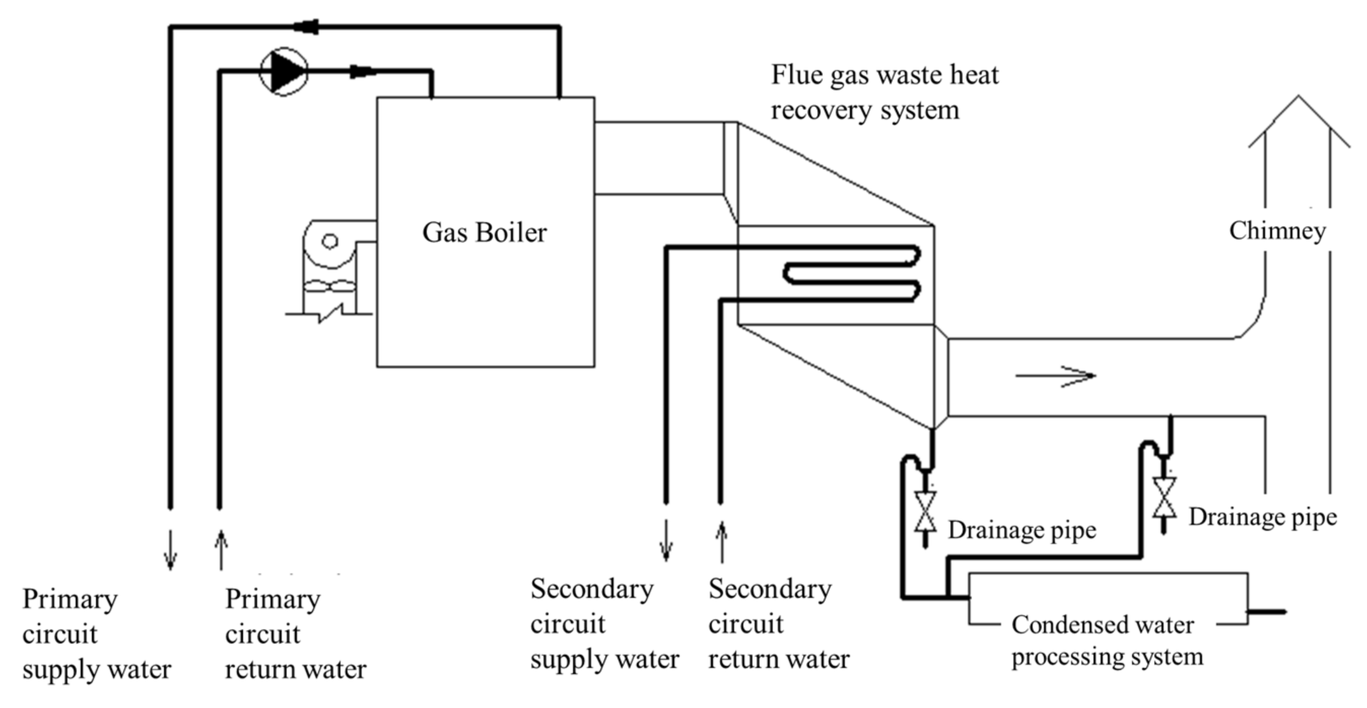
Three flue gas condensation waste heat recovery cases compared in this paper are designed for a gas boiler located in Xian, China [
5]. The system diagrams of the three cases are shown in
Figure 1,
Figure 2 and
Figure 3. Case 1 directly uses the waste heat of flue gas to heat the secondary circuit return water. Case 2 uses the waste heat of the flue gas to heat the water supplied to the direct-fired absorption heat pump. Case 3 makes cascading use of the waste heat of the flue gas to heat the secondary circuit return water and the water supplied to the direct-fired absorption heat pump. In these cases, the secondary circuit return water and the water supplied to the direct-fired absorption heat pump are the cooling water for the flue gas waste heat recovery system.
The system design parameters of the three cases are shown in
Table 2. The mass flow rate of the dry flue gas,
Ma, and the inlet temperature of the flue gas in the waste heat recovery system,
Tfg_in, are given according to the boiler. The temperatures of the cooling water are set in advance according to the requirement of the secondary circuit return water and the heat pump working condition. The heat released by the flue gas,
Qfg, is equal to the heat absorbed by the cooling water,
Qco.
where
Tfg_in is the inlet temperature of the flue gas in the waste heat recovery system,
Tfg_out is the outlet temperature of the flue gas in the waste heat recovery system,
din is the humidity ratio of the wet flue gas in the system inlet,
dout is the humidity ratio of the wet flue gas in the system outlet and
r is the latent heat of water vaporization.
where
Tco1_in is the inlet temperature of the secondary circuit return water,
Tco1_out is the outlet temperature of the secondary circuit return water,
Mco1 is the mass flow rate of the secondary circuit return water,
Tco2_in is the inlet temperature of the water supplied to the heat pump,
Tco2_in is the outlet temperature of the water supplied to the heat pump,
Mco2 is the mass flow rate of the water supplied to the heat pump and
C is the specific heat capacity of water.
According to Equations (7)–(9), Mco1 and Mco2 should be set properly and Tfg_out can be calculated. For each heat transfer stage, a sufficient heat transfer temperature difference needs to be ensured to avoid an excessive heat transfer area.
The mass flow rate of the condensed water,
Mcd, is given by:
Water removal rate,
θ, is given by:
According to Equations (10) and (11), based on the mass flow rate of the dry flue gas,
Ma, the mass flow rate of the condensed water,
Mcd, and the water removal rate,
θ, given in
Table 2, the humidity ratio of the wet flue gas,
din and
dout, used for calculating the exergy of the wet flue gas in Equation (1), could be obtained.
In reference [
5], the evaluation index is the thermal efficiency (TE) of the flue gas waste heat recovery system. TE is the ratio of heat absorbed by cooling water to the heat released by the flue gas when cooled to an ambient temperature, as given by Equation (12).
where
is the wet flue gas inlet enthalpy per unit mass of dry flue gas and
is the wet flue gas enthalpy per unit mass of dry flue gas at the reference state.
When the flue gas parameter is fixed, the lower the outlet temperature of the flue gas in the flue gas condensation waste heat recovery system and the higher the TE of flue gas waste heat utilization.
In this paper, the exergy analysis of the three flue gas condensation waste heat recovery cases for the same gas boiler can be directly compared with the thermal efficiency analysis results on the one hand. On the other hand, it can be analyzed and compared between cases so as to deeply discuss the meaning of the exergy analysis evaluation indexes proposed in this paper.
4. Results and Discussion
4.1. Calculation Results
Exergy analyses were performed for the above three cases and the calculation results are shown in
Table 3. The exergy analysis only focuses on the heat exchange progress to compare with the thermal efficiency analysis. For further exergy analysis, the entire system, especially the heat pump energy consumption, should be taken into account.
4.2. Influence Analysis of Condensed Water Exergy on EE
The comparison results of EE1 (ignoring the condensed water exergy) and EE2 (considering the condensed water exergy) are shown in
Figure 4. It can be seen in
Figure 4 that for the flue gas with a water vapor content of 10.7%, whether or not there was a consideration of the condensed water exergy had almost no effect on the calculated EE (<1%). Thus, the effect of condensed water exergy on EE can be ignored for wet flue gas with a water vapor content less than 10%.
4.3. Comparison of EE and EUR
Figure 5 shows the EE and EUR of the three cases. EE reflected the exergy output capacity of the heat exchange equipment and is related to the heat exchange temperature difference. If the heat exchange temperature difference is large, the exergy loss during the heat exchange process is larger and the EE is lower; otherwise, the EE is higher. The EUR reflected the comprehensive utilization degree of flue gas waste heat in different recovery cases. A high EUR not only requires a high grade of heat absorption by the cooling water, which is related to EE, but also requires a sufficient amount of heat absorption by the cooling water (when flue gas inlet parameters are fixed, the flue gas outlet temperature of the waste heat recovery system needs to be low enough), which is related to TE.
The waste heat recovery device in case 1 cooled the wet flue gas from 80 °C to 46 °C and heated the secondary circuit return water from 41 °C to 45.1 °C. As a result, the heat exchange temperature difference was small and the exergy loss during the heat exchange was small, so the EE was as high as 79.51%, that is, 79.51% of the exergy that was input into the system could be exported and utilized by the system. However, the designed outlet temperature of flue gas was 46 °C, much higher than that of case 2 (30 °C) and case 3 (34 °C). The TE of case 1 was the lowest, so the EUR was limited (53.62%). In case 2, the flue gas outlet temperature was the lowest, and the TE was the highest, reaching 86.5%. From the perspective of quantity, the flue gas waste heat is the most fully utilized. However, the waste heat recovery device cooled the wet flue gas from 80 °C to 30 °C and heated the water supplied to the heat pump from 20 °C to 25.2 °C. As a result, the heat exchange temperature difference was large, the exergy loss during heat exchange was large and the energy grade decreased seriously; the EE was the lowest among the three cases (27.28%). Therefore, even though cooling water absorbed the most amount of heat, it had a low grade, resulting in the lowest EUR (25.92%). Case 3 was between case 1 and case 2 in terms of both the total amount of waste heat used and energy grade lost during the heat exchange progress, and the final EUR reached 51%. The EUR is more suitable as a comprehensive index for comparing different waste heat recovery schemes, and EE could be used to judge whether the energy grade of heat exchange equipment was seriously decreased.
4.4. Comparison of TE and EUR
Figure 6 shows the comparison of the TE and EUR for the three cases. Case 2, with the highest TE, is the optimal case according to the thermal efficiency analysis method used in the past. However, it could be seen from the exergy analysis that in the recovery process, the grade of the flue gas waste heat in case 2 decreased seriously, and the EUR was the lowest among the three cases. TE can only reflect the utilization of the waste heat energy quantity, but not the utilization of the waste heat energy grade. The EUR reflects the recovery of the waste heat from the view of both quantity and quality.
To sum up, it is not comprehensive to simply use TE as the evaluation index of the waste heat recovery system. An exergy analysis of the flue gas condensate waste heat recovery system is still necessary even though the grade of the flue gas condensation waste heat is lower than that of other energy. When there are multiple waste heat users for flue gas condensation waste heat recovery, the users with a higher heat grade demand should be given priority according to the actual situation and following the principle of cascade utilization, and then the users with lower heat grade demand will reduce the flue gas to a lower temperature to complete the deep recovery. A flue gas condensation waste heat system should be comprehensively evaluated by both the thermal efficiency analysis and exergy analysis. EE is used to determine whether there is a serious energy grade decline in every utilization level and TE is used to determine whether the amount of waste heat energy is fully utilized. Finally, the EUR is used to comprehensively compare the “quality” and “quantity” of flue gas condensation waste heat utilization of different schemes.


