
Design and Analysis of Three Phase Axial Flux Permanent Magnet Machine with Different PM Shapes for Electric Vehicles

 , and
, and
Abstract
:1. Introduction
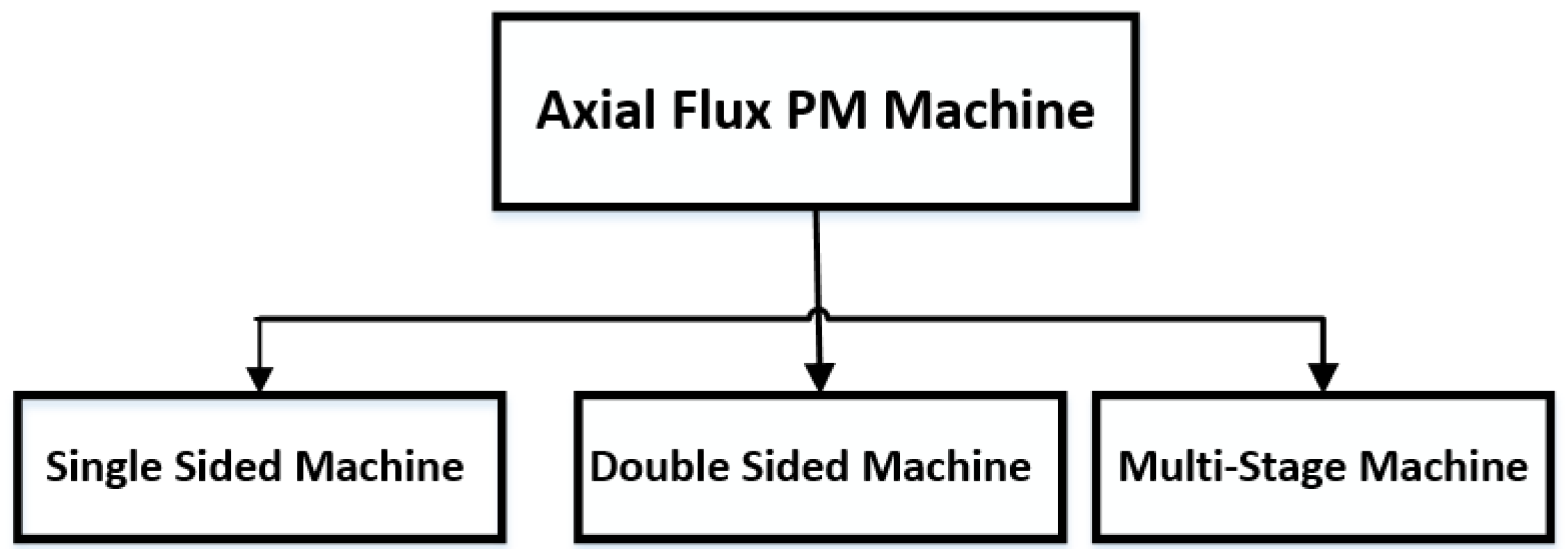
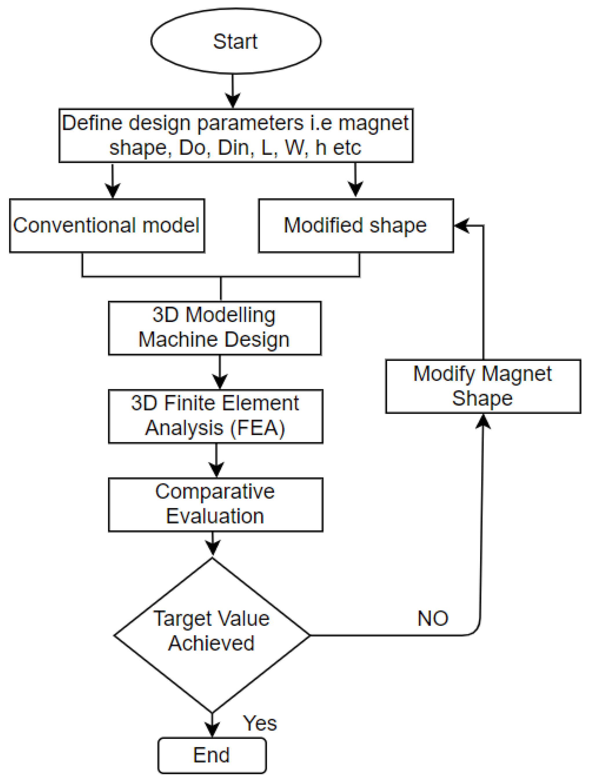
2. Design and Working Principle
3. Analysis Parameters
4. Electromagnetic Performance Analysis
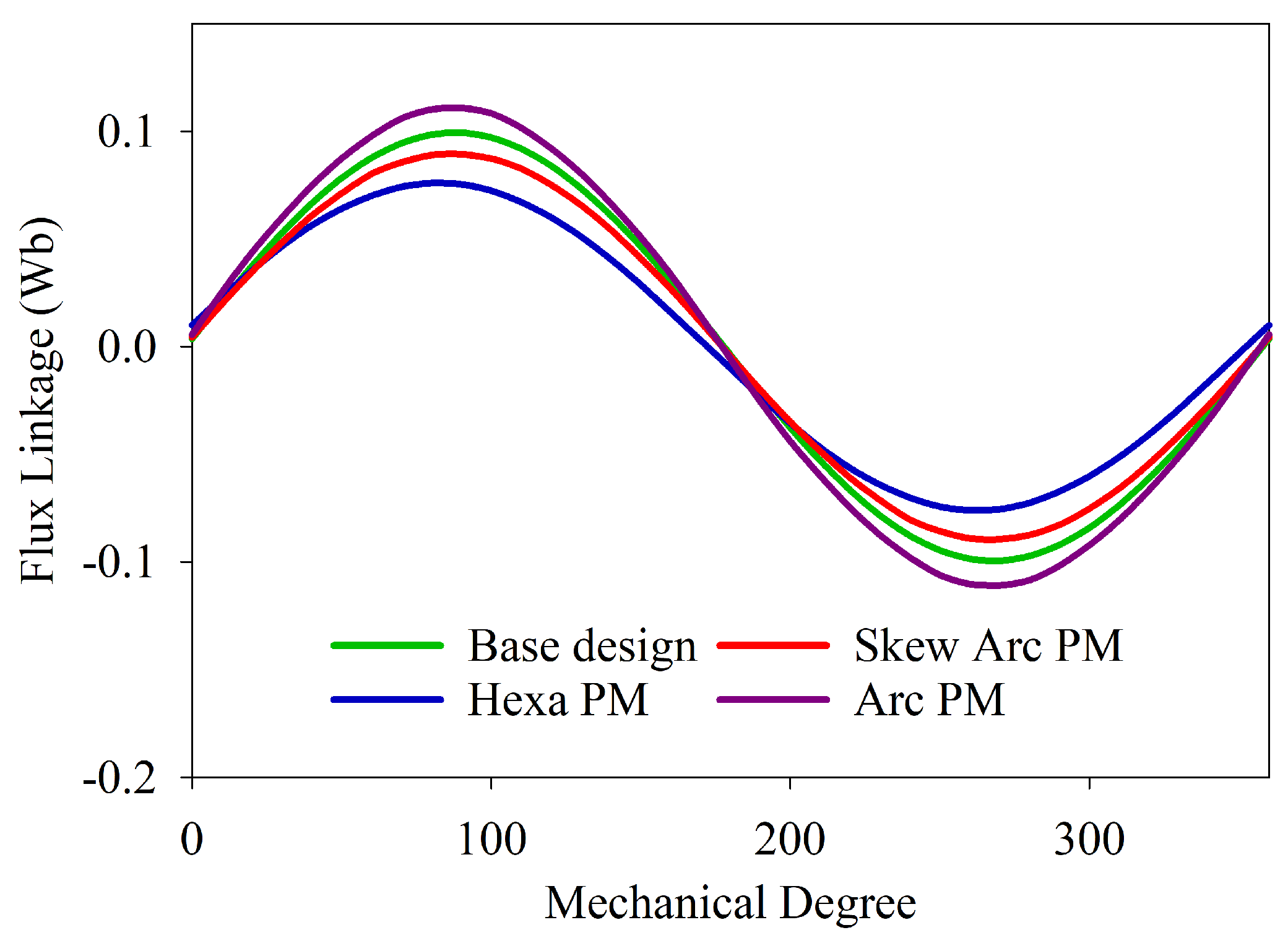
4.1. Flux Linkage
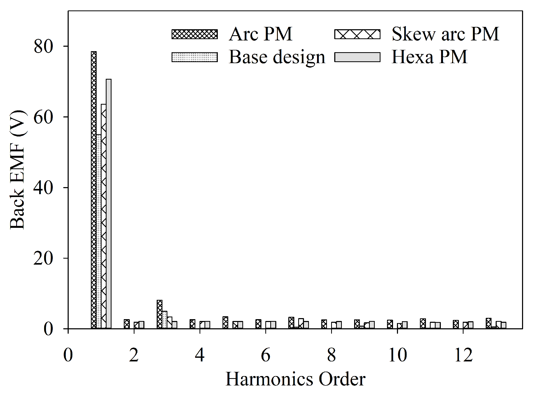
4.2. Back-EMF
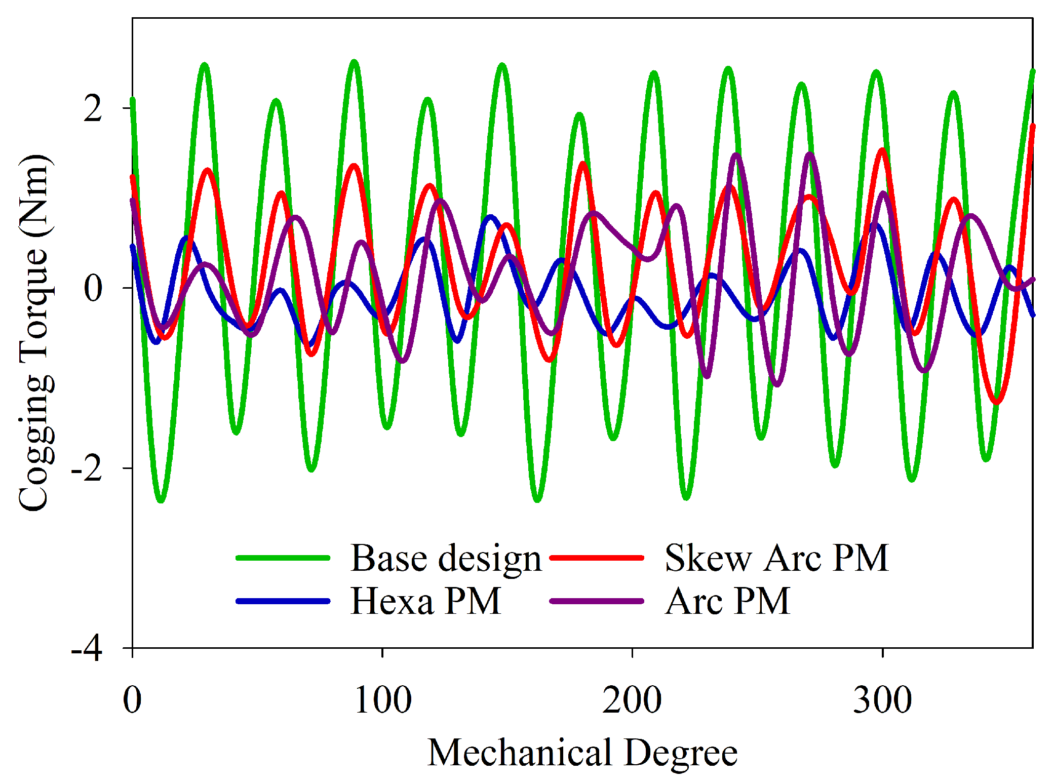
4.3. Cogging Torque
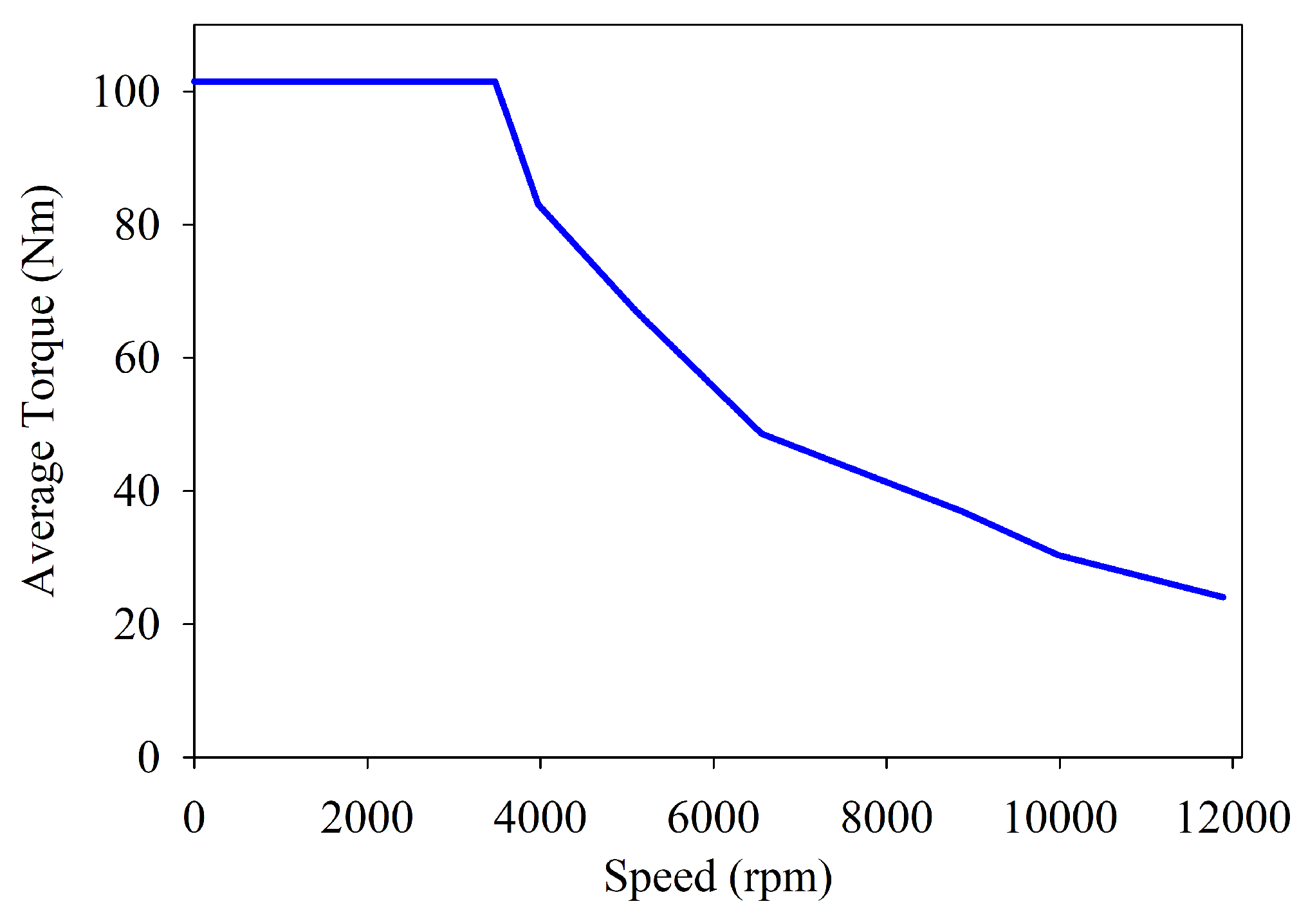
4.4. Average Torque
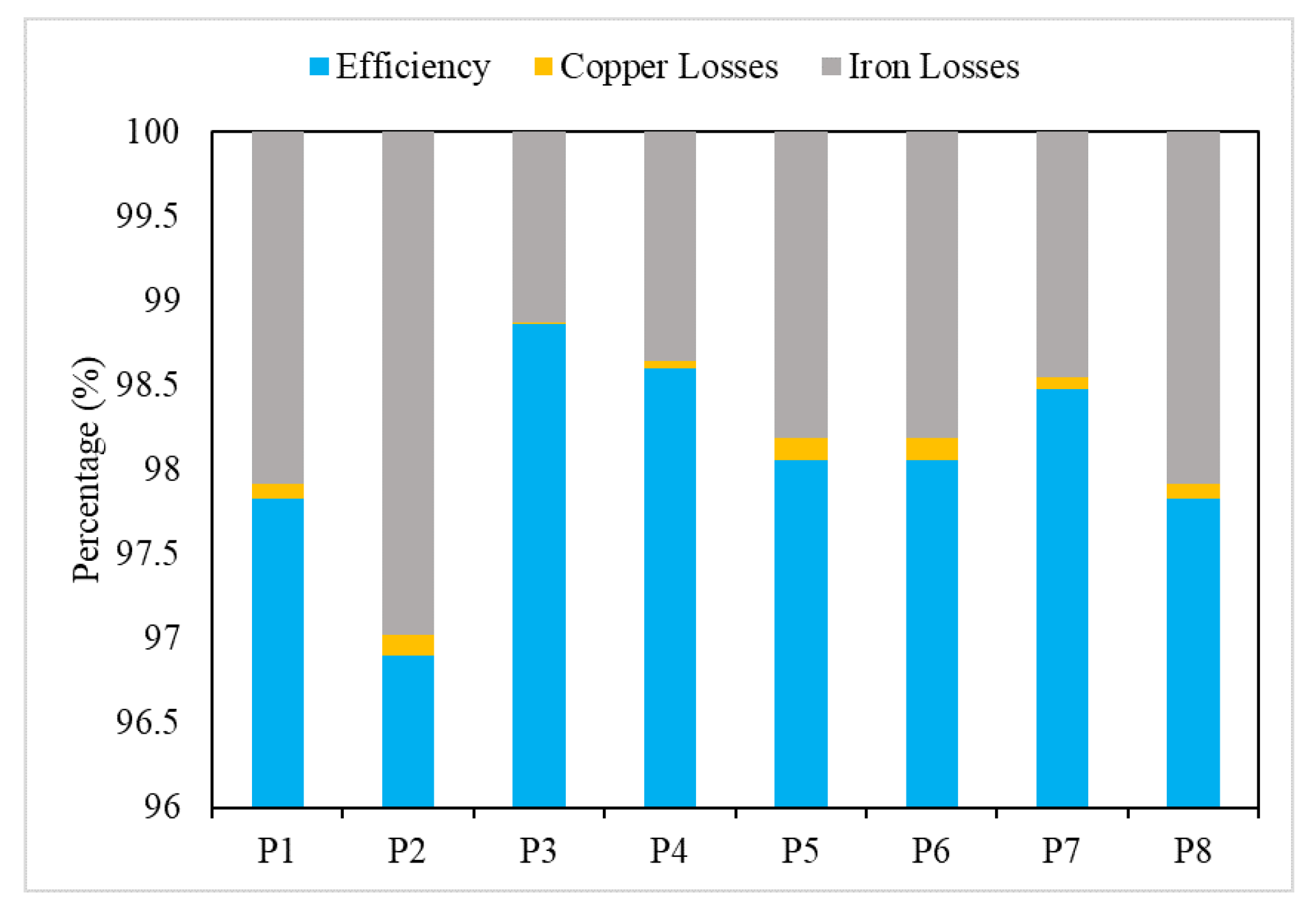
5. Efficiency Calculation
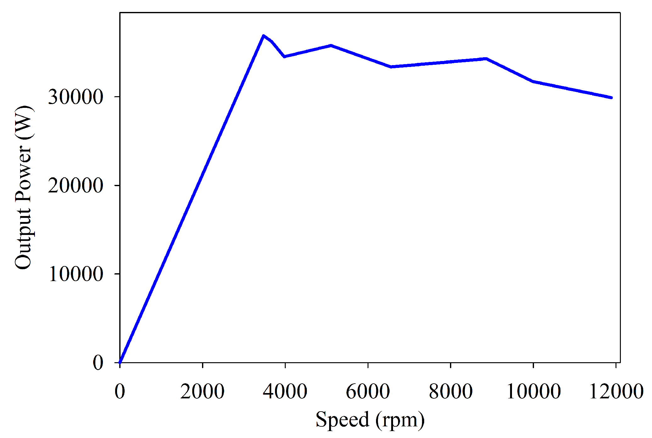
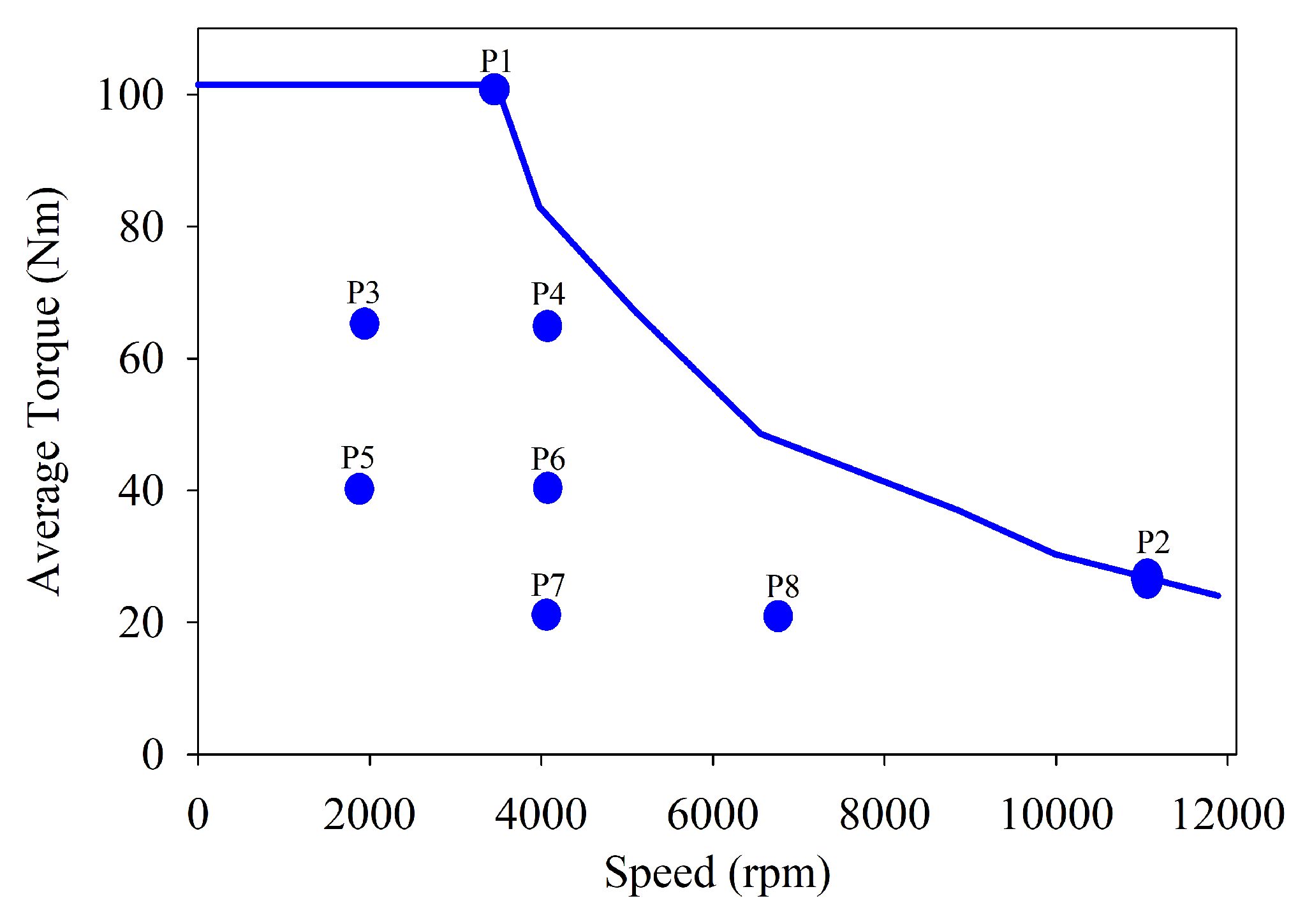
Power vs. Speed Curve
6. Performance Comparison
7. Conclusions
Author Contributions
Funding
Data Availability Statement
Conflicts of Interest
References
- Chattopadhyay, R.; Islam, M.S.; Boldea, I.; Husain, I. FEA Characterization of Bi-Axial Excitation Machine for Automotive Traction Applications. In Proceedings of the 2021 IEEE International Electric Machines & Drives Conference (IEMDC), Hartford, CT, USA, 17–20 May 2021; pp. 1–7. [Google Scholar]
- Mushid, F.; Dorrell, D. Review of axial flux induction motor for automotive applications. In Proceedings of the 2017 IEEE Workshop on Electrical Machines Design, Control and Diagnosis (WEMDCD), Nottingham, UK, 20–21 April 2017; pp. 146–151. [Google Scholar]
- Jussila, H.; Nerg, J.; Pyrhönen, J.; Parviainen, A. Concentrated winding axial flux permanent magnet motor for industrial use. In Proceedings of the XIX International Conference on Electrical Machines-ICEM 2010, Rome, Italy, 6–8 September 2010; pp. 1–5. [Google Scholar]
- Kim, J.H.; Li, Y.; Sarlioglu, B. Novel six-slot four-pole axial flux-switching permanent magnet machine for electric vehicle. IEEE Trans. Transp. Electrif. 2016, 3, 108–117. [Google Scholar] [CrossRef]
- Capponi, F.G.; De Donato, G.; Caricchi, F. Recent advances in axial-flux permanent-magnet machine technology. IEEE Trans. Ind. Appl. 2012, 48, 2190–2205. [Google Scholar] [CrossRef]
- Kahourzade, S.; Mahmoudi, A.; Ping, H.W.; Uddin, M.N. A comprehensive review of axial-flux permanent-magnet machines. Can. J. Electr. Comput. Eng. 2014, 37, 19–33. [Google Scholar] [CrossRef]
- Dwivedi, A.; Singh, S.K.; Srivastava, R.K. Analysis and performance evaluation of axial flux permanent magnet motors. IEEE Trans. Ind. Appl. 2017, 54, 1765–1772. [Google Scholar] [CrossRef]
- Zhao, J.; Quan, X.; Sun, X.; Li, J.; Lin, M. Design of a novel axial flux rotor consequent-pole permanent magnet machine. IEEE Trans. Appl. Supercond. 2020, 30, 1–6. [Google Scholar] [CrossRef]
- Capponi, F.G.; De Donato, G.; Rivellini, G.A.; Caricchi, F. Fractional-slot concentrated-winding axial-flux permanent-magnet machine with tooth-wound coils. IEEE Trans. Ind. Appl. 2014, 50, 2446–2457. [Google Scholar] [CrossRef]
- Husain, T.; Tekgun, B.; Sozer, Y.; Hamdan, M. Comparison of axial flux machine performance with different rotor and stator configurations. In Proceedings of the 2017 IEEE International Electric Machines and Drives Conference (IEMDC), Miami, FL, USA, 21–24 May 2017; pp. 1–8. [Google Scholar]
- Banchhor, D.K.; Dhabale, A. Design, modeling, and analysis of dual rotor axial flux induction motor. In Proceedings of the 2018 IEEE International Conference on Power Electronics, Drives and Energy Systems (PEDES), Chennai, India, 18–21 December 2018; pp. 1–6. [Google Scholar]
- Luk, P.C.K.; Abdulrahem, H.A.; Xia, B. Low-cost high-performance ferrite permanent magnet machines in EV applications: A comprehensive review. Etransportation 2020, 6, 100080. [Google Scholar] [CrossRef]
- Taran, N.; Rallabandi, V.; Ionel, D.M.; Zhou, P.; Thiele, M.; Heins, G. A systematic study on the effects of dimensional and materials tolerances on permanent magnet synchronous machines based on the IEEE Std 1812. IEEE Trans. Ind. Appl. 2018, 55, 1360–1371. [Google Scholar] [CrossRef]
- Si, J.; Zhang, T.; Nie, R.; Gan, C.; Hu, Y. Comparative Study of Dual-Rotor Slotless Axial-Flux Permanent Magnet Machines with Equidirectional Toroidal and Conventional Concentrated Windings. IEEE Trans. Ind. Electron. 2022, 70, 1216–1228. [Google Scholar] [CrossRef]
- Liu, Y.; Zhang, Z.; Wang, C.; Geng, W.; Wang, H. Electromagnetic performance analysis of a new hybrid excitation synchronous machine for electric vehicle applications. IEEE Trans. Magn. 2018, 54, 1–4. [Google Scholar] [CrossRef]
- Usman, A.; Doiphode, N.T.; Rajpurohit, B.S. Stator Winding Faults investigation in Permanent Magnet Synchronous Motor using Motor Signatures: Part I. In Proceedings of the 2019 International Conference on Electrical Drives & Power Electronics (EDPE), The High Tatras, Slovakia, 24–26 September 2019; pp. 160–168. [Google Scholar]
- Chowdhury, A.; Das, S.; Tsuda, T.; Saito, N.; Saha, S.; Sozer, Y. Design and Comprehensive Performance Analysis of Transverse Flux and Axial Flux Topologies For Permanent Magnet Synchronous Machines. In Proceedings of the 2021 IEEE Energy Conversion Congress and Exposition (ECCE), Vancouver, BC, Canada, 10–14 October 2021; pp. 3957–3962. [Google Scholar]
- Huang, R.; Song, Z.; Zhao, H.; Liu, C. Overview of Axial-Flux Machines and Modeling Methods. IEEE Trans. Transp. Electrif. 2022, 8, 2118–2132. [Google Scholar] [CrossRef]
- Khan, S.; Bukhari, S.S.H.; Ro, J.S. Design and analysis of a 4-kW two-stack coreless axial flux permanent magnet synchronous machine for low-speed applications. IEEE Access 2019, 7, 173848–173854. [Google Scholar] [CrossRef]
- Zhang, B.; Seidler, T.; Dierken, R.; Doppelbauer, M. Development of a yokeless and segmented armature axial flux machine. IEEE Trans. Ind. Electron. 2015, 63, 2062–2071. [Google Scholar] [CrossRef]
- Spooner, E.; Chalmers, B. ‘TORUS’: A slotless, toroidal-stator, permanent-magnet generator. IEE Proc. B (Electr. Power Appl.) 1992, 139, 497–506. [Google Scholar] [CrossRef] [Green Version]
- Chang, J.; Wang, C. Electromagnetic thermal coupling analysis for a novel cooling system of an axial flux hub motor. IET Electr. Power Appl. 2022, 16, 421–433. [Google Scholar] [CrossRef]
- Li, J.; Lu, Y.; Cho, Y.H.; Qu, R. Design, analysis, and prototyping of a water-cooled axial-flux permanent-magnet machine for large-power direct-driven applications. IEEE Trans. Ind. Appl. 2019, 55, 3555–3565. [Google Scholar] [CrossRef]
- Taqavi, O.; Taghavi, N. Development of a mixed solution of Maxwell’s equations and magnetic equivalent circuit for double-sided axial-flux permanent magnet machines. IEEE Trans. Magn. 2021, 57, 1–11. [Google Scholar] [CrossRef]
- Amin, S.; Khan, S.; Bukhari, S.S.H. A comprehensive review on axial flux machines and its applications. In Proceedings of the 2019 2nd International Conference on Computing, Mathematics and Engineering Technologies (iCoMET), Sukkur, Pakistan, 30–31 January 2019; pp. 1–7. [Google Scholar]
- Mirzahosseini, R.; Darabi, A.; Assili, M. Magnet shifting for back EMF improvement and torque ripple reduction of a TORUS-type nonslotted axial flux permanent magnet machine. Int. Trans. Electr. Energy Syst. 2020, 30, e12293. [Google Scholar] [CrossRef]
- Muljadi, E.; Butterfield, C.P.; Wan, Y.H. Axial-flux modular permanent-magnet generator with a toroidal winding for wind-turbine applications. IEEE Trans. Ind. Appl. 1999, 35, 831–836. [Google Scholar] [CrossRef] [Green Version]
- Caricchi, F.; Crescimbini, F.; Di Napoli, A. Prototype of innovative wheel direct drive with water-cooled axial-flux PM motor for electric vehicle applications. In Proceedings of the Applied Power Electronics Conference. APEC’96, San Jose, CA, USA, 3–7 March 1996; Volume 2, pp. 764–770. [Google Scholar]
- Chang, J.; Fan, Y.; Wu, J.; Zhu, B. A Yokeless and Segmented Armature Axial Flux Machine With Novel Cooling System for In-Wheel Traction Applications. IEEE Trans. Ind. Electron. 2020, 68, 4131–4140. [Google Scholar] [CrossRef]
- Cetin, E.; Daldaban, F. Analyzing the profile effects of the various magnet shapes in axial flux PM motors by means of 3D-FEA. Electronics 2018, 7, 13. [Google Scholar] [CrossRef] [Green Version]
- Li, T.; Zhang, Y.; Liang, Y.; Yang, Y.; Jiao, J. Magnet eddy-current losses reduction of an axial-flux in-wheel motor with amorphous magnet metal. Int. J. Appl. Electromagn. Mech. 2021, 65, 431–450. [Google Scholar] [CrossRef]
- Usman, H.; Ikram, J.; Alimgeer, K.S.; Yousuf, M.; Bukhari, S.S.H.; Ro, J.S. Analysis and optimization of axial flux permanent magnet machine for cogging torque reduction. Mathematics 2021, 9, 1738. [Google Scholar] [CrossRef]
- Cetin, E.; Daldaban, F. Reducing torque ripples of the axial flux PM motors by magnet stepping and shifting. Eng. Technol. Appl. Sci. Res. 2018, 8, 2385–2388. [Google Scholar] [CrossRef]
- Baig, M.A.; Ikram, J.; Iftikhar, A.; Bukhari, S.S.H.; Khan, N.; Ro, J.S. Minimization of cogging torque in axial field flux switching machine using arc shaped triangular magnets. IEEE Access 2020, 8, 227193–227201. [Google Scholar] [CrossRef]


| Parameter | Value |
|---|---|
| Axial Length (L) | 60 mm |
| Outer Radius () | 130 mm |
| Inner Radius () | 65 mm |
| Airgap | 1 mm |
| Stator Height (h) | 38 mm |
| Yoke Height | 12 mm |
| Yoke Length | 43 mm |
| PM Height (W) | 5 mm |
| Number of Turns | 10 |
| Filling factor | 0.75 |
| Parameters | Base Design | Hexagonal Shaped | Skew Arc Shaped | Arc Shaped |
|---|---|---|---|---|
| (Wb) | 0.1165 | 0.0848 | 0.1066 | 0.1322 |
| Flux-THD (%) | 4.42 | 1.67 | 2.69 | 3.06 |
| p-p (Nm) | 4.72 | 1.31 | 2.75 | 2.45 |
| Back-EMF-THD (%) | 17 | 12 | 13 | 9 |
| (Nm) | 90.36 | 70.79 | 83.61 | 101.12 |
| (Nm) | 4.44 | 3.63 | 3.55 | 6.61 |
| ratio | 14.74 | 15.37 | 12.73 | 18.75 |
| (kNm/) | 40.23 | 32.46 | 39.78 | 50.38 |
| Weight (Kg) | 16.90 | 15.52 | 16.89 | 16.35 |
| Power (KW) | 32.85 | 25.74 | 30.40 | 36.89 |
| Efficiency (%) | 96 | 84.5 | 96.5 | 98.6 |
Publisher’s Note: MDPI stays neutral with regard to jurisdictional claims in published maps and institutional affiliations. |
© 2022 by the authors. Licensee MDPI, Basel, Switzerland. This article is an open access article distributed under the terms and conditions of the Creative Commons Attribution (CC BY) license (https://creativecommons.org/licenses/by/4.0/).
Share and Cite
Islam, Z.; Khan, F.; Ullah, B.; Milyani, A.H.; Ahmed Azhari, A. Design and Analysis of Three Phase Axial Flux Permanent Magnet Machine with Different PM Shapes for Electric Vehicles. Energies 2022, 15, 7533. https://doi.org/10.3390/en15207533
Islam Z, Khan F, Ullah B, Milyani AH, Ahmed Azhari A. Design and Analysis of Three Phase Axial Flux Permanent Magnet Machine with Different PM Shapes for Electric Vehicles. Energies. 2022; 15(20):7533. https://doi.org/10.3390/en15207533
Chicago/Turabian StyleIslam, Ziaul, Faisal Khan, Basharat Ullah, Ahmad H. Milyani, and Abdullah Ahmed Azhari. 2022. "Design and Analysis of Three Phase Axial Flux Permanent Magnet Machine with Different PM Shapes for Electric Vehicles" Energies 15, no. 20: 7533. https://doi.org/10.3390/en15207533