Article

A Harmonic Suppression SVPWM Strategy for the Asymmetric Six-Phase Motor Fed by Two-Level Six-Phase VSI Operating in the Overmodulation Region

1
College of Electrical and Information Engineering, Hunan University, Changsha 410082, China
2
College of Electrical and Information Engineering, Hunan University of Technology, Zhuzhou 412007, China
3
Faculty of Engineering, University of Bristol, Queens Road, Bristol BS8 1QU, UK
*
Author to whom correspondence should be addressed.
Energies 2022, 15(20), 7589; https://doi.org/10.3390/en15207589
Submission received: 24 July 2022 / Revised: 17 September 2022 / Accepted: 22 September 2022 / Published: 14 October 2022
(This article belongs to the Section F3: Power Electronics)

Abstract

:
For the asymmetric six-phase motor fed by a two-level six-phase voltage source inverter (VSI), when the modulation index is less than 0.5774, the motor operates in the linear region, and the harmonics in the Z1 − Z2 subspace can be suppressed to zero. When the modulation index is beyond 0.5774 and less than 0.6221, the motor operates in overmodulation regions, and the harmonics in the Z1 − Z2 subspace cannot be suppressed to zero. To minimize the harmonics in the Z1 − Z2 subspace for these regions, a harmonic suppression strategy, namely, harmonic suppression overmodulation strategy (HSOS), is proposed in this paper. The lower-order harmonics of the Z1 − Z2 subspace, namely, the 5th, 7th, 17th and 19th, are considered. Compared with the traditional four-vector overmodulation strategy (TFOS), the content of the 5th harmonic is reduced by about 20%, and the total harmonic distortion (THDZ1Z2) of these four kinds of harmonics is reduced by about 21% in the proposed HSOS. Finally, the simulation and experiment are carried out to verify the effectiveness of the proposed strategy.

Graphical Abstract

1. Introduction

Compared with traditional three-phase machines, multi-phase machines have many outstanding advantages, such as low-voltage high-power output, less torque ripple, favourable fault tolerance characteristics and higher reliability at the system level. They are widely used in various applications, such as electric locomotive traction, shipboard power propulsion and wind power generation [1,2]. The asymmetric six-phase motor in which two sets of three-phase windings are shifted by 30 electrical degrees is widely studied [3].
In recent decades, various technologies of the motor have been quickly developed. Some research is on the controller to improve the mechanical performance of the motor [4,5]. A controller of DC-link voltage of the three-phase PWM rectifier has been proposed in [4]. In this controller, an Artificial Bee Colony (ABC) optimization method is used to optimize the type-2 fuzzy neural network (T2FNN) controller. As a result, the proposed controller has a better dynamic response than the traditional T2FNN controller. Based on the proportional + derivative type-2 fuzzy neural network (PD-T2FNN), a controller is proposed in [5] for DC-link voltage control of the PWM rectifier. Compared with traditional PD, proportional + integral, and T2FNN controllers, the proposed controller has superior performance in the transient and steady-state responses under various working conditions. The pulse width modulation (PWM) strategy is another research hotspot for motor drive systems, which directly influences the inverter system efficiency and the quality of the output waveform [6,7]. The overmodulation PWM strategy is widely applied in electric vehicles, mining equipment and other motor drive fields. For example, an overmodulation control strategy has been used in the medium-speed range for motor drive control of the TOYOTA hybrid system II (THS II), and the output of the shaft torque has been increased by a maximum of approximately 30% in this range [8]. For a single-phase inverter operating in the overmodulation region, an improved SPWM method is proposed in [9] to eliminate the third harmonic. Thus, the total harmonic distortion is reduced and current quality is improved. For three-phase motors, an overmodulation space vector pulse width modulation (SVPWM) strategy based on Fourier series expansion of the reference voltage is proposed in [10], and maximum utilization of the dc-link voltage can be achieved. However, the calculation amount is large. Another SVPWM strategy based on the superposition principle for a three-phase motor operating in the overmodulation range is developed in [11]. This strategy does not need to calculate the control angle or the hold angle, and it is easy to implement digitally. However, the voltage harmonic components in the overmodulation region are large. Modulation functions of carrier-based PWM which are equivalent to this SVPWM strategy are investigated in [12]. However, these modulation functions are based on the superposition principle and are not universal. Ref. [13] has proposed a method that combines Space-Vector Modulated Direct Torque Control (DTC-SVM) and conventional DTC. In the linear region, the DTC-SVM is used, which provides low THD and low torque ripple, while in the overmodulation region, the conventional DTC is applied. The transition between these two methods is smooth, and the DC bus voltage is fully employed. In [14], an SVPWM strategy exploiting the Lagrangian method to minimize the harmonic voltage in the overmodulation range is proposed for a five-phase voltage source inverter (VSI). However, this method adopts suboptimal solutions under specific conditions instead of the optimal solution. The comprehensive relationship between the carrier-based PWM and SVPWM techniques for a five-phase motor operating in the linear modulation range is explained in [15]. For six-phase motors, there are two major models [16]: the double synchronous reference frame (double d-q) model [17,18] and the vector space decomposition (VSD) model [19,20]. In the double d-q model, the SVPWM strategy is similar to the traditional three-phase VSI. In [17], the proposed current control scheme based on the double d-q model uses four identical PI regulators for all current loops. In this way, the two sets of three-phase stator currents are independently controlled and kept balanced. However, the decoupling voltage required by this method is complex. An indirect field-oriented control (FOC) scheme for a six-phase induction machine is proposed in [18]. The unbalanced current between the two sets of three-phase windings is eliminated, and this scheme is applicable to a six-phase machine with any arbitrary angle of displacement between the two sets. However, many sensors are used in this method, which increases the cost of industrial application. For the VSD model, two-vector SVPWM is the simplest modulation strategy, which will generate many 6n ± 1 (n = 1, 3, 5, …) harmonic voltage components [19]. The commonly used SVPWM strategies are four-vector modulation techniques. An SVPWM strategy synthesizing the reference voltage vector using four adjacent large voltage vectors (4L) is proposed in [20], which can keep the harmonics in the Z1 − Z2 subspace at a minimum level within the linear modulation range. However, the harmonic distortion factor of this strategy has not been studied. Based on [20], several new discontinuous SVPWM strategies for six-phase VSIs have been proposed, and the harmonic current of each strategy has been completely studied [21]. The results demonstrate that the performance of these strategies is affected by the parameter kσxy, which is defined as the ratio of the total (α − β) referred-to-stator leakage inductance to the (Z1 − Z2) leakage inductance. However, only the 4L strategy has been analysed, not other strategies; for example, the two large vectors plus two medium vectors (2L + 2M) strategy. The double zero-sequence injection PWM method is studied for the asymmetrical six-phase motors in [22]. This method can reduce the calculation amount, but the flux harmonic distortion factor (HDF) in the Z1 − Z2 subspace is higher than that in the SVPWM strategies. Using the SVPWM method, a zero CMV (ZCMV) strategy is proposed in [23] to eliminate the common mode voltage (CMV) for asymmetric six-phase motors. In this strategy, the turn-on/off moment of each phase is shifted, and the peak value of total CMV is suppressed to 0 in theory. To reduce the CMV for asymmetric six-phase motors, three SVPWM schemes, namely, CMV2, CMV3, and DCMV3, are proposed in [24]. Although their CMV suppression effects are the same, their harmonic performances are different. The DCMV3 has better harmonic performance in the high modulation region for leakage coupling coefficients ξ = 1 to 2. If ξ = 6.2, the CMV2 performs better in the higher modulation region, while the DCMV3 generates superior quality waveforms in the lower modulation region. A modified SVPWM technique that divides the α − β subspace into 24 sectors is proposed in [25]. It provides lower current THD, but it only focuses on the linear range and does not involve the overmodulation range.
When a motor operates in the overmodulation region, low-order voltage harmonic components in the Z1 − Z2 subspace are unavoidable. However, harmonic impedance in the Z1 − Z2 subspace is only composed of the stator resistance and leakage inductance; thus, even low-level harmonic voltages can induce large harmonic currents. Therefore, it is necessary to suppress the harmonic components in the Z1 − Z2 subspace. In [26], a general n-phase SVPWM technique is proposed for overmodulation regions, which forces the zero-vector duty cycle δ0 to zero for the entire sector, and it effectively suppresses voltage harmonic components in the Z1 − Z2 subspace. However, this technique is only applicable to odd n. An SVPWM strategy for six-phase voltage source-inverter-fed six-phase split-phase induction motors is presented in [27]. The approach is based on three-phase space vector modulators that can be operated in both the linear and overmodulation regions. However, it does not consider harmonic suppression in the Z1 − Z2 subspace. Through extending the three-phase VSI overmodulation method to the six-phase VSIs, Ref. [28] has proposed an SVPWM strategy that divides the overmodulation regions into two sections. In section I, the amplitude of reference voltage is proportional to the modulation index. In section II, due to the phase correction algorithm, the distortion of phase voltage is reduced. Although the traditional four-vector overmodulation strategy (TFOS) [29] can suppress the harmonic voltage components in the overmodulation range, the harmonic component content is still quite large and will be compared with the proposed strategy.
The control objective of this paper is to synthesize the reference voltage in the αβ subspace and simultaneously minimize the harmonic components in the Z1 − Z2 subspace when a six-phase asymmetric motor fed by two-level six-phase VSI operates in the overmodulation range. A novel SVPWM strategy, namely, harmonic suppression overmodulation strategy (HSOS), is proposed in this paper, which can effectively achieve this objective. The main innovation is that the optimization models consisting of an objective function and constraint conditions are built, and the external point method is adopted to minimize the harmonics in the Z1 − Z2 subspace. The main contribution is that the proposed HSOS can reduce the content of the 5th harmonic by about 20% and the THDZ1Z2 of the four harmonics (namely, the 5th, 7th, 17th and 19th) by about 21% when it is compared with the TFOS. The rest of this paper is organized as follows: The basic theory of the six-phase two-level VSI model is described in Section 2. In Section 3, the existing method TFOS is briefly introduced at first, and then the proposed HSOS is deduced in detail. The simulation and experiment are carried out in Section 4 and Section 5, respectively. In these two sections, harmonic content of line voltage and current in these two strategies are compared, and the validity of the proposed HSOS is verified.

2. The Six-Phase Two-Level VSI Model

The typical topology of an asymmetric six-phase motor with two isolated neutral points fed by six-phase two-level VSI is shown in Figure 1.
It is known from vector space decomposition (VSD) theory that the 64 switching states of a six-phase VSI can be mapped into three mutually perpendicular subspaces, i.e., the α − β, Z1 − Z2 and O1 − O2 subspaces. The α − β subspace mainly contains the fundamental and 12K ± 1 (K = 1, 2, 3, …) harmonics, and the Z1−Z2 subspace mainly contains the 6K ± 1 (K = 1, 3, 5, …) harmonics. In the O1 − O2 subspace, the 6K ± 3 (K = 1, 3, 5, …) harmonics are contained. However, when the neutral points N and N’ are isolated from each other, all the voltage vectors of the O1 − O2 subspace are mapped to the origin.
The voltage vectors corresponding to each switching state in the α − β subspace and Z1 − Z2 subspace are determined by (1) and (2), respectively.
V α β = 1 3 U d c ( S A + S B a 4 + S C a 8 + S X a + S Y a 5 + S Z a 9 )
V Z 1 Z 2 = 1 3 U d c ( S A + S B a 8 + S C a 4 + S X a 5 + S Y a + S Z a 9 )  
where a = e j 30 ° , and SK (K = A, B, C, X, Y, Z) is the switching state of each branch of the inverter. SK = 1 means that the top transistor of leg K is ON and the bottom is OFF. The opposite is true when SK = 0. The corresponding switching states of the six branches constitute a set of binary numbers, which, from high to low, are A, B, C, X, Y and Z. Each set of binary numbers corresponds to an octal number that labels a voltage vector. Therefore, voltage vector diagrams of the α − β subspace and the Z1 − Z2 subspace can be obtained, as shown in Figure 2. Each subspace contains 60 effective voltage vectors and 4 zero-voltage vectors. These 60 effective voltage vectors can be classified into four groups according to their amplitudes, i.e., large vector VL, medium vector VM, small vector VS and extra small vector VE. The amplitude of each group of vectors is shown in Table 1. As mentioned previously, the inverter output voltage vector in its natural reference frame can be mapped into three orthogonal planes, namely, the α − β, Z1 − Z2 and O1 − O2 subspaces, by (3).
[ V α V β V Z 1 V Z 2 V O 1 V O 2 ] T = T 6 1 [ V A V B V C V X V Y V Z ] T
where
T 6 1 = 1 3 [ 1 1 2 1 2 3 2 3 2 0 0 3 2 3 2 1 2 1 2 1 1 1 2 1 2 3 2 3 2 0 0 3 2 3 2 1 2 1 2 1 1 1 1 0 0 0 0 0 0 1 1 1 ]
The modulation index m is defined as the ratio of the phase voltage fundamental amplitude |V1| and the dc-link voltage Udc:
m = | V 1 | U d c

3. The Proposed HSOS

3.1. The Traditional Four-Vector Overmodulation Strategy (TFOS)

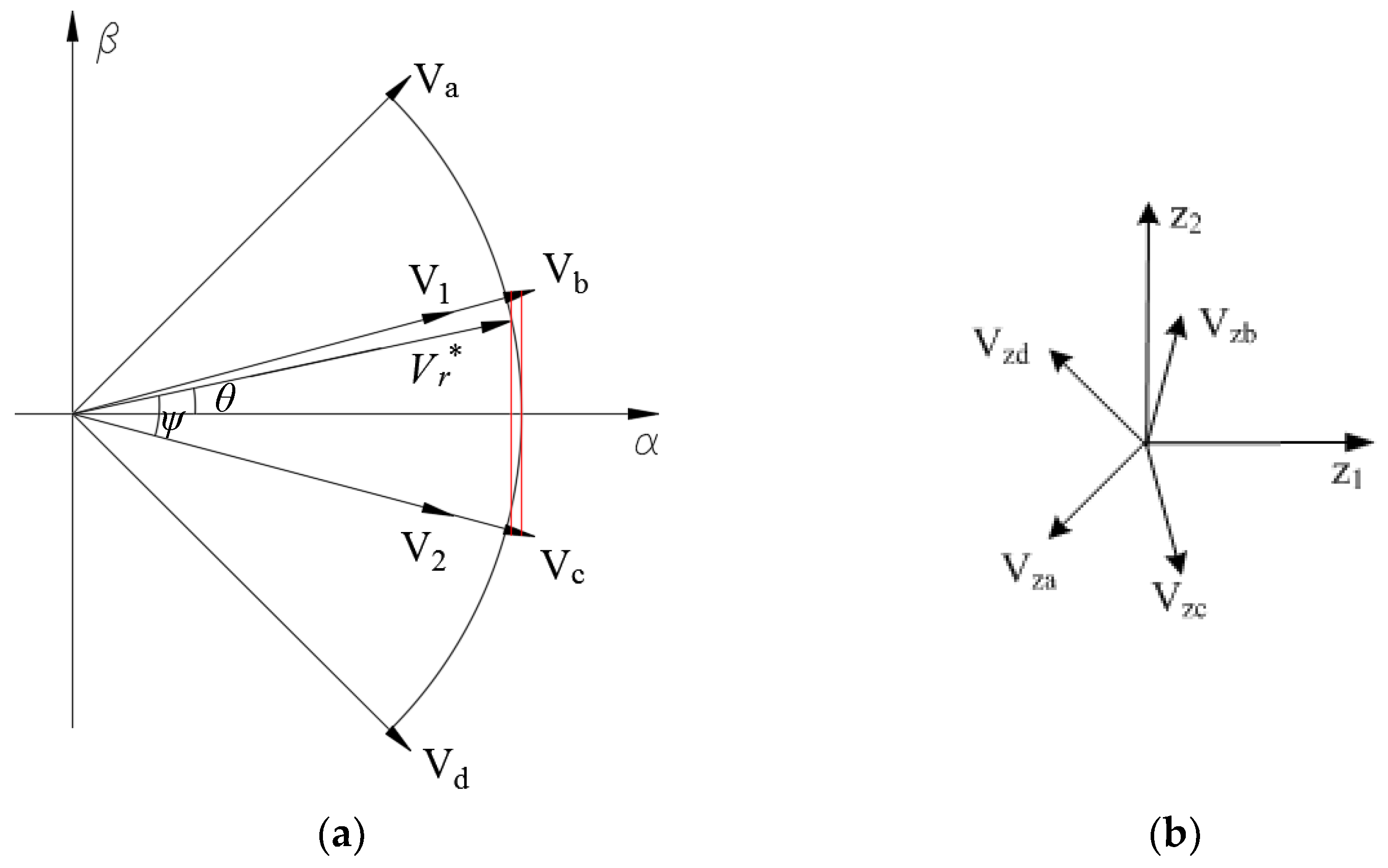
For the four-vector SVPWM strategy, when the modulation index is less than 0.5774, harmonic voltage components in the Z1 − Z2 subspace can be suppressed to zero. However, when it is between 0.5774 and 0.6221, the harmonic components in the Z1 − Z2 subspace cannot be suppressed to zero [29]. The TFOS is one of the strategies used in this overmodulation range. According to this strategy, the reference voltage vector Vr* is synthesized from four adjacent large voltage vectors, and their duty cycles change with the angle change of Vr*. To reduce the harmonics, Vr* is regulated to fall on the boundary of a regular dodecagon by adjusting the value of parameter a, as shown in (6). Figure 3 shows the TFOS diagram of voltage vectors where two intermediate vectors V1 and V2 are defined. Vector V1 is synthesized by Va, Vb and Vc, and its position angle is the same as that of Vb. The duty cycle of V1 is defined as η1, and the duty cycle of Vb is a·η1. Vector V2 is synthesized from Vb, Vc and Vd, and its position angle is the same as that of Vc, as shown in Figure 3. The duty cycle of V2 is defined as η2, and the duty cycle of Vc is a·η2. According to the volt-second balance rule, (7) can be obtained. Therefore, the duty cycle of each vector can be derived, as shown in (8).
a = 12 | V r * | U d c cos θ 2 3 3
{ η 2 = ( 2 + 6 ) 2 cos θ sin ( 30 ° ψ ) η 1 = ( 2 + 6 ) 2 cos θ sin ψ
{ η a = 0.5 ( 1 a ) η 1 η b = 0.5 ( 1 a ) η 2 + a η 1 η c = a η 2 + 0.5 ( 1 a ) η 1 η d = 0.5 ( 1 a ) η 2
It is worth noting that this strategy suppresses the harmonics only to a certain extent, and the harmonic components are still relatively large.

3.2. The Proposed HSOS Strategy

In the proposed HSOS strategy, the same four adjacent large voltage vectors are exploited to synthesize Vr*, and the α − β subspace is also divided into 12 sectors, as shown in Figure 2a. Assuming that Vr* is located in the first sector, its neighbouring four large voltage vectors are Va, Vb, Vc and Vd, and this sector is divided into four regions (Z1, Z2, Z3 and Z4), as shown in Figure 4.
Each region will be studied in detail as follows, where the duty cycle of every vector and the borders of each region are deduced.

3.2.1. Modulation in Linear Region Z1

According to the volt-second balance rule, (9) can be obtained.
[ V a α V b α V c α V d α V a β V b β V c β V d β V a z 1 V b z 1 V c z 1 V d z 1 V a z 2 V b z 1 V c z 2 V d z 2 ] [ η a η b η c η d ] = [ V α V β V z 1 V z 2 ]
When the modulation index is less than 0.5774; the harmonic voltage components in the Z1 − Z2 subspace can be suppressed to zero, and Vr* is located in the Z1 region of Figure 4. In this region, harmonic voltage components can be expressed as (10).
{ V z 1 = 0 V z 2 = 0
Substituting (10) into (9), the duty cycle of each effective vector can be expressed as (11).
[ η a η b η c η d ] T = C 1 [ V α V β 0 0 ] T
where
C 1 = [ V a α V b α V c α V d α V a β V b β V c β V d β V a z 1 V b z 1 V c z 1 V d z 1 V a z 2 V b z 1 V c z 2 V d z 2 ] 1 = [ 0.2321 0.866 3.2321 0.866 0.6340 0.6340 2.3660 2.3660 0.6340 0.6340 2.3660 2.3660 0.2321 0.866 3.2321 0.866 ]
Therefore, the duty cycle of the zero-voltage vector is obtained, as shown in (13).
η 0 = 1 ( η a + η b + η c + η d )
On the border of the linear region, the duty cycle of zero vector is zero, and both values of the harmonic voltages Vz1 and Vz2 are also zero. In addition, the synthesized voltage mapping into the α and β axes must equal to V α and V β , respectively. So, there are five constraint equations and four duty cycles which are the functions of V α or V β . The coefficient matrix consists of five rows and four columns, which is not convenient to calculate. Therefore, those five constraint equations are divided into two parts, shown as (14) and (15).
[ 1 1 1 1 V a β V b β V c β V d β V a z 1 V b z 1 V c z 1 V d z 1 V a z 2 V b 21 V c z 2 V d z 2 ] [ η a η b η c η d ] = [ 1 V β 0 0 ]
According to (14), the duty cycles which are functions of V β are obtained. Then, the constraint condition of V α is realized by (15).
V α = [ V a α V b α V c α V d α ] [ η a η b η c η d ] T
V α is a function of V β , which consists of the linear region border function. Substituting the specific value of each vector into (15), the border function VαL12 can be expressed as
L 12 : V α L 12 = 0.5774
Line L12 intersects with the lines of vectors Vc and Vb at points P1 and P2, respectively.
P 1 : { V α P 1 , V β P 1 } = { 0.5774 , 0.1547 }
P 2 : { V α P 2 , V β P 2 } = { 0.5774 , 0.1547 }

3.2.2. Overmodulation Region

When the value of the modulation index is greater than 0.5774, the harmonic voltage components in the Z1 − Z2 subspace cannot be suppressed to zero. Under this condition, the harmonics should be suppressed as much as possible. Therefore, an optimization model that consists of an objective function and constraint conditions is constructed, as shown in (19) and (20). The objective function aims at minimizing the square of the magnitude of the actually synthesized voltage vector in the Z1 − Z2 subspace.
min η a η b η c η d f ( η a , η b , η c , η d ) = ( V z 1 2 + V z 2 2 )
s . t . { V a α η a + V b α η b + V c α η c + V d α η d = V α V a β η a + V b β η b + V c β η c + V d β η d = V β η a + η b + η c + η d 1 η a 0 η b 0 η c 0 η d 0
where ηa is the duty cycle of vector Va, V is the projection of voltage vector Va on the β axis, and the other symbols are similar. Vα* and Vβ* are the projections of Vr* on the α and β axes, respectively. Vz1 and Vz2 can be expressed as
{ V z 1 = V a z 1 η a + V b z 1 η b + V c z 1 η c + V d z 1 η d V z 2 = V a z 2 η a + V b z 2 η b + V c z 2 η c + V d z 2 η d
The formulated problem has equality and inequality constraints. To solve such a restricted optimization problem, the inequality constraints are relaxed, and only the equality constraints are solved first. The external point method [30] is adopted to convert the equality constraints into an unconstrained problem. Therefore, the optimal value of the objective function can be obtained. The corresponding inequality constraints will be activated when the solution violates the constraints. Consequently, the sector will be divided into different regions given by borders under the constraints. As a result, in different regions of each sector, the vectors used are different, so the penalty function is also different. Each region will be specifically described as follows.

Modulation in Region Z2

In the Z2 region, the zero-voltage vectors do not modulate Vr*, and thus the first inequality in (20) turns into an equality, i.e., η a + η b + η c + η d = 1 . The corresponding penalty function [30] FZ2 is obtained, which is shown by (22), where the parameter μ is a penalty factor, with a value of 107. The partial derivative for each duty cycle of penalty function FZ2 is calculated and defined as zero. Thus, (23) is obtained.
F z 2 ( η , μ ) = f ( η ) + j = 1 3 μ h j 2 ( η ) = ( V a z 1 η a + V b z 1 η b + V c z 1 η c + V d z 1 η d ) 2 + ( V a z 2 η a + V b z 2 η b + V c z 2 η c + V d z 2 η d ) 2 + μ ( V a α η a + V b α η b + V c α η c + V d α η d V α * ) 2 + μ ( V a β η a + V b β η b + V c β η c + V d β η d V β * ) 2 + μ ( η a + η b + η c + η d 1 ) 2
[ 2 ( V a z 1 2 + V a z 2 2 + μ V a α 2 + μ V a β 2 ) + 2 μ 2 ( V a z 1 V b z 1 + V a z 2 V b z 2 + μ V a α V b α + μ V a β V b β ) + 2 μ 2 ( V a z 1 V c z 1 + V a z 2 V c z 2 + μ V a α V c α + μ V a β V c β ) + 2 μ 2 ( V a z 1 V b z 1 + V a z 2 V b z 2 + μ V a α V b α + μ V a β V b β ) + 2 μ 2 ( V b z 1 2 + V b z 2 2 + μ V b α 2 + μ V b β 2 ) + 2 μ 2 ( V b z 1 V c z 1 + V b z 2 V c z 2 + μ V b α V c α + μ V b β V c β ) + 2 μ 2 ( V a z 1 V c z 1 + V a z 2 V c z 2 + μ V a α V c α + μ V a β V c β ) + 2 μ 2 ( V c z 1 V b z 1 + V c z 2 V b z 2 + μ V c α V b α + μ V c β V b β ) + 2 μ 2 ( V c z 1 2 + V c z 2 2 + μ V c α 2 + μ V c β 2 ) + 2 μ 2 ( V a z 1 V d z 1 + V a z 2 V d z 2 + μ V a α V d α + μ V a β V d β ) + 2 μ 2 ( V b z 1 V d z 1 + V b z 2 V d z 2 + μ V b α V d α + μ V b β V d β ) + 2 μ 2 ( V c z 1 V d z 1 + V c z 2 V d z 2 + μ V c α V d α + μ V c β V d β ) + 2 μ 2 ( V a z 1 V d z 1 + V a z 2 V d z 2 + μ V a α V d α + μ V a β V d β ) + 2 μ 2 ( V b z 1 V d z 1 + V b z 2 V d z 2 + μ V b α V d α + μ V b β V d β ) + 2 μ 2 ( V c z 1 V d z 1 + V c z 2 V d z 2 + μ V c α V d α + μ V c β V d β ) + 2 μ 2 ( V d z 1 2 + V d z 2 2 + μ V d α 2 + μ V d β 2 ) + 2 μ ] [ η a η b η c η d ] = [ 2 μ ( V α * V a α + V β * V a β ) + 2 μ 2 μ ( V α * V b α + V β * V b β ) + 2 μ 2 μ ( V α * V c α + V β * V c β ) + 2 μ 2 μ ( V α * V d α + V β * V d β ) + 2 μ ]
Substituting the specific values of these vectors, as shown in Table 1, into (23) and calculating it, the duty cycle of each vector can be expressed as (24).
[ η a η b η c η d ] = [ 3 0.866 1.866 3 0.634 1.366 3 0.634 1.366 3 0.866 1.866 ] [ V α V β 1 ]
The values of duty cycles must be positive, which means that they are effective on the border defined by the activated constraints. If the solutions have any negative value, then they are regarded as invalid, and Vr* is outside of the Z2 region. Therefore, an additional equality constraint must be activated; thus, regions Z3 and Z4 are defined.
In order to make sure all duty cycles are positive, ηa, ηb, ηc and ηd in (24) are defined as zero, respectively. Then, four functions are obtained and corresponding lines can be drawn in Figure 4. However, only the lines obtained by η a = 0 and η d = 0 cross the Z2 region. Therefore, the borders are obtained.
The Z2 and Z3 boundary function V β L 23 can be obtained by setting η a = 0 in (24), as shown in (25).
V β L 23 = 3.4642 V α 2.1547
Line L23 intersects with the α k axis and the line of vector Vc at points P3 and P1, respectively.
P 3 : { V α P 3 , V β P 3 } = { 0.6220 , 0 }
The Z2 and Z4 boundary function V β L 24 can be obtained by setting η d = 0 in (24), as shown in (27).
V β L 24 = 3.4642 V α + 2.1547
Line L24 intersects with the α k axis and the line of vector Vb at points P3 and P2, respectively.

Modulation in Region Z3

In the Z3 region, the zero vectors and vector Va do not modulate Vr*, so the first and second inequalities of (20) turn into equalities, i.e., η a + η b + η c + η d = 1 and η a = 0 . The corresponding penalty function FZ3 is obtained and shown as (28). Similar to the Z2 region, the partial derivative for each duty cycle of penalty function FZ3 is calculated and defined as zero. Then, (29) is obtained.
F z 3 ( η , μ ) = f ( η ) + j = 1 4 μ h j 2 ( η ) = ( V a z 1 η a + V b z 1 η b + V c z 1 η c + V d z 1 η d ) 2 + ( V a z 2 η a + V b z 2 η b + V c z 2 η c + V d z 2 η d ) 2 + μ ( V a α η a + V b α η b + V c α η c + V d α η d V α * ) 2 + μ ( V a β η a + V b β η b + V c β η c + V d β η d V β * ) 2 + μ ( η b + η c + η d 1 ) 2 + μ η a 2
[ 2 ( V a z 1 2 + V a z 2 2 + μ V a α 2 + μ V a β 2 ) + 2 μ 2 ( V a z 1 V b z 1 + V a z 2 V b z 2 + μ V a α V b α + μ V a β V b β ) 2 ( V a z 1 V c z 1 + V a z 2 V c z 2 + μ V a α V c α + μ V a β V c β ) 2 ( V a z 1 V b z 1 + V a z 2 V b z 2 + μ V a α V b α + μ V a β V b β ) 2 ( V b z 1 2 + V b z 2 2 + μ V b α 2 + μ V b β 2 ) + 2 μ 2 ( V b z 1 V c z 1 + V b z 2 V c z 2 + μ V b α V c α + μ V b β V c β ) + 2 μ 2 ( V a z 1 V c z 1 + V a z 2 V c z 2 + μ V a α V c α + μ V a β V c β ) 2 ( V c z 1 V b z 1 + V c z 2 V b z 2 + μ V c α V b α + μ V c β V b β ) + 2 μ 2 ( V c z 1 2 + V c z 2 2 + μ V c α 2 + μ V c β 2 ) + 2 μ 2 ( V a z 1 V d z 1 + V a z 2 V d z 2 + μ V a α V d α + μ V a β V d β ) 2 ( V b z 1 V d z 1 + V b z 2 V d z 2 + μ V b α V d α + μ V b β V d β ) + 2 μ 2 ( V c z 1 V d z 1 + V c z 2 V d z 2 + μ V c α V d α + μ V c β V d β ) + 2 μ ] [ 2 ( V a z 1 V d z 1 + V a z 2 V d z 2 + μ V a α V d α + μ V a β V d β ) 2 ( V b z 1 V d z 1 + V b z 2 V d z 2 + μ V b α V d α + μ V b β V d β ) + 2 μ 2 ( V c z 1 V d z 1 + V c z 2 V d z 2 + μ V c α V d α + μ V c β V d β ) + 2 μ 2 ( V d z 1 2 + V d z 2 2 + μ V d α 2 + μ V d β 2 ) + 2 μ ] [ η a η b η c η d ] = [ 2 μ ( V α * V a α + V β * V a β ) 2 μ ( V α * V b α + V β * V b β ) + 2 μ 2 μ ( V α * V c α + V β * V c β ) + 2 μ 2 μ ( V α * V d α + V β * V d β ) + 2 μ ]
By substituting the values of these vectors into (29) and calculating it, the duty cycle of each vector can be expressed as (30).
[ η a η b η c η d ] = [ 0 0 0 5.1962 3 3.7321 11.1962 3 6.4641 6 0 3.7321 ] [ V α * V β * 1 ]

Modulation in Region Z4

In the Z4 region, the zero vectors and vector Vd do not modulate Vr*, so the first and fifth inequalities of (20) turn into equalities, i.e., η a + η b + η c + η d = 1 and η d = 0 . The corresponding penalty function FZ4 is obtained and written as (31). Similar to the Z2 and Z3 regions, (32) can be obtained.
F z 4 ( η , μ ) = f ( η ) + j = 1 4 μ h j 2 ( η ) = ( V a z 1 η a + V b z 1 η b + V c z 1 η c + V d z 1 η d ) 2 + ( V a z 2 η a + V b z 2 η b + V c z 2 η c + V d z 2 η d ) 2 + μ ( V a α η a + V b α η b + V c α η c + V d α η d V α * ) 2 + μ ( V a β η a + V b β η b + V c β η c + V d β η d V β * ) 2 + μ ( η a + η b + η c 1 ) 2 + μ η d 2
[ 2 ( V a z 1 2 + V a z 2 2 + μ V a α 2 + μ V a β 2 ) + 2 μ 2 ( V a z 1 V b z 1 + V a z 2 V b z 2 + μ V a α V b α + μ V a β V b β ) + 2 μ 2 ( V a z 1 V c z 1 + V a z 2 V c z 2 + μ V a α V c α + μ V a β V c β ) + 2 μ 2 ( V a z 1 V b z 1 + V a z 2 V b z 2 + μ V a α V b α + μ V a β V b β ) + 2 μ 2 ( V b z 1 2 + V b z 2 2 + μ V b α 2 + μ V b β 2 ) + 2 μ 2 ( V b z 1 V c z 1 + V b z 2 V c z 2 + μ V b α V c α + μ V b β V c β ) + 2 μ 2 ( V a z 1 V c z 1 + V a z 2 V c z 2 + μ V a α V c α + μ V a β V c β ) + 2 μ 2 ( V c z 1 V b z 1 + V c z 2 V b z 2 + μ V c α V b α + μ V c β V b β ) + 2 μ 2 ( V c z 1 2 + V c z 2 2 + μ V c α 2 + μ V c β 2 ) + 2 μ 2 ( V a z 1 V d z 1 + V a z 2 V d z 2 + μ V a α V d α + μ V a β V d β ) 2 ( V b z 1 V d z 1 + V b z 2 V d z 2 + μ V b α V d α + μ V b β V d β ) 2 ( V c z 1 V d z 1 + V c z 2 V d z 2 + μ V c α V d α + μ V c β V d β ) 2 ( V a z 1 V d z 1 + V a z 2 V d z 2 + μ V a α V d α + μ V a β V d β ) 2 ( V b z 1 V d z 1 + V b z 2 V d z 2 + μ V b α V d α + μ V b β V d β ) 2 ( V c z 1 V d z 1 + V c z 2 V d z 2 + μ V c α V d α + μ V c β V d β ) 2 ( V d z 1 2 + V d z 2 2 + μ V d α 2 + μ V d β 2 ) + 2 μ ] [ η a η b η c η d ] = [ 2 μ ( V α * V a α + V β * V a β ) + 2 μ 2 μ ( V α * V b α + V β * V b β ) + 2 μ 2 μ ( V α * V c α + V β * V c β ) + 2 μ 2 μ ( V α * V d α + V β * V d β ) ]
Then, the duty cycles in this region are obtained and expressed as (33).
[ η a η b η c η d ] = [ 6 0 3.7321 11.1962 3 6.4641 5.1962 3 3.7321 0 0 0 ] [ V α * V β * 1 ]
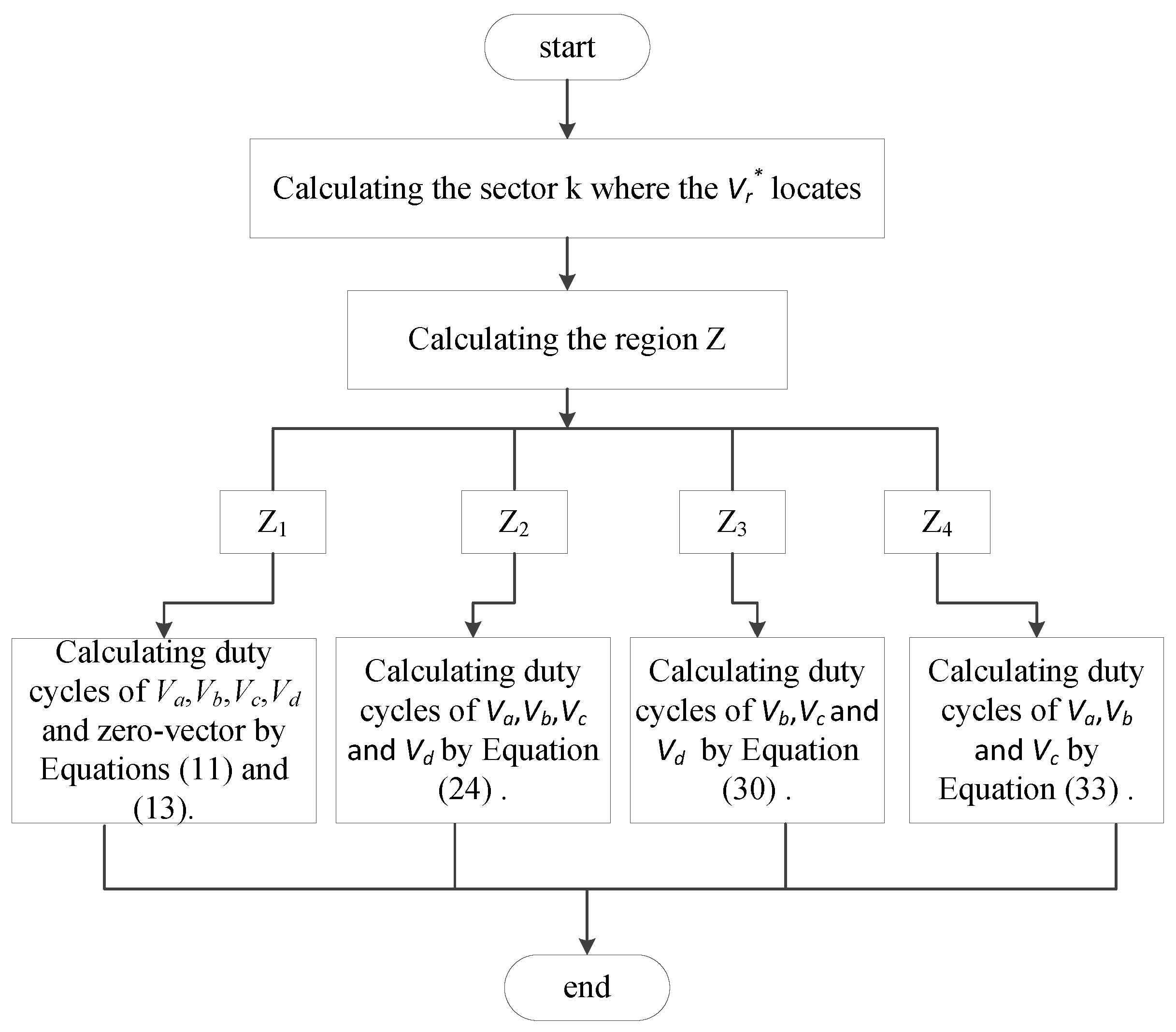
To better present this strategy, a flowchart is shown in Figure 5.

4. Simulation Results

To verify the proposed SVPWM strategy, a six-phase two-level VSI model is built on the MATLAB/Simulink platform. Simulation results of the proposed strategy are compared with that of TFOS. The simulation parameters are set as follows: output voltage frequency f = 50 Hz, carrier frequency fc = 10 kHz, and carrier period Tc = 1/fc. The dc-link voltage is set to 400 V. Harmonic voltages uz1 and uz2 are normalized by the dc-link voltage of 400 V. Simulation results are shown in Figure 6.
The Vr* crosses different regions due to different modulation index values. When the modulation index m is set to 0.585, it crosses the Z1 and Z2 regions. When the m is set to 0.605 or 0.615, it crosses the Z2, Z3 and Z4 regions. Vr* crosses the Z3 and Z4 regions when the m is set to 0.622. Harmonic voltages in the Z1 − Z2 subspace are zero in the Z1 region, whereas they are not zero in the Z2, Z3 and Z4 regions. Figure 6 shows that the voltage harmonic components of the proposed strategy are smaller than those of the TFOS.
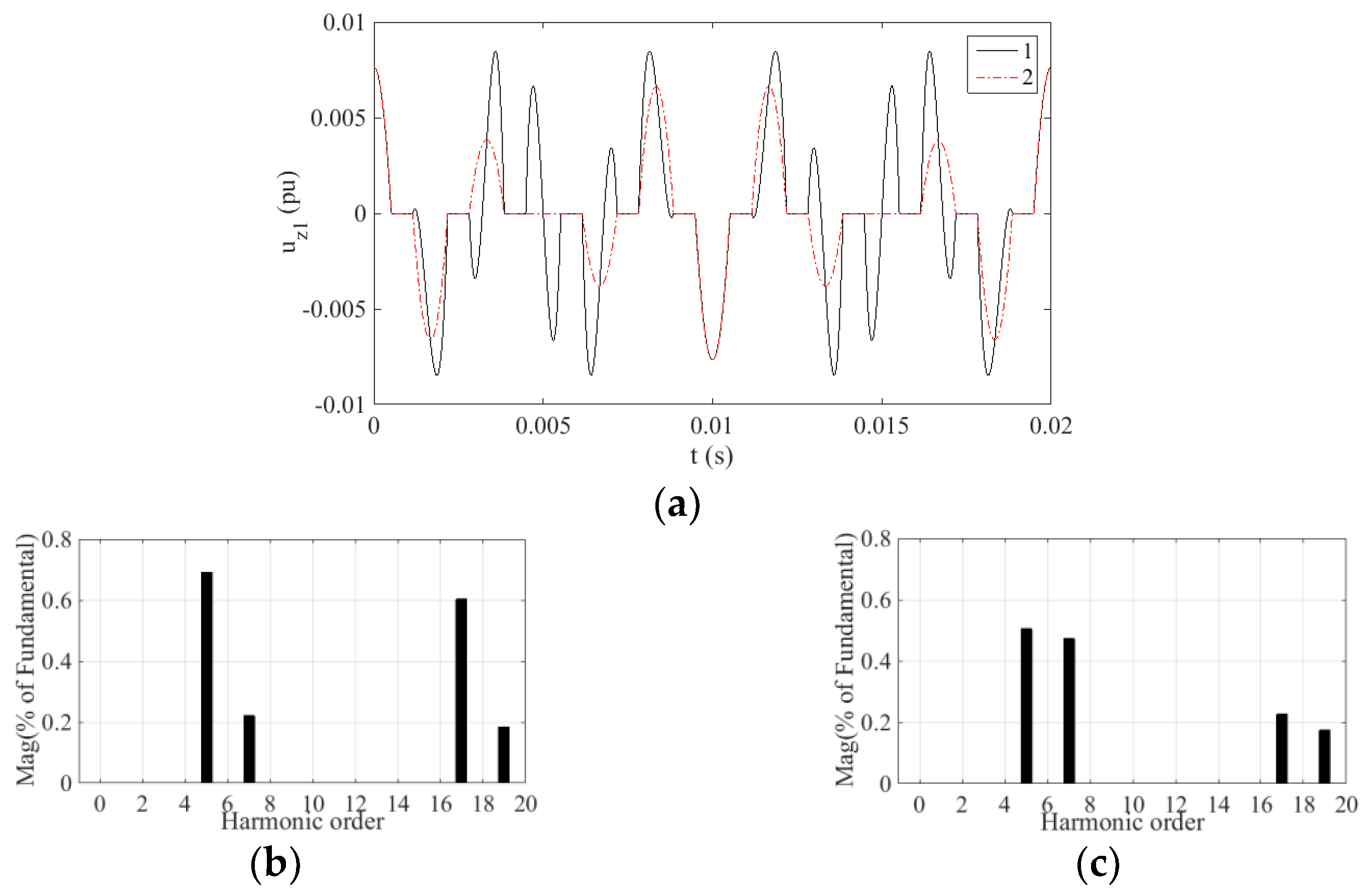
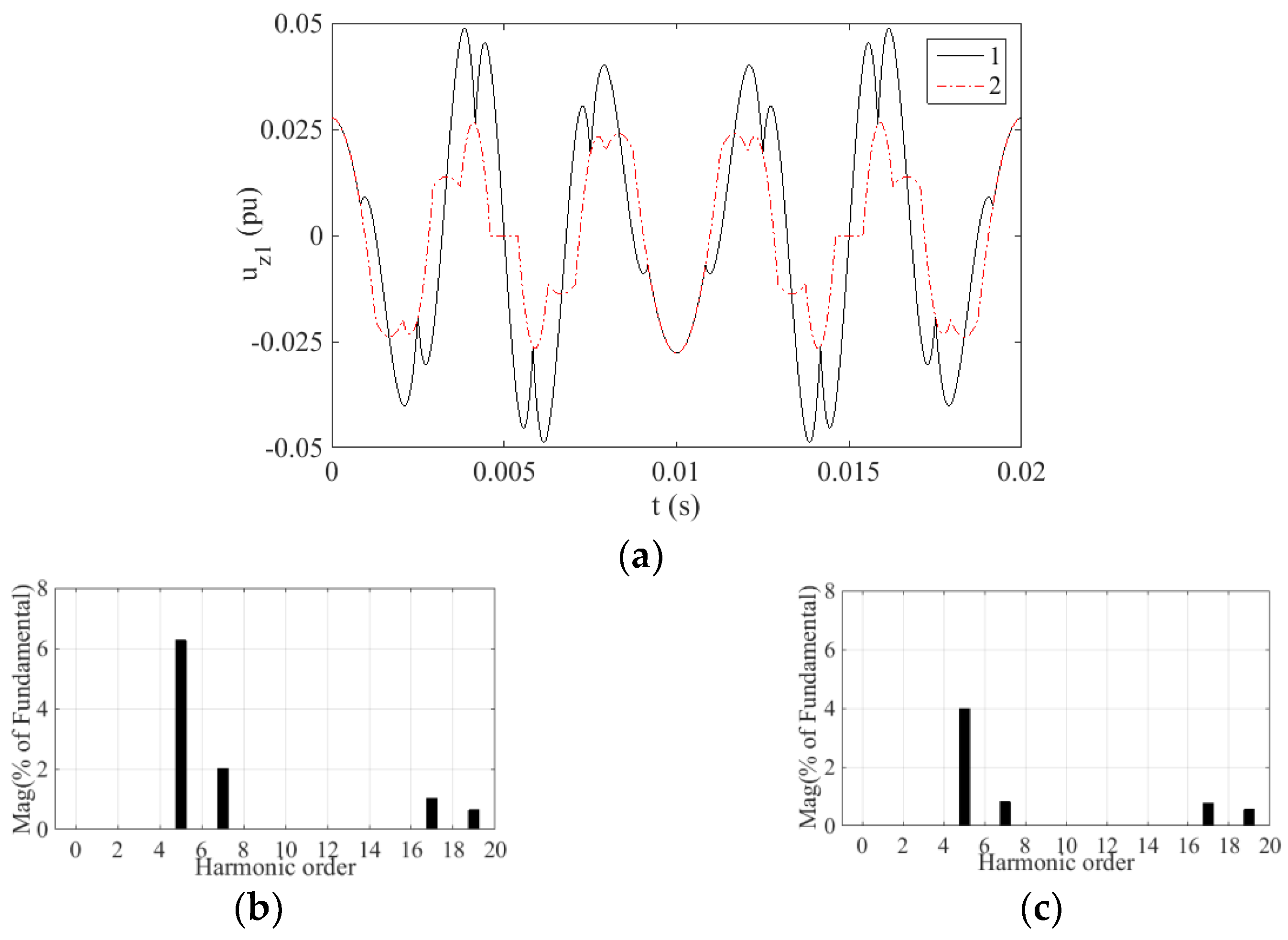
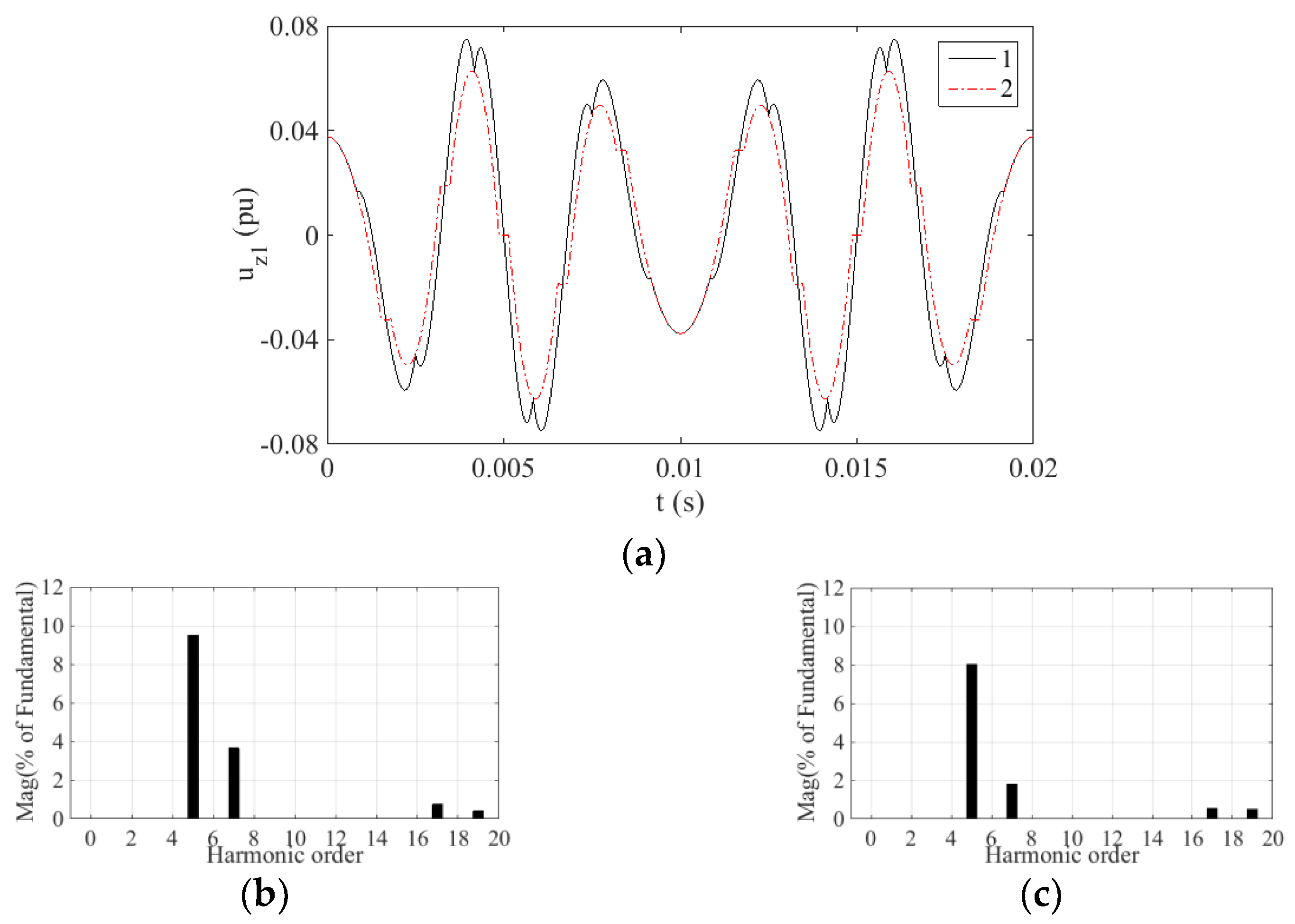
To further study the harmonic components content of voltage uz1, the uz1 waveforms of the two strategies for one fundamental period and corresponding spectrum analysis are given in Figure 7, Figure 8, Figure 9 and Figure 10. The percentage of fundamental magnitude is used as a unit in the spectrum analyses, which is consistent with the following experiment.
In the simulation, the switching frequency is 10 kHz and the harmonic analysis is in the range of up to 1 kHz. The main harmonics in the Z1 − Z2 subspace within 1 kHz are the 5th, 7th, 17th and 19th. Based on Figure 7, Figure 8, Figure 9 and Figure 10, the content of these harmonics is listed in Table 2.
As can be seen from Table 2, the content of the 5th harmonic is the largest among these four kinds of harmonics, and it is averagely reduced by 20.84% by the HSOS strategy.
According to [31], the voltage total harmonic distortion (THD) in the Z1 − Z2 subspace within 1 kHz can be calculated as:
T H D Z 1 Z 2 = U 5 2 + U 7 2 + U 17 2 + U 19 2 / U 1
where Uj is the magnitude of the j-th-order harmonic. Therefore, the THDZ1Z2 values of both strategies are obtained, as shown in Table 3.
Table 3 shows that the THDZ1Z2 of the proposed strategy is lower than that of the TFOS, especially at m = 0.605. The value of THDZ1Z2 is averagely decreased by 21.44% with these four modulation levels.
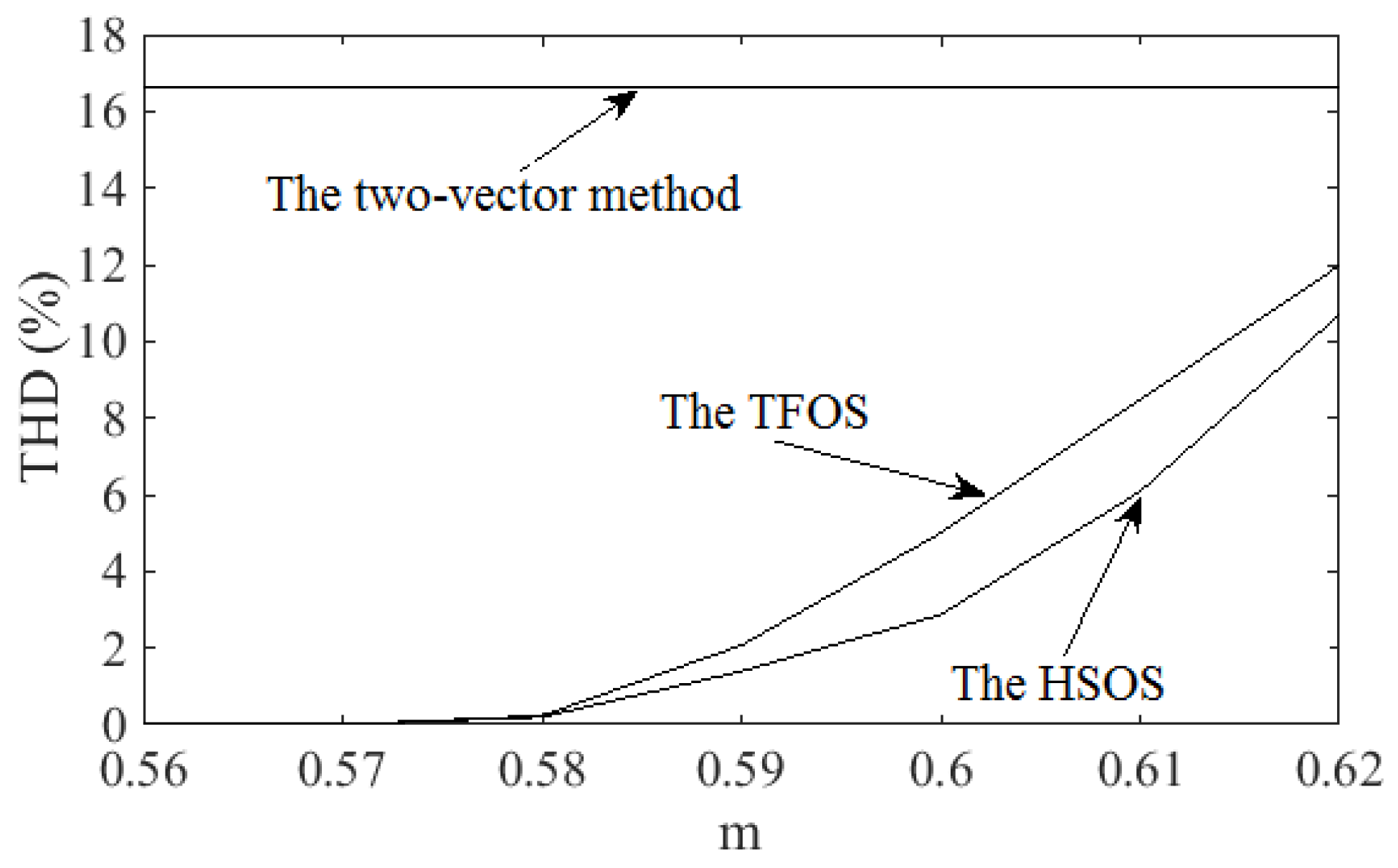
Figure 11 shows the phase voltage total harmonic distortion (THD) values of the two-vector method, the TFOS and the proposed HSOS at different values of the modulation index values. It can be seen that the THD value of the two-vector method is the highest and is maintained at approximately 16.6% [28]. When the modulation index value is greater than 0.577, the THD values of the proposed HSOS are lower than that of TFOS.

5. Experiment

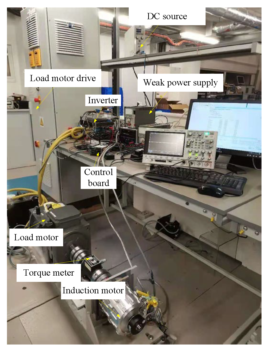
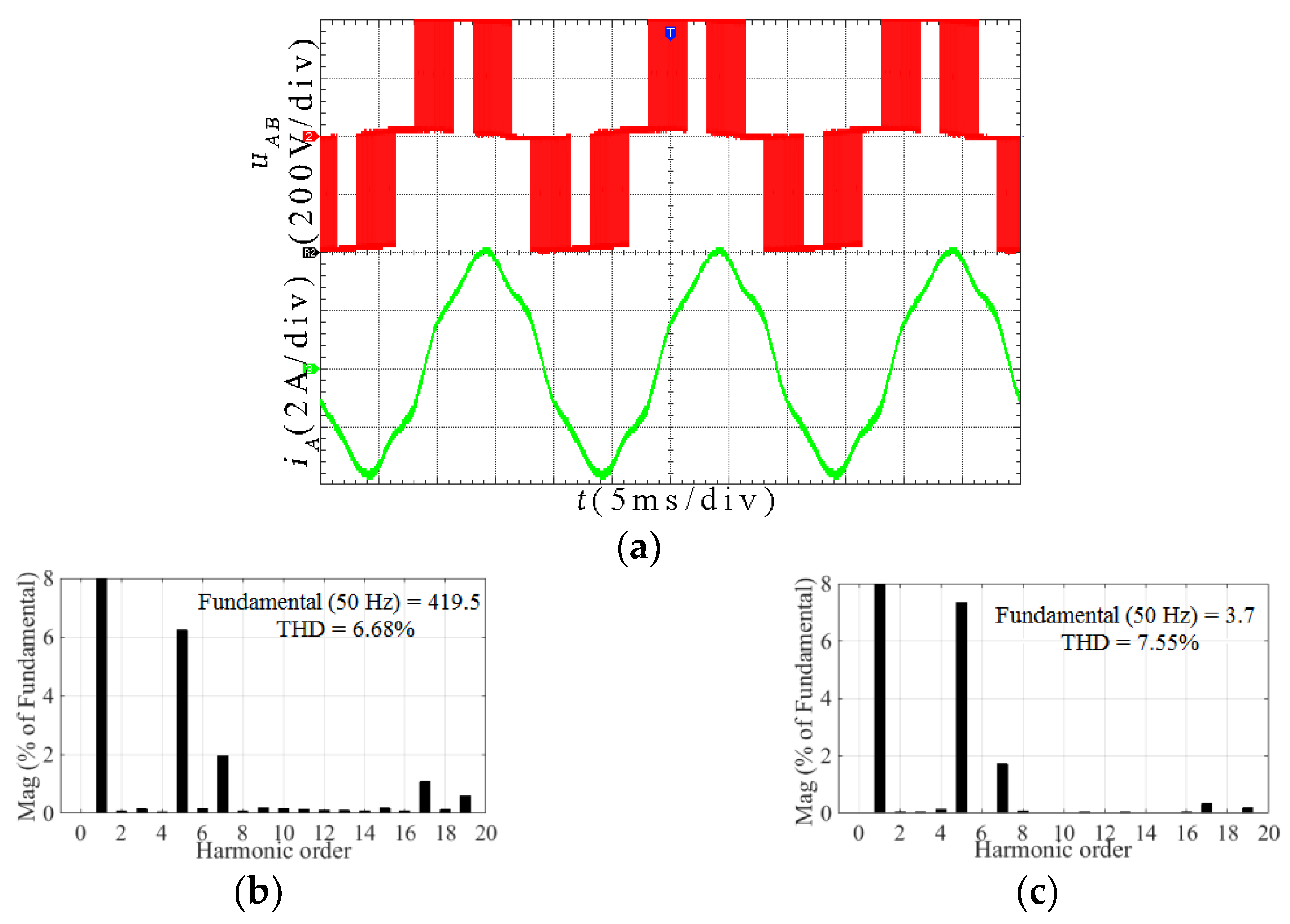
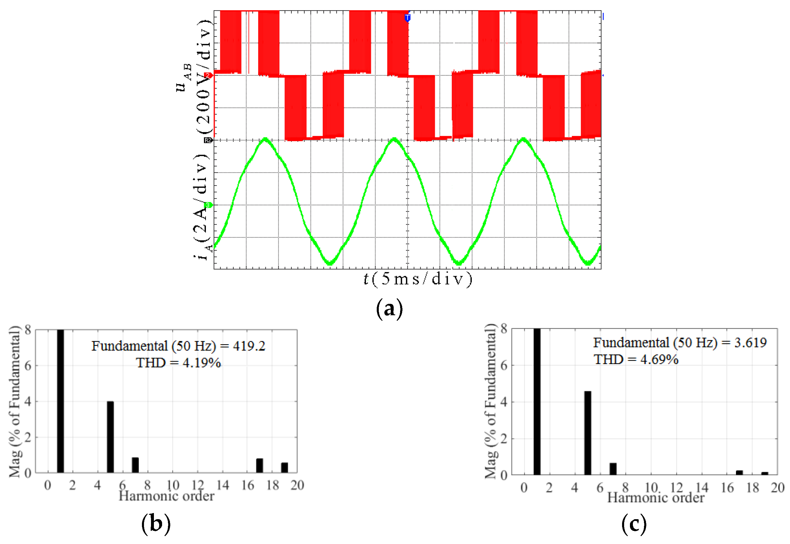
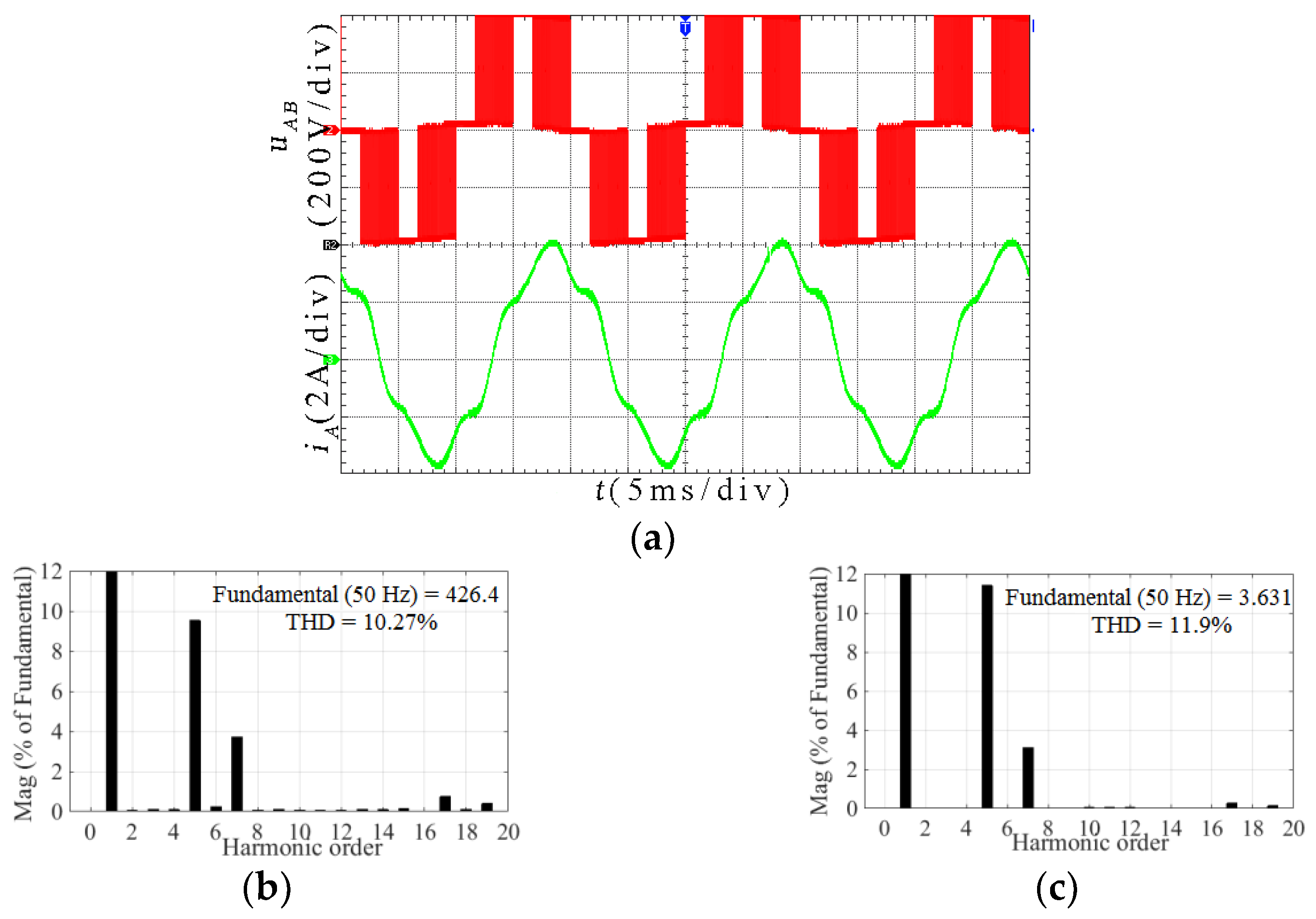
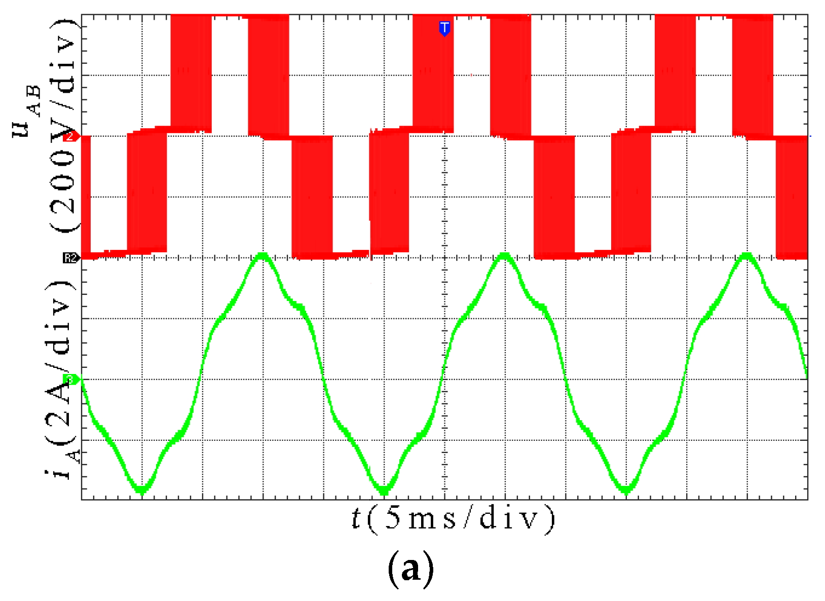
An experimental platform with the asymmetric six-phase induction motor fed by a two-level six-phase VSI is built to validate the performance of the proposed strategy, as shown in Figure 12. The platform mainly contains: a control board, a power board, a six-phase induction motor, a load motor, and a DC source. The control board is based on the Microzed evaluation board, equipped with the Xilinx Zynq System-on-Chip. It is composed of a floating-point digital signal processor (DSP) and a field programmable gate array (FPGA). The DSP is used to calculate, and the FPGA is responsible for the generation of PWM signals. The power board is implemented by the insulated gate bipolar transistor IHW30N120R2 (1200 V, 30 A, Infineon). A Switching Power Supply Weir 413D (7.5 V, 4 A) provides 5 V DC voltage for current sensors. The parameters of the six-phase induction motor are shown in Table 4. The dc-link voltage Udc = 400 V, the dead time is 1.5 μs, and the carrier frequency fc is 10 kHz. The motor starts with no-load, and a 5 N·m load torque is carried in stable motor operation. In the experiment, the modulation index m is set to 0.585, 0.605, 0.615 and 0.622, respectively. However, for the brevity of the paper, only experimental pictures of m = 0.605 and 0.615 are presented. Experimental results are shown in Figure 13, Figure 14, Figure 15 and Figure 16.
The harmonic content of line voltage and current of both strategies are listed in Table 5 and Table 6.
As can be seen from Table 5, the 5th voltage harmonic is reduced by an average of 20.97% in the HSOS strategy. According to (34), the THDZ1Z2 value of experiment voltage and current can be obtained, as shown in Table 7.
Table 2 and Table 5 show that the content of harmonic voltage is very close between simulation and experiment. Therefore, the values of THDZ1Z2 are almost the same, which can be seen from Table 3 and Table 7.
The THD value includes the harmonic distortion both in the α − β subspace and the Z1 − Z2 subspace [31]. Therefore, the THDZ1Z2 values which are shown in Table 7 are smaller than the THD values shown in Table 5 and Table 6 at the same modulation index.
As can be seen from Table 7, the THDZ1Z2 values of both voltage and current in the proposed HSOS are smaller than that of TFOS. At these four modulation levels, the voltage THDZ1Z2 value of the proposed strategy has decreased by 21.475% on average, which is close to the simulation result. Therefore, the proposed HSOS strategy can effectively suppress the harmonics in the Z1 − Z2 subspace.

6. Conclusions

In this paper, an SVPWM strategy, namely, HSOS, is proposed for the asymmetric six-phase motor fed by two-level six-phase VSI operating in the overmodulation region. In this strategy, the reference vector is synthesized and the harmonics in the Z1 − Z2 subspace are suppressed simultaneously for the overmodulation region. To minimize the harmonics in the Z1 − Z2 subspace, the optimization models consisting of an objective function and constraint conditions are built, and an external point method is adopted to solve these models.
The low-order harmonics in the Z1 − Z2 subspace mainly include the 5th, 7th, 17th and 19th, and the content of the 5th harmonic is the largest. Compared with the TFOS in the simulation and experiment, the 5th harmonic content of the proposed HSOS is reduced by 20.84% and 20.97%, and the THDZ1Z2 of these four harmonics is reduced by 21.44% and 21.475%, respectively. Therefore, the proposed HSOS can reduce the content of the 5th harmonic by about 20% and the THDZ1Z2 of the four harmonics by about 21%.

Author Contributions

Formal analysis, L.Z.; investigation, L.Z.; methodology, L.Z.; project administration, S.H.; resources, S.H.; software, L.Z.; supervision, S.H.; validation, L.Z.; visualization, L.Z.; writing—original draft, L.Z.; writing—review and editing, L.Z., J.Z. and Y.G. All authors have read and agreed to the published version of the manuscript.

Funding

This research was funded by the National Natural Science Foundation of China under grant No. 51737004, the National Key Research and Development Programs under grant No. 2016YFF0203400, the National Natural Science Foundation of China under grant No. 51777064, and the Hunan Education Department Science Research Project (21C0446).

Conflicts of Interest

The authors declare no conflict of interest.

References

  1. Sharma, S.; Aware, M.V.; Bhowate, A. Symmetrical Six-Phase Induction Motor-Based Integrated Driveline of Electric Vehicle with Predictive Control. IEEE Trans. Transp. Electrif. 2020, 6, 635–646. [Google Scholar] [CrossRef]
  2. Sun, K.; Mou, S.; Qiu, J.; Wang, T.; Gao, H. Adaptive Fuzzy Control for Nontriangular Structural Stochastic Switched Nonlinear Systems with Full State Constraints. IEEE Trans. Fuzzy Syst. 2019, 27, 1587–1601. [Google Scholar] [CrossRef]
  3. Gopakumar, K.; Ranganathan, V.; Bhat, S. Split phase induction motor operation from PWM voltage source inverter. IEEE Trans. Ind. Appl. 1993, 29, 927–932. [Google Scholar] [CrossRef] [Green Version]
  4. Acikgoz, H.; Yildiz, C.; Coteli, R.; Dandil, B. DC-link voltage control of three-phase PWM rectifier by using artificial bee colony based type-2 fuzzy neural network. Microprocess. Microsyst. 2020, 78, 103250. [Google Scholar] [CrossRef]
  5. Acikgoz, H.; Coteli, R.; Dandil, B.; Ata, F. Experimental evaluation of dynamic performance of three-phase AC–DC PWM rectifier with PD-type-2 fuzzy neural network controller. IET Power Electron. 2019, 12, 693–702. [Google Scholar] [CrossRef]
  6. Dujic, D.; Jones, M.; Levi, E. Analysis of Output Current Ripple rms in Multiphase Drives Using Space Vector Approach. IEEE Trans. Power Electron. 2009, 24, 1926–1938. [Google Scholar] [CrossRef]
  7. Huang, Y.; Walden, J.; Zhang, X.; Yan, Y.; Bai, H.; Jin, F.; Cheng, B. A Novel Zero/Reduced Common-Mode Voltage Modulation Scheme for a Dual Three-Phase Motor Drive System in Full Modulation Span. IEEE Trans. Power Electron. 2022, 37, 6765–6779. [Google Scholar] [CrossRef]
  8. Liwei, Z.; Xuhui, W.; Jun, L.; Zheng, T.Q. Math Demonstration and Practical Application of Fundamental Voltage Amplitude Linear Output Based SVPWM Overmodulation Control. In Proceedings of the IEEE Industry Applications Conference Forty-First IAS Annual Meeting, Tampa, FL, USA, 8–12 October 2006; pp. 583–587. [Google Scholar] [CrossRef]
  9. Hren, A.; Mihalič, F. An Improved SPWM-Based Control with Over-Modulation Strategy of the Third Harmonic Elimination for a Single-Phase Inverter. Energies 2018, 11, 881. [Google Scholar] [CrossRef] [Green Version]
  10. Lee, D.-C.; Lee, G.-M. A novel overmodulation technique for space-vector PWM inverters. IEEE Trans. Power Electron. 1998, 13, 1144–1151. [Google Scholar] [CrossRef]
  11. Fan, Y.; Qu, W.L.; Lu, H.F. SVPWM over-modulation algorithm based on superposition principle. J. Tsinghua Univ. 2008, 48, 461–464. [Google Scholar]
  12. Fang, H.; Feng, X.; Song, W.; Ge, X.; Ding, R. Relationship between two-level space-vector pulse-width modulation and carrier-based pulse width modulation in the over-modulation region. IET Power Electron. 2014, 7, 189–199. [Google Scholar] [CrossRef]
  13. Sola, T.E.; Chiu, H.-J.; Liu, Y.-C.; Rahman, A.N. Extending DC Bus Utilization for Induction Motors with Stator Flux Oriented Direct Torque Control. Energies 2022, 15, 374. [Google Scholar] [CrossRef]
  14. Carrasco, G.; Silva, C. Space Vector PWM Method for Five-Phase Two-Level VSI With Minimum Harmonic Injection in the Overmodulation Region. IEEE Trans. Ind. Electron. 2013, 60, 2042–2053. [Google Scholar] [CrossRef]
  15. Iqbal, A.; Moinuddin, S. Comprehensive Relationship Between Carrier-Based PWM and Space Vector PWM in a Five-Phase VSI. IEEE Trans. Power Electron. 2009, 24, 2379–2390. [Google Scholar] [CrossRef]
  16. Hu, Y.; Zhu, Z.Q.; Odavic, M. Comparison of Two-Individual Current Control and Vector Space Decomposition Control for Dual Three-Phase PMSM. IEEE Trans. Ind. Appl. 2017, 53, 4483–4492. [Google Scholar] [CrossRef]
  17. Bojoi, R.; Profumo, F.; Tenconi, A. Digital synchronous frame current regulation for dual three-phase induction motor drives. In Proceedings of the IEEE 34th Annual Conference on Power Electronics Specialist, Acapulco, Mexico, 15–19 June 2003; pp. 1475–1480. [Google Scholar] [CrossRef]
  18. Singh, G.; Nam, K.; Lim, S. A Simple Indirect Field-Oriented Control Scheme for Multiphase Induction Machine. IEEE Trans. Ind. Electron. 2005, 52, 1177–1184. [Google Scholar] [CrossRef]
  19. Gopakumar, K.; Ranganathan, V.T.; Bhat, S.R. An efficient PWM technique for split-phase induction motor operation using dual voltage source inverters. In Proceedings of the Conference Record of the 1993 IEEE Industry Applications Conference Twenty-Eighth IAS Annual Meeting, Toronto, ON, Canada, 2–8 October 1993; pp. 582–587. [Google Scholar]
  20. Zhao, Y.; Lipo, T. Space vector PWM control of dual three-phase induction machine using vector space decomposition. IEEE Trans. Ind. Appl. 1995, 31, 1100–1109. [Google Scholar] [CrossRef]
  21. Hadiouche, D.; Baghli, L.; Rezzoug, A. Space-vector PWM techniques for dual three-phase AC machine: Analysis, performance evaluation, and DSP implementation. IEEE Trans. Ind. Appl. 2006, 42, 1112–1122. [Google Scholar] [CrossRef]
  22. Prieto, J.; Levi, E.; Barrero, F.; Toral, S. Output current ripple analysis for asymmetrical six-phase drives using double ze-ro-sequence injection PWM. In Proceedings of the IECON 2011-37th Annual Conference of the IEEE Industrial Electronics Society, Melbourne, VIC, Australia, 7–10 November 2011; pp. 3692–3697. [Google Scholar]
  23. Shen, Z.; Jiang, D.; Liu, Z.; Ye, D.; Li, J. Common-Mode Voltage Elimination for Dual Two-Level Inverter-Fed Asymmetrical Six-Phase PMSM. IEEE Trans. Power Electron. 2020, 35, 3828–3840. [Google Scholar] [CrossRef]
  24. Abid, M.E.; Shaikh, M.S.; Maurya, R. Performance Investigation on SVPWM Sequences Based on Reduced Common-Mode Voltage in Dual Three-Phase Asymmetrical Machine. IEEE Trans. Power Electron. 2021, 36, 2884–2893. [Google Scholar]
  25. Suhel, S.M.; Maurya, R. Realization of 24-Sector SVPWM With New Switching Pattern for Six-Phase In-duction Motor Drive. IEEE Trans. Power Electron. 2019, 34, 5079–5092. [Google Scholar] [CrossRef]
  26. Prieto, J.; Barrero, F.; Durán, M.J.; Marín, S.T.; Perales, M.A. TFOS Procedure for n-Phase VSI With Low Harmonic Distortion in the Overmodulation Region. IEEE Trans. Ind. Electron. 2014, 61, 92–97. [Google Scholar] [CrossRef]
  27. Yazdani, D.; Khajehoddin, S.A.; Bakhshai, A.; Joos, G. Full Utilization of the Inverter in Split-Phase Drives by Means of a Dual Three-Phase Space Vector Classification Algorithm. IEEE Trans. Ind. Electron. 2009, 56, 120–129. [Google Scholar] [CrossRef]
  28. Zhou, C.; Su, J.; Yang, G. The SVPWM strategy in full modulation region for dual three-phase PMSM. Trans. China Electrotech. Soc. 2015, 30, 90–100. [Google Scholar]
  29. Yang, J.; Yang, G.; Li, T. PWM techniques for six-phase voltage-source inverters. Trans. China Electrotech. Soc. 2012, 27, 205–211. [Google Scholar]
  30. Xu, H.; Wang, S.; Wu, S.Y. Optimization Methods, Theory and Applications; Springer: Berlin/Heidelberg, Germany, 2015; pp. 185–207. [Google Scholar]
  31. Jones, M.; Dujic, D.; Levi, E.; Prieto, J.; Barrero, F. Switching Ripple Characteristics of Space Vector PWM Schemes for Five-Phase Two-Level Voltage Source Inverters—Part 2: Current Ripple. IEEE Trans. Ind. Electron. 2011, 58, 2799–2808. [Google Scholar] [CrossRef]
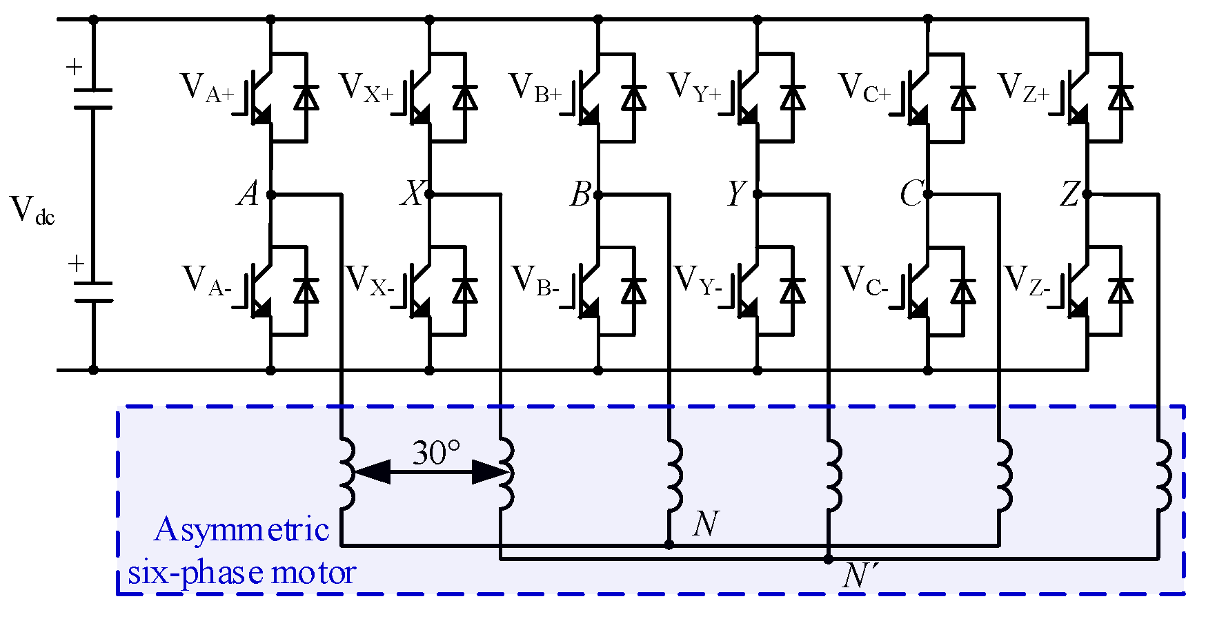
Figure 1. An asymmetric six-phase motor fed by six-phase two-level VSI.
Energies 15 07589 g001
Figure 2. Diagram of six-phase inverter voltage vectors: (a) α − β subspace and (b) Z1 − Z2 subspace.
Energies 15 07589 g002
Figure 3. Diagram of voltage vectors for the TFOS strategy: (a) α − β subspace and (b) Z1 − Z2 subspace.
Energies 15 07589 g003
Figure 4. Divided regions of the first sector.
Energies 15 07589 g004
Figure 5. Flowchart for the proposed HSOS strategy.
Energies 15 07589 g005
Figure 6. Simulated uZ1 and uZ2 trajectories results of two strategies in the Z1−Z2 subspace. Here, 1 denotes the TFOS strategy, 2 denotes the proposed HSOS strategy: (a) m = 0.585; (b) m = 0.605; (c) m = 0.615; (d) m = 0.622.
Energies 15 07589 g006
Figure 7. Simulation results uz1 of two strategies at m = 0.585. Here, 1 denotes the TFOS strategy, 2 denotes the proposed HSOS strategy: (a) uz1 waveforms of the two strategies; (b) Spectrum analysis of the TFOS; (c) Spectrum analysis of the proposed HSOS.
Energies 15 07589 g007
Figure 8. Simulation results uz1 of two strategies at m = 0.605. Here, 1 denotes the TFOS strategy, 2 denotes the proposed HSOS strategy: (a) uz1 waveforms of the two strategies; (b) Spectrum analysis of the TFOS; (c) Spectrum analysis of the proposed HSOS.
Energies 15 07589 g008
Figure 9. Simulation results uz1 of two strategies at m = 0.615. Here, 1 denotes the TFOS strategy, 2 denotes the proposed HSOS strategy: (a) uz1 waveforms of the two strategies; (b) Spectrum analysis of the TFOS; (c) Spectrum analysis of the proposed HSOS.
Energies 15 07589 g009
Figure 10. Simulation results uz1 of two strategies at m = 0.622. Here, 1 denotes the TFOS strategy, 2 denotes the proposed HSOS strategy: (a) uz1 waveforms of the two strategies; (b) Spectrum analysis of the TFOS; (c) Spectrum analysis of the proposed HSOS.
Energies 15 07589 g010
Figure 11. THD value of phase-A voltage in simulation.
Energies 15 07589 g011
Figure 12. The experiment platform.
Energies 15 07589 g012
Figure 13. Experimental results for the TFOS at m = 0.605: (a) Line voltage uAB and line current iA; (b) Spectrum analysis for uAB; (c) Spectrum analysis for iA.
Energies 15 07589 g013
Figure 14. Experimental results for the HSOS at m = 0.605: (a) Line voltage uAB and line current iA; (b) Spectrum analysis for uAB; (c) Spectrum analysis for iA.
Energies 15 07589 g014
Figure 15. Experimental results for the TFOS at m = 0.615: (a) Line voltage uAB and line current iA; (b) Spectrum analysis for uAB; (c) Spectrum analysis for iA.
Energies 15 07589 g015
Figure 16. Experimental results for the HSOS at m = 0.615. (a) Line voltage uAB and line current iA; (b) Spectrum analysis for uAB; (c) Spectrum analysis for iA.
Energies 15 07589 g016aEnergies 15 07589 g016b
Table 1. Amplitude of space vector for six-phase VSI.
Voltage VectorAmplitude
VL0.644 Udc
VM0.471 Udc
VS0.333 Udc
VE0.173 Udc
Table 2. Simulation results of the two strategies.
The TFOS Strategy
(% of Fundamental)
The HSOS Strategy (% of Fundamental)
5th7th17th19th5th7th17th19th5th Reduction (%)
m = 0.5850.690.210.60.180.510.470.220.1726.09
m = 0.6056.2210.740.80.70.535.48
m = 0.6159.53.70.80.481.70.70.615.79
m = 0.62211.74.650.550.21140.20.15.98
Table 3. Voltage THDZ1Z2 of the two strategies in simulation.
The TFOS Strategy (%)The Proposed HSOS Strategy (%)Reduction by HSOS (%)
m = 0.5850.95750.747221.96
m = 0.6056.6284.168937.1
m = 0.61510.23438.230419.58
m = 0.62212.603811.70687.12
Table 4. Parameters of the experimental six-phase motor.
rated frequency50 Hz
moment of inertia0.112 kg·m2
stator resistance1.2 Ω
rotor resistance1.4 Ω
stator leakage inductance0.0178 H
rotor leakage inductance0.0178 H
mutual inductance0.2987 H
synchronous speed1500 r/min
Table 5. Experiment voltage values of two strategies.
The TFOS Strategy (% of Fundamental)The HSOS Strategy (% of Fundamental)
THD5th7th17th19thTHD5th7th17th19th5th Reduction (%)
m = 0.5850.980.70.210.610.180.750.510.470.210.1927.14
m = 0.6056.686.1521.10.754.1940.80.750.5534.96
m = 0.61510.279.53.70.750.458.2681.750.650.615.79
m = 0.62212.6511.74.70.60.211.711140.250.155.98
Table 6. Experiment current values of two strategies.
The TFOS Strategy (% of Fundamental)The HSOS Strategy (% of Fundamental)
THD5th7th17th19thTHD5th7th17th19th
m = 0.5850.790.740.170.190.050.650.520.370.060.05
m = 0.6057.557.31.70.30.24.694.50.80.20.1
m = 0.61511.911.43.150.250.19.799.61.60.150.1
m = 0.62215.0314.44.20.20.113.7913.33.40.10.05
Table 7. Experiment voltage and current values of THDZ1Z2 of the two strategies.
Current Values (THDZ1Z2)Voltage Values (THDZ1Z2)
TFOS (%)HSOS (%)TFOS (%)HSOS (%)Reduction by HSOS (%)
m = 0.5850.78430.6430.96670.749122.51
m = 0.6057.5044.5766.60274.183936.63
m = 0.61511.83039.734110.23258.236819.52
m = 0.62215.001713.728212.624611.70837.26
Publisher’s Note: MDPI stays neutral with regard to jurisdictional claims in published maps and institutional affiliations.