Case Report

Analysis of a Costly Fiberglass-Polyester Air Filter Fire

1
Fire Disasters Research Group, Department of Safety, Chemistry and Biomedical Laboratory Sciences, Western Norway University of Applied Sciences, 5528 Haugesund, Norway
2
Q Rådgivning AS, Øvregata 126, 5527 Haugesund, Norway
3
Department of Physics and Technology, University of Bergen, 5020 Bergen, Norway
*
Author to whom correspondence should be addressed.
Energies 2022, 15(20), 7719; https://doi.org/10.3390/en15207719
Submission received: 31 August 2022 / Revised: 12 October 2022 / Accepted: 14 October 2022 / Published: 19 October 2022
(This article belongs to the Special Issue Research in Combustion and Fire Behavior of Solid Materials)

Abstract

:
In September 2020, a fire at a liquefied natural gas (LNG) plant in the Arctic areas of Norway received national attention. In an unengaged air intake, the heat exchanger designed to prevent ice damage during production mode, was supplied hot oil at 260 °C. In sunny weather, calm conditions, and 14 °C ambient temperature, overheating of the unengaged air intake filters (85% glass fiber and 15% polyester) was identified as a possible cause of ignition. Laboratory heating tests showed that the filter materials could, due to the rigid glass fibers carrying the polymers, glow like smoldering materials. Thus, self-heating as observed for cellulose-based materials was a possible ignition mechanism. Small-scale testing (10 cm × 10 cm and 8 cm stacked height) revealed that used filters with collected biomass, i.e., mainly pterygota, tended to self-heat at 20 °C lower temperatures than virgin filters. Used filter cassettes (60 cm by 60 cm and 50 cm bag depth) caused significant self-heating at 150 °C. At 160 °C, the self-heating took several hours before increased smoke production and sudden transition to flaming combustion. Since the engaged heat exchanger on a calm sunny day of ambient temperature 14 °C would result in temperatures in excess of 160 °C in an unengaged air intake, self-heating and transition to flaming combustion was identified as the most likely cause of the fire. Flames from the burning polymer filters resulted in heat exchanger collapse and subsequent hot oil release, significantly increasing the intensity and duration of the fire. Due to firewater damages, the plant was out of operation for more than 1.5 years. Better sharing of lessons learned may help prevent similar incidents in the future.

1. Introduction

Fires at industry facilities such as liquefied natural gas (LNG) plants represent a high risk to both personnel and equipment. If high-pressure natural gas, heavier hydrocarbons separated from the natural gas or the produced LNG becomes involved in the fire, the consequences may become severe. Severe fires and explosions in the oil and gas industry generally involve the loss of containment of oil or gas igniting when reaching an ignition source or hot products spontaneously igniting in contact with air, e.g., at oil refineries. The North Sea Piper Alpha platform disaster in July 1988 [1], the Texas City Refinery explosion in March 2005 [2], and the 2013 Qingdao oil pipeline leak explosion in November 2013 [3], killing, respectively, 167, 15 and 62 persons, may stand out as extreme examples of possible fire and explosion incidents associated with hydrocarbon capture, processing, and transport. Oil and gas production facilities are therefore equipped with deluge systems and fire monitors for cooling exposed piping and equipment to prevent the escalation of an initial fire. Foam may also be added to the firewater for improved active fire protection efficiency.
In such processing plants, there are, however, other products that may ignite and result in large fires, e.g., lubrication oils, turbine oils, possible hot oil for heat transfer, polymer-based air intake filters, etc.
The aim of the study is to present the investigations regarding the cause of a severe fire that took place in an air intake of an LNG plant in the Arctic region of Norway, close to the town of Hammerfest. The fire took place on 28 September 2020 and resulted in a 1.5-year shutdown of the plant, mainly due to fire water damages. Section 2 introduces the facility and the fire incident. Section 3 describes the materials and the methods used for analyzing the fire cause. Section 4 presents the results obtained, while Section 5 discusses the results and offers a comparison with similar previous incidents. The motivation for publishing the study is to present the risks identified with overheating polymer-based air filters and help preventing similar incidents in the future.

2. The Facility and the Fire Incident

2.1. The Facility

The LNG plant is located at Melkøya island in the Arctic areas of Norway, at 70.7° N, 3.8 km northwest of the Hammerfest town center, as seen in Figure 1. It employs about 500 people including external consultants, ship handling personnel, etc. It is by far the most important processing plant in the northern regions of Norway and is very important for the Hammerfest municipality.
At the plant, the well stream from the Snøhvit offshore field is separated into condensate, liquid petroleum gas (LPG), and methane, which is compressed and cooled to LNG at −163 °C. The well stream CO2 content is separated, compressed, and stored in the sediments offshore. The annual production capacity is 4.6 × 10⁶ tons LNG, 0.34 × 10⁶ tons LPG and 0.83 × 10⁶ tons of condensate [4]. It is a high-technology plant, with the lowest energy input per kg LNG produced among existing LNG plants world-wide. The production plant is self-supplied with electricity by five gas turbine generators (GTGs). It may partly operate on power from shore to reduce the release of gas turbine exhaust gases (CO2). Due to its size, and the amount of flammable gas and liquid handled, the LNG plant is one of eight Seveso directive oil and gas plants in Norway. It started production in 2007.
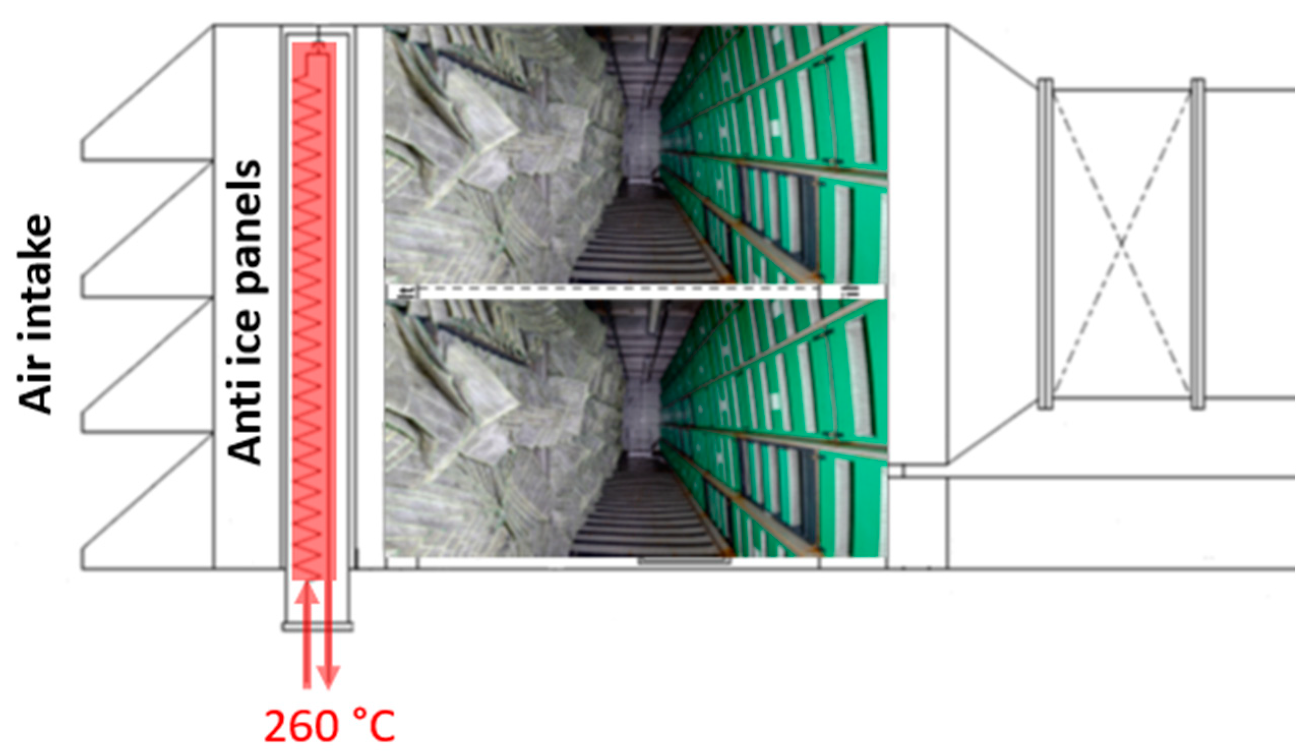
At normal speed, each GTG consumes about 100 m3 air/s. The supply air passes through an upstream filter house with coarse and fine filters to prevent turbine damage by alien objects. Acceleration of the air through the air intake and pressure reduction through the coarse and fine filters result in air expansion and adiabatic cooling [4]. For given combinations of temperatures just around and below the freezing point, and high relative humidity, ice may form in the filters. This ice may block the filters as well as represent alien objects that may damage the turbines. Thus, the supply air must be preheated to prevent ice formation. At the LNG plant, hot oil (Renolin Thermoil 30, Fuchs, Mannheim, Germany) heated to 260 °C in the turbine exhaust heat recovery unit is used as an internal energy carrier [5]. This hot oil is also used for preheating the GTG supply air a few degrees when there is risk of supply air ice formation. The heat exchanger comprises horizontal 15 mm outer diameter metal pipes carrying the hot oil. A principal sketch of the filter house is shown in Figure 2.

2.2. Sequence of Events

The LNG plant has five gas turbine generators (GTGs) supplying electricity to compressors and production processes. The GTGs were powered by production gas, and an exhaust gas heat recovery unit was used to heat hot oil for distillation column boilers, air intake heat exchangers designed to prevent ice damages during production mode, etc. In order to reduce CO2 emissions, only four GTS were normally engaged, i.e., one GTG was usually unengaged.
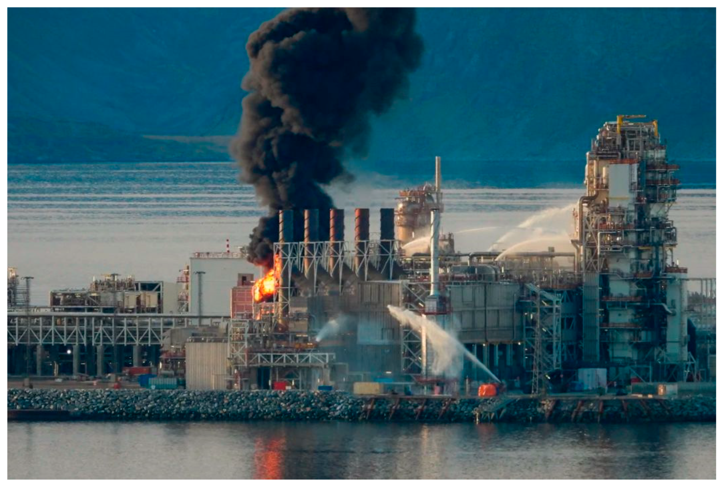
Due to a national grid anomaly, the plant tripped and had been out of operation for 10 days. During the start-up, 28 September 2020, four out of five GTGs were engaged while GTG 4 was left unengaged. To prevent overheating of the hot oil prior to engaging boilers, etc., some hot oil at 260 °C was supplied to the unengaged GTG4 air intake heat exchanger to dump excessive heat. In sunny weather, calm conditions, and 14 °C ambient temperature, overheating of the air intake filters (85% glass fiber and 15% polyester) was identified as the possible cause of a fire observed in GTG number 4, as seen in Figure 3.
This highly visible fire, in a plant with major accident potential, happened just 8 weeks after the Beirut fire and ammonium nitrate explosion disaster 4 August 2020 [6]. Thus, in the view of spectators and journalists, the fire at the LNG plant caught significant local and national attention since it was very visible from one of the largest towns in the Arctic regions of Norway.
The production area was evacuated, blowdown was initiated, and fire water monitors were engaged, as seen in Figure 3. Later, tugboats and an offshore supply vessel with firefighting (FiFi) capacity were engaged to put out the fire. It should be noted that the fire was contained to the involved air intake and did not spread to production-related hydrocarbon-containing pipes or process equipment. The fire damage, as such, was quite limited [4]. Large amounts of seawater from the fire extinguishing did, however, damage other auxiliary systems such as electrical equipment and cables [5]. Thus, the plant was shut down for a lengthy repair and maintenance period, and out of service for more than 1.5-year including delays due to the COVID-19 pandemic prior to the startup on 17 May 2022.
At first, there were no clues as to what could have ignited an unengaged air intake, i.e., at a GTG not in operation on the day of the fire. It turned out, however, that the air intake heat exchanger had been supplied with hot oil at 260 °C several hours before the fire took place. It was therefore decided to test virgin and used filters and check whether self-heating at elevated temperatures could have been the cause of the fire.

3. Materials and Methods

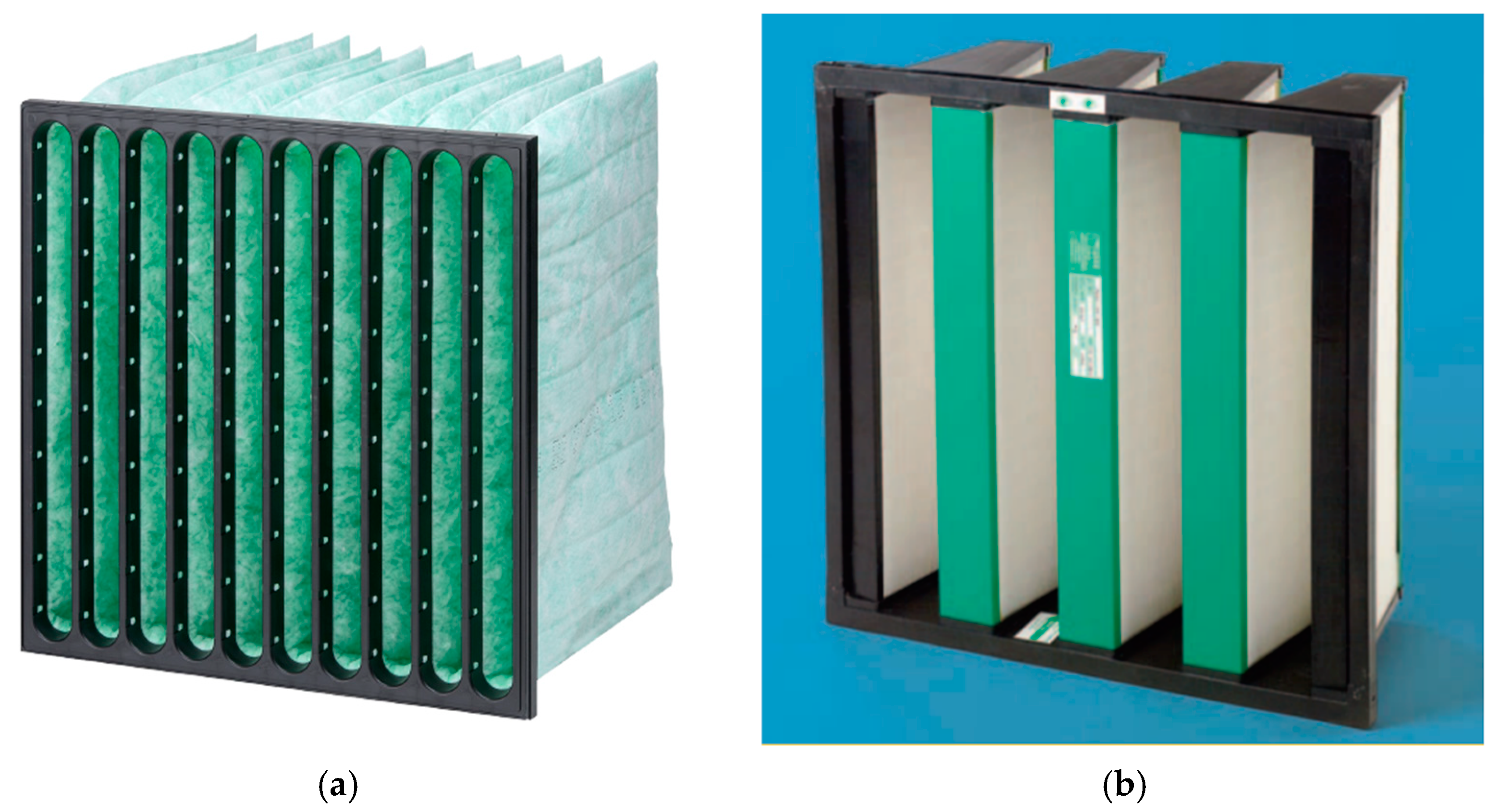
The coarse and fine filters were made of polyester (15%) and glass fiber (85%). The filters were of the types Hi-FLO XLT and Cam-GT-98klasse F9, respectively, from Camfil Inc [7]; see Figure 4. Samples were collected from virgin filters and from used filters in one of the undamaged air intake filter houses, for both small-scale and filter cassette-scale analyses.
First, small test samples were cut from virgin and used filters and ignited by a lighter for the preliminary evaluation of ignition properties, mechanisms of combustion, etc.
Then, small-scale, i.e., 10 cm × 10 cm, test samples were prepared for testing possible self-heating at elevated temperatures in a muffle furnace (Laboratory Chamber Furnace, Thermconcept GmbH, Bremen, Germany). In these self-heating tests, the test samples were stacked to 8 cm height. Thermocouples (Type K, 1.0 mm thick steel mantel) were used to record the local air exposure (muffle furnace) temperature, with thinner thermocouples (Type K, 0.5 mm mantel) used to record temperatures in the filter material. Measures were taken to minimize the tendency of the muffle furnace to exceed the set-point temperature. Thus, it was possible to detect a temperature increase in the center of the filter material if any significant self-heating was about to take place. The duration of the tests was several hours. If significant self-heating did take place, the test was aborted shortly after.
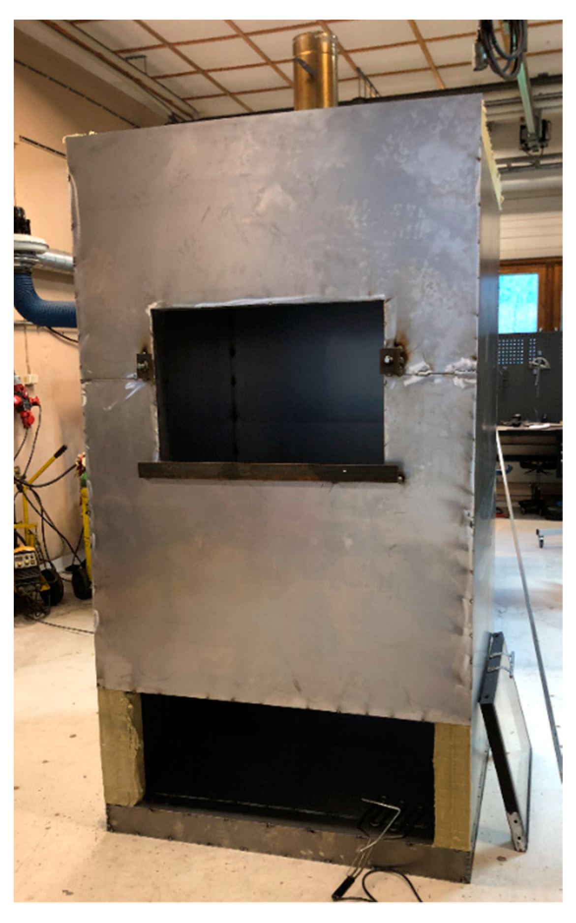
Based on the results of the small-scale testing, it was decided to also test complete filter cassettes (60 cm by 60 cm and 50 cm bag depth) at elevated temperatures, which required a much larger test volume. A 2 m3 test chamber was therefore built for this purpose, as seen in Figure 5.

4. Results

4.1. Initial Ignition Test Results

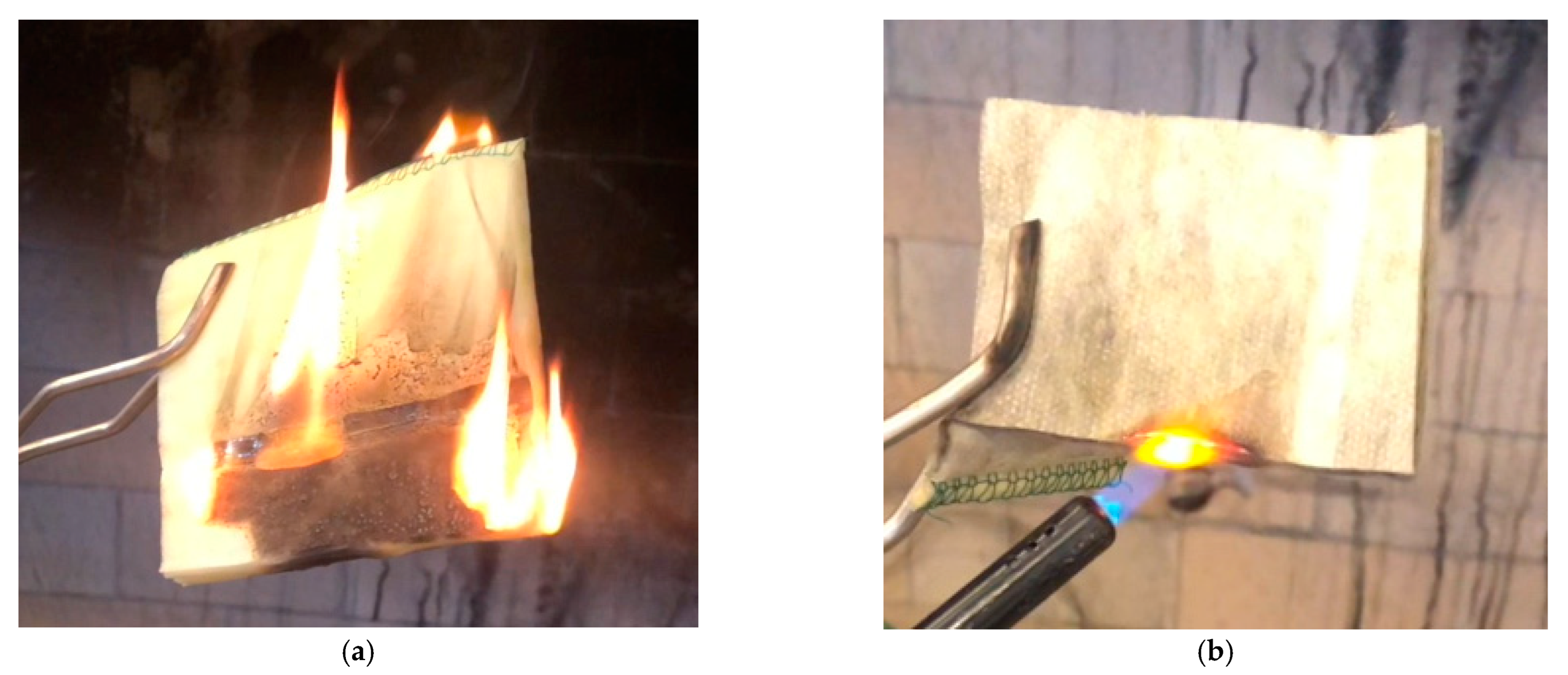
At first, there were no clues as to what could have ignited an unengaged gas turbine air intake. The air intake heat exchanger was, however, engaged, i.e., supplied with hot oil at 260 °C, for several hours before the fire took place. The upstream coarse bag filters, only 40 cm from the hot oil air supply heat exchanger, had been heat exposed due to the heated air accumulating under the air supply weather hoods. To familiarize with the combustion properties of the coarse filter material, simple ignition tests, as shown in Figure 6a,b, were undertaken.
It was quite apparent that the filter material could sustain flaming combustion, as seen in Figure 6a. When exposed to prolonged heating, as shown in Figure 6b, glowing was observed due to the hot, but still rigid, glass fiber structure. This glowing could not have been caused by the polyester, which would melt and shrink away from a heat source. Materials with this melt and shrink behavior are known to not be involved in smoldering combustion [8]. The glowing of rigid structures is one of the prerequisites associated with the self-heating and smoldering of materials such as hay or organic oil-filled rags [8]. In, e.g., cellulosic materials, the char that forms when the material is pyrolyzed represents this solid structure. Regarding the filters, there was a possibility that the glass fiber played the same role as a stiff material, thus preventing the polyester from shrinking away from the heated zone. It was therefore decided to perform small-scale self-heating tests to reveal any potential thermal runaway reactions that could eventually lead to a transition to flaming combustion.

4.2. Small Scale Self-Heating Tests

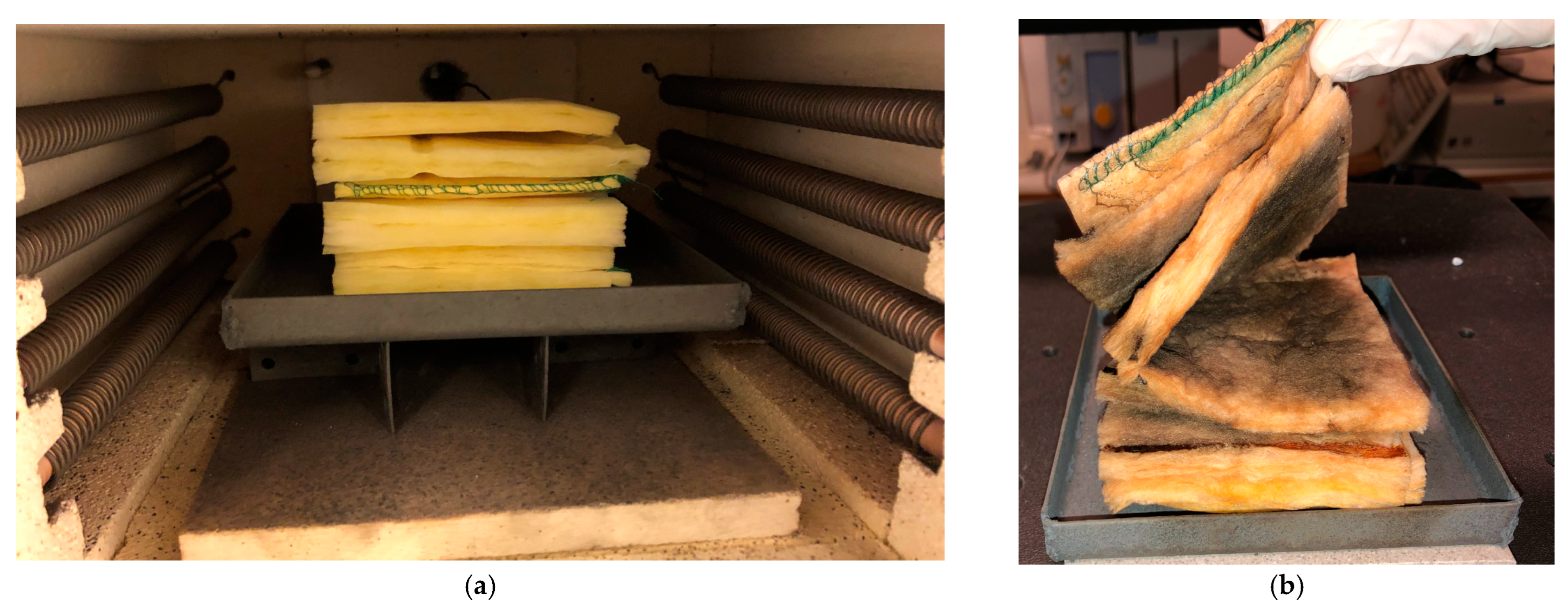
The test specimens of new and used coarse (bag) filters (10 cm by 10 cm stacked to 8 cm height) were heated in the muffle furnace, as shown in Figure 7 (virgin filters). One thermocouple (type K, 0.5 mm stainless steel mantel) was placed in the center of the test specimen filter stack, and one thermocouple was placed at the same elevation 10 mm from the edge of the stack.
The reason for placing the thermocouple 10 mm from the edge was to determine whether the self-heating was initiated at the surface of the test specimen stack due to the adjacent muffle furnace heating coils or at the center of the stack. It should also be mentioned that a fine-mesh steel screen was placed between the heating coils at each side of the muffle furnace to reduce the direct heat radiation from the heating coils to the test specimen during temperature ramp-up to the respective holding temperatures.
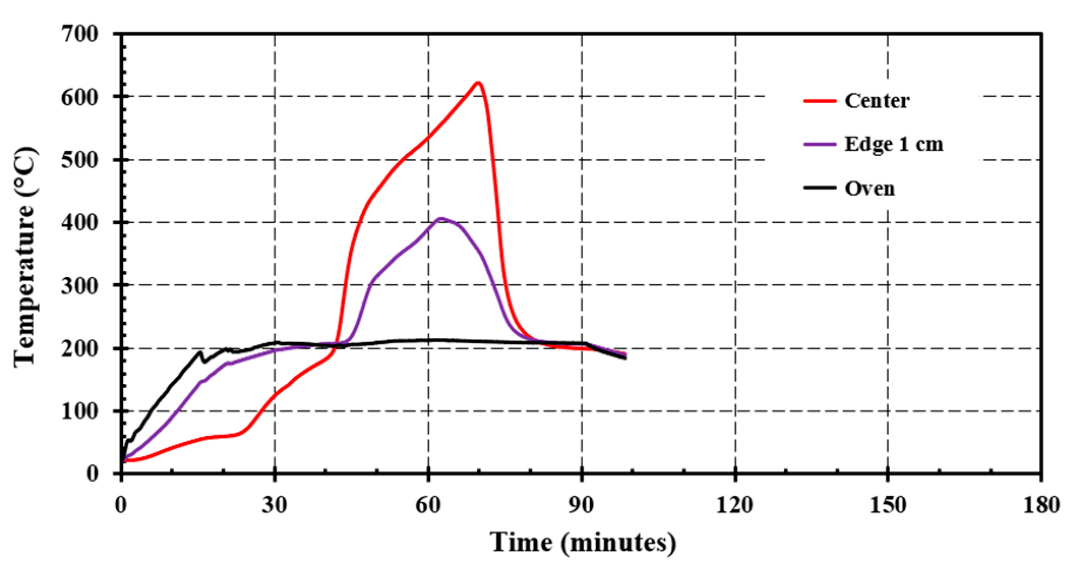
In the muffle furnace, new filters showed only a minor tendency to self-heat for set-point temperatures at, e.g., 200 °C to 205 °C, as shown in Figure 8a,b, with heating rates of 1 K/minute and 10 K/minute, respectively. It should be noted that these temperatures are well below the polyester melting point, which is typically in the range of 250 °C to 265 °C. The initiation of the self-heating process was slow, i.e., hours, at these set-point temperatures, and self-heating of the center of the test specimen stack was on the order of 5 K to 20 K, with no evidence of a runaway reaction. However, used filters at a similar temperature resulted in a spontaneous runway reaction. At a set-point temperature of 195 °C, the runaway reaction increased the temperature to above 600 °C, as seen in Figure 9b while a set-point temperature of, e.g., 180 °C, resulted in 55 °C self-heating, as seen in Figure 9a. That test was probably on the verge of a thermal runaway reaction.
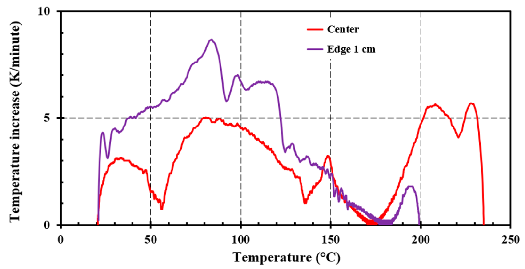
The temperature versus time development for the center thermocouple in Figure 8a,b, i.e., the new filters, was as expected by thermal conduction/thermal diffusion. For the used filters, Figure 9a,b, there was, however, a tendency for the center temperature, and partly also the temperature recorded 1 cm from the edge of the test specimen, to lag the oven temperature while below 100 °C. Plotting the time derivative of the temperature as a function of the recorded temperature, i.e., dTi/dt versus Ti, for the temperatures presented in Figure 9a, reveals a minimum at about 56 °C, as can be seen in Figure 10.
During years of operation, the used filter had collected airborne biomass such as plant leaves and pollen as well as winged creatures such as flies and mosquitos, and possibly feathers from birds, etc. Such biomass would be expected to be hygroscopic. A very likely reason for the used filters lagging some behind the oven temperature may simply be the heat required to dry any accumulated biomass. This may be a hint to why the used filters experienced a runaway reaction at lower temperatures than virgin, i.e., clean, filters.
Given sufficient oxygen supply, the volumetric heat production is generally governed by the Arrhenius equation [8]:
Q ˙ C   A × e x p ( E A R × T )
where A (1/s) is the pre-exponential parameter, E A (J/mol) is the activation energy, R (8.314 J/K∙mol) is the universal gas constant, and T (K) is the absolute temperature. The heat loss may be expressed as a linear function of the excess temperature:
Q ˙ L   A S h ( T T S )
where T S (K) is the absolute temperature of the muffle furnace, i.e., the “local ambient temperature”, A S (m2) is the test specimen area and h (W/mK) is the convective heat transfer coefficient.
If the heat production overcomes the heat losses, then a runaway reaction starts; otherwise, the heat loss controls the test specimen temperature. This is schematically presented in Figure 11 for a small and a large sample placed at holding temperatures TS1 and TS2. At set-point temperature TS1, changing the sample size from small to large reduces the runaway temperature from Ta to Tb, or, for the small test specimen, increasing the set-point temperature from TS1 and TS2 reduces the runaway temperature from Tb to Tc. The large test specimen at setpoint TS2 is on the verge of giving a runaway reaction.
If the set-point temperature had been slightly higher than TS2 in Figure 11, a runaway reaction would, at least theoretically, be expected. An experiment was therefore conducted with set-point temperature at 205 °C to further investigate this phenomenon, as seen in Figure 12. When the test specimen center temperature reached about 200 °C, an immediate runaway reaction was experienced, increasing the temperatures to above 600 °C. Whether this resulted in flaming combustion was, however, not known as the muffle oven was not equipped with a window for visual inspection during testing.
The small-scale tests revealed information about a significantly reduced temperature for a runaway combustion reaction for the used filters versus the new filters. They also revealed clues that accumulated biomass could explain the differences from the behavior of the virgin filters. Further, the results indicated that the runaway reactions were temperature and time dependent.
Based on the theoretical considerations and expressions in Equations (1) and (2), as principally analyzed in Figure 11 and practically demonstrated in Figure 12, it was clear that testing large volumes at higher temperatures would likely give a lower set-point temperature for potential self-heating runaway reactions than observed in the small-scale tests. It was therefore decided to pursue tests involving full-scale filter cassettes, i.e., about 60 cm × 60 cm × 55 cm (depth). It was also decided that these tests should allow for visual inspection since it was important to investigate whether any self-heating would result in a slow or rapid transition to flaming combustion. Any transition to flaming combustion was assumed to represent a fire strong enough to result in hot oil heat exchanger loss of containment and thus involve the hot oil in the fire, as indicated in Figure 3.

4.3. Filter Cassette Self-Heating Tests

For materials with potential for self-heating, the volume-to-surface ratio is, as indicated in Figure 12, important. It was therefore decided to test entire filter cassettes in a volume sufficiently large to contain the filter cassette including a 20 cm margin to the walls. An approximately 2 m3 thermally insulated test cabinet, where the temperature could be gradually increased and then stabilized for several hours holding time, was therefore made for the purpose. To observe the runaway reaction, and possibly identify a transition to flaming combustion, the test cabinet had to be equipped with a window, as seen in Figure 13.
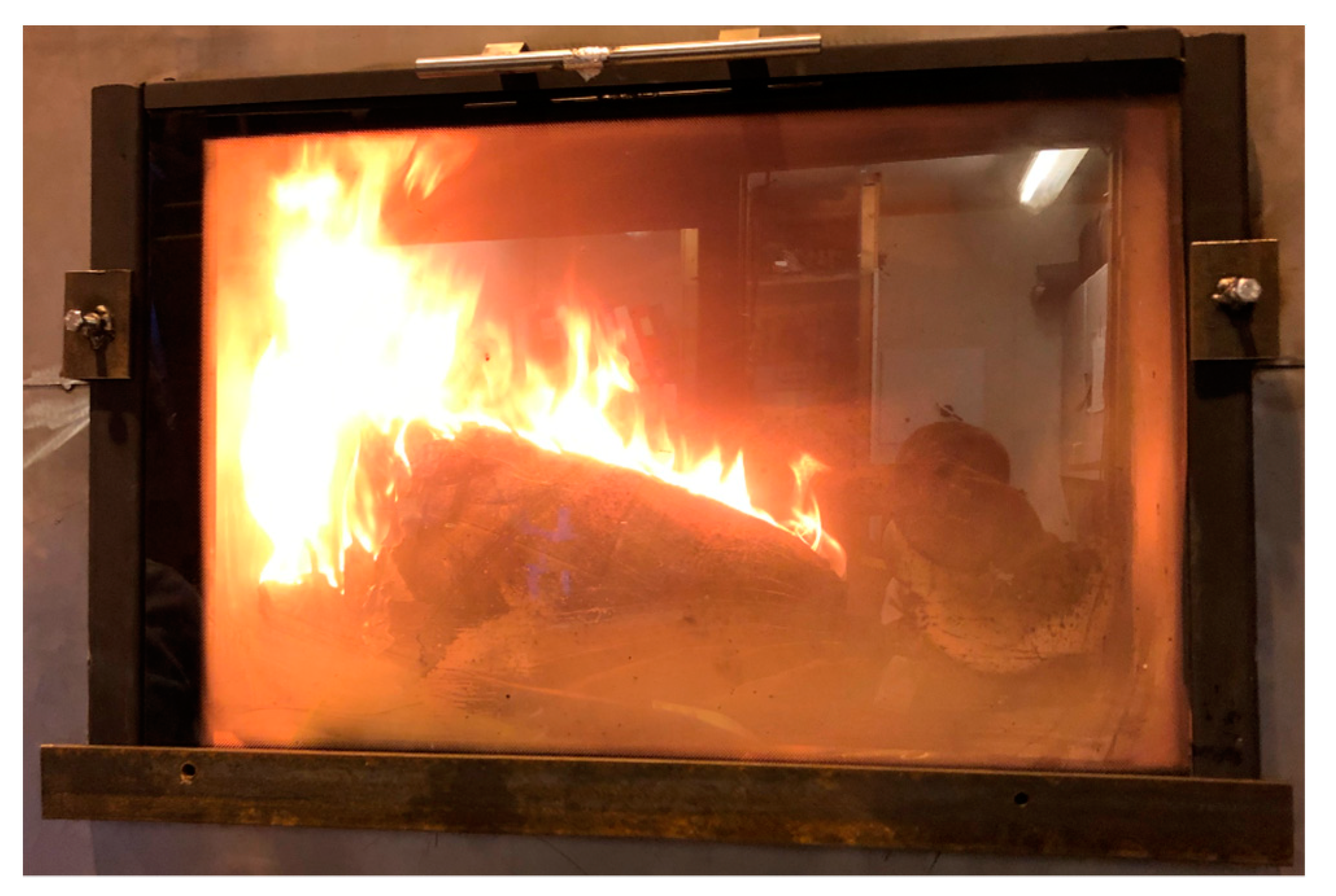
The set-point temperature of the first test was 200 °C. During the heating, the filter cassette tipped over and covered the thermocouple used for the temperature regulation. The thermocouple used to record the local ambient temperature had to be used as a control thermocouple. Therefore, no full data were monitored for this test. However, even before the temperature had stabilized, smoke was released: 2–3 s after a conspicuous increase in smoke production, two local smoke plumes at opposite sides of the filter cassette simultaneously ignited. The flaming combustion spread over the filter, which was fully engaged in flaming combustion 4–5 s after the transition to flaming combustion, as seen in Figure 13.
Both used and virgin filters were tested. As with the small-scale tests, the used filters experienced self-heating at lower temperatures than the new filters. This is evident when comparing used and new coarse filters tested at 170 °C, i.e., Figure 14a,b.
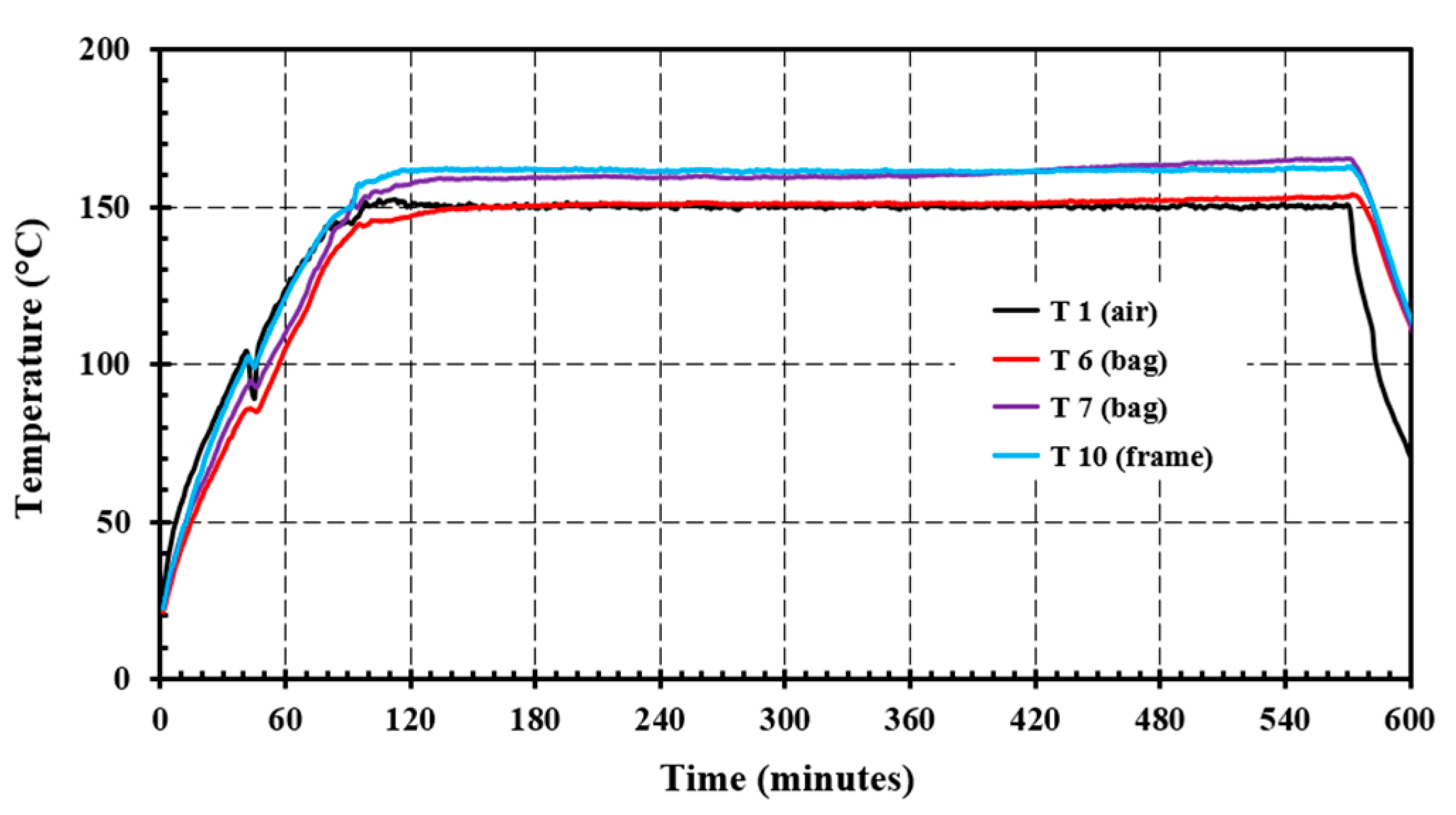
To further investigate possible self-heating of used filter cassettes at lower temperatures, a test with set-point temperature at 150 °C was undertaken; see Figure 15. Self-heating to 14–15 °C above the local ambient temperature was observed, with an increasing trend after a 7–8-h incubation period. Unfortunately, that test had to be terminated due to the late hours for a test requiring supervision.
A clue to why used coarse filters self-ignited at lower temperatures than new filters is shown in Figure 16. The used filters contained accumulated pterygota. Investigating the fraction of pterygote and other hygroscopic, e.g., plant-based materials, was not undertaken as part of the present study. Based on the time delay in the temperature increase, along with evidence as presented in Figure 16, it is suggested that accumulated biomass played a role in self-heating of the filters and that this most likely led to the fire at the LNG plant. However, catching and containing such biomass is indeed an important part of the mission of such filters.
In general, flaming combustion was observed for all coarse filter tests at temperatures at and above 160 °C. The transition from increasing smoke production to fully engaged flaming combustion was rapid, i.e., within a 2–5 s, for all the observed ignitions. Temperatures as low as 150 °C initiated significant self-heating in used coarse filters. Thus, the possibility for a runaway reaction, including transition to flaming combustion, cannot be excluded at 150 °C and was confirmed for temperatures at and above 160 °C.
CFD modelling using the Fire Dynamics Simulator (FDS) [9,10] confirmed that temperatures sufficient for initiating used filter bag self-heating was likely on a calm and sunny day with ambient temperature 14 °C. This strengthens the assumption that an unengaged air intake filter heated by the engaged heat exchanger resulted in used filter self-heating, and transition to flaming combustion. When flaming combustion took place, the heat exchanger pipes could not survive, i.e., broke and released 260 °C hot oil, changing this to an oil fire, evidenced by the thick black smoke plume as seen in, e.g., Figure 3.

5. Discussion

The present study was undertaken to investigate the possible ignition mechanism of the 28 September 2020 fire at the Hammerfest LNG plant. The involved gas turbine air intake was not engaged, while the anti-ice formation heat exchanger was supplied with hot oil at 260 °C. The question was whether the filter heating on a 14 °C, calm and sunny day could lead to further self-heating and subsequent transition to flaming combustion.
Initial ignition tests revealed that the filters showed a solid structure that glowed upon heating due to the embedded glass fiber matrices. This indicated that smoldering-like self-heating could be possible. Small scale (10 cm by 10 cm by 8 cm stack height) tests were conducted in a muffle furnace, and full-scale filter cassette tests were conducted in a heated 2 m2 cabinet with a window for observations. Temperature recordings revealed that in both small-scale tests and filter-cassette scale tests, used filters self-heated and resulted in flaming combustion at significantly lower temperature than virgin filters. The used filters had accumulated biomass. It is likely that accumulated biomass, dominated by pterygota, added combustible materials to the used filters but also likely added active surfaces for oxidation and possible self-heating to take place at a lower temperature.
The authors have not been able to identify similar incidents where self-heating has resulted in ignition of oil fires. Other filter ignitions described in the literature have, e.g., involved the self-heating of carbon filters [11] or reactive chemicals [12]. The fire investigated in the present study seems to be a particularly rare event. However, in 2015, an HVAC air intake fire occurred at the floating production storing and offloading (FPSO) ship Petrojarl Knarr (Teekay, now Altera Infrastructure Production, Inc.) [13,14]. The air intake was unengaged, while a high temperature steam heat exchanger was engaged. During testing at 180 °C [15], a filter self-ignited after a 10-h delay. Had this information been better shared, the more severe LNG plant fire involving additional hot oil could probably have been prevented.
In the filter house at the LNG plant, where the most exposed filters were likely heated to temperatures above 160 °C, one of the parameters controlling the nature of any self-heating process, i.e., heat loss to the surroundings, was compromised. When it comes to the initiation and developing of smoldering, there are two systems of primary interest, i.e., porous solid fuels, e.g., coal, polyurethane foam, tobacco and condensed-phase fuels (solid, liquid, sludge) embedded in an inert porous matrix, e.g., tar-contaminated soil, engineered mixtures of organic material and sand [16]. In the present case, the second of these two systems was the most likely, i.e., the glass fibers represented a stiff inert porous matrix for a smoldering like self-heating to take place.
In general, flaming combustion for the full-scale filters was observed for all tests at temperatures above 160 °C. The transition from increasing smoke production to fully engaged flaming combustion was rapid, i.e., within 2–5 s, for all the observed ignitions. Even at 150 °C, 15 °C self-heating was observed. This indicates that a runaway reaction and transition to flaming combustion cannot be excluded at temperatures as low as 150 °C.
Transition from smoldering to flaming combustion has been studied extensively in recent years for, e.g., polyurethane foams [17,18], cotton [19], pine needles and wood powder [20], peat [21], and coal waste dumps [22], and since smoldering results in many deaths worldwide, much work has addressed preventing materials for initiating smoldering combustion, e.g., [23]. When it comes to the combination of glass fibers and polymers, several fire-related studies have focused on flaming combustion of glass fiber-reinforced epoxy resins, e.g., [24,25,26]. These materials do not, however, behave like the porous filter bags involved in the fire at the LNG plant when heated. Oxidation reactions and the spontaneous ignition of glass wool impregnated with linseed oil was previously studied [27]. This is, however, also quite different from the glass fiber polyester filters tested in the present case study. It has not been possible to find other studies regarding porous glass fiber matrixes carrying polymers that display self-heating or smoldering-like combustion at elevated temperatures.
For the transition to flaming combustion observed in the full-scale filter tests in the present study, it was not possible to determine the transition mechanisms. Several studies [17,18,19,20] consider the inclination and porosity of tested materials to be important for transition from smoldering to flaming combustion. In the present study, the filter cassettes allowed for inclined and vertical surfaces between individual filter bags where the suddenly fast-developing smoke plumes could be ignited. To study this in more depth would require a dedicated experimental set-up, which was not within the scope of the present study.
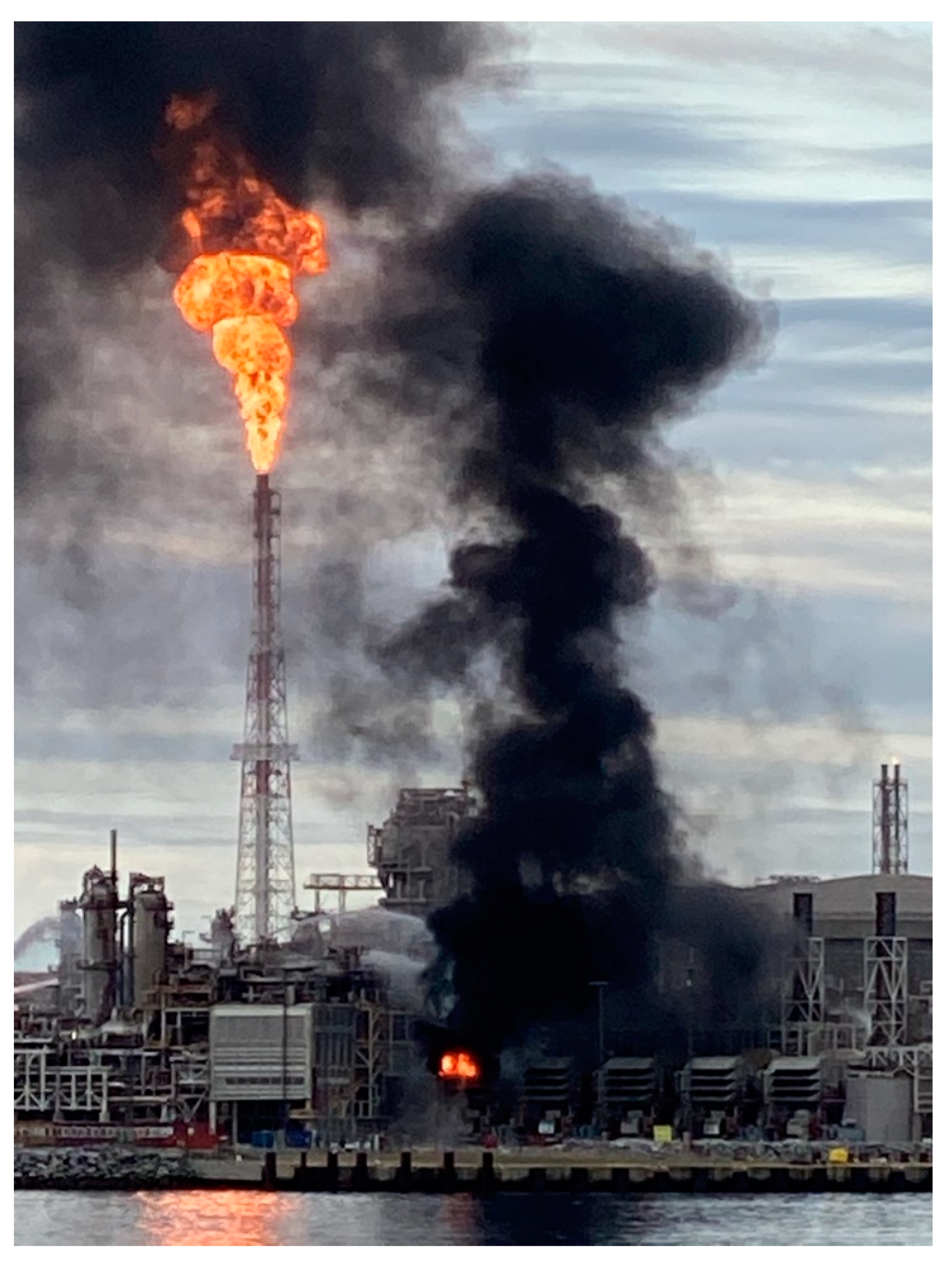
Since no other ignition sources could be identified, and a similar filter fire took place at Petrojarl Knarr FPSO five years earlier [13,14], it was most likely that the engaged heat exchanger resulted in temperatures sufficient for further delayed self-heating of the filters at the gas turbine generator air intake. After hours of incubation, this likely resulted in a rapid transition to flaming combustion involving all filters available for combustion. When exposed to flames, the heat exchanger pipes disintegrated and released hot oil, which turned the fire into an oil fire with a conspicuous black smoke plume visible from Hammerfest and vicinity. A photo taken from the public transport fast-ferry catamaran Sørøysundekspressen, Figure 17, shows the filter house fire and the massive depressurization flaring of the plant to reduce the risk of fire spread to hydrocarbon containing equipment.
Self-heating has previously resulted in many fires in Norwegian barns when too humid grass was stored in large volumes. Self-heating has also resulted in accidents in the oil and gas industry. In 2007, a violent explosion of the content of a large atmospheric storage tank in a purification plant for coker gasoline took place. In that case, the ignition was most likely due to a hot surface resulting from the adsorption of volatile organic compounds on activated filter carbon, causing self-heating and subsequent glowing carbon bed combustion and gas phase ignition [11]. That incident injured two workers. It appears that self-heating as a possible ignition source has not received sufficient focus in Norwegian oil and gas industries.
There has been much focus on preventing and mitigating fires in hydrocarbon-carrying pipes and equipment, and research on, e.g., active [28,29] and passive [30,31] fire protection of these systems. However, in recent years, several incidents in Norway have struck the utility systems, e.g., a high-voltage room quasi-smoke gas explosion [32] and a major fire in a steam-powered turbine generator [33] as well as the fire analyzed in the present study [4,5]. It may be concluded that the utility systems need more risk attention.
Simple measures could often significantly reduce the consequences of the developing incidents. A temperature alarm being triggered when exceeding the 70 °C design temperature [7] and/or better sharing of knowledge of an air intake filter fire, like the one at, e.g., Petrojarl Knarr FPSO [13,14] in the North Sea, could have prevented the fire at Hammerfest LNG. Sharing incident information may help prevent similar future air intake fires by, e.g., understanding possible self-heating mechanisms and the influence of accumulated biomass, installing warning systems for excessive filter house temperature, improving operation procedures, etc. Improved emergency training in cooperation with the fire brigades [34,35] could also have minimized the consequences of the fire. For further underlying causes of the LNG plant fire ignition mechanism analyzed in the present study, and evaluations regarding the emergency operation, interested readers are referred to the openly shared company investigation report [4] and the PSA report [5].
Better sharing of lessons learned may help preventing future incidents. Sharing the findings from the present study may help industries using air intake filters with ice prevention heat exchangers to become more aware of the possible associated fire risk, allowing for systems warning about possible elevated temperatures, early phase self-heating and/or measures to reduce the impact of possible fires to possibly be installed to manage potential air intake fire risks.

6. Conclusions

The present study shows that glass fibers may represent the rigid structure necessary for glass fiber–polyester filters to initiate self-heating at elevated temperatures, i.e., like cellulose-based materials. It was also shown that used filters with accumulated biomass, i.e., mainly pterygota, tended to self-heat at 20 °C lower temperatures than virgin filters. At 160 °C, several-hours-delayed self-heating suddenly resulted in increased smoke production and a rapid transition to flaming combustion. These findings may explain the ignition mechanism of a severe fire at an LNG facility in Norway September 2020. In a calm sunny day of ambient temperature 14 °C, an unengaged air intake was supplied hot oil at 260 °C to its heat exchanger, heating the air intake filters to above 160 °C. Several hours later, a sudden transition to flaming combustion occurred. The burning filters damaged the heat exchanger piping, fueling the fire with hot oil and thus, significantly increasing the fire severity. Due to firewater damages, the plant was out of operation for more than 1.5 years. Better sharing of lessons learned may help prevent similar incidents in the future.

Author Contributions

Conceptualization, T.L.; methodology, T.L. and A.G.; measurements, A.G.; validation, T.L. and A.G.; formal analysis, T.L.; investigation, T.L.; resources, T.L.; data curation, T.L.; writing—original draft preparation, T.L.; writing—review and editing, T.L. and A.G.; visualization, T.L. and A.G.; supervision, T.L.; project administration, T.L.; funding acquisition, T.L. All authors have read and agreed to the published version of the manuscript.

Funding

This fire testing was funded by Equinor. The APC was funded by the Western Norway University of Applied Sciences.

Data Availability Statement

Not applicable.

Acknowledgments

The 2 m2 test compartment constructed by RISE Fire Research, Trondheim, Norway, who also performed the filter scale measurements, is highly appreciated. The anonymous reviewers’ suggestions for improving the paper are highly appreciated.

Conflicts of Interest

The authors declare no conflict of interest. The funders had no role in the design of the study; in the collection, analyses, or interpretation of data; in the writing of the manuscript; or in the decision to publish the results.

References

  1. Drysdale, D.D.; Sylvester-Evans, R. The explosion and fire on the Piper Alpha platform, 6 July 1988. A. case study. Phil. Trans. R. Soc. A Math. Phys. Eng. Sci. 1998, 356, 2929–2951. [Google Scholar] [CrossRef]
  2. Holmstrom, D.; Altamirano, F.; Banks, J.; Joseph, G.; Kaszniak, M.; Mackenzie, C.; Shroff, R.; Cohen, H.; Wallace, S. CSB investigation of the explosions and fire at the BP Texas City refinery on March 23, 2005. Proc. Safety Progr. 2006, 25, 345–349. [Google Scholar] [CrossRef]
  3. Zhu, Y.; Qian, X.M.; Liu, Z.Y.; Huang, P.; Yuan, M.Q. Analysis and assessment of the Qingdao crude oil vapor explosion accident: Lessons learnt. J. Loss Prev. Proc. Ind. 2015, 33, 289–303. [Google Scholar] [CrossRef]
  4. Bakka, M.S.; Eriksen, B.; Johansen, O.J.; Oltedal, H.-L.-; Nissestad, O.A.; Log, T. Brann i luftinntak på gassturbin GTG4, Hammerfest LNG 28.09.2020 (En. Fire in air intake at gas turbine GTG4, Hammerfest LNG 28.09.2020); Report no. A MMP L2 2020-18; Equinor: Forus, Norway, 2021. [Google Scholar]
  5. Hallan, B.; Rundell, L.R.; Thorsen, A.J.; Steinmakk, A.-H.; Sundby, T. Rapport etter gransking av brann i luftinntak til GTG4 på Hammerfest LNG, Melkøya (En. Investigation report after fire in air intake for GTG4 at Hammerfest LNG, Melkøya); Norwegian Petroleum Safety Authority investigation report, activity 001901043; Equinor: Stavanger, Norway, 2021. (In Norwegian) [Google Scholar]
  6. Agapiou, A. Damage Proxy Map of the Beirut Explosion on 4th of August 2020 as Observed from the Copernicus Sensors. Sensors 2020, 20, 6382. [Google Scholar] [CrossRef] [PubMed]
  7. Camfil. Hi-Flo XLT filterpåse. Byggvarudeklaration, Camfil Sweden, Stockholm, Sweden. 2015. Available online: www.camfil.com/damdocuments/46633/1217698/ebvd-hi-flo-xlt.pdf (accessed on 1 December 2020).
  8. Drysdale, D.D. An Introduction to Fire Dynamics, 2nd ed.; John Wiley: New York, NY, USA, 1999; ISBN 0-471-97291-6. [Google Scholar]
  9. McGrattan, K.; Hostikka, S.; McDermott, R.; Floyd, J.; Weinschenk, C.; Overholt, K. Fire dynamics simulator user’s guide. NIST Special Publ. 2013, 1019, 339. [Google Scholar] [CrossRef]
  10. McGrattan, K.; Hostikka, S.; McDermott, R.; Floyd, J.; Weinschenk, C.; Overholt, K. Fire dynamics simulator technical reference guide volume 1: Mathematical model. NIST Special Publ. 2013, 1018, 175. [Google Scholar] [CrossRef]
  11. Skjold, T.; van Wingerden, K. Investigation of an explosion in a gasoline purification plant. Proc. Safety Progr. 2013, 32, 268–276. [Google Scholar] [CrossRef]
  12. McAllister, P.M.; Dyche, J.L.; Graves, R.C. Investigation and actions after an internal air compressor filter fire. Proc. Safety Progr. 2013, 32, 96–101. [Google Scholar] [CrossRef]
  13. Larsen, A.; Sande, E.; Glette, S.H.; Jensen, J.E. Report after Fire in Ventilation Hood at Petrojarl Knarr 24.3.2015; Investigation report, 411003011; The Petroleum Safety Authority: Stavanger, Norway, 2015. (In Norwegian) [Google Scholar]
  14. Government of Norway. Investigation—Fire in HVAC room onboard Petrojarl Knarr, Teekay Petrojarl TKPJ-01-S-97-RA-00001-001, 2015; Government of Norway: Oslo, Norway, 2015.
  15. Stølen, R. Fire in HVAC Room on Board Petrojarl Knarr; F15 20141-2:1; SP Fire Research: Trondheim, Norway, 2015. [Google Scholar]
  16. Torero, J.L.; Gerhard, J.I.; Martins, M.F.; Zanoni, M.A.B.; Rashwan, T.L.; Brown, J.K. Processes defining smouldering combustion: Integrated review and synthesis. Progr. Energy Combust. Sci. 2020, 81, 100869. [Google Scholar] [CrossRef]
  17. Wang, Z.; Liu, N.; Yuan, H.; Chen, H.; Xie, X.; Zhang, L.; Rein, G. Smouldering and its transition to flaming combustion of polyurethane foam: An experimental study. Fuel 2022, 309, 122249. [Google Scholar] [CrossRef]
  18. Morgan, A.B.; Knapp, G.; Stoliarov, S.I.; Levchik, S.V. Studying smoldering to flaming transition in polyurethane furniture subassemblies: Effects of fabrics, flame retardants, and material type. Fire Mater. 2021, 45, 56–67. [Google Scholar] [CrossRef]
  19. Hagen, B.C.; Meyer, A.K. From smoldering to flaming fire: Different modes of transition. Fire Safety J. 2021, 121, 103292. [Google Scholar] [CrossRef]
  20. Wang, Q.; Liu, K.; Wang, S. Effect of porosity on ignition and burning behavior of cellulose materials. Fuel 2022, 322, 124158. [Google Scholar] [CrossRef]
  21. Graham, L.L.B.; Applegate, G.B.; Thomas, A.; Ryan, K.C.; Saharjo, B.H.; Cochrane, M.A. A Field Study of Tropical Peat Fire Behaviour and Associated Carbon Emissions. Fire 2022, 5, 62. [Google Scholar] [CrossRef]
  22. Gogola, K.; Rogala, T.; Magdziarczyk, M.; Smoliński, A. The Mechanisms of Endogenous Fires Occurring in Extractive Waste Dumping Facilities. Sustainability 2020, 12, 2856. [Google Scholar] [CrossRef] [Green Version]
  23. Xu, K.; Tian, X.; Cao, Y.; He, Y.; Xia, Y.; Quan, F. Suppression of Smoldering of Calcium Alginate Flame-Retardant Paper by Flame-Retardant Polyamide-66. Polymers 2021, 13, 430. [Google Scholar] [CrossRef]
  24. Korobeinichev, O.; Shaklein, A.; Trubachev, S.; Karpov, A.; Paletsky, A.; Chernov, A.; Sosnin, E.; Shmakov, A. The Influence of Flame Retardants on Combustion of Glass Fiber-Reinforced Epoxy Resin. Polymers 2022, 14, 3379. [Google Scholar] [CrossRef] [PubMed]
  25. Shi, X.; Luo, S.; Du, X.; Li, Q.; Cheng, S. Improvement the Flame Retardancy and Thermal Conductivity of Epoxy Composites via Melamine Polyphosphate-Modified Carbon Nanotubes. Polymers 2022, 14, 3091. [Google Scholar] [CrossRef]
  26. Korobeinichev, O.; Karpov, A.; Shaklein, A.; Paletsky, A.; Chernov, A.; Trubachev, S.; Glaznev, R.; Shmakov, A.; Barbot’ko, S. Experimental and Numerical Study of Downward Flame Spread over Glass-Fiber-Reinforced Epoxy Resin. Polymers 2022, 14, 911. [Google Scholar] [CrossRef]
  27. Juita; Dlugogorski, B.Z.; Kennedy, E.M.; Mackie, J.C. Oxidation reactions and spontaneous ignition of linseed oil. Proc. Comb. Inst. 2011, 33, 2625–2632. [Google Scholar] [CrossRef]
  28. Bjørge, J.S.; Metallinou, M.-M.; Log, T.; Frette, Ø. Method for Measuring Cooling Efficiency of Water Droplets Impinging onto Hot Metal Discs. Appl. Sci. 2018, 8, 953. [Google Scholar] [CrossRef] [Green Version]
  29. Bjørge, J.S.; Bjørkheim, S.A.; Metallinou, M.M.; Log, T.; Frette, Ø. Influence of acetone and sodium chloride additives on cooling efficiency of water droplets impinging onto hot metal surfaces. Energies 2019, 12, 2358. [Google Scholar] [CrossRef] [Green Version]
  30. Bjørge, J.S.; Metallinou, M.M.; Kraaijeveld, A.; Log, T. Small Scale Hydrocarbon Fire Test Concept. Technologies 2017, 5, 72. [Google Scholar] [CrossRef] [Green Version]
  31. Bjørge, J.S.; Gunnarshaug, A.; Log, T.; Metallinou, M.-M. Study of Industrial Grade Thermal Insulation as Passive Fire Protection up to 1200 °C. Safety 2018, 4, 41. [Google Scholar] [CrossRef] [Green Version]
  32. Bakka, M.S.; Handal, E.K.; Log, T. Analysis of a High-Voltage Room Quasi-Smoke Gas Explosion. Energies 2020, 13, 601. [Google Scholar] [CrossRef] [Green Version]
  33. Handal, E.; Sandvik, O.I.; de Jong, H.; Bondevik, T.B.; Ovesen, R.V. Fire in Compressor House; Report no. A MMP L1 2020–2023; Equinor: Forus, Norway, 2021. [Google Scholar]
  34. Metallinou, M.M. Single-and double-loop organizational learning through a series of pipeline emergency exercises. J. Contingencies Crisis Manag. 2017, 26, 530–543. [Google Scholar] [CrossRef]
  35. Metallinou, M.M. Liquefied Natural Gas as a New Hazard; Learning Processes in Norwegian Fire Brigades. Safety 2019, 5, 11. [Google Scholar] [CrossRef]
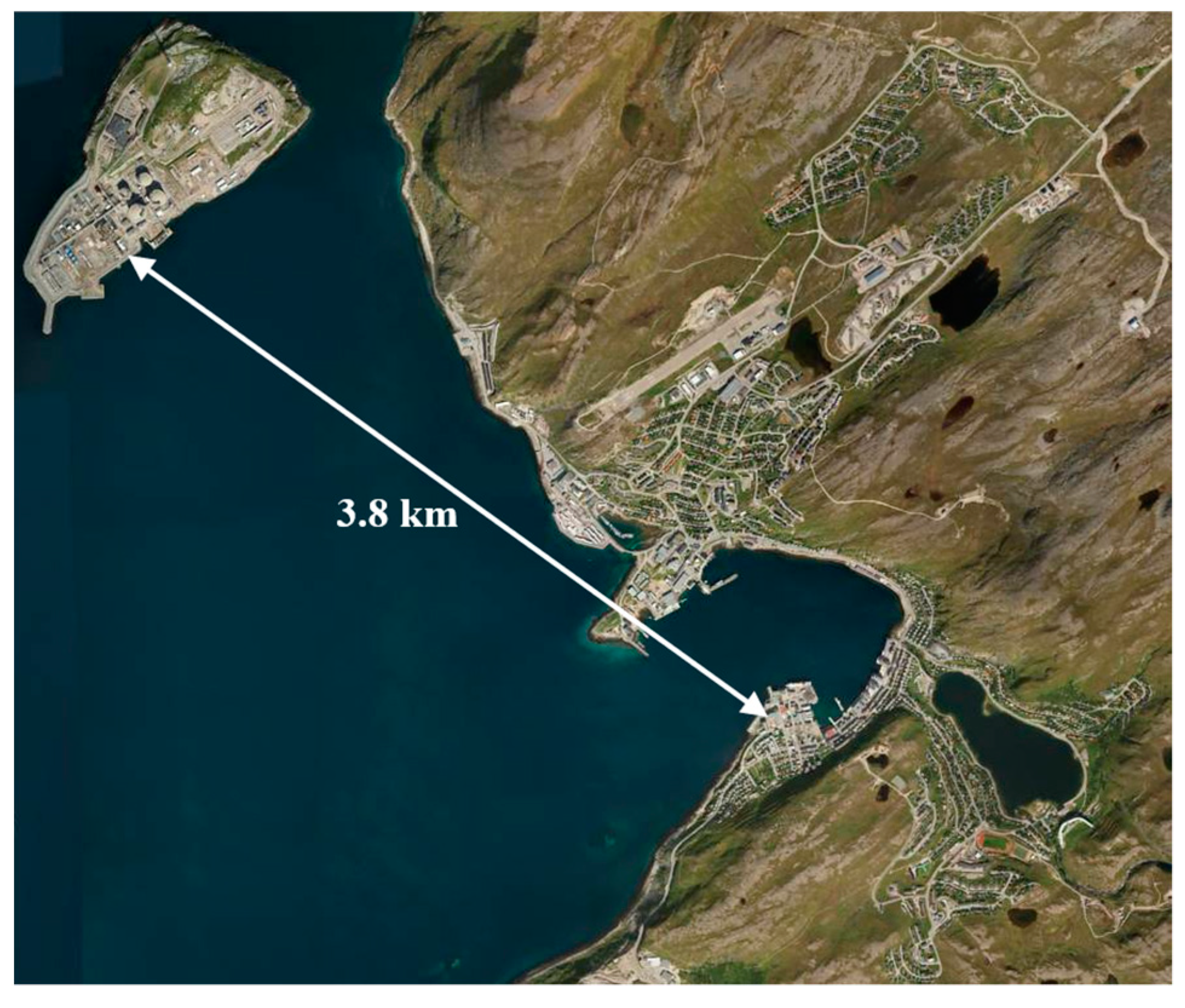
Figure 1. The LNG plant at Melkøya island, 3.8 km from the Hammerfest town center. (Aerial photo from www.norgeibilder.no, accessed on 2 February 2022).
Energies 15 07719 g001
Figure 2. A principal sketch of the unengaged air intake, with coarse filters (left) and fine filters (right), while the heat exchanger was supplied hot oil at 260 °C.
Energies 15 07719 g002
Figure 3. The air intake hot oil fire. (Photo: Bjarne Halvorsen, reproduced with permission).
Energies 15 07719 g003
Figure 4. Air intake (a) coarse bag filter (Hi-FLO XLT); (b) fine filter (Cam-GT-98 klasse F9), [7].
Energies 15 07719 g004
Figure 5. The 2 m3 test chamber for testing filter cassettes.
Energies 15 07719 g005
Figure 6. Initial Ignition Tests: (a) Flaming combustion of filter test specimen; (b) ignition test demonstrating glowing glass fibers.
Energies 15 07719 g006
Figure 7. Self-heating tests in a muffle furnace: (a) The virgin test specimens (10 cm × 10 cm stacked to 8 cm height) and ready for testing at a given holding temperature. (b) After muffle furnace self-heating test, with visible indent marks by the thermocouples embedded during heat treatment.
Energies 15 07719 g007
Figure 8. Temperatures recorded in virgin filters: (a) 1 K/minute heating rate and setpoint 200 °C; (b) 10 K/minute heating rate and setpoint 205 °C.
Energies 15 07719 g008
Figure 9. Temperatures recorded in used filters: (a) 10 K/minute heating rate and setpoint 180 °C; (b) 10 K/minute heating rate and setpoint 205 °C.
Energies 15 07719 g009
Figure 10. The time derivative of the temperature as a function of the temperature for used filters, i.e., data from Figure 9b.
Energies 15 07719 g010
Figure 11. Principle heat production (Equation (1), red line) and heat loss (Equation (2), blue lines) as a function of temperature for a small (solid blue line) and a big (dashed blue line) test specimen, respectively.
Energies 15 07719 g011
Figure 12. Temperatures recorded in used filters, 10 K/minute heating rate and setpoint 205 °C, resulting in an early runaway reaction.
Energies 15 07719 g012
Figure 13. Used filter bag cassette tested at 200 °C. Photo taken 4–5 s after a rapid transition to flaming combustion.
Energies 15 07719 g013
Figure 14. Coarse bag filter cassettes tested 170 °C: (a) Use filter cassette; (b) Virgin filter cassette.
Energies 15 07719 g014
Figure 15. Used coarse filter bag cassette tested at 150 °C.
Energies 15 07719 g015
Figure 16. Representative pterygota from a used coarse filter bag.
Energies 15 07719 g016
Figure 17. Photo of the GTG 4 air intake fire with the process depressurization flare in the background. Photo by Stein Lyder taken from Sørøysundekspressen. (Reproduced with permission.).
Energies 15 07719 g017
Publisher’s Note: MDPI stays neutral with regard to jurisdictional claims in published maps and institutional affiliations.